欧姆龙CJ系列操作手册(中文)
- 格式:pdf
- 大小:16.22 MB
- 文档页数:172

SYSMAC CS/CJ系列CS1W-AD041(-V1)/AD081 (-V1) CS1W-DA041/DA08V/DA08C CS1W-MAD44CJ1W-AD041-V1/AD081(-V1) CJ1W-DA021/DA041/DA08V CJ1W-MAD42模拟量I/O单元操作手册2003年6月修订v注意:欧姆龙产品必须由合格的操作员按照正确的程序使用,并且只能用于本手册所规定的目的。
下列标识用来表示和区分本手册中的各种注意事项。
应该对它们提示的信息予以注意,否则可能引起人员伤亡或财产损坏。
! 表示十分危急的危险情况,如不加以防止,将导致死亡或严重伤害。
! 表示潜在的危险情况,如不加以防止,可能导致死亡或严重伤害。
! 表示潜在的危险情况,如不加以防止,可能导致轻度或中度伤害,或财产损坏。
欧姆龙产品参考所有的欧姆龙产品在本手册中都有大写表示。
当“Unit ”指的是一个欧姆龙产品时,也用大写,不管它是否出现在产品全称中。
在一些展示和欧姆龙产品上出现的缩写“Ch ”经常表示的是“字”,而在文档中表示同样的意思时则用缩写“Wd ”来表示。
缩写“PLC ”表示可编程控制器。
但是在一些编程装置显示中“PC ”却用来表示可编程控制器。
可视化帮助出现在手册左列的下述标题帮助您找到不同类型的信息。
注表示有效和方便的产品操作的特殊信息。
1,2,3... 1.表示一种产品或其它,如程序、清单等的列表。
OMRON, 1999保留所有版权。
没有欧姆龙的书面同意,本出版物的任何一部分不允许被复制、收编入检索系统,或以任何形式,通过任何手段,如机械、电子、影印、录音或其它,进行传播。
本书内的信息无专利责任。
并且由于欧姆龙一直在致力于提高它的高品质产品,本手册内的信息将可能在未通知的情况下修改。
编制本手册时已经采取了各种预防措施。
欧姆龙不对错误或遗漏付负责。
并且不对由于使用本书中的信息而导致的损坏负责。
危险警告注意预防措施. . . . . . . . . . . . . . . . . . . . . . . . . . . . . . . . . . . . . . . xiii 1针对的对象. . . . . . . . . . . . . . . . . . . . . . . . . . . . . . . . . . . . . . . . . . . . . . . . . . . . . . xiv2主要预防措施. . . . . . . . . . . . . . . . . . . . . . . . . . . . . . . . . . . . . . . . . . . . . . . . . . . . xiv3安全预防措施. . . . . . . . . . . . . . . . . . . . . . . . . . . . . . . . . . . . . . . . . . . . . . . . . . . . xiv4操作环境预防措施. . . . . . . . . . . . . . . . . . . . . . . . . . . . . . . . . . . . . . . . . . . . . . . . xv5应用预防措施. . . . . . . . . . . . . . . . . . . . . . . . . . . . . . . . . . . . . . . . . . . . . . . . . . . . xvi6EC指令. . . . . . . . . . . . . . . . . . . . . . . . . . . . . . . . . . . . . . . . . . . . . . . . . . . . . . . . . xvii7其它应用指令. . . . . . . . . . . . . . . . . . . . . . . . . . . . . . . . . . . . . . . . . . . . . . . . . . . . xviii8C200H-AD003,C200H-DA003/004和C200H-MAD01预防措施 . . . . . . xviii9CS1W/CJ1W-AD041-V1/AD081-V1中的改进. . . . . . . . . . . . . . . . . . . . . . . . xix10CJ1W-DA08V和CJ1W-MAD42的修改 . . . . . . . . . . . . . . . . . . . . . . . . . . . . . xx第1章系统设计. . . . . . . . . . . . . . . . . . . . . . . . . . . . . . . . . . . . . . . 1 1-1特点和功能. . . . . . . . . . . . . . . . . . . . . . . . . . . . . . . . . . . . . . . . . . . . . . . . . . . . . . 21-2基本配置. . . . . . . . . . . . . . . . . . . . . . . . . . . . . . . . . . . . . . . . . . . . . . . . . . . . . . . . 71-3功能应用. . . . . . . . . . . . . . . . . . . . . . . . . . . . . . . . . . . . . . . . . . . . . . . . . . . . . . . . 12第2章CS系列模拟量输入单元 . . . . . . . . . . . . . . . . . . . . . . . . . 13 2-1规格. . . . . . . . . . . . . . . . . . . . . . . . . . . . . . . . . . . . . . . . . . . . . . . . . . . . . . . . . . . . 142-2操作步骤. . . . . . . . . . . . . . . . . . . . . . . . . . . . . . . . . . . . . . . . . . . . . . . . . . . . . . . . 192-3元件和开关设置. . . . . . . . . . . . . . . . . . . . . . . . . . . . . . . . . . . . . . . . . . . . . . . . . . 262-4配线. . . . . . . . . . . . . . . . . . . . . . . . . . . . . . . . . . . . . . . . . . . . . . . . . . . . . . . . . . . . 302-5与CPU单元交换数据. . . . . . . . . . . . . . . . . . . . . . . . . . . . . . . . . . . . . . . . . . . . . 342-6模拟量输入功能和操作步骤. . . . . . . . . . . . . . . . . . . . . . . . . . . . . . . . . . . . . . . . 412-7调整偏移和增益. . . . . . . . . . . . . . . . . . . . . . . . . . . . . . . . . . . . . . . . . . . . . . . . . . 492-8处理错误和警报. . . . . . . . . . . . . . . . . . . . . . . . . . . . . . . . . . . . . . . . . . . . . . . . . . 57第3章CJ系列模拟量输入单元. . . . . . . . . . . . . . . . . . . . . . . . . . 63 3-1规格. . . . . . . . . . . . . . . . . . . . . . . . . . . . . . . . . . . . . . . . . . . . . . . . . . . . . . . . . . . . 643-2操作步骤. . . . . . . . . . . . . . . . . . . . . . . . . . . . . . . . . . . . . . . . . . . . . . . . . . . . . . . . 693-3元件和开关设置. . . . . . . . . . . . . . . . . . . . . . . . . . . . . . . . . . . . . . . . . . . . . . . . . . 753-4配线. . . . . . . . . . . . . . . . . . . . . . . . . . . . . . . . . . . . . . . . . . . . . . . . . . . . . . . . . . . . 793-5与CPU单元交换数据. . . . . . . . . . . . . . . . . . . . . . . . . . . . . . . . . . . . . . . . . . . . . 833-6模拟量输入功能和操作步骤. . . . . . . . . . . . . . . . . . . . . . . . . . . . . . . . . . . . . . . . 903-7调整偏移和增益. . . . . . . . . . . . . . . . . . . . . . . . . . . . . . . . . . . . . . . . . . . . . . . . . . 983-8处理错误和警报. . . . . . . . . . . . . . . . . . . . . . . . . . . . . . . . . . . . . . . . . . . . . . . . . . 106viiCS系列模拟量输出单元 . . . . . . . . . . . . . . . . . . . . . . . . . 111 4-1规格. . . . . . . . . . . . . . . . . . . . . . . . . . . . . . . . . . . . . . . . . . . . . . . . . . . . . . . . . . . . 112 4-2操作步骤. . . . . . . . . . . . . . . . . . . . . . . . . . . . . . . . . . . . . . . . . . . . . . . . . . . . . . . . 116 4-3元件和开关设置. . . . . . . . . . . . . . . . . . . . . . . . . . . . . . . . . . . . . . . . . . . . . . . . . . 122 4-4配线. . . . . . . . . . . . . . . . . . . . . . . . . . . . . . . . . . . . . . . . . . . . . . . . . . . . . . . . . . . . 125 4-5与CPU单元交换数据. . . . . . . . . . . . . . . . . . . . . . . . . . . . . . . . . . . . . . . . . . . . . 128 4-6模拟量输出功能和操作步骤. . . . . . . . . . . . . . . . . . . . . . . . . . . . . . . . . . . . . . . . 135 4-7调整偏移和增益. . . . . . . . . . . . . . . . . . . . . . . . . . . . . . . . . . . . . . . . . . . . . . . . . . 139 4-8处理错误和警报 . . . . . . . . . . . . . . . . . . . . . . . . . . . . . . . . . . . . . . . . . . . . . . . . . 149第5章CJ系列模拟量输出单元. . . . . . . . . . . . . . . . . . . . . . . . . . 155 5-1规格. . . . . . . . . . . . . . . . . . . . . . . . . . . . . . . . . . . . . . . . . . . . . . . . . . . . . . . . . . . . 156 5-2操作步骤. . . . . . . . . . . . . . . . . . . . . . . . . . . . . . . . . . . . . . . . . . . . . . . . . . . . . . . . 160 5-3元件和开关设置. . . . . . . . . . . . . . . . . . . . . . . . . . . . . . . . . . . . . . . . . . . . . . . . . . 167 5-4配线. . . . . . . . . . . . . . . . . . . . . . . . . . . . . . . . . . . . . . . . . . . . . . . . . . . . . . . . . . . . 169 5-5与CPU单元交换数据. . . . . . . . . . . . . . . . . . . . . . . . . . . . . . . . . . . . . . . . . . . . . 173 5-6模拟量输出功能和操作步骤. . . . . . . . . . . . . . . . . . . . . . . . . . . . . . . . . . . . . . . . 181 5-7调整偏移和增益. . . . . . . . . . . . . . . . . . . . . . . . . . . . . . . . . . . . . . . . . . . . . . . . . . 188 5-8处理错误和警报 . . . . . . . . . . . . . . . . . . . . . . . . . . . . . . . . . . . . . . . . . . . . . . . . . 199第6章CS系列模拟量I/O单元. . . . . . . . . . . . . . . . . . . . . . . . . . 205 6-1规格. . . . . . . . . . . . . . . . . . . . . . . . . . . . . . . . . . . . . . . . . . . . . . . . . . . . . . . . . . . . 206 6-2操作步骤. . . . . . . . . . . . . . . . . . . . . . . . . . . . . . . . . . . . . . . . . . . . . . . . . . . . . . . . 214 6-3元件和开关设置. . . . . . . . . . . . . . . . . . . . . . . . . . . . . . . . . . . . . . . . . . . . . . . . . . 221 6-4配线. . . . . . . . . . . . . . . . . . . . . . . . . . . . . . . . . . . . . . . . . . . . . . . . . . . . . . . . . . . . 224 6-5与CPU单元交换数据. . . . . . . . . . . . . . . . . . . . . . . . . . . . . . . . . . . . . . . . . . . . . 228 6-6模拟量输入功能和操作步骤. . . . . . . . . . . . . . . . . . . . . . . . . . . . . . . . . . . . . . . . 236 6-7模拟量输出功能和操作步骤. . . . . . . . . . . . . . . . . . . . . . . . . . . . . . . . . . . . . . . . 243 6-8比率转换功能. . . . . . . . . . . . . . . . . . . . . . . . . . . . . . . . . . . . . . . . . . . . . . . . . . . . 246 6-9调整偏移和增益. . . . . . . . . . . . . . . . . . . . . . . . . . . . . . . . . . . . . . . . . . . . . . . . . . 249 6-10处理错误和警报. . . . . . . . . . . . . . . . . . . . . . . . . . . . . . . . . . . . . . . . . . . . . . . . . . 265viiiCJ系列模拟量I/O单元 . . . . . . . . . . . . . . . . . . . . . . . . . . 271 7-1规格. . . . . . . . . . . . . . . . . . . . . . . . . . . . . . . . . . . . . . . . . . . . . . . . . . . . . . . . . . . . 2727-2操作步骤. . . . . . . . . . . . . . . . . . . . . . . . . . . . . . . . . . . . . . . . . . . . . . . . . . . . . . . . 2797-3元件和开关设置. . . . . . . . . . . . . . . . . . . . . . . . . . . . . . . . . . . . . . . . . . . . . . . . . . 2867-4配线. . . . . . . . . . . . . . . . . . . . . . . . . . . . . . . . . . . . . . . . . . . . . . . . . . . . . . . . . . . . 2897-5与CPU单元交换数据. . . . . . . . . . . . . . . . . . . . . . . . . . . . . . . . . . . . . . . . . . . . . 2937-6模拟量输入功能和操作步骤. . . . . . . . . . . . . . . . . . . . . . . . . . . . . . . . . . . . . . . . 3027-7模拟量输出功能和操作步骤. . . . . . . . . . . . . . . . . . . . . . . . . . . . . . . . . . . . . . . . 3117-8比率转换功能. . . . . . . . . . . . . . . . . . . . . . . . . . . . . . . . . . . . . . . . . . . . . . . . . . . . 3177-9调整偏移和增益. . . . . . . . . . . . . . . . . . . . . . . . . . . . . . . . . . . . . . . . . . . . . . . . . . 3207-10处理错误和警报. . . . . . . . . . . . . . . . . . . . . . . . . . . . . . . . . . . . . . . . . . . . . . . . . . 336附录A尺寸 . . . . . . . . . . . . . . . . . . . . . . . . . . . . . . . . . . . . . . . . . . . . . . . . . . . . . . . . . . . 343B程序样本 . . . . . . . . . . . . . . . . . . . . . . . . . . . . . . . . . . . . . . . . . . . . . . . . . . . . . . . 345C数据存储器代码表 . . . . . . . . . . . . . . . . . . . . . . . . . . . . . . . . . . . . . . . . . . . . . . . 355ixxi关于本手册:这本手册描述了CS1W-AD041,4CS1W-AD081,CS1WAD041-V1,CS1W-AD081-V1,CJ1W-AD041-V1,CJ1W-AD081和CJ1W-AD081-V1 模拟量输入单元; CS1W-DA041,CS1W-DA08V ,CS1W-DA08C ,CJ1W-DA021,CJ1W-DA041和CJ1WDA08V 模拟量输出单元;以及CS1W-MAD44和CJ1W-MAD42 模拟量I/O 单元的安装和操作。


CJ系列内置I/OCJ1M CPU22/CPU23 CPU单元操作手册2002年11月ivv注意:OMRON 产品是为合格的操作人员按照正常步骤使用并只为本手册中所叙述的目的而制造的。
下列约定是用来指出本手册中的注意事项,并对其进行分类。
始终注意它们所规定的情况。
不注意这些注意事项能导致对人体的伤害或危及财产。
! 指出一个急迫的危险情况,如不避免之,它会导致死亡或严重伤害。
! 指出一个潜在的危险情况,如不避免之,它能导致死亡或严重伤害。
! 指出一个潜在的危险情况,如不避免之,它可能导致轻度的或中度的伤害,或财产损失。
OMRON 产品附注所有OMRON 产品在本手册中都以大写字母表示。
当字“单元”表示 OMRON 产品时,它也以大写字母表示,不管它是否以产品的正式名称出现。
缩写“Ch ”,它出现在某些显示中和某些OMRON 产品上,往往表示“字”,在这个意义上在文件中缩写为“Wd ”。
缩写“PLC ”表示可编程序控制器。
但是,在有些编程设备的显示中用“ PC ”来表示可编程序控制器。
直观标题列在本手册左侧的下列标题是帮助读者确定各种不同类形的资料。
注指出对有效而方便地运用产品特别重要的资料。
1,2,3...1.指出一种或另一种的列举说明,如步骤,检查表,等。
OMRON, 2002版权所有,事先未经OMRON 公司书面许可,本出版物的任何部分都不可用任何形式,或用任何方法,机械的,电子的,照相的,录制的或其它方式进行复制,存入检索系统或传送。
对使用这里所包含的资料不负专利责任。
然而,因为OMRON 公司不断努力改进其高质量的产品,所以本手册中所含有的资料可随时改变而不另行通知。
在编写本手册时注意了一切可能的注意事项,然而,OMRON 公司对于可能的错误或遗漏不承担责任。
对于使用本出版物中所包含的资料导致的损害也不承担任何责任。
危险警告注意vi注意事项 . . . . . . . . . . . . . . . . . . . . . . . . . . . . . . . . . . . . .xi 1面向的读者 . . . . . . . . . . . . . . . . . . . . . . . . . . . . . . . . . . . . . . . . . . . . . . . . . . . . . . . xii2一般注意事项 . . . . . . . . . . . . . . . . . . . . . . . . . . . . . . . . . . . . . . . . . . . . . . . . . . . . . xii3安全注意事项 . . . . . . . . . . . . . . . . . . . . . . . . . . . . . . . . . . . . . . . . . . . . . . . . . . . . . xii4操作环境注意事项. . . . . . . . . . . . . . . . . . . . . . . . . . . . . . . . . . . . . . . . . . . . . . . . . . xiv5应用注意事项 . . . . . . . . . . . . . . . . . . . . . . . . . . . . . . . . . . . . . . . . . . . . . . . . . . . . . xiv6与EC规程的一致性 . . . . . . . . . . . . . . . . . . . . . . . . . . . . . . . . . . . . . . . . . . . . . . . . xviii第1章性能. . . . . . . . . . . . . . . . . . . . . . . . . . . . . . . . . . . . . . . . .1 1-1性能 . . . . . . . . . . . . . . . . . . . . . . . . . . . . . . . . . . . . . . . . . . . . . . . . . . . . . . . . . . . . 21-2按用途划分的功能. . . . . . . . . . . . . . . . . . . . . . . . . . . . . . . . . . . . . . . . . . . . . . . . . . 5第2章概述. . . . . . . . . . . . . . . . . . . . . . . . . . . . . . . . . . . . . . . . .11 2-1内置CPU单元输入的分配 . . . . . . . . . . . . . . . . . . . . . . . . . . . . . . . . . . . . . . . . . . . 122-2内置CPU单元输出的分配 . . . . . . . . . . . . . . . . . . . . . . . . . . . . . . . . . . . . . . . . . . . 152-3原点搜索功能的分配. . . . . . . . . . . . . . . . . . . . . . . . . . . . . . . . . . . . . . . . . . . . . . . . 16第3章I/O规格和配线. . . . . . . . . . . . . . . . . . . . . . . . . . . . . . . . .19 3-1I/O 规格. . . . . . . . . . . . . . . . . . . . . . . . . . . . . . . . . . . . . . . . . . . . . . . . . . . . . . . . . . 203-2配线 . . . . . . . . . . . . . . . . . . . . . . . . . . . . . . . . . . . . . . . . . . . . . . . . . . . . . . . . . . . . 233-3配线示例. . . . . . . . . . . . . . . . . . . . . . . . . . . . . . . . . . . . . . . . . . . . . . . . . . . . . . . . . 32第4章数据区分配和PLC设置设定 . . . . . . . . . . . . . . . . . . . . . .51 4-1内置I/O的数据区分配 . . . . . . . . . . . . . . . . . . . . . . . . . . . . . . . . . . . . . . . . . . . . . . 524-2PLC设置设定. . . . . . . . . . . . . . . . . . . . . . . . . . . . . . . . . . . . . . . . . . . . . . . . . . . . . 524-3辅助区数据分配 . . . . . . . . . . . . . . . . . . . . . . . . . . . . . . . . . . . . . . . . . . . . . . . . . . . 654-4脉冲输出时标志操作. . . . . . . . . . . . . . . . . . . . . . . . . . . . . . . . . . . . . . . . . . . . . . . . 72第5章内置I/O功能使用说明. . . . . . . . . . . . . . . . . . . . . . . . . . .73 5-1内置输入. . . . . . . . . . . . . . . . . . . . . . . . . . . . . . . . . . . . . . . . . . . . . . . . . . . . . . . . . 745-2内置输出. . . . . . . . . . . . . . . . . . . . . . . . . . . . . . . . . . . . . . . . . . . . . . . . . . . . . . . . . 915-3原点搜索和原点返回功能 . . . . . . . . . . . . . . . . . . . . . . . . . . . . . . . . . . . . . . . . . . . . 113第6章编程举例 . . . . . . . . . . . . . . . . . . . . . . . . . . . . . . . . . . . . .135 6-1内置输出. . . . . . . . . . . . . . . . . . . . . . . . . . . . . . . . . . . . . . . . . . . . . . . . . . . . . . . . . 136vii附录A脉冲控制指令的组合 . . . . . . . . . . . . . . . . . . . . . . . . . . . . . . . . . . . . . . . . . . . . . . . 145 B脉冲指令在其它CPU单元中的应用. . . . . . . . . . . . . . . . . . . . . . . . . . . . . . . . . . . . 149 C中断响应时间 . . . . . . . . . . . . . . . . . . . . . . . . . . . . . . . . . . . . . . . . . . . . . . . . . . . . . 153viii关于本手册:本手册介绍CJ1M CPU22和CJ1M CPU23 CPU单元支持的内置I/O的安装和操作,还含有下面介绍的章节。
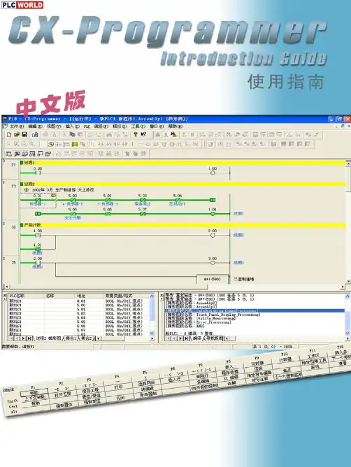
CX-One/CX-Programmer有PDF文件格式的操作手册。
使用CX-Programmer之前请先阅读操作手册中的“注”和“注意事项”。
CX-Programmer免费版的显示界面,有一部分可能与本指南的所示界面有所不同,敬请注意。
“CX-Programmer使用指南”描述了CX-Programmer的基本操作步骤。
详细描述请参阅PDF文件中的帮助或操作手册。
*要显示PDF文件,您的PC中需要4.0或以上版本的Acrobat Reader。
•••••••••••••••••••••••••••••••••••••••••••••••••••••••••••••1-1•••••••••••••••••••••••••••••••••••••••••••••••••1-1•••••••••••••••••••••••••••••••••••••••••••••••••••••••1-5••••••••••••••••••••••••••••••••••••••••••••••••1-7••••••••••••••••••••••••••••••••••••••••••••••••1-8••••••••••••••••••••••••••••••••••••••••••••••••••••••••••••••1-9••••••••••••••••••••••••••••••••••••••••••••1-10•••••••••••••••••••••••••••••••••••••••••••••••••••••••••••••1-11••••••••••••••••••••••••••••••••••••••••••••••••1-13•••••••••••••••••••••••••••••••••••••••••••••••••••••••••1-14••••••••••••••••••••••••••••••••••••••••••••••••••••1-15••••••••••••••••••••••••••••••••••••••••••••••••••••••1-16•••••••••••••••••••••••••••••••••••••••••••••••••••1-18••••••••••••••••••••••••••••••••••••••••••••••••••••1-19•••••••••••••••••••••••••••••••••••••••••••••••••••1-19••••••••••••••••••••••••••••••••••••••••••••••••1-20••••••••••••••••••••••••••••••••••••••••••••••1-21••••••••••••••••••••••••••••••••••••••••••••••1-21••••••••••••••••••••••••••••••••••••••••••••••••••••1-22•••••••••••••••••••••••••••••••••••••••••••••••••••1-22•••••••••••••••••••••••••••••••••••••••1-23•••••••••••••••••••••••••••••••••••••••••1-24••••••••••••••••••••••••••••••••••••1-25•••••••••••••••••••••••••••••••••••1-26 ••••••••••••••••••••••••••••••••••••••••••••••••••1-27•••••••••••••••••••••••••••••••••••••1-28••••••••••••••••••••••••••••••••••••••••••••••••1-29••••••••••••••••••••••••••••••••••••••••••••••••1-30••••••••••••••••••••••••••••••••••••••••••••••1-31 •••••••••••••••••••••••••••••••••••••••••••••1-31目录第二章在线/调试适用PC 适用设备型号第一章安装和启动1. 安装1-1. 安装CX-Programmer 1-2. 在线注册2.打开新工程和设置设备型号3.打开新工程和设置设备型号4. 主窗口4-1.兼容SYSWIN 软件的按键分配4-2. 段4-3.删除和显示其他窗口5.创建程序5-1.常开接点的输入5-2.线圈的输入5-3.符号注释的编辑5-4.条注释的输入5-5.常闭接点的输入5-6.元素注释的输入5-7.上升沿微分接点的输入5-8.下降沿微分接点的输入5-9.向上垂线的输入5-10.向下垂线的输入5-11.高级指令的输入1 -字符串的输入5-12.高级指令的输入1 -有用的功能5-13.辅助继电器的输入-1.0 秒时钟脉冲位5-14.高级指令的输入2 –微分指令的输入5-15.或逻辑的条输入5-16.高级指令的输入3–通过功能号来输入5-17.定时器指令的输入5-18.计数器指令的输入5-19.条的编辑…复制和粘贴5-20. END 指令的输入1. 程序错误检查(编译)2.进入在线3.监视4.监视-2同时监视程序中多处位置5.监视-3以十六进制数监视6.监视-4查看窗口7.监视-5查看窗口的当前值修改和二进制数监视8.查看窗口的有用功能9.监视-6监视窗口-210.监视-7以短条形式显示11.监视-8微分监视12.强制为On/Off 13.强制-on/off 位的显示列表14.修改定时器的设定值15.修改定时器的当前值16.查找功能-1通过地址引用工具查找17.查找功能-2梯形图的折回查找18.查找功能-3通过注释的关键字来查找19.查找功能-4进入条注释20.查找功能-5查找位地址21.在线编辑实用的功能•••••••••••••••••••••••••••••••••••••••••••••••••••2-1•••••••••••••••••••••••••••••••••••••••••••••••••••••••••2-2•••••••••••••••••••••••••••••••••••••••••••••••••••••••••••2-3••••••••••••••••••••••••••••••••••••••••2-4•••••••••••••••••••••••••••••••••••••••••••2-4•••••••••••••••••••••••••••••••••••••••••••••••••2-5•••••••••••••••••••••••••••••••••2-6•••••••••••••••••••••••••••••••••••••••••••••••••2-7•••••••••••••••••••••••••••••••••••••••••••••••••2-8•••••••••••••••••••••••••••••••••••••••••••••2-9••••••••••••••••••••••••••••••••••••••••••••••••2-10••••••••••••••••••••••••••••••••••••••••••••••••••••••2-11••••••••••••••••••••••••••••••••••••••••••••••2-11•••••••••••••••••••••••••••••••••••••••••••••••••2-12•••••••••••••••••••••••••••••••••••••••••••••••••2-12•••••••••••••••••••••••••••••••••••••••2-13•••••••••••••••••••••••••••••••••••••••2-14•••••••••••••••••••••••••••••••••••••2-16••••••••••••••••••••••••••••••••••••••••••••2-17••••••••••••••••••••••••••••••••••••••••••••••2-18•••••••••••••••••••••••••••••••••••••••••••••••••••••••••2-19••••••••••••••••••••••••••••••••••••••••••••••••••••••Appendix适用PC硬件要求*1:对于Windows95和CS/CJ 系列PLC, 不能使用CX-Programmer 的I/O 表和单元设置(参数设置、专用工具激活、消耗电流指示、底板宽度指示和高功能单元DIP 开关状态监视等)。

欧姆龙PLC样本与手册全集小型机CP1H选型样本(中文)R05-CN-03CP1H/CP1L选型样本(中文)SBCA-C-051DCP1L选型样本(英文)P20E-EN-01CP1E中英文选型样本CP1H操作手册(中文)W450-CN5-02CP1H操作手册(英文)W450-E1-01CP1L操作手册(中文)W462-CN5-03CP1L操作手册(英文)W462-E1-06CP1E单元软件用户手册(中英文)W480-E1-01W480-CN5-01 CP1E单元硬件用户手册(中英文)W479-E1-01W479-CN5-01 CP1E单元硬件用户手册(英文)(包含NA)W479-E1-03 CP1H/CP1L编程手册(英文)W451-E1-03CP1H/CP1L编程手册(中文)CP1E指令参考手册(中文)W483-CN5-04CP1E指令手册(英文)CPM1A-V1选型样本(英文)P039E1-11CPM1A操作手册(英文)W317-E1-4CPM1/1A/2A/2C/SRM1编程手册(英文)W353-E1-1CPM1A操作手册(中文)OMP-ZCO97101BCPM1A/2A/2AH/2C编程手册(中文)CPM1操作手册(英文)W262-E1-4CPM2A/2C选型样本(英文)P049-E1-08CPM2AH选型样本(中文)CPM2AH-S选型样本(中文).P01Z-CN-01CPM2A操作手册(英文)W352-E1-1CPM2AH-S操作手册(中文)CPM2A/CPM2AH操作手册(中文)CPM2C选型样本(英文)CPM2C操作手册(英文)W356-E1-08CPM2B操作手册(中文)OMP-AD000102ACPM2B-S001M-DRT操作手册(英文)W399-E1-1中型机CJ1系列选型样本(中文)CJ2H/CJ2M选型样本(中文)SBCE-CN-058DC200HX/C200HG/C200HE选型样本(中文)CJ1M内置I/O操作手册(中文)W395-C1-01 CJ1操作手册(中文)W393-C1-02CJ1编程手册(中文)W340-C1-08CJ1最新编程手册(英文)W340-E1-1CJ2CPU单元硬件操作手册(中文)W472-CN5-06 CJ2操作手册(英文)W472-E1-01CJ2M-MD操作手册(英文)W486-E1-01CJ2编程手册(英文)W473-E1-01CJ1W-AD/DA操作手册(中文)W345-C1-05CJ1W-TC操作手册(中文)W396CJ1W-PTS操作手册(英文)W368-E1-07C200HX/HG/HE编程手册(中文)OEZ-ZCP97201AC200HE/HG/HX操作手册(中文)OEZ-ZCI96201AC200H模拟量(AD001/DA001)操作手册(中文)OMP-ZCO99406A C200H模拟量I(AD003/DA003)操作手册(英文)W325-E1-04 C200H-TC温度控制单元操作手册(英文)W124-E1-5C200H操作手册(英文)W130-E3-5C200HS安装手册(英文)C200HS操作手册(英文)CQM1H选型样本(中文)CQM1H操作手册(中文)CQM1H编程手册(中文)CQM1H系列CPU和内装板操作手册(英文)CQM1H系列CPU和内装板编程手册(英文)CQM1H特殊I/O单元操作手册(中文)CQM1H/CQM1特殊I/O手册(英文)大型机CS1W-PTS过程控制I/O模块操作手册(英文)W368-E1-07CS1-H选型样本(中文)CS1D选型样本(中文)CS1可编程控制器操作手册(中文)W339-CN5-10CS1编程手册(中文)W340-C1-08CS1最新编程手册(英文)CS1D双机操作手册(英文)W405-E1-06CS1W-AD/DA操作手册(中文)W345-C1-05CS1W-AD/DA最新操作手册(英文)W345-E1-11C500安装手册(英文)W132-E1-3DC500编程手册(英文)W131-E1-02C500-LK操作手册(英文)W143-E1-05串口通讯C200HW-COM01/02/03/04/05/06通讯板操作手册(英文)-W304-E1-05通讯命令参考手册(英文)W342-E1-15CS1/CJ1W-SCU/SCB串行通讯单元/板卡操作手册(英文)-W336-E1-10 CQM1H-SCB41操作手册(英文)-W365-E1-02NT-AL001使用手册(英文)C200HPC-Link系统手册(英文)-W135-E1-2B以太网CS1-ETN01/11和CJ1-ETN11操作手册(英文)-W343-E1-07CS1/CJ1-ETN21操作手册(英文)-W420-E1-06CS1/CJ1-ETN21应用手册(英文)-W421-E1-04CS1D-ETN21D操作手册(英文)-W430-E1-02CJ1M-CPU1□-ETN操作手册(英文)-W441-E1-03ControllerLink3G8F7-CLK21/52/12安装指南(英文)W388-E1-2C200HW/CVM1-CLK21操作手册(中文)-OEZ-ZCO97404ACS/CJ1W/C200HW/CVM1/CQM1H-CLK21CS1W-RPT01/02/03操作手册(英文)-W309-E1-113G8F7-CLK12/21/52(-EV1)/13/23/53(-E)操作手册(英文)-W383-E1-04CS1W/CVM1-CLK12/52/13/53操作手册(英文)-W370-E1-07DeviceNet(Compobus/D)CS1/CJ1-DRM21-V1操作手册(英文)-W380-E1-07CVM1/C200HW-DRM21/CQM1-DRT21DRT1系列操作手册(英文)-W267-E1-6 CS1/CJ1系列DRM21操作手册(中文繁体)-SBCD-314H-TW5-01ITNC-EPX01/ITNC-EPX01-DRM开放网络控制器操作手册(英文)-V228-E1-02 C200HW/CQM1-DRT21/DRT1系列操作手册(英文)-W347-E1-06DeviceNet操作手册(英文)-W267-E1-113G3MV-PDRT1-SINVDeviceNet通讯单元操作手册(英文)-I529-E1-02DRT2系列从单元操作手册(英文)-W404-E1-08NT-DRT21DeviceNet接口单元操作手册(英文)-V066-E1-1DRT-COM/GT1系列DeviceNetMultipleI/O操作手册(英文)-W438-E1-05 CPM2C-S/CPM2C-S100C/S110C/S100C-DRT操作手册(英文)-W337-E1-13G3FV-PDRT1-SIN操作手册(英文)-I525-E1-023G3MV/3G3RV-PDRT2Devicenet操作手册(英文)-I539-E1-03GRT1-DRT模块操作手册(英文)-W455-E1-06OMNUCW系列伺服驱动器R88A-NCW152-DRT操作手册(英文)-I538-E1-01 OMNUCW系列伺服驱动器R88A-NCW152-DRT选型样本(英文)-DS13P1 CS/CJ1W-DRM21安装AB公司DRT丛站使用说明(英文)Compobus/SC200HW/CJ1/CQM1-SRM21SRT1/SRT2操作手册(英文)-W226-E1-09 CompoNetCS/CJ1W-CRM21操作手册(英文)-W456-E1-03CompoNet从站模块和中继模块操作手册(英文)W457-E1-03 Profibus-DPC200HW-PRM21PROFIBUS-DP主单元操作手册(英文)-W349-E1-1N CS1W/CJ1W-PRM21Profibus主单元操作手册(英文)-W409-E2-03C200HW-PRT21操作手册(英文)-W901-E2-1CJ1W-PRT21操作手册(英文)-W408-E2-02PRT1-COM/GT1操作手册(英文)-W900-E2-02CQM1H-PRT21操作手册(英文)。

CJ SeriesEtherNet/IP™ Connection GuideOMRON CorporationZW-series Displacement SensorP536-E1-01About Intellectual Property Right and TrademarksMicrosoft product screen shots reprinted with permission from Microsoft Corporation.Windows is a registered trademark of Microsoft Corporation in the USA and other countries. ODVA and EtherNet/IP™ are trademarks of ODVA.Ethernet is a registered trademark of the Xerox Corporation.Company names and product names in this document are the trademarks or registered trademarks of their respective companies.Table of Contents1.Related Manuals (1)2.Terms and Definitions (2)3.Remarks (3)4.Overview (5)5.Applicable Devices and Support Software (6)5.1.Applicable Devices (6)5.2.Device Configuration (7)6.EtherNet/IP Connection Procedure (9)6.1.EtherNet/IP Communications Settings (9)6.2.Work Flow (12)6.3.Setting Up the Displacement Sensor (13)6.4.Setting Up the PLC (21)6.5.Checking the EtherNet/IP Communications (44)7.Initialization Method (49)7.1.Initializing the PLC (49)7.2.Initializing the Displacement Sensor (50)8.Revision History (51)1. Related Manuals1. Related ManualsThe table below lists the manuals related to this document.To ensure system safety, make sure to always read and heed the information provided in all Safety Precautions, Precautions for Safe Use, and Precaution for Correct Use of manuals for each device which is used in the system.Cat. No. Model Manual nameCJ-series CJ2 CPU Unit Hardware User's Manual W472 CJ2H-CPU6[]-EIPCJ2H-CPU6[]CJ2M-CPU[][]CJ-series CJ2 CPU Unit Software User's Manual W473 CJ2H-CPU6[]-EIPCJ2H-CPU6[]CJ2M-CPU[][]EtherNet/IP™ Unit Operation Manual W465 CJ1W-EIP21CJ2H-CPU6[]-EIPCJ2M-CPU3[]W446 - CX-Programmer Operation ManualZ332 ZW-CE1[] ZW Series Displacement Sensor (Confocal Fiber Type)User's Manual2. Terms and Definitions2. Terms and DefinitionsTerm Explanation and DefinitionTag data link A function that enables cyclic tag data exchanges on an EtherNet/IPnetwork between PLCs or between PLCs and with other devices withoutusing a user program in the PLCs.Tag A tag is a unit that is used to exchange data with tag data links. Data isexchanged between the local network variables and remote networkvariables specified in the tags or between specified I/O memory areas.Tag set When a connection is established, from 1 to 8 tags (including Controllerstatus) is configured as a tag set. Each tag set represents the data thatis linked for a tag data link connection.Connection A connection is used to exchange data as a unit within which datasynchronicity is maintained.Thus, data synchronicity is maintained for all the data exchanged for thetags in one data set.Originator and Target To perform tag data links, one node requests the opening of acommunications line called "connection" to perform tag data links.The node that requests opening the connection is called "originator",and the node that receives the request is called "target".Node With EtherNet/IP network, 1 node is 1 EtherNet/IP port.Tag data link parameter The tag data link parameter is the setting data to perform the tag data link. It includes the data to set tags, tag sets, and connections.EDS file A file that contains the I/O points of EtherNet/IP devices and the parameters that can be set via EtherNet/IP.3. Remarks(1) Understand the specifications of devices which are used in the system. Allow somemargin for ratings and performance. Provide safety measures, such as installing safetycircuit in order to ensure safety and minimize risks of abnormal occurrence.(2) To ensure system safety, always read and heed the information provided in all SafetyPrecautions, Precautions for Safe Use, and Precaution for Correct Use of manuals foreach device used in the system.(3) The users are encouraged to confirm the standards and regulations that the system mustconform to.(4) It is prohibited to copy, to reproduce, and to distribute a part of or whole part of thisdocument without the permission of OMRON Corporation.(5) This document provides the latest information as of April 2013. The information on thismanual is subject to change without notice for improvement.The following notation is used in this document.Precautions for Safe UsePrecautions on what to do and what not to do to ensure safe usage of the product.Precautions for Correct UsePrecautions on what to do and what not to do to ensure proper operation and performance.Additional InformationAdditional information to read as required.This information is provided to increase understanding or make operation easier.4. Overview4. OverviewThis document describes the procedure to connect the Displacement Sensor (ZW series) of OMRON Corporation (hereinafter referred to as OMRON) with CJ-series ProgrammableController + Ethernet/IP Unit (hereinafter referred to as the PLC ), and the procedure to check their connection.Refer to Section 6. Connection Procedure to understand the setting method and key points to connect the devices via EtherNet I/P.In this document, CJ-series EtherNet/IP Unit and the built-in EtherNet/IP port of CJ-series CJ2 CPU Unit are collectively called as the "EtherNet/IP Unit".5. Applicable Devices and Support Software5.1. Applicable DevicesThe applicable devices are as follows:Manufacturer Name ModelOMRON CJ2 CPU Unit CJ2[]-CPU[][]OMRON EtherNet/IPUnit CJ1W-EIP21CJ2H-CPU6[]-EIPCJ2M-CPU3[]OMRON ConfocalFiberTypeDisplacement Sensor Controller ZW-CE1[] ZW-CE1[]TOMRON SensorHead ZW-S[][]Additional InformationAs applicable devices above, the devices with the models and versions listed in Section 5.2.are actually used in this document to describe the procedure for connecting devices and checking the connection.You cannot use devices with versions lower than the versions listed in Section 5.2.To use the above devices with versions not listed in Section 5.2 or versions higher than those listed in Section 5.2, check the differences in the specifications by referring to the manuals before operating the devices.Additional InformationThis document describes the procedure to establish the network connection. Except for the connection procedure, it does not provide information on operation, installation or wiring method. It also does not describe the functionality or operation of the devices. Refer to the manuals or contact your OMRON representative.5.2. Device ConfigurationThe hardware components to reproduce the connection procedure of this document are as follows:CJ2M-CPU32(Built-in EtherNet/IP port)Personal computer(CX-One installed)ZW-S40Calibration ROMPrecautions for Correct UseUpdate the CX-Programmer and Network Configurator to the versions specified in this section or higher versions using the auto update function.If a version not specified in this section is used, the procedures described in Section 6 and subsequent sections may not be applicable. In that case, use the equivalent procedures described in the CX-Programmer Operation Manual (Cat. No. W446) and Network Configurator Online Help.5. Applicable Devices and Support SoftwareAdditional InformationThe system configuration in this document uses USB for the connection between the personal computer and PLC. When installing the USB driver, please refer to A-5 Installing the USB Driver in the CJ-series CJ2 CPU Unit Hardware User's Manual (Cat. No. W472).6. EtherNet/IP Connection ProcedureThis section explains the procedure for connecting the Displacement Sensor to the PLC via EtherNet/IP.6.1. EtherNet/IP Communications SettingsThe settings shown in the table below are used to explain the procedure for connecting the PLC.This document explains the procedure for setting up the PLC and Displacement Sensor from the factory default setting. For the initialization, refer to Section 7 Initialization Method.6.1.1. SettingsThe settings of the PLC (EtherNet/IP Unit) and the Displacement Sensor are as follows:PLC (EtherNet/IP Unit)(node 1) Displacement Sensor(node 2)Unit number 0 -Node address 1 2IP address 192.168.250.1 192.168.250.2Subnet mask 255.255.255.0 255.255.255.0 (default)MEMLNK (Memory link function) - EIP(EtherNet/IP)6.1.2. Tag Data Link AllocationThe tag data link allocation of the Displacement Sensor is as follows:Output areaInput areaD10000D10011(PLC → DisplacementSensor) 24 bytesD10100D10127(Displacement Sensor →PLC) 56 bytes•Output area (PLC → Displacement Sensor) Bit15 14 13 12 11 10 9 87 6 54 3 21DescriptionD10000SYNC EXE D10001 ERCLR Control input *1(2 words)D10002LIGHT OFF RESET1 TMNG1 D10003 ZEROCLR_T4ZEROCLR_T3ZEROCLR_T2ZERO CLR_T1ZERO1_T4ZERO1_T3ZERO1 _T2 ZERO1_T1 Control input *2(2 words)D10004D10005Control input *3(2 words) D10006D10007Command code (2 words)- D10008Command parameter 1 CommandD10009Command parameter 2 parameters D10010D10011Command parameter 3(Up to 4 words)*1: Sensor head common control signal*2: Sensor head 1 control signal*3: Sensor head 2 control signal (Reserved)•Input area (Displacement Sensor → PLC)Bit15 14 13 12 11 10 98765 4 3 2 1 0 Description D10100 BANK1_EBANK1_DBANK1_CBANK1_BBANK1_ARUN READYSYNCFLGFLGD10101 ERRControloutput *1(2 words)D10102 OR1 GATE1ENABLE1STABLITY1LIGHT1RESETSTAT1HOLDSTAT1D10103 LOW1_T4PASS1_T4HIGH1_T4LOW1_T3PASS1_T3HIGH1_T3LOW1_T2PASS1_T2HIGH1_T2LOW1_T1PASS1_T1HIGH1_T1ZEROSTAT_T4ZEROSTAT_T3ZEROSTAT_T2ZEROSTAT_T1Controloutput *2(2 words) D10104D10105Controloutput *3(2 words) D10106D10107Command code (2 words) -D10108D10109Response code (2 words) -D10110D10111Response data (2 words) -D10112D10113Output data 0D10114D10115Output data 1D10116D10117Output data 2D10118D10119Output data 3D10120D10121Output data 4D10122D10123Output data 5D10124D10125Output data 6D10126D10127Output data 7Output data(16 words)*1: Sensor head common status signal*2: Sensor head 1 status signal*3: Sensor head 2 status signal (Reserved)Additional InformationFor details on the command codes and response codes, refer to 6-3 Ethernet/IP Connection under Chapter 6 Communications with External Devices in the ZW Series Displacement Sensor (Confocal Fiber Type) User's Manual (Cat. No. Z332).6.2. Work FlowTake the following steps to set the tag data link for EtherNet/IP.6.3 Setting Up the Displacement Sensor Set up the Displacement Sensor.↓6.3.1 Parameter Settings Set the parameters for the Displacement Sensor.↓6.4 Setting Up the PLC Set up the PLC.↓6.4.1 Hardware Settings Set the hardware switches on the EtherNet/IP Unit.↓6.4.2 Starting the CX-Programmer andConnecting Online with PLC Start the CX-Programmer and connect online with the PLC.↓6.4.3 Creating the I/O Table andSetting the IP Address Create the I/O table for the PLC and set the IP address.↓6.4.4 Starting the Network Configuratorand Uploading the Configuration Start the Network Configurator and upload the network configuration.↓6.4.5 Setting Tags Register the tags of the send area and receive area.↓6.4.6 Setting Connections Associate the tags of the target device with the tagsof the originator.↓6.4.7.Transferringthe Tag Data LinkParametersTransfer the set tag data link parameters to the PLC.↓6.5 Checking the EtherNet/IPCommunications Confirm that the EtherNet/IP communications are performed normally.↓6.5.1 Checking the Connection Status Check the connection status of EtheNet/IP.↓6.5.2 Checking Data that are Sent andReceivedConfirm that correct data are sent and received.6.3. Setting Up the Displacement SensorSet up the Displacement Sensor.6.3.1. Parameter Settings6.4. Setting Up the PLCSet up the PLC.6.4.1.Hardware SettingsSet the hardware switches on the EtherNet/IP Unit.Precautions for Correct UseMake sure that the power supply is OFF when you perform the setting up.1 Make sure that the PLC power is OFF.*If the power supply is turned ON, the following procedure may not be applicable.2 Refer to the right figure and check the hardware switcheslocated on the front panel of the EtherNet/IP Unit.3 Set the Unit number setting switch to 0.The unit number is used to identify individual CPU Bus Units when more thanone CPU Bus Unit is mounted to the same PLC. Use a small screwdriver to make the setting, taking care not to damage the rotary switch. The unit number is factory-set to 0.4 Set the node address setting switches to the following defaultvalues.[NODE No.x161]: 0 [NODE No.x160]: 1*Set the IP address to 192.168.250.1.*By default, the upper threeoctets are fixed to 192.168.250, and the values set with the node address setting switches are the fourth octet of the local IP address.With the FINS communications service, when there are multiple EtherNet/IP Units connected to the Ethernet network, the EtherNet/IP Units are identified by node addresses. Use the node address switches to set the node address between 01 and FE hexadecimal (1 to 254 decimal).Do not set a number that has already been set for another node on the same network.The left switch sets the sixteens digit (most significant digit) and the right switch sets the ones digit (least significant digit).The node address is factory-set to 01.Default IP address = 192.168.250.node addressWith the factory-default node address setting of 01, the default IP address is 192.168.250.1.PLCUSB cable LAN cable6.4.2. Starting the CX-Programmer and Connecting Online with PLCStart the CX-Programmer and connect online with the PLC.Install the CX-One and USB driver in the personal computer beforehand.Additional InformationIf the CX-Programmer and PLC are not connected online, please check the connection of the cable. Or, return to step 2, check the settings and perform each step again.Refer to Connecting Directly to a CJ2 CPU Unit Using a USB Cable in Chapter 3 Communications in PART 3: CX-Server Runtime of the CX-Programmer Operation Manual(Cat. No. W466) for details.Additional InformationThe dialogs explained in the following procedures may not be displayed depending on theenvironmental setting of CX-Programmer.For details on the environmental setting, refer to Options and Preferences in Chapter 3Project Reference in PART 1: CX-Programmer of the CX-Programmer Operation Manual(Cat. No. W466).This document explains the setting procedure when the setting item "Confirm all operationsaffecting the PLC" is selected.6.4.3. Creating the I/O Table and Setting the IP AddressCreate the I/O table for the PLC and set the IP address.6.4.4. Starting the Network Configurator and Uploading the ConfigurationStart the Network Configurator and upload the network configuration.Precautions for Correct UsePlease confirm that the LAN cable is connected before performing the following procedures.When it is not connected, turn OFF the power supply to each device and then connect the LAN cable.Hardware ListNetwork Configuration PaneAdditional InformationIf the CX-Programmer and PLC are not connected online, please check the connection of the cable. Or, return to step 1, check the settings and try each step again.For details, refer to 6-2-9 Connecting the Network Configurator to the Network in Section 6Tag Data Link Functions of the EtherNet/IP Unit Operation Manual (Cat. No. W465).6.4.5. Setting TagsRegister the tags of the receive area and send area.This section explains the receive settings and then send settings of the target node.Configurator, right-click the node-Here, register the send data of node 1. (Data sent from node 16.4.6. Setting ConnectionsAssociate the tags of target device (node that receives the open request) with the tags of originator (node that requests opening).■Settings of Connection Connection I/O type Consume Data From/Produce Data To Input Tag SetD10100 - [56Byte] Connection TypeMulti-cast connection Output Tag SetD10000 - [24Byte]Originator device Connection Type Point to Point connection Output Tag Set Input_101- [56Byte] Target DeviceInput Tag SetOutput_100- [24Byte]6.4.7. Transferring the Tag Data Link ParametersTransfer the set tag data link parameters to the PLC.6.5. Checking the EtherNet/IP CommunicationsConfirm that the EtherNet/IP communications are performed normally.6.5.1. Checking the Connection StatusCheck the connection status of EtherNet/IP .1 Confirm that the tag data links arenormally in operation by checking the status information on the Device Monitor Window of the Network Configurator.•PLC (EtherNet/IP Unit)LED indicators in normal status. [MS]: Lit green [NS]: Lit green [COMM]: Lit yellow [100M] or [10M]: Lit yellow•Displacement SensorDuring normal connection, the red and green indicators on the ETHERNET connector are lit.(EtherNet/IP Unit)(Displacement Sensor Controller)2 Confirm that the tag data links arenormally in operation by checking the status information on the DeviceMonitor Window of the Network Configurator.Right-click the device icon of node 1 on the Network Configuration Pane and select the Monitor .Number: Node number Blue: Connection normal6.5.2. Checking Data that are Sent and ReceivedConfirm that correct data are sent and received.Confirm safety sufficiently before monitoring power flow and present value status in the Ladder Section window or before monitoring present values in the Watch window. If force-set/reset or set/reset operations areincorrectly performed by pressing short-cut keys, the devices connected to Output Units may malfunction, regardless of the operating mode of the CPU Unit.。

目录CX-Programmer –用户手册 ..................................................................................................... 页码第一章技术规范 (1)OMRON CX-Programmer (1)关于本手册 (1)CX-Programmer 特性 (2)系统要求 (5)安装 (5)帮助和如何获得帮助 (6)技术支持 (9)第二章快速启动指南 (10)启动CX-Programmer (10)“部分功能”和“完全功能”——许可证 (11)介绍CX-Programmer 工程 (11)CX-Programmer 环境 (11)使用CX-Programmer (20)总结 (31)第三章工程引用 (32)工程工作区 (32)程序节 (33)交叉引用报表 (35)地址引用工具 (36)输出窗口 (38)监视窗口 (38)选项和参数 (39)查找和替换 (45)属性 (49)在CX-Programmer 中使用Microsoft Windows 特性 (51)第四章参考 (62)PLC和工程 (62)符号 (63)程序编辑 (68)助记符程序编辑 (78)在线工作 (79)数据跟踪/时间图监视 (89)iCX-Net 网络配置工具 (89)IO 表 (89)第五章高级主题 (90)编写具有更好的维护性的程序 (90)在工程中复制信息 (90)和其它应用程序一起使用CX-Programmer (91)把程序转换为其它类型PLC 格式 (94)给PLC程序添加口令 (95)附录A 工具栏和键盘快捷键 (97)标准工具栏 (97)图表工具栏 (98)符号表工具栏 (98)插入工具栏 (99)PLC工具栏 (99)程序工具栏 (100)视图工具栏 (100)键盘快捷键 (101)词汇表 (104)iiOMRONCX-Programmer-用户手册OMRONCX-Programmer-用户手册第一章技术规范本章概括的叙述了CX-Programmer软件,说明了能使CX-Programmer 软件正常工作所要求的操作环境和最小配置的细节。
CJ系列内置I/OCJ1M CPU22/CPU23 CPU单元操作手册2002年11月ivv注意:OMRON 产品是为合格的操作人员按照正常步骤使用并只为本手册中所叙述的目的而制造的。
下列约定是用来指出本手册中的注意事项,并对其进行分类。
始终注意它们所规定的情况。
不注意这些注意事项能导致对人体的伤害或危及财产。
! 指出一个急迫的危险情况,如不避免之,它会导致死亡或严重伤害。
! 指出一个潜在的危险情况,如不避免之,它能导致死亡或严重伤害。
! 指出一个潜在的危险情况,如不避免之,它可能导致轻度的或中度的伤害,或财产损失。
OMRON 产品附注所有OMRON 产品在本手册中都以大写字母表示。
当字“单元”表示 OMRON 产品时,它也以大写字母表示,不管它是否以产品的正式名称出现。
缩写“Ch ”,它出现在某些显示中和某些OMRON 产品上,往往表示“字”,在这个意义上在文件中缩写为“Wd ”。
缩写“PLC ”表示可编程序控制器。
但是,在有些编程设备的显示中用“ PC ”来表示可编程序控制器。
直观标题列在本手册左侧的下列标题是帮助读者确定各种不同类形的资料。
注指出对有效而方便地运用产品特别重要的资料。
1,2,3...1.指出一种或另一种的列举说明,如步骤,检查表,等。
OMRON, 2002版权所有,事先未经OMRON 公司书面许可,本出版物的任何部分都不可用任何形式,或用任何方法,机械的,电子的,照相的,录制的或其它方式进行复制,存入检索系统或传送。
对使用这里所包含的资料不负专利责任。
然而,因为OMRON 公司不断努力改进其高质量的产品,所以本手册中所含有的资料可随时改变而不另行通知。
在编写本手册时注意了一切可能的注意事项,然而,OMRON 公司对于可能的错误或遗漏不承担责任。
对于使用本出版物中所包含的资料导致的损害也不承担任何责任。
危险警告注意vi注意事项 . . . . . . . . . . . . . . . . . . . . . . . . . . . . . . . . . . . . .xi 1面向的读者 . . . . . . . . . . . . . . . . . . . . . . . . . . . . . . . . . . . . . . . . . . . . . . . . . . . . . . . xii2一般注意事项 . . . . . . . . . . . . . . . . . . . . . . . . . . . . . . . . . . . . . . . . . . . . . . . . . . . . . xii3安全注意事项 . . . . . . . . . . . . . . . . . . . . . . . . . . . . . . . . . . . . . . . . . . . . . . . . . . . . . xii4操作环境注意事项. . . . . . . . . . . . . . . . . . . . . . . . . . . . . . . . . . . . . . . . . . . . . . . . . . xiv5应用注意事项 . . . . . . . . . . . . . . . . . . . . . . . . . . . . . . . . . . . . . . . . . . . . . . . . . . . . . xiv6与EC规程的一致性 . . . . . . . . . . . . . . . . . . . . . . . . . . . . . . . . . . . . . . . . . . . . . . . . xviii第1章性能. . . . . . . . . . . . . . . . . . . . . . . . . . . . . . . . . . . . . . . . .1 1-1性能 . . . . . . . . . . . . . . . . . . . . . . . . . . . . . . . . . . . . . . . . . . . . . . . . . . . . . . . . . . . . 21-2按用途划分的功能. . . . . . . . . . . . . . . . . . . . . . . . . . . . . . . . . . . . . . . . . . . . . . . . . . 5第2章概述. . . . . . . . . . . . . . . . . . . . . . . . . . . . . . . . . . . . . . . . .11 2-1内置CPU单元输入的分配 . . . . . . . . . . . . . . . . . . . . . . . . . . . . . . . . . . . . . . . . . . . 122-2内置CPU单元输出的分配 . . . . . . . . . . . . . . . . . . . . . . . . . . . . . . . . . . . . . . . . . . . 152-3原点搜索功能的分配. . . . . . . . . . . . . . . . . . . . . . . . . . . . . . . . . . . . . . . . . . . . . . . . 16第3章I/O规格和配线. . . . . . . . . . . . . . . . . . . . . . . . . . . . . . . . .19 3-1I/O 规格. . . . . . . . . . . . . . . . . . . . . . . . . . . . . . . . . . . . . . . . . . . . . . . . . . . . . . . . . . 203-2配线 . . . . . . . . . . . . . . . . . . . . . . . . . . . . . . . . . . . . . . . . . . . . . . . . . . . . . . . . . . . . 233-3配线示例. . . . . . . . . . . . . . . . . . . . . . . . . . . . . . . . . . . . . . . . . . . . . . . . . . . . . . . . . 32第4章数据区分配和PLC设置设定 . . . . . . . . . . . . . . . . . . . . . .51 4-1内置I/O的数据区分配 . . . . . . . . . . . . . . . . . . . . . . . . . . . . . . . . . . . . . . . . . . . . . . 524-2PLC设置设定. . . . . . . . . . . . . . . . . . . . . . . . . . . . . . . . . . . . . . . . . . . . . . . . . . . . . 524-3辅助区数据分配 . . . . . . . . . . . . . . . . . . . . . . . . . . . . . . . . . . . . . . . . . . . . . . . . . . . 654-4脉冲输出时标志操作. . . . . . . . . . . . . . . . . . . . . . . . . . . . . . . . . . . . . . . . . . . . . . . . 72第5章内置I/O功能使用说明. . . . . . . . . . . . . . . . . . . . . . . . . . .73 5-1内置输入. . . . . . . . . . . . . . . . . . . . . . . . . . . . . . . . . . . . . . . . . . . . . . . . . . . . . . . . . 745-2内置输出. . . . . . . . . . . . . . . . . . . . . . . . . . . . . . . . . . . . . . . . . . . . . . . . . . . . . . . . . 915-3原点搜索和原点返回功能 . . . . . . . . . . . . . . . . . . . . . . . . . . . . . . . . . . . . . . . . . . . . 113第6章编程举例 . . . . . . . . . . . . . . . . . . . . . . . . . . . . . . . . . . . . .135 6-1内置输出. . . . . . . . . . . . . . . . . . . . . . . . . . . . . . . . . . . . . . . . . . . . . . . . . . . . . . . . . 136vii附录A脉冲控制指令的组合 . . . . . . . . . . . . . . . . . . . . . . . . . . . . . . . . . . . . . . . . . . . . . . . 145 B脉冲指令在其它CPU单元中的应用. . . . . . . . . . . . . . . . . . . . . . . . . . . . . . . . . . . . 149 C中断响应时间 . . . . . . . . . . . . . . . . . . . . . . . . . . . . . . . . . . . . . . . . . . . . . . . . . . . . . 153viii关于本手册:本手册介绍CJ1M CPU22和CJ1M CPU23 CPU单元支持的内置I/O的安装和操作,还含有下面介绍的章节。
在着手安装和操作内置I/O之前,请仔细地阅读本手册且务必理解所提供的资料。
务必阅读下列章节中提供的注意事项。
注意事项给出使用内置 I/O的一般注意事项。
第1章 介绍内置I/O功能的特性和应用。
第2章 给出内置I/O功能的概述。
第3章 给出内置I/O的I/O规格和配线细则。