S0545 规格书-11-04
- 格式:pdf
- 大小:1.18 MB
- 文档页数:23

SPEC19-08 10/15)Outlet: 1-1/4” tube outlet for 1-1/4” slip joint connectionACCESS PANELSHeavy-gauge steel with vandal-resistant screws. Provides access for easy hook-up of all plumbing connections. SUGGESTED SPECIFICATIONSUnit shall include powder-coated finish with vandal-resistant pushbutton actuation, vandal-resistant bubbler with integral hood guard, and contour-formed rounded basin to reduce splash and prevent standing water. Fountain shall comply with ANSI 117:1 and ADA for visual and motion disabilities. The manufacturer shall certify the unit to meet the requirements of NSF/ANSI 61, and the Safe Drinking Water Act.Outdoor TubularModel LK4410FRK is shown.2222 Camden Court Oak Brook, IL In keeping with our policy of continuing product improvement, Elkay reserves the right to change specification without notice. Please visit for the most current version.ModelColor OptionADA CompliantNSF/ANSI 61CertifiedLK4410FRK*(Refer to Finish Color Options)••* Select color option to complete model number. Example: LK4410FRK EVG Beige Black Blue Brown Evergreen GrayOrange Purple Terracotta Red White YellowN o w Av a i l a bl ei n12Co l o r s !Each 4410 FR consists of 2 cartons of the following:• Fountain• Single Freeze-Resistant Valve System - 97243CThis specification describes an Elkay product with design, quality and functional benefits to the user. When making a comparison of other producer’s offerings, be certain these features are not overlooked.FINISH COLOR OPTIONS – Choose color option to complete your model number, add as suffix example: LK4410FRK EVGMatte finish: Evergreen = EVG Gloss finish: Beige = BGE Gray = GRY Terracotta = TER Black = BLK Orange = ORN White = WHT Blue = BLU Purple = PUR Yellow = YLWBrown = BRN Red = REDOPTIONS• Hose Bib (Locking) - LK4471LHB * (Choose color option to complete your model number)• Hose Bib (Non-Locking) - LK4470NLHB* (Choose coloroption to complete your model number)• Direct Bury Kit - 97890CPrinted in the U.S.A.Page 2MODEL LK4410FRK Outdoor TubularFreeze-Resistant FountainOPERATING PRESSURES:Supply water 20 – 105 psi maximumMOUNTING INSTRUCTIONS and PLUMBING INSTRUCTIONSSite and drainage excavation is required for fountain installation. Refer to owner’s manual for site preparation details. Provide solid, well-drained surface to mount pedestal fountain (concrete pad recommended) with adequate support (300 lb. load minimum). (6) 3/8” minimum fasteners (not included) should be attached securely to mounting surface in order to secure fountain, (Refer to rough-in diagram), and be sure to allow an opening for the freeze-resistant valve in the ground as shown in the diagram below). Refer to local codes for any additional requirements.Locate and install plumbing through ground as required. Assemble fountain to prepared site and mounting pad.NOTE: Fountain is not furnished with service valve.Position pedestal over plumbing and secure base to fasteners. Remove access panels and connect supply and water lines. Turn on water supply and check for leaks. Refer to owner’s manual for detailed instructions.Reassemble access panels to pedestal. Trap and service stop not included.2222 Camden Court Oak Brook, IL 。

Date :日期:1-8th Floor, Building #1,10th Industrial Zone, Tian Liao Community, Gong Ming Area, Guang Ming栋一至八楼Web/网址:Features特征 PLCC-2 Package. 垂直型表贴封装 Extremely wide viewing angle. 发光角度大Suitable for all SMT assembly and solder process. 适用于所有的SMT 组装和焊接工艺 Available on tape and reel. 适用于载带及卷轴 Moisture sensitivity level: 3. 防潮等级:3 Package:3000pcs/reel. 包装:3000颗/卷 RoHS compliant. RoHS 认证 Description 描述 The Orange source color devices are made with AlGaInP on Substrate Light Emitting Diode橙光LED 由AlGaInP 四种元素芯片激发而成 Applications 应用 Optical indicator. 光学指示 Indoor display. 室内显示Landscape lighting,lamp belt. 景观照明,灯带等General suitable applications.其他适合的应用 RF-201709070127Package Dimension 封装尺寸 外形尺寸:2.0*1.4*1.3mmNOTES:备注1.All dimensions units are mm. (所有尺寸标注单位为毫米)2.All dimensions tolerances are 0.2mm unless otherwise noted. (除特别标注外,所有尺寸允许公差为±0.2毫米)Electrical / Optical Characteristics at Ts=25°C 电性与光学特性 Absolute Maximum Ratings at Ts=25°C 绝对最大值 Item 项目Symbol 符号test condition 测试条件Value unit 单位 Min. Max. Typ.Forward VoltageRank B1 VfIF=20mA1.8 1.92.1V RankB2 1.9 2.0 V Rank C12.0 2.1 V Rank C2 2.1 2.2 V Rank D1 2.2 2.3 V Rank D2 2.32.4 V Dominant wavelengthRank E00wld IF=20mA600 605 602.5 nm Rank F00 605 610 nm Luminous intensityRank H20 IVIF=20mA180 230 265 mcd Rank I10230 280 mcd Rank I20 280 350 mcd Rank J10350 430 mcd Reverse Current IR VR=5V --- 10 --- uAViewing Angle 2Θ1/2 IF=20mA --- --- 120 Deg Thermal resistanceRth(j-s)IF=20mA------290 ℃/WParameter (参数) Symbol (符号)Rating (值)Units (单位)Power Dissipation (功耗) Pd 48 mW Forward Current (正向电流) IF 20 mA Peak Forward Current (峰值电流) IFP 100 mA Reverse Voltage (反向电压) VR 5 V Electrostatic Discharge(HBM)(静电) ESD 2000 V Operating Temperature (操作温度) Topr -40 ~ +85 ℃ Storage Temperature (储存温度) Tstg -40 ~ +100℃ junction temperature (结温) Tj90℃Note: 1. 1/10 Duty cycle, 0.1ms pulse width. 脉宽0.1ms,周期1/10.2. The above forward voltage measurement allowance tolerance is 0.1V. 以上所示电压测量误差0.1V.3. The above wavelength measurement allowance tolerance is ±1nm. 以上所示波长测量误差±1nm.4. the above luminous flux measurement allowance tolerance ±10%. 上述光通量的测试允许公差为±10%.5. Care is to be taken that power dissipation does not exceed the absolute maximum rating of the product. 使用功率不能超过规定的最大值.6. All measurements were made under the standardized environment of us. 所有测试都是基于我们现有的标准测试平台.7.When the LEDs are in operation the maximum current should be decided after measuring the package temperature,junction temperature should not exceed the maximum rate.LED使用的最大电流需要根据散热条件确定,结温不能超过最大值Handling Precautions 使用注意事项1>.LED operating environment and sulfur element composition cannot be over 100PPM in the LED mating usage material. This is provided for informational purposes only and is not a warranty or endorsement.LED工作环境及与LED适配的材料中,硫元素及化合物成份不可超过100PPM,单一的溴元素含量要求小于900PPM,单一氯元素含量要求小于900PPM,溴元素与氯元素总含量必须小于1500PPM(检测含量为与LED直接接触面上元素含量)。

WHS-05热封试验仪
产品介绍
WHS-05热封试验仪采用热压封口法测定塑料薄膜基材、软包装复合膜、涂布纸及其它热封复合膜的热封温度、热封时间、热封压力等参数,为用户提供精确的热封试验指标。
控制系统全数字化,关键部件采用国际知名品牌产品,自动化程度高,操作简便。
产品特征
1、控制系统数字化显示,全自动化操作;
2、数字P.I.D.温度控制,温控精度高;
3、热封刀材料采用铝合金材质,温度传导快速热封合面温度均匀一致。
4、定制专用模具发热管,升温迅速,寿命长久;
5、双气缸结构,内在可调节压力平衡机制,保证封刀上下运动左右一致;
6、气动控制元件精度高,全套采用国际知名品牌;
7、防烫设计和漏电保护设计,操作更安全;
8、加热元件精心设计,使设备使用寿命长;
9、自动和手动两种工作模式,可实现高效操作;
10、根据人机工程学原理特别优化设计操作面板,操作便捷;
11、仪器双侧配置散热风扇,风量大散热均匀快速;
技术参数
热封温度:室温+10-250℃
控温精度:±0.5℃
热封压力:0-0.7MPa
热封时间:0.01-99.99s
热封面:40*10*5块
加热方式:单加热/双加热,上下封刀均可单独开关、单独控温
试验模式:手动模式/自动模式
气源压力:≤0.7MPa(气源用户自备)
试验条件:标准实验室环境
电源:220V 50Hz
仪器尺寸:550*330*460mm
重量:约35kg
标准配置:主机、脚踏开关、气源线、空气过滤器、电源线、说明书执行标准
QBT 2358、YBB 00122003、ASTM F2029。

Product features• Time-delay, high breaking capacity• High I2t• Nickel-plated brass end cap construction • 5 mm x 20 mm physical size ApplicationsPrimary circuit protection:• Power supplies• LED lighting• LED/LCD televisions• Appliances and white goods• PrintersAgency information• cURus Recognition file number: E19180, Guide JDYX2/JDYX8• CCC self certification: 2020970207000209; 2020970207000248• KC-Mark: File SU05030-14002• TUV: R50294952Ordering• The ordering code is the part number replacing the “.” with a “-” plus adding the packaging prefix (i.e. S505SCH-3.15-R; BK-S505SCH-3-15-R)Packaging prefixes• BK- (20 parts in a carrier, 5 carriers in a box)• TR2- (1500 parts per reel, tape width 52 mm) • TR3- (1500 parts per reel, tape width 54 mm)S505SCH5 mm x 20 mm Time-delay, high I2t, axial lead, ceramic tube fusesPb HALOGENHFFREE2Technical Data 10401Effective January 2021S505SCH5 mm x 20 mm T ime-delay, high I2t, axial lead, ceramic tube fuses/electronicsElectrical characteristicsl n1.5l n min minute2.1l n max minute2.75l n min msmax s4l n min msmax s10l n min msmax ms3.15 A 603075080955101505 A - 6.3 A603075080150510150Product specificationsPart number 5Current rating (A)Voltage rating (Vac)Interrupting rating at rated voltage 1(50 Hz) (A)Typical DCcold resistance 2 (Ω)Typicalpre-arcing 3 l 2t (A 2s)Typicalvoltage drop 4(mV)cURus KC CCC TUVS505SCH-3.15-R 3.1525015000.01712067x x x x S505SCH-5-R 5.025015000.01416090x x x x S505SCH-6.3-R6.325015000.01033085xxxxDimensions–mm1 Interrupting ratings 3.15 A to 6.3 A were measured at 70% to 80% PF on AC.2 Typical DC cold resistance measured at <10% of rated current .3. Typical I 2t value is measured at 10 times the rated current under DC.4. Typical voltage drop is measured at +20 °C ambient temperature at rated current .5. Part number definition: S505SCH-xxx-R S505 = Product code SCH = Single cap- high I 2t xxx = Ampere rating -R = RoHS compliantABK: 38.1±0.38TR2: 15.75 typ TR3: 16.75 typ3Technical Data 10401Effective January 2021S505SCH5 mm x 20 mm T ime-delay, high I2t, axial lead, ceramic tube fuses /electronicsTime vs. current curve0.0010.010.1110100100011010010005A 6.3A 3.15AT i m e (s )Current (A)4Technical Data 10401Effective January 2021S505SCH5 mm x 20 mm T ime-delay, high I2t, axial lead, ceramic tube fuses/electronicsl 2t vs. current curve1101001000100001000005A 6.3A 3.15l 2t (A 2s )Current (A)5Technical Data 10401Effective January 2021S505SCH5 mm x 20 mm T ime-delay, high I2t, axial lead, ceramic tube fuses /electronics l 2t vs. time curve101001000100001000005A 6.3A 3.15Al 2t (A 2s )Time (s)6Technical Data 10401Effective January 2021S505SCH5 mm x 20 mm T ime-delay, high I2t, axial lead, ceramic tube fuses/electronicsT emperature derating curveGeneral specificationsOperating temperature: -55 °C to +125 °C (with derating)Thermal shock: MIL-STD- 202G, Method 107G, test condition B (5 cycles -65 °C to +125 °C)Vibration: MIL-STD- 202G, method 201AHumidity: MIL-STD- 202G, method 103B, test condition ASalt spray: MIL-STD- 202G, method 101E, test condition BF a c t o r o f r a t e d c u r r e n t (%)Ambient T emperature (°C)EatonElectronics Division 1000 Eaton Boulevard Cleveland, OH 44122United States/electronics © 2021 EatonAll Rights Reserved Printed in USAPublication No. 10401January 2021Technical Data 10401Effective January 2021S505SCH5 mm x 20 mm T ime-delay, high I2t, axial lead, ceramic tube fuses Life Support Policy: Eaton does not authorize the use of any of its products for use in life support devices or systems without the express writtenapproval of an officer of the Company. Life support systems are devices which support or sustain life, and whose failure to perform, when properly used in accordance with instructions for use provided in the labeling, can be reasonably expected to result in significant injury to the user.Eaton reserves the right, without notice, to change design or construction of any products and to discontinue or limit distribution of any products. Eaton also reserves the right to change or update, without notice, any technical information contained in this bulletin.T e m p e r a t u r eTimeT T T T Wave solder profileReference EN 61760-1:2006Profile featureStandard SnPb solderLead (Pb) free solderPreheat • Temperature min. (T smin )100 °C 100 °C • Temperature typ. (T styp )120 °C 120 °C • Temperature max. (T smax )130 °C 130 °C • Time (T smin to T smax ) (t s )70 seconds 70 seconds D preheat to max Temperature150 °C max.150 °C max.Peak temperature (T P )*235 °C – 260 °C 250 °C – 260 °C Time at peak temperature (t p )10 seconds max5 seconds max each wave 10 seconds max5 seconds max each wave Ramp-down rate~ 2 K/s min ~3.5 K/s typ ~5 K/s max ~ 2 K/s min ~3.5 K/s typ ~5 K/s maxTime 25 °C to 25 °C4 minutes4 minutesManual solder+350 °C (4-5 seconds by soldering iron), generally manual/hand soldering is not recommendedEaton is a registered trademark.All other trademarks are property of their respective owners.Follow us on social media to get the latest product and support information.。
Information to RecyclerComponent/ Material Information(*1)Substances are considered to be in the product if present above the levels specified in Commission Decision 2005/618/EC related to Directive 2002/95/(EC) (RoHS Directive) or if their use is permitted through exemptions in the Annex of Directive 2002/95(EC)Producer:date issued: month/year 9 / 2020Name of equipment:Valid for models:Component/ Material Information <Existence>Marks & Location Remarks Quantity Tools Needed for DisassemblyDisassembly Instructions Write "Exist" if included1no 0NA NA 2no 0NA NA 3no 0NANA4ExistLocation: See attached references/PNUW1027 BASE PNKV1242 Blind Cover PNUA1048 Feed Chassis2Screw driver Nipper Needle-nose plier Blow-dryer See attached references.5no 0NA NA 6no 0NA NA 7no 0NA NA 8no 0NA NA 9no0NANA10ExistLocation: See attached references/DRIVE Board(KV-S5076H only)DRIVE Board(KV-S5046H only)CONTROL Board(KV-S5076H only)CONTROL Board(KV-S5046H only)Power BoardUSS RELAY Board(KV-S5076H only)USS RELAY Board(KV-S5046H only)USR RELAY BoardUSS / WAITING SENSOR Board CIS(F) RELAY Board CIS(B) RELAY BoardBENT RELAY Board(KV-S5076H only)BENT RELAY Board(KV-S5046H only)DFP HOME SENSOR Board ENDING SENSOR BoardBENT PAPER SENSOR R(L) Board(KV-S5076H only)BENT PAPER SENSOR R(R) Board(KV-S5076H only)BENT PAPER SENSOR S(L) Board(KV-S5076H only)BENT PAPER SENSOR S(R) Board(KV-S5076H only)PANEL Board(KV-S5076H only)PANEL Board(KV-S5046H only)SLIP DETECT SENSOR Board STARTING SENSOR Board Ionizer Board(KV-S5076H only)PNWPS5761M1PNWPS5461M1PNWPS5760M PNWPS5460M PNWPS5076UM PNWPS5762M PNWPS5462M PNWPS5763M PNWPS5764M PNWPS5765M PNWPS5766M PNWPS5767M PNWPS5463M PNWPS5769M PNWPS576AM PNWPS576CM PNWPS576DM PNWPS576EM PNWPS576FM PNWPS576GM PNWPS5464M PNWPS576QM PNWPS576RM N0GE1D0000112411BACK LIGHT LED Board(KV-S5076H only)PAPER FEED SELECT SENSOR Board HOPPER POSITION SENSOR BoardSKEW SENSOR(L) Board(KV-S5076H only)SKEW SENSOR(R) Board(KV-S5076H only)PLATEN SENSOR(F) Board PLATEN SENSOR(B) Board PNWPS5768M PNWPS576BM PNWPS576HM PNWPS576JM PNWPS576KM PNWPS576LM PNWPS576NM712ExistLocation: See attached references/AC Cord(USB CableK2CG3YY00197K1HY09YY00222NANA<Location>Information of location if includedRemarksQuantityTools Needed for Disassembly Disassembly Instructions 1no 0NA NA 2no 0NA NA 3no 0NA NA4no 0NANA 5no0NANAKV-S5076H KV-S5046HDocument Scanner IA:IT and telecommunications equipment IB:Scanner Component or MaterialBacklighting lamps of LCD/TFT or similar screens containing Mercury (Hg)Cadmium ( *1)printed circuit boards less than 10 square centimetres and contain plastics with BFRsScrew driver NipperNeedle-nose plier Blow-dryerSee attached references.(*1)Substances are considered to be in the product if present above the levels specified in Commission Decision 2005/618/EC related to Directive2002/95/(EC) (RoHS Directive) or if their use is permitted through exemptions in the Annex of Directive 2002/95(EC)Refractory ceramic fibres Radio-active substances Other forms of BerylliumCapacitors with substances of concern + height > 25mm,diameter > 25 mm or proportionately similar volumeprinted circuit boards greater than 10 square centimetres The external electric cable Battery (internal) containing Mercury (Hg)/ NiCd/Lithium/ Other Mercury (Hg) in other applications (*1)Capacitors with PCB's Beryllium OxidePanasonicGas discharge lampsPlastic containing brominated flame retardants other than in Printed Circuit AssembliesLiquid Crystal Displays with a surface greater than 100 cm2AsbestosProduct category/ type of equipment (Annex IA and IB of WEEE Directive):End-of-Life Characterization ReportBaseBlind CoverFeed ChassisAC CordBack Light LED BoardDFP Home Sensor BoardUSR Relay BoardPlaten Sensor (F) BoardIonizer BoardBent Relay BoardUSS / WAITING SENSOR BoardHOPPER POSITION SENSOR BoardBENT PAPER SENSOR S(R) BoardBENT PAPER SENSOR R(R) BoardSKEW SENSOR(R) BoardSTARTING SENSOR BoardSLIP DETECT SENSOR BoardBENT PAPER SENSOR R(L) BoardBENT PAPER SENSOR S(L) BoardSKEW SENSOR(L) BoardEXIT TRAY HOLDERUSS Relay BoardCIS(F) RELAY BoardPAPER FEED SELECTSENSOR Board PLATEN SENSOR(B) BoardGUIDE WIRE BASECONTROL Board DRIVE Board Power Board。
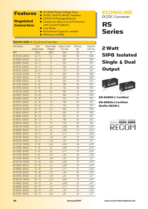
ECONOLINEDC/DC-Converterwith 3 year WarrantyRSO E-95REV:1/2011EN-60950-1 Certified EN-60601-1 CertifiedDescriptionHigh-power-density, an industrial temperature range of -40°C to +85°C and extra features like On-Off-control are just some of the characteristics of this converter, ideal for highly sophisticated industrial-designs. The RSO series is available with isolation of 2kV or 3kV by chosing option "/H2"or "/H3" in which case it is also ideal for medical applications which additionally require EN-60601-1 certification. The standard version offers 2:1 input voltage range, while the “Z” version features 4:1input voltage range, which includes an input voltage range covering both 5V and 12V supplies.1 WattSIP8 Isolated Single &Dual Output●2:1 and 4:1 Wide Input Voltage Ranges ●1kVDC, 2kVD or 3kVDC Isolation ●UL94V-0 Package Material●Certified for Medical Applications ●Continuous Short Circuit Protection ●Low Noise●No External Capacitor needed ●Efficiency to 83%FeaturesRegulated ConvertersSelection GuidePart NumberInput Rated Output Output Current Efficiency Max Voltage Range Voltage typ.CapacitiveSIP8(VDC)(VDC)(mA)(%)Load (1)RSO-xx3.3S* 4.5-9**, 9-18 3.330068-723300µF18-36, 36-7270RSO-xx05S* 4.5-9**, 9-18520073-751200µF18-36, 36-7275-78RSO-xx09S* 4.5-9**, 9-18911174-78680µF18-36, 36-7278-81RSO-xx12S* 4.5-9**, 9-18128375-80680µF18-36, 36-7280-83RSO-xx15S* 4.5-9**, 9-18156775-80680µF18-36, 36-7280-83RSO-xx3.3D* 4.5-9**, 9-18±3.3±15068-72±1500µF18-36, 36-7270RSO-xx05D* 4.5-9**, 9-18±5±10073-75±470µF18-36, 36-7275-76RSO-xx09D* 4.5-9**, 9-18±9±5674-78±470µF18-36, 36-7278RSO-xx12D* 4.5-9**, 9-18±12±4275-79±330µF18-36, 36-7279-80RSO-xx15D* 4.5-9**, 9-18±15±3475-79±330µF18-36, 36-7279-80RSO-xx3.3SZ*9-36 3.330068-703300µF18-7270RSO-xx05SZ* 4.5-18**, 9-36520073-781200µF18-7275RSO-xx09SZ* 4.5-18**, 9-36911175-81680µF18-7278RSO-xx12SZ* 4.5-18**, 9-36128377-83680µF18-7280RSO-xx15SZ* 4.5-18**, 9-36156778-83680µF18-7280RSO-xx3.3DZ*9-36±3.3±15070-74±1500µF18-7270RSO-xx05DZ* 4.5-18**, 9-36±5±10073-77±470µF18-7275RSO-xx09DZ* 4.5-18**, 9-36±9±5674-78±470µF18-7278RSO-xx12DZ* 4.5-18**, 9-36±12±4275-80±330µF18-7280RSO-xx15DZ* 4.5-18**, 9-36±15±3475-80±330µF18-7280No suffix is standard isolation (1kVDC) e.g, RSO-0505S*add suffix /H2 or /H3 for 2kVDC or 3kVDC isolation, e.g, RSO-0505S/H2, RSO-0505DZ/H3** derate to 75% if Vin<5V, 12V 4:1 input also requires an external 10µF input capacitor.Refer to Application NotesRoHS2002/95/EC6/6O u t p u t P o w e r (%)100602040Operating Temperature °C80Derating-Graph(Ambient T emperature)2:1Input 4:1Input (RS0-S/D) (RSO-SZ/DZ)xx = 4.5-9Vin = 05 xx = 4.5-18Vin = 12xx = 9-18Vin = 12 xx = 9-36Vin = 24 xx = 18-36Vin = 24 xx = 18-72Vin = 48xx = 36-72Vin = 48/E-96REV: 1/2011R S 0Input Voltage Range 2:1 and 4:1Output Voltage Accuracy ±2% typ.Line Voltage Regulation 2:1±0.2% max.4:1±0.5% max.Load Voltage Regulation 2:1±0.4% max.(10% to 100% full load)4:1±0.5% typ.Minimum Load0%Output Ripple and Noise (20MHz limited)50mVp-p max.Operating Frequency 2:1200kHz min. / 500kHz max.4:1100kHz min. / 800kHz max.Efficiency at Full Load See Selection GuideQuiescent Current RSO-05xxS_D, SZ_DZ 40mA typ.Nominal input Voltage RSO-12xxS_D32mA typ.(Standard, /H2 and /H3)RSO-24xxS_D, SZ_DZ 25mA typ.RSO-48xxS_D, SZ_DZ15mA typ.CTRL Pin drive current /see Notes)3mA typ, 6mA max.Quiescent Input Current when Converter is OFF 10mA max.Isolation Voltage Standard (tested for 1 second)1000VDC(rated for 1 minute)500VAC / 60Hz/H2 Version (tested for 1 second)2000VDC(rated for 1 minute)1000VAC / 60Hz/H3 Version (tested for 1 second)3000VDC(rated for 1 minute)1500VAC / 60HzIsolation Capacitance Standard 2:1 Single 10pF min. / 40pF typ. / 60pF max.Isolation Capacitance /H2 and /H32:1 Single 5pF min. / 30pF typ. / 60pF max.Isolation Capacitance Standard 2:1 Dual 120pF min. / 170pF typ. / 250pF max.Isolation Capacitance /H2 and /H32:1 Dual 5pF min. / 30pF typ. / 60pF max.Isolation Capacitance Standard 4:1 Single/Dual 200pF max.Isolation Capacitance /H2 and /H34:1 Single/Dual 30pF max.Isolation Resistance >1G Ωmin.Short Circuit ProtectionContinuousOperating Temperature Range (free air convection)-40°C to +85°C (see Graph)Storage Temperature Range -55°C to +125°CRelative Humidity 95% RH Package Weight 4.7gPacking Quantity 22 pcs per TubeMTBF (+25°C)using MIL-HDBK 217F 1685 x 103 hours (+85°C)using MIL-HDBK 217F254 x 103 hoursSpecifications (Core Operating Area)measured at T A = 25°C, nominal input voltage, full load and after warm-up time unless otherwise specifiedTypical ApplicationE f f i c i e n c y %100040%0%100%40Efficiency / Load 60%80%20%206080Total Output current (%)RSO-24xxS}Detailed Information seeApplication Notes chapter "MTBF"-Vin-Vout+Vout+VinE f f i c i e n c y %100040%0%100%40Efficiency / Load 60%80%20%206080Total Output current (%)RSO-1205SZ/RSO E-97REV:1/20113rd angleprojection8 PIN SIP PackageXX.X ± 0.5 mm XX.XX ± 0.25 mmPin 8 (NC*)This pin is used internally and must have no external connection.Pin 5 (NC)Not connected internally.Pin 3 (CTRL)This pin provides an Off function which puts the converter into a low power mode. When the pin is ‘high’ the converter is OFF and when the pin is high ‘Z’ the converter is ON. There is no allowed low state for this pin.Package Style and Pinning (mm)Single Output Recommended Footprint DetailsPin Connections Pin #SingleDual1 –Vin –Vin2 +Vin +Vin 3CTRL CTRL 5NC NC 6+Vout +Vout7 –Vout C om8NC*–VoutNC = No ConnectionNC* = NC, but no external Connection allowed.CTRL Examples+VoutCtrlTTL Remote CTRL CircuitVoltage to be applied via a limiting resistor with a recom-mended value of 1K for RSO-05xx; 3.3K for RSO-12xx;4.7K for RSO-24xx and 10K for RSO-48xx.Control Pin Input Current: 10mA Voltage Set Point Accuracy with external input/outputcapacitors refer to typ. ± 1%recommended test circuit: max. ±2%Control Pin (CTRL) Input Current, control voltage applied via 1K resistor,output voltage must typ. 3mA reduce to 0V: max. 6mA+VoutIsolated Remote CTRL CircuitNotes Note 1Maximum capacitive load is defined as the capacitive load that will allow start up in under 1 second without damage to the converterCertifications EN General Safety Report: IL-R7109EN60950-1:2001 + A11:2004EN Medical SafetyReport: PS071001601EN60601-1:1990 + A11:1996/分销商库存信息:RECOM-POWERRSO-0505S RSO-0505D RSO-2412DZ RSO-2405SZ/H3RSO-243.3S RSO-1212S RSO-2412D RSO-2415D RSO-0505S/H2 RSO-2405SZ/H2RSO-2405DZ RSO-0505S/H3 RSO-2412SZ/H3RSO-1205DZ RSO-1212DZ RSO-2415DZ/H3RSO-2412DZ/H3RSO-4812SZ/H3 RSO-4805SZ/H3RSO-4812DZ/H3RSO-4815DZ/H3 RSO-2409S RSO-1209S RSO-1215S RSO-123.3S RSO-2415S RSO-2412S RSO-2405S RSO-0509S RSO-0512S RSO-053.3S RSO-2409SZ RSO-2412SZ RSO-2415SZ RSO-243.3SZ RSO-4805S RSO-4809S RSO-4812S RSO-4815S RSO-483.3S RSO-1205S RSO-0509D RSO-0509S/H2RSO-0512D RSO-0512S/H2 RSO-0515D RSO-0515S/H2RSO-053.3D RSO-053.3S/H2RSO-2409DZ RSO-2409SZ/H2 RSO-2412SZ/H2RSO-2415DZ RSO-2415SZ/H2 RSO-243.3DZ RSO-243.3SZ/H2RSO-1205S/H3 RSO-1209S/H3RSO-1212S/H3RSO-1215S/H3 RSO-123.3S/H3RSO-2405S/H2RSO-2409S/H2 RSO-2412S/H2RSO-2415S/H2RSO-243.3S/H2 RSO-2405D RSO-2409D RSO-243.3D RSO-2405D/H2RSO-2409D/H2RSO-2412D/H2 RSO-2415D/H2RSO-243.3D/H2RSO-1205S/H2 RSO-1209S/H2RSO-1212S/H2RSO-1215S/H2 RSO-123.3S/H2RSO-1205D RSO-1209D RSO-1212D RSO-1215D RSO-123.3D RSO-0515S RSO-2405SZ RSO-1209SZ RSO-1215SZ RSO-123.3SZ RSO-0509S/H3 RSO-0512S/H3RSO-0515S/H3RSO-053.3S/H3 RSO-1205D/H2RSO-1209D/H2RSO-1212D/H2 RSO-1215D/H2RSO-123.3D/H2RSO-2409SZ/H3 RSO-2415SZ/H3RSO-243.3SZ/H3RSO-1205SZ/H2 RSO-1209DZ RSO-1209SZ/H2RSO-1212SZ/H2 RSO-1215DZ RSO-1215SZ/H2RSO-123.3DZ RSO-123.3SZ/H2RSO-4805SZ RSO-4809SZ RSO-4812SZ RSO-4815SZ RSO-483.3SZ RSO-2409S/H3RSO-2412S/H3RSO-2415S/H3 RSO-243.3S/H3RSO-2405D/H3RSO-2409D/H3 RSO-2412D/H3RSO-2415D/H3RSO-243.3D/H3 RSO-4805D RSO-4805S/H2RSO-4809D RSO-4809S/H2RSO-4812D RSO-4812S/H2 RSO-4815D RSO-4815S/H2RSO-483.3D。
CONTENTS1 GENERAL DESCRIPTIONS (3)2 ABSOLUTE MAXIMUM RATINGS (4)3 ELECTRICAL SPECIFICATIONS (5)4 OPTICAL CHARACTERISTICS (6)5 PIXEL FORMAT (10)6 OUTLINE SIZE (11)7 CELL LIGHT-ON INFORMATION (16)8 RELIABILITY CONDITION (20)9 IVO RECOMMENDED CELL PACKAGING (21)10 GENERAL PRECAUTION (22)1 General Descriptions1.1 IntroductionThe C054SWZ5 is a color active matrix thin film transistor (TFT) liquid crystal display (LCD) Single Chip and Sub Chips that uses amorphous silicon TFT as aswitching device. This TFT LCD panel has a 5.46-inch diagonally measured activedisplay area with qHD resolution (540 horizontal by 960 vertical pixels array).2 Absolute Maximum Ratings3 Electrical Specifications4 Optical CharacteristicsThe optical characteristics are measured under stable conditions as following notes.Note (1) Measurement Setup: The LCD module should be stabilized at given temperature(25°C ) for 15 minutes to avoid abrupt temperature change during measuring. In order to stabilize the luminance, the measurement should be executed after lighting backlight for 15 minutes in a windless room.θy- =90°6 o ’clockFigure 2 Definition of Viewing AngleNote (3) Definition Of Contrast Ratio (CR)The contrast ratio can be calculated by the following expressionContrast Ratio (CR) = L255 / L0L255: Luminance of gray level 255, L0: Luminance of gray level 0Figure 4 C-Light SpectrumNote (7) The Normal polarizer type: TBD/CF, TBD/Array.Note (8) All optical data based on IVO given polarizer & C-light& testing machine in this document. Note (9) Polarizer DirectionFigure 5 Polarizer Direction5 Pixel FormatThe figure shows the relationship of the input signals and LCD panel pixel format.6 Outline Size6.1 Outline Size of Single ChipUnit:mmFigure 7 Outline Size of Single Chip6.2 IC / FPC Position Size On CellOTM9605A 780 1270 21815 21815 950 27150Unit:umFigure 8 IC Position InformationUnit:mm Figure 9FPC Position Information6.3 Outline Size of Sub Chips and Cut MarkSub A:Unit:mmFigure 10Outline Size of Sub ASub B:Unit:mmFigure 11Outline Size of Sub BSingle ChipUnit:mmFigure 12 Outline Size of Single Chip7 Cell Light-On Information7.1 Cell Light-On Test Pad DrawingUnit: mmFigure 13 Cell Light-On Test Pad Drawing7.2 The Distance Between silver paste and Bonding areaUnit: um Figure 14 The Distance Between silver paste and Bonding area7.3 The silver paste to the pad or Bonding MarkUnit: um Figure 15 The silver paste to the pad or Bonding Mark7.4 Cell Light-On Test WaveformFigure 16 Cell Light-On Test Waveform7.5 FPC Pin AssignmentFigure 17 FPC Pin Assignment8 Reliability ConditionTable 5Reliability Condition9 IVO Recommended Cell PackagingTBD10 General Precaution10.1 Use RestrictionThis product is not authorized for use in life supporting systems, aircraft navigation control systems, military systems and any other application where performance failure could belife-threatening or otherwise catastrophic.10.2 Handling Precaution(1) Since the LCD panel is made of glass, do not apply strong mechanical impact or static load onto it. Handling with care since shock, vibration, and careless handling may seriously affect the product. If it fall a high place or receives a strong shock, the glass maybe broken.(2) Use fingerstalls of soft gloves in order to keep clean display quality, when persons handle the LCD for incoming inspection or assembly.(3) When the surface is dusty, please wipe gently with absorbent cotton or other soft material.(4) Wipe off saliva or water drops as soon as possible. If saliva or water drops contact with polarizer for a long time, they may causes deformation or color fading.(5) When cleaning the adhesives, please use absorbent cotton wetted with a little petroleum benzine or other adequate solvent.10.3 Storage Precaution(1) Please do not leave cell in the environment of high humidity and high temperature for longtime.(2) IVO suggests to assembly the panel to LCD module in one month after cut into single chip.(3) The cell should be stored in a dark place .Store in an ambient temperature of 5°C to45°C,and in a relative humidity of 40%RH to 60%RH.Don’t expose to sunlight or fluorescent light.(4) Storage in a clean environment, free from dust, active gas, and solvent.(5) Store in anti-static electricity container.(6) Store without any physical load.10.4 Caution For Operation(1) The polarizer on the surface of panel are made from organic substance. Be very careful for chemicals not to touch the polarizer or it leads the polarizer to be deteriorated.(2) Dot drop water or any chemicals onto the LCD panel surface.(3) Please do not leave LCD panel in the environment of high humidity and high temperature fora long time.(4) Do not connect or disconnect the LCD panel to or from the system when power is on.(5) When expose to drastic fluctuation of temperature(hot to cold or cold to hot),the LCD panel may be affected; specifically, drastic temperature fluctuation from cold to hot, produces dew on the LCD panel surface which may affect the operation of the polarizer and the LCD panel.(6) Do not display the fixed pattern for a long time because it may develop image sticking due to the LCD panel structure.(7) The temperature of baking should be under 85℃.10.5 Static Electricity(1) Protection film must remove very slowly from the surface of LCD panel to prevent from electrostatic occurrence if the LCD panel attaches a polarizer.(2) Because TFT-LCD panel is very weak to electrostatic discharge, please be careful with electrostatic discharge. Persons who handle the LCD panel should be grounded through adequate methods.10.6 Safety(1) For the crash damaged or unnecessary LCD panel, it is recommended to wash off liquid crystalby either of solvents such as acetone and ethanol an should be burned up later.(2) In the case the LCD panel is broken, watch out whether liquid crystal leaks out or not. If your hands touch the liquid crystal, wash your hands cleanly with water an soap as soon as possible.(3) If you should swallow the liquid crystal, first, wash your mouth thoroughly with water, then drink a lot of water and induce vomiting, and then, consult a physician.(4) If the liquid crystal should get in your eyes, flush your eyes with running water for at least fifteen minutes.(5) If the liquid crystal touches your skin or clothes, remove it and wash the affected part of your skin or clothes with soap and running water.10.7 DisposalWhen disposing LCD panel, obey the local environmental regulations.。