GES-500系列储能双向变流器说明书(0SF.466.000)_V1.11
- 格式:pdf
- 大小:1.72 MB
- 文档页数:48

The Mobius ® Power MIX 100, 200 and 500 combine high performance mixingtechnology with easy-to-use design features. The impeller design and motor feature our proven magnetically coupled NovAseptic ® mixing technology to efficiently mix the most challenging buffers, media, and biopharmaceutical ingredients.Mobius ®Power MIX 100,200 and 500 Single-Use MixersHigh performance mixing technology and ergonomic design featuresFeatures and benefits:• Powerful magnetically coupled impeller designed to efficiently mix the most challenging buffer, media, and biopharmaceutical ingredients • Available in both plastic and jacketed stainless steel for flexibility in biomanufacturing • Broad working volume, from a minimum volume that is approximately 20% of the working volume (size dependent) with maximum volume of 10% over the working volume, for processing flexibility • Doors that open to one half the mixer's diameter for easy bag loading • Stainless steel versions include integrated load cells and temperature sensor • In-process pH and conductivity measurement option • Closed, sterile, and zero deadleg sampling directly from the mixing bag • Monitor & control remotely with Ready To Connect control box • Data collection with 21 CFR Part 11 compliant Chart Recorder optionSpecification SheetThe life science business of Merck operates as MilliporeSigma in the U.S. and Canada.2SpecificationsTank 304L stainless steel 304L stainless steel 304L stainless steel Stand 304L stainless steel 304L stainless steel 304L stainless steel Latch 18-8 stainless steel 18-8 stainless steel 18-8 stainless steel Casters 304 SS with hi-temp Phenolic wheel 304 SS with hi-temp Phenolic wheel 304 SS with hi-temp Phenolic wheel Dimensions L X W 41 x 32 in.(1030 x 810 mm)45 x 37 in.(1140 x 940 mm)55 x 47 in.(1390 x 1190 mm)Height 52 in. (1310 mm)53 in. (1340 mm)62 in. (1560 mm)Weight550 lb (250 kg)720 lb (327 kg)920 lb (417 kg)Minimum working volume (to cover the impeller)10 L 20 L 50 L Minimun sampling volume 20 L 40 L 100 L Maximum working volume 110 L220 L550 LFluid volume in jacket (approx.) 1.2 gal (4.5 L) 1.9 gal (7.2 L)3.5 gal (13.2 L)Heat transfer area of jacket (approx.)7.6 sq. ft (.71 sq. m)12.1 sq. ft (1.1 sq. m)22.7 sq.ft (2.1 sq. m)Maximum operating pressure of jacket90 psi (6.2 bar)90 psi (6.2 bar)90 psi (6.2 bar)Stainless Steel Jacketed Mixers ASME U-1 code stamped OptionalOptionalOptionalMettler-Toledo SWB505 MultiMount™ Load Cells (qty 3)*0–120 kg ±1% FS 0–240 kg ±1% FS 0–600 kg ±1% FS Load Cell Ingress protection rating IP 68IP 68IP 68RTD Temperature Sensor JUMO 0–60 °C ± 1°C 0–60 °C ± 1°C 0–60 °C ± 1°C pH Sensor Hamilton**0–14 pH ±0.1 pH0–14 pH ±0.1 pH0–14 pH ±0.1 pHConductivity Sensor Hamilton**0.2–200 mS/cm ±10% FS 0.2–200 mS/cm ±10% FS 0.2–200 mS/cm ±10% FS Storage temperature 0–40 °C (non-condensing environment)0–40 °C (non-condensing environment)0–40 °C (non-condensing environment)Operating temperature4–60 °C (non-condensing environment)4–60 °C (non-condensing environment)4–60 °C (non-condensing environment)* I ncluded with carriers compatible with Ready To Connect control boxAvailable as an option with the carriers compatible with standard control box ** Only available as an option with the Ready To Connect control boxThe following components are appropriate for the 100 L, 200 L, and 500 L models, both in stainless steel and plastic formatsAdapters SterilEnz™ LDPELuer plugs Kynar® Polyvinylidene FluorideConnectivity CPC® PolysulfoneTubing SiliconePinch clamp PVDFImpeller Neodymium magnets encased in polypropylenePowder port PolyethyleneTC gasket SiliconeTC clamp NylonTC end cap PolypropyleneCup HDPEProbe port HDPEO-ring SiliconePlug PolypropyleneNeedle-free sample port HDPEO-ring SiliconeConductivity and pH sensor (multi-use)EPDM and stainless steel 316L*Maximum operating speed has to be validated for each process and is dependent on volume, viscosity, etc.3Ordering InformationMobius® Power MIX Carriers with standard control boxPlease refer to spare parts list MK_CA7420EN (available on ) 4Single-Use assemblies to fit Mobius®Power MIX Carriers with standard control box100 L PureFlex™MXRA0100B4√Bronze411111121 MXRL0100B4√Bronze4121PureFlex™PlusMXRA0100GPL4√Gold411111121MXRA0100BPL4√Bronze411111121MXRL0100BPL4√Bronze4121200 L PureFlex™MXRA0200G4√Gold411111121MXRA0200B4√Bronze411111121MXRL0200B4√Bronze4121PureFlex™PlusMXRA0200GPL4√Gold411111121MXRA0200BPL4√Bronze411111121MXRL0200BPL4√Bronze4121500 L PureFlex™MXRA0500G2√Gold21121121MXRA0500B2√Bronze21121121MXRL0500B2√Bronze2121PureFlex™PlusMXRA0500GPL2√Gold21121121MXRA0500BPL2√Bronze21121121MXRL0500BPL2√Bronze2121Example of 200 L single-use assembly5Ordering InformationMobius® Power MIX Carriers with Ready To Connect control boxPlease refer to spare parts list MK_CA7420EN (available on ) 6Single-Use assemblies to fit Mobius®Power MIX Carriers with Ready To Connect control box100 L PureFlex™SMXRA0100LS4M√Silver411111112SMXRA0100LB4M√Bronze411111112SMXRL0100LB4M√Bronze4112PureFlex™PlusSMXRA0100LGPL4M√Gold411111112SMXRA0100LSPL4M√Silver411111112SMXRA0100LBPL4M√Bronze411111112SMXRL0100LBPL4M√Bronze4112200 L PureFlex™SMXRA0200LG4M√Gold411111112SMXRA0200LS4M√Silver411111112SMXRA0200LB4M√Bronze411111112SMXRL0200LB4M√Bronze4112PureFlex™PlusSMXRA0200LGPL4M√Gold411111112SMXRA0200LSPL4M√Silver411111112SMXRA0200LBPL4M√Bronze411111112SMXRL0200LBPL4M√Bronze4112500 L PureFlex™SMXRA0500LG2M√Gold21121112SMXRA0500LS2M√Silver21121112SMXRA0500LB2M√Bronze21121112SMXRL0500LB2M√Bronze2112PureFlex™PlusSMXRA0500LGPL2M√Gold21121112SMXRA0500LSPL2M√Silver21121112SMXRA0500LBPL2M√Bronze21121112SMXRL0500LBPL2M√Bronze2112Example of 500 L single-use assembly7Lit. No. SP1800EN00 Ver. 9.03185905/2021© 2021 Merck KGaA, Darmstadt, Germany and/or its affiliates. All Rights Reserved. Merck, the vibrant M, Millipore, Mobius, NovAsepti andPureFlex are trademarks of Merck KGaA, Darmstadt, Germany or its affiliates. All other trademarks are the property of their respective owners. Detailed information on trademarks is available via publicly accessible resources.Merck KGaAFrankfurter Strasse 250 64293 Darmstadt, GermanyFor more information, please visit 。
追日电气微电网储能逆变装置系列产品操作与
技术手册
The document was finally revised on 2021
微电网储能逆变装置系列产品操作与技术手册
上海追日电气有限公司
SHANGHAI SURPASS SUN ELECTRIC CO.,LTD
目录
---有电危险
➢
导电尘埃及气体可能损坏设备,必须确保本装置安装在没有导电尘埃的环璄中。
N
必须严格按照电气设备的相关装卸、运输要求进行操作,以下情况可能导致内部精N
如果需要在供电系统带电状态下接入
处于短接状态,防止产生高压危及人身安全和损坏设备。
服务体系与联系方式
为客户提供全过程、超过期望值的优良服务,是追日电气质量体系的核心理念。
我们的承诺是:服务永无止境。
为此,我们建立起覆盖全国的服务网络,以便我们的客户在任何时间、任何地点都能与我们快捷、高效地沟通,从而能够为客户提供售前、售中和售后的全过程真诚贴心服务。
对国内或国外顾客的要求,24小时提供满意的答复(通讯、通邮允许条件下);对国内用户的产品服务:保修期内需要进行维修或更换时,省内24小时、全国48小时派出技术人员;保修期外需进行维修或更换时,省内48小时,全国72小时出技术人员;对国外用户的产品服务;在办妥出国手续后72小时派出技术人员。
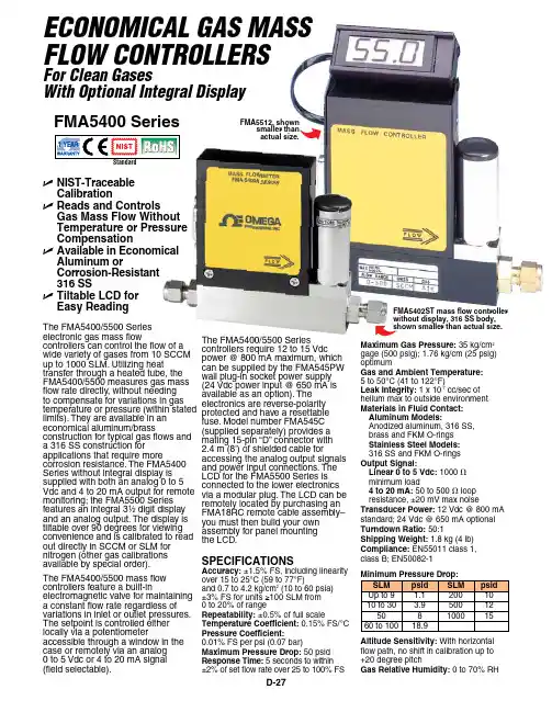
D-27SPECIFICATIONS Accuracy: ±1.5% FS, including linearity over 15 to 25°C (59 to 77°F)and 0.7 to 4.2 kg/cm 2 (10 to 60 psia) ±3% FS for units ≥100 SLM from 0 to 20% of rangeRepeatability: ±0.5% of full scaleTemperature Coefficient: 0.15% FS/°C Pressure Coefficient: 0.01% FS per psi (0.07 bar)Maximum Pressure Drop: 50 psid Response Time: 5 seconds to within ±2% of set flow rate over 25 to 100% FSThe FMA5400/5500 Series electronic gas mass flow controllers can control the flow of a wide variety of gases from 10 SCCM up to 1000 SLM. Utilizing heat transfer through a heated tube, the FMA5400/5500 measures gas mass flow rate directly, without needing to compensate for variations in gas temperature or pressure (within stated limits). They are available in an economical aluminum/brass construction for typical gas flows and a 316 SS construction for applications that require more corrosion resistance. The FMA5400 Series without integral display is supplied with both an analog 0 to 5 Vdc and 4 to 20 mA output for remote monitoring; the FMA5500 Series features an integral 3¹⁄₂ digit display and an analog output. The display is tiltable over 90 degrees for viewing convenience and is calibrated to read out directly in SCCM or SLM for nitrogen (other gas calibrationsavailable by special order).The FMA5400/5500 mass flowcontrollers feature a built-inelectromagnetic valve for maintaining a constant flow rate regardless of variations in inlet or outlet pressures. The setpoint is controlled either locally via a potentiometeraccessible through a window in the case or remotely via an analog 0 to 5 Vdc or 4 to 20 mA signal (field selectable).The FMA5400/5500 Series controllers require 12 to 15 Vdc power @ 800 mA maximum, which can be supplied by the FMA545PW wall plug-in socket power supply (24 Vdc power input @ 650 mA is available as an option). The electronics are reverse-polarity protected and have a resettable fuse. Model number FMA545C (supplied separately) provides a mating 15-pin “D” connector with 2.4 m (8') of shielded cable for accessing the analog output signals and power input connections. The LCD for the FMA5500 Series is connected to the lower electronics via a modular plug. The LCD can be remotely located by purchasing an FMA18RC remote cable assembly–you must then build your own assembly for panel mounting the LCD.Economical Gas mass Flow conTRollERsFor clean Gaseswith optional integral DisplayMaximum Gas Pressure: 35 kg/cm 2 gage (500 psig); 1.76 kg/cm (25 psig) optimumGas and Ambient Temperature: 5 to 50°C (41 to 122°F)Leak Integrity: 1 x 10⁻⁷ cc/sec of helium max to outside environment Materials in Fluid Contact: Aluminum Models:Anodized aluminum, 316 SS, brass and FKM O-rings Stainless Steel Models: 316 SS and FKM O-rings Output Signal:Linear 0 to 5 Vdc: 1000 V minimum load4 to 20 mA: 50 to 500 V loop resistance, ±20 mV max noiseTransducer Power: 12 Vdc @ 800 mA standard; 24 Vdc @ 650 mA optional Turndown Ratio: 50:1Shipping Weight: 1.8 kg (4 lb)Compliance: EN55011 class 1, class B; EN50082-1Altitude Sensitivity: With horizontal flow path, no shift in calibration up to +20 degree pitchGas Relative Humidity: 0 to 70% RHFMA5402ST mass flow controller without display, 316 SS body, shown smaller than actual size.FMA5512, shownsmaller than actual size.U NIST-Traceable CalibrationU Reads and Controls Gas Mass Flow Without Temperature or Pressure CompensationU Available in Economical Aluminum orCorrosion-Resistant 316 SSU Tiltable LCD for Easy ReadingFMA5400 SeriesD-28D* Comes with 3⁄4 FNPT connections instead of compression fittings.Comes complete with compression fittings, NIST certificate and operator’s manual. Power supplies sold separately.Flow ranges specified are for nitrogen or air at 20 psig inlet (up to 50 SLM) or 25 psig inlet 60 to 100 SLM units) and 0 psig outlet. When used with other gases, a multiplication factor is used to determine the flow rate, and the digital display must be rescaled in the field.To request a custom calibration add the gas abbreviation and inlet pressure/outlet pressure as a suffix to the model number.Calibration are done at ambient temperatures only, 20ºC (70ºF)For 24 Vdc powered units, add suffix “-24VDC” to the model number, no additional cost.For oxygen cleaned units, add suffix “02CLEAN” to model number for additional cost.Ordering Examples: FMA5410–ARGON , 50/0 psig, 70°F calls for an AL/BR body flow controller without an integral display, calibrated for Argon at 50 psig inlet pressure, 0 psig outlet pressure, 70°F gas temperature, powered by 12 Vdc.FMA5516, N 2 controller with display, and FMA545PW , power supply.FMA5512, shown smallerthan actual size.。

S-500 Snow MachineUser ManualEnglish©2016 Antari Lighting and Effects Ltd.User ManualPlease read the following safety information carefully before operating themachine. Information includes important safety information about installation,usage, and maintenance. Pay attention to all warning labels and instructions inthis manual and printed on the machine.If you have questions about how to operate the machine safely, please contact your local Antari dealer for help.․Keep this device dry.․Always connect to a grounded circuit to avoid risk of electrocution.․Before connecting machine to power, always check voltage indicate on machine match to your local AC voltage. Do not use the machine if AC power voltage does not match. ․Disconnect the machine from AC power before servicing and when not in use.․This product is for indoor use only! Do not expose to rain or moisture. If fluid is spilled, disconnect AC power and clean with a damp cloth. If fluid is spilled onto electronic parts, immediately unplug the machine and contact your local Antari dealer for advice.․No user serviceable and modifiable parts inside. Never try to repair this product, unauthorized technician may lead machine to damage or malfunction.․For adult use only. Never leave the machine running unattended.․Installed in well ventilated area. Provide at least 50 cm space around the machine.․Never add flammable liquid of any kind to the machine.․Make sure there are no flammable materials close to the machine while operating.․Only use Antari fluid. Other fluid may lead to heater clog and malfunction.․If the machine fails to work, unplug the machine and stop operation immediately.Contact your local Antari dealer for advise.․Before transporting the machine, make sure the fluid tank is completely drained.․Smoke fluid may present health risks if swallowed. Do not drink smoke fluid. Store it securely. In case of eye contact or if fluid is swallowed immediately look for medical advice.Immediately upon receiving the machine, carefully unpack the carton, check all content to ensure that all parts are present and have been received in good condition. If any parts appear damaged or mishandled from shipping, notify the shipper immediately and retrain the packing material for inspection.What is included: 1 x S-500 Snow Machine1 x Power Cord1 x User Manual592 mm651 mm551 mmStep 1: Place the machine on a flat surface and in a suitable large area with at least 50 cm open space around the machine.Step 2: Fill the fluid tank with Antari approved fluid.Step 3: Connect the machine to suitable rated power supply. To determine the power requirement for the machine refer to the label on the back of the machine.Always connect the machine to a protected circuit and ensure it is properly grounded to avoid risk of electrocution.Step 4: Turn on the machine, press the [VOLUME]/[DOWN] button on the control panel to start making snow.Step 5: To turn off the machine, press the [STOP] button and put the power switch to the OFF position.Control Panel OperationThe machine can be operated with onboard digital control interfacePM-1 Pan Motor (Optional)Control MenuSet interval time at timer mode from 15 to 360 secSet duration time at timer mode from 5 to 120 secSet output volume at timer mode from 1 to 100%Set output volume at volume mode from 1 to 100%Set fan speed from 20 to 100%Set DMX/W-DMX address from 1 to 511Timer IntervalXXX SecTimer DurationXXX SecTimer OutputXXX %Volume OutputXXX %Fan SpeedXXX %DMX-512Address: XXXTurn On/Off W-DMX functionUnlink from W-DMX transmitterTurn On/Off wireless remotePair/Unpair with wireless remote.*This menu will not be shown when Wireless is turn Off.Turn On/Off run last setting functionDMX Connector Pin AssignmentThe machine provide 3 or 5 pin XLR connector for DMX connection. Diagram below indicatepin assignment informationDMX OperationMaking the DMX Connection – Connect machine to a DMX controller or to one of the machines in the DMX chain. The machine uses an 3-pin XLR connector for DMX connection,W-DMX PowerXXW-DMX ResetXXWireless Register Up:Pair Down:Del Run Last SettingXXWirelessXXthe connector is located on the rear of the machine.Address Setup – Use control menu to set DMX address. The machine occupies 2 control channels. The starting address is defined as the first channel from which the machine will respond to the controller. Always double check to make sure there are no overlapping channels in order to control the machine correctlyDMX Channel FunctionWireless Remote Operation (Optional)Wireless remote control system W-2 consist of a transmitter equipped with two buttons to activate, deactivate and adjust output level; with an onboard receiver attach to the front panel of S-500 snow machine.W-2 Wireless TransmitterWireless ReceiverIn a free open space the effective distance is 50 meters, actual usage depending on obstacle level the effective distance is 10-25 meteres.Registering a transmitterTransmitter can be pair or deleted from the receiver. Each receiver can pair up to 10 transmitters. Follow below diagram to pair or delete transmitter.IMPORTANT NOTE: Wireless register menu will only be shown when Wireless is turn ONTransmmiter battery replacementIf effective distance seems to be decreased, it is possible the battery level are low and require replacement. In order to replace the battery, undo the three screws on the back of transmitter to release the cover. Replace with same type and specification of battery which is 27A 12V.Wire remote Operation (Optional)Wire remote control module SC-3 enable to control the machine from a remote location. With three push button and two rotary knob to activate/deactivate, priming and output level adjustment.IMPORTANT NOTE:[LEFT BUTTON] is meant for priming use,with a new tank of fluid or refill the fluid may not pump properly due to airlock in the pipeline, use this function to activate pump at maximum output, the [RIGHT BUTTON] is used when needed to clean out residue on the tip of outputnozzle. Both of these button will overtake output adjustment knobs.Physical InstallationImportant●Use supplied mounting bracket or rigging clamp to install nozzle.●Maksure installation location, fastening connecting, and rigging hardware can hold atleast 10 times the weight of the nozzle.●Make sure no combustible or flammable material nearby.●Secure nozzle with an approved safety cable that can hold at least 10 times the weightof nozzle.●Make sure nozzle installed in a well ventilated area.●Consider nozzle replacement and routine maintenance access when selectinginstallation location.Adjustable Moutning BracketAdjust mounting bracket by loosening screws, set the nozzle to desire angle and tighten the screw to finish adjustment. Illustration below demostrates how to adjust mounting bracket.MountingUse screws for surface mounting or clamps for truss mounting.Air Hose Extension (Optional)The maximum air hose length is 20 meters. Illustration below demostrates how to connect extension air hoseOnly use Antari SL-5/SL-5A liquid for the S-500 Snow Machine. The machine is tested and calibrated with this liquid to get the best output performance. Warranty will be void if any other type of liquid is used, improper use of liquid may lead to machine failure and malfunction.․Do not allow the machine to become contaminated.․Remove dust from air vents with air compressor, vacuum or a soft brush.․Only use a damp cloth to clean the casing.․Before storing run distilled water through the system to help avoid condensing the pump or heater.․It is recommended to run the machine on a monthly basis in order to achieve best performance and output condition.․Excessive dust, liquid and dirt built up will degrade performance and cause overheating. ․Before storing away after operation, pump pure water through the system for at least 1 to 2 minutes. This will help clean out the remaining snow fluid and prevent pump from malfunction on next usage.Breaker ResetDisconnect AC power before reset breaker. Only replace fuse with same typeand rating.Step 1: Disconnect power cord from supply.Step 2: Flip breaker to ON position.Step 3: Turn on machine to test.Breaker120V = 10A 250V230V = 5A 250VInput voltage 120V 60Hz240V 50HzBreaker 120V = 10A 250V230V = 5A 250VPower consumption 890WMax. operating time 0.8 hrs max. outputFluid tank capacity 20L (5.28 gal)Fluid consumption 400 ml/min.Compatible fluid Antari SL-5/SL-5A snow fluidControl option DMX 512, Cable remote, Manual, WirelessAdjustable snow volume and fan speed DMX channels 2 channels, snow volume and fan speed Power connection Neutrik PowerconDMX data connection 3-pin XLR and 5-pin XLRRemote control connection 4-pin XLRDimension L 592 x W 551 x H 651 mm(L 23.31 x W 21.69 x H 25.63 inch)Dry weight 37.2 kg (82.01 lb)Accessories (Optional) SC-3 remoteST-10 Air hose extensionW-2 Wireless remoteC08S50001。

储能双向变流器hs code摘要:1.储能双向变流器的概念2.储能双向变流器的功能与作用3.储能双向变流器的应用领域4.储能双向变流器的国际编码HS code正文:储能双向变流器是一种电力电子设备,具有将直流电能与交流电能相互转换的功能。
通过储能双向变流器,可以实现电能的高效传输、分配和控制,满足各种电力系统对电能的需求。
1.储能双向变流器的概念储能双向变流器,简称SVG(Static Var Compensator),是一种基于现代电力电子技术的高科技产品。
它具有双向变流、动态无功补偿、谐波抑制等功能,广泛应用于电力系统的输电、配电、储能等环节。
2.储能双向变流器的功能与作用(1)双向变流:储能双向变流器能够实现直流电能与交流电能的相互转换,以满足不同电力系统的要求。
(2)动态无功补偿:储能双向变流器可根据电力系统的实际需求,对无功功率进行实时调节,提高电力系统的稳定性和可靠性。
(3)谐波抑制:储能双向变流器能够有效地抑制电力系统中的谐波,降低谐波对电力设备的损害,提高电能质量。
3.储能双向变流器的应用领域储能双向变流器广泛应用于以下领域:(1)风力发电:通过储能双向变流器,可以实现风力发电的稳定输出,提高电能质量。
(2)光伏发电:储能双向变流器能够将光伏发电系统产生的直流电能转换为交流电能,满足电力系统的要求。
(3)电力系统稳定:储能双向变流器在电力系统中可以实现对无功功率的动态调节,提高电力系统的稳定性和可靠性。
(4)输电线路补偿:储能双向变流器可用于输电线路的动态无功补偿,降低输电损耗,提高输电效率。
4.储能双向变流器的国际编码HS code根据国际海关编码规定,储能双向变流器的HS code为85043000。
这一编码涵盖了静态变流器、逆变器、整流器等电力电子设备。
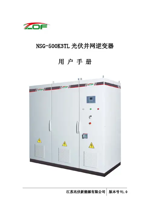
NSG-500K3TL光伏并网逆变器用 户 手 册江苏兆伏新能源有限公司 版本号V1.0目录1、绪论 (3)1.1符号解释 (3)1.2手册说明 (5)2、安全指示 (6)3、产品描述 (7)3.1系统简介 (7)3.2产品说明 (8)3.2.1产品型号说明 (8)3.2.2产品铭牌 (8)3.2.3技术参数 (9)3.2.4效率曲线 (10)3.3外观说明 (11)3.4内部连接 (12)3.4.1线缆规格 (12)3.4.2 主回路连接 (13)3.4.3 控制回路连接 (17)3.4.4 保护接地连接 (17)3.5工作模式 (18)3.6保护功能 (19)4、操作与设置 (21)4.1操作界面 (21)4.2菜单显示 (22)4.3开机与关机 (25)4.4参数设置 (26)5、故障与维护 (28)5.1故障分析 (28)5.2维护 (29)6、附录 (30)6.1质量保证 (30)6.2联系ZOF (31)1、绪论1.1 符号解释本手册使用的指示符号的含义解释如下:此标志表明如果发生将会导致伤亡或重大损坏的注意事项或操作。
此标志表明如果发生将会导致伤亡或重大损坏的注意事项或操作此标志表明如果发生将会导致伤亡或重大损坏的注意事项或操作此标志表明系统良好工作的最佳配置和操作设备上面,显示器上面或者手册里面将会使用标志来代替文字。
商标小心触电!保护接地小心触电!蓄能放电时间:20分钟!断电之后20分钟之内都会存在危险高压。
1.2 手册说明尊敬的客户,感谢您选用本公司的产品。
使用前,请您务必仔细阅读本手册。
本手册是NSG-500K3TL光伏并网逆变器用户手册,版本号V1.0。
主要介绍了江苏兆伏新能源有限公司生产的NSG-500K3TL光伏并网逆变器的产品信息及使用规范,主要包括产品的特点、外观、内部连接、功能、操作与设置以及故障诊断与维护等方面的内容。
本手册的最终解释权归江苏兆伏新能源有限公司所有,如有疑问或建议,请及时与本公司联系。


HV transformers for Tektronix 500 series scopeswound on ETD44 corebyMarco MorelliApril 2021Special thanks to Kurt Rosenfeldfor help in translation and precious suggestionsIndex500 series HV Transformers (4)Reference schematic (5)Core (6)Primary winding (7)Secondary winding (9)Windings diagram (9)HV Box (10)Testing (11)Things that are wrong (11)Second type transformer (12)Consideration on separate windings (13)Third type transformer (15)556 transformers (16)HT transformer for Tek 556 (Upper Beam) V1 (16)HT transformer for Tek 556 (Lower Beam) V1 (17)HT transformer for Tek 556 (Lower Beam) V2 (18)Tek 531A transformer (20)Tek 549 transformer (21)500 series HV TransformersIt is known that the HV transformers of the 500 series dipped in epoxy have age problems. Rewinding a new transformer is difficult to accomplish without specific means, such as “cross winders”, especially if you want to wound four wires together.The first question for restoring a 547 was whether it is possible to wind a simple-to-realize transformer made with materials of easy availability.The features had to be:1 - monofilar windings;2 - separate secondary on different layers;3 - standard windings (not crossed);4 - core ETD44;5 - wires not so thin to be difficult to stretch and wound.6 - no exotic coil former;7 - no modification to 547 original schematic;8 - no vacuum diode on high voltage.The reasons for the choice of ETD44 were simple: I had one at home and ETD44 is the only one that (mostly) fits in the HV box of 547.After a quick calculation I created a prototype that operates well and is in service since 2006. I currently have four scopes with new transformers, all working (544, 546 ,547, 556). However, not all desiderata have been respected:1 - a small modification to the HV box has been needed;2 - changes to the HV circuit, though completely trivial, turned out to be useful;3 - primary winding is bifilar (!);Two different types of windings will be presented:1 - alternate secondary windings;2 - secondary windings on different sections of the core.Some different transformers will be presented; three for the 547, the others for the 556 (Upper and Lower Beam).Reference schematicTektronix type 547 oscilloscope, Partial CRT circuit from original manual. T1 is the transformer of which a reconstruction is proposed;C808or “C_tank”, with T1 form the oscillator.CoreThe core is composed of two different ETD44 ferrites, one with a null gap, the other with 0.5mm gap (g in figure).The used material is TDK B66365G0000X127 and B66365G0500X127 (N27).1It is not necessary to use the same core, the one that matters is to have a value of Al2 not less than 400, otherwise you will not be able to keep the number of turns low.With N27 and 0.5mm gap, Al is approx. 440.1Datasheet on https:///inf/80/db/fer/etd_44_22_15.pdf2 Al is inductance factor; Al = L/N²; unit is nH.Primary windingThe winding is finished with two 0.2mm paper turns.No coil former was used.The wire is wound directly on a 15mm diameter iron cylinder, covered with 0.2mm paper. When the transformer was completely wounded, the cylinder has been removed. For some transformers, I also used a standard vertical coil former, reworked to eliminate all the parts that go into mechanical conflict with the HV box, but the electrical result does not change.--My considerations on the number of turns…It is extremely important to completely fill the surface available, and this criterion is in this case the most decisive in choosing the wire diameter (within certain limits). The result is that by winding two parallel wires of nominal 0.17mm, they will 48 turns (bifilar) will easily fit in a single layer, which is what we need. I expect a higher Rac3 than the original, but this is partially compensated by the reduction of the turns.Winding in bifilar can seem difficult, but there is only one layer, turns are few and the wire big enough not to create problems. It can be done easily.The reason behind 48 turns and not 60, as in original, is to keep the capacitance low; since not being able to wind “bee nest”, and the useful space for the windings is quite long, we will have to keep the number of interfaces4 no more than seven. In fact, in this first type of transformer, the two secondaries will be wound alternately5. Consider that the capacitance value for interfaces will be about 6pF/cm²; the capacitance between primary and secondary and between secondary and core, I didn't consider them: this because the first layer of the cathode secondary, the one adjacent to the primary, is the one directly connected to the ground. If the interfaces will be seven, things will be in order. Therefore the secondary turns must be ≈400 (with 0,17mm wire) and therefore the primary will stop at 48 turns.Obviously it would be possible to vary the number of turns if the secondary diameters are varied, keeping the interfaces and therefore the capacitances unaltered, and decreasing the induction, but there are several reasons not to do this in a prototype, including having to obtain only one gauge of wire.3Rac means resistance in AC V olt; I held the frequency of 50kHz as references.4For “interface” I mean the surface where two windings overlook each other, as were the plates of a capacitor. For this transformer the geometric average capacity is about 80pf. Being the secondary wounded after the primary and its isolation, I held a more reasonable value of 100pF. Wanting to stay under the value of 1nF, I preferred not to exceed the number of seven interfaces. Being the leakage inductance presumable in 60uH, the first resonance falls a decade above the maximum operating frequency envisaged (70kHz).5I mean the secondaries are not wounded separately, one above the other; instead they are divided into more sections which are wounded in sequence alternatively.Core specs and Al value permits6 to stop at 48 with 160Vac, without special aggravations. The primary inductance will be lower than the original, but this is not a problem, if we remain within certain limits. The gap is recovered by raising the value of C_tank, to stay in a range between 35 and 75 kHz.An inductance is expected near one mH and a 10nF tank cap to keep resonance at approximately 50 kHz.6with Al=400, g=0.5mm, material N27 and 160V ac @ 50khz, I expect an induction value < 90mT, such as to produce minimal distortions.Secondary windingWindings diagram In order not to interrupt the windings, two separate spools of 0.17mm wire have been prepared; while one was unrolled on a winding, the other remained integral with the mandrel.The insulation between layers was made with common teflon tape for plumbers of 0.076mm and a round of 0,05mm baking paper. I approximated half a turn less on the winding ends to be able to get out on the right side. The reason for putting double the insulation on the last three layers is not due to the voltage but to the saving capacitance. The two parts making up the core are held together with only two turns of tape. Finished with two-component resin.Wound without coil former.Prototypewound onstandardvertical coilformer (left).HV BoxThe new transformer fits perfectly into the box in place of the original one, except for the lid. The seats of the upper screws impact the edges of the core and therefore must be filed properly. It involves filing about two mm diagonally for each of the four seats. The work is very simple and does not compromise the box. I removed the material using an unprofessional micro-drill.To prevent the transformer from falling into the hole below it, I placed a 0.5mm piece of rigid tape, but anything stiff enough is perfect. It is not necessary to recover the pcb placed on the upper side of the old transformer to close the box.New transformer in placeTestingOne preliminary consideration: with regard to the operation of HV circuits, we can say that, all other conditions being equal, the voltage on the V800 screen grid is inversely proportional to the efficiency of the transformer. If the steady state voltage is lower than 90V (as per the diagram) then the transformer is working well.The measured voltage is 60V with the new transformer.I took the measurement with the spot stopped in the center of the screen and just visible, the time base stopped. The voltage variation with 1ms sweep triggered at 1 kHz and maximum brightness (it's blinding!) never exceed 85V .If you want you can optimize things by choosing the value of the tank capacitor in order to find the frequency where theefficiency is greater. I found ≈40kHz, looking at the V800 screen voltage: the value is pretty close to what I expected.No changes, apart from C808, have been made. To be wise, the protection circuit should be changed (R804, D804) but I didn't do it.The increase in core temperature, relative to room temperature, is negligible.Things that are wrongIf the brightness is kept very low, a slight intensity modulation in track (at the oscillator frequency) appears at times. The thing is barely perceptible (and totally asynchronous) and is not visible if the brightness is kept normal. The cause is an excessive disturbance of the oscillator, probably due to a slightly too high value of the primary induction. In the second type of transformer the thing has disappeared.Voltage at V800 anode 100V/Div.The photo was taken by the same 547with the new transformer mountedSecond type transformerCore is same as previous;the coil former is cut in two vertically;the primary is wound first (near the core), 27 turns per section; tot. 54 turns on one layer; secondary 1 (anode, cathode) is wound on one section, secondary 2 (grid) on the other;secondary => about 55 turns per layer; 2 turns of Teflon tape of thickness 0.075mm between all the layers of a single winding.F = 42,092 kHz;V oltage on the V800 screen grid is 51V .This transformer works better than all the others, but it is more difficult to build, given the two-wire secondaries.secondary windings on different sections of the coreConsideration on separate windingsAn essential consideration on transformers with separate secondaries, wound on distinct sections: the grid voltage becomes a function of the frequency!This happens because the two secondaries no longer have a close coupling and their cross capacitance is reduced to a minimum. The feedback circuit monitors the cathode voltage alone, assuming the grid follows. This is still true with this type of winding, as long as the frequency is very stable. The consequence is that some time is lost in calibrating everything. I proceeded as follows: first I found a value of that tank capacitor that provided good performance, without looking at the grid voltage. Then I readjusted the secondary grid winding to get the right voltage. Having the grid fed by a separate winding, it is quite easy to modify it. It is a matter of a few turns of difference, but it is not possible to say in advance how many, because it all depends on the winding precision that can be obtained. Despite this hassle, I prefer this type of winding. In any case it is desirable that the tank capacitor is of the NP0 silver mica type, due to the low losses and great stability. Frequency shifts of a few kHz do not cause pain. The increase of the turns in the primary has benefited.This transformer has been working on a Tek 546 since 2008 without any problems.Given the reduction in capacitance between the secondaries, one would expect that it will be necessary to check the compensation of the unblanking signal (C828, R828 etc, in diagram below). In reality, no changes were needed. The check can be done in two ways:1 - with a high voltage probe, connected directly to R850; the probe mustload the circuit very lightly, and I do not have a reliable probe for thistest.2 -Set the time base on a value of 10ms / Div., reduce the brightness to theminimum (just visible) and observe if the first part of the trace is brighterthan the rest. Also check with shorter times, for example 1us / Div.Tektronix type 547 oscilloscope partial CRT circuitsIt has never been necessary to modify these circuits with the exception of a 556 (lower beam), where a compensation has been introduced as shown in the diagram below.Third type transformerIt is also possible to wind the first type of transformer on a sectioned coil former; the result is very little different and the problem of intensity modulation in track is no longer present. Obviously the annoyance of the calibration of the grid winding remains.The core is same as previous;the coil former is cut in two vertically;the primary is wound first (near the core), 24 turns x section, tot 48 turns on one layer;the secondary1 (anode, cathode) is wound on one section, the secondary2 (grid) on the other; secondary => about 55 turns per layer;2 turns of baking paper between the layers of a single wound;about halfway through the package, a 0.2mm round of paper (for straightening).F= 42 kHz;V oltage on the V800 screen grid is 60V.This transformer has been working on a Tek 544 since 2008 without any problems.556 transformersHT transformer for Tek 556 (Upper Beam) V1Core ETD 44, air gap (total) 0.5mm (column only) (N87)The coil former is divided into 2 equal sections.The primary is wound first (near the core), starting from primary 2, contact side;Primary 1 follows on the same layer.One turn of ribbon + 2 turns of paper.The secondaries as follows:Starting from the contact side, the secondary1 is wound around 60 turns per layer;the secondary2 follows.Between all the layers 1 round of tape; about halfway through the wounds 1 turn of cardboard.F = 38KHz;unwound 5 turns from secondary 2;R1351 = 270 OhmHT transformer for Tek 556 (Lower Beam) V1Core ETD 44, air gap (total) 0.5mm (column only) (N87)First is wound the primary 2 (near the core), starting from contact side;then the primary 1;A ribbon ride + 2 paper turns follows on the same layer.Secondary alternate (like tr1) as follows:1 start secondary 1 pin 5140 turns2 start secondary 2 pin 6 140 turns3 secondary 1 140 turns4 secondary 2140 turns5 secondary 1 136 turns => TAP pin 86 secondary 2 140 turns => end pin 97 secondary 1 123 turns => end pin 7 Among all the layers => 1 ribbon turn + 1 0.2mm paper turn;Among layers 6 and 7 => 1 ribbon turn + 2 0.2mm paper turns.Finished with 2 turns of paper + paraffin impregnation.R1301 = 270 Ohm;V774C g1 = -4,5VC1303 2.2n (70kHz)HT transformer for Tek 556 (Lower Beam) V2Core ETD 44, air gap (total) 0.5mm (column only) (N87)First is wound the primary 2 (near the core), starting from contact side;then the primary 1;A ribbon turn + 2 paper turns follows on the same layer.After winding the primaries, the coil former is divided into 2 equal sections.Secondary as follows:starting from the side opposite the contact side, the secondary 1 is wound 60 turns per layer; on the contact side the secondary 2 is wound 60 turns per layer;between all the layers a round of tape and a round of 0.2mm cardboard.Impregnated with two-component resin.R1301 = 200 Ohm;C_tank = as original.this is the lower beam transformer in use since 2016.V oltage at V1300 anode200V/Div.The photo was taken of the same 556with the new transformer mounted10us/Div2us/Div.Upper and Lower beam transformers in placeTek 531A transformerThis is a transformer for a Tektronix 531 to replace the burnt original. As you can see, the coil former is in three sections, with the two secondaries superimposed and separated; winding is not easy. I report it as a curiosity.ETD 44 core, air gap (total) 0.5mm (column only);Primary: 0-16-48 two-wire 2 x 0.17mm on one layer;Secondary1: 0-333 single 0.17mm;Secondary2: 0-310-609 single 0.17mm;Secondary winding: all wrapped with the following pattern:2 turns of 0,5mm paper between the layers of a single wrapping, 0.2mm paper between the3 secondary ones.Tests:All diodes are silicon;Added C 780pF 10kV between the anode of the grid diode (-1450V) and ground.It works.Tek 549 transformerThe 549 oscilloscope also suffers from the same problem as the 547. Currently the one in my lab has the original transformer and, as expected, after about 20 minutes, begins to fall asleep. Soon I will try to build a suitable transformer.21。
SG500MX集中型逆变器系统应用设计方案电源股份2015-11目录目录 (1)一、系统设计的原则与参考标准 (2)1.1 方案概述 (2)1.2 设计原则 (2)1.3 参考标准 (2)二、系统关键设备 (3)2.1 系统构成 (3)2.2 系统关键设备选型 (3)三、系统设计方案 (8)3.1方案设计目标 (8)3.2组件串、并联设计方案 (8)3.3组件排布与连接设计方案 (10)3.4固定支架倾角设计方案 (11)3.5阵列间距设计方案 (11)3.6箱变位置、线缆敷设设计方案 (12)3.7单元布局设计方案 (13)3.8单元的数据通讯设计 (19)3.9精细化设计价值 (20)四、1MW单元材料及设备清单 (20)五、补充说明 (20)一、系统设计的原则与参考标准1.1 方案概述本方案是基于我司SG500MX集中型逆变器在并网电站中应用的系统设计方案,电站类型涵盖MW 级大型并网地面电站、MW级分布式电站,容包括系统设计原则、关键设备选型、系统设计方案推荐等。
本方案中单元设计、变压器设计为匹配2台SG500MX逆变器,均按照交流输出1MW推荐,单元规模及容量均按照交流侧定义。
本方案为正式归档的V1.1版本,后续有优化后再以更新版本为准。
1.2 设计原则最小化度电成本(LCOE)是光伏电站最基本的设计原则,需要综合考虑如何降低系统投资成本和提高发电量两个方面因素。
我司采用智能化设计方法和专业的数据分析,保证电站系统在25年安全、高效运行的前提下,找到投资和产出的最优比。
1.3 参考标准QX/T 89-2008 《太阳能资源评估方法》GB 6495-1986 《地面用太阳电池电性能测试方法》GB/T 9535-1998(IEC61215) 《地面用晶体硅光伏组件设计鉴定和定型》GB/T 18210-2000 《晶体硅光伏(PV)方阵I-V特性的现场测量》GB/T 12325 《电能质量供电电压允许偏差》GB/T 14549 《电能质量公用电网谐波》GB/T 15543 《电能质量三相电压允许不平衡度》GB/T 15945 《电能质量电力系统频率允许偏差》GB17478 《低压直流电源设备的特性和安全要求》GB/T17626 《电磁兼容试验和测量技术》GBJ232-1982 《电气装置安装工程施工及验收规》GBJ17-1988 《钢结构技术规》GBJ9-1987 《建筑结构荷载规》GB50016-2006 《建筑设计防火规》GB 50057-1994 《建筑物防雷设计规》GB 50015-2010 《建筑给水排水设计规》GB50054 《低压配电设计规》GB/T 19939-2005 《光伏系统并网技术要求》GB/Z 19964-2005 《光伏电站接入电力系统的技术规》GB 50217-2007 《电力工程电缆设计规》GB 50794-2012 《光伏发电站施工规》DL5009-2002 《电力建设安全工作规程》GB 50797-2012 《光伏发电站设计规》GB 50795-2012 《光伏发电工程施工组织设计规》GB 50796-2012 《光伏发电工程验收规》二、系统关键设备2.1 系统构成基于SG500MX集中型逆变器的光伏发电系统主要由光伏阵列、直流汇流箱、集中型逆变器、箱式变压器等关键设备组成,光伏阵列产生的直流电通过汇流、逆变、变压后并入公共电网。
SITRANS LSITRANS LT500 with PROFIBUS and PROFINET in TIA Portal V16Application examples04/2022AG022322 Overview1 Equipment2 Objective3 Hardware setup4Step 1: Installing the GSDor GSDML file5Step 2: Setting the device name6Step 3: Setting up thedevice modules andprocess values7Step 4: Setting up the PLCTAG table8Step 5: Setting up thewatch table9Siemens AG Digital Industries Postfach 48 48 90026 NÜRNBERG GERMANY Document order number: AG022322Ⓟ 04/2022 Subject to changeCopyright © Siemens AG 2022.All rights reservedLegal informationWarning notice systemThis manual contains notices you have to observe in order to ensure your personal safety, as well as to preventdamage to property. The notices referring to your personal safety are highlighted in the manual by a safety alertsymbol, notices referring only to property damage have no safety alert symbol. These notices shown below aregraded according to the degree of danger.indicates that death or severe personal injury will result if proper precautions are not taken.WARNINGindicates that death or severe personal injury may result if proper precautions are not taken.CAUTIONindicates that minor personal injury can result if proper precautions are not taken.NOTICEindicates that property damage can result if proper precautions are not taken.If more than one degree of danger is present, the warning notice representing the highest degree of danger willbe used. A notice warning of injury to persons with a safety alert symbol may also include a warning relating toproperty damage.Qualified PersonnelThe product/system described in this documentation may be operated only by personnel qualified for the specifictask in accordance with the relevant documentation, in particular its warning notices and safety instructions.Qualified personnel are those who, based on their training and experience, are capable of identifying risks andavoiding potential hazards when working with these products/systems.Proper use of Siemens productsNote the following:WARNINGSiemens products may only be used for the applications described in the catalog and in the relevant technicaldocumentation. If products and components from other manufacturers are used, these must be recommendedor approved by Siemens. Proper transport, storage, installation, assembly, commissioning, operation andmaintenance are required to ensure that the products operate safely and without any problems. The permissibleambient conditions must be complied with. The information in the relevant documentation must be observed. TrademarksAll names identified by ® are registered trademarks of Siemens AG. The remaining trademarks in this publicationmay be trademarks whose use by third parties for their own purposes could violate the rights of the owner. Disclaimer of LiabilityWe have reviewed the contents of this publication to ensure consistency with the hardware and softwaredescribed. Since variance cannot be precluded entirely, we cannot guarantee full consistency. However, theinformation in this publication is reviewed regularly and any necessary corrections are included in subsequenteditions.Table of contents1 Overview (4)2 Equipment (5)3 Objective (6)4 Hardware setup (7)5 Step 1: Installing the GSD or GSDML file (8)6 Step 2: Setting the device name (10)7 Step 3: Setting up the device modules and process values (13)8 Step 4: Setting up the PLC TAG table (19)9 Step 5: Setting up the watch table (22)SITRANS LT500 with PROFIBUS and PROFINET in TIA Portal V16Application examples, 04/2022, AG022322 3SITRANS LT500 with PROFIBUS and PROFINET in TIA Portal V164Application examples, 04/2022, AG022322The guide is to be used with the accompanying sample TIA Portal project (LT500 TIA PBPN V1_00) and video tutorial. The guide and video demonstrate how the SITRANS LT500 with PROFIBUS and PROFINET communication modules are configured in TIA Portal. The sample project demonstrates how to: 1. Install a GSD or GSDML file.2. Set the PROFINET device name for the SITRANS LT500.3. Configure the hardware and process values.4. Create a PLC tag table.5. Create a watch table to read/write the process values.SITRANS LT500 with PROFIBUS and PROFINET in TIA Portal V16 Application examples, 04/2022, AG0223225EquipmentEquipmentSITRANS LT500SITRANS LT500 PROFIBUS DP module PC or laptop with TIA Portal V16SITRANS LT500 PROFINET module LT500 TIA PBPN V1_00 sample projectSITRANS LT500 instruction manualSITRANS LT500 with PROFIBUS and PROFINET in TIA Portal V166Application examples, 04/2022, AG022322The objective of this application guide is to become familiar with the configuring the SITRANS LT500 in Siemens TIA Portal V16. Configure a PROFIBUS and PROFINET LT500 and read and write process data.SITRANS LT500 with PROFIBUS and PROFINET in TIA Portal V16 Application examples, 04/2022, AG0223227The user should be familiar with TIA Portal.With the relevant communication module inserted in to the SITRANS LT500 and wiringcompleted as per the instruction manual, you are ready to start configuration with TIA Portal. ReminderIf you are connecting the SITRANS LT500 on a PROFIBUS DP network, ensure the termination switches are “ON” or “OFF”. If the SITRANS LT500 is at the end of the PROFIBUS DP network, you must set the termination switches to “ON” on the communication module. If you are connecting the SITRANS LT500 on PROFINET, you will need to connect your ethernet cable to your ethernet switch or spare port on your CPU.SITRANS LT500 with PROFIBUS and PROFINET in TIA Portal V168Application examples, 04/2022, AG022322First, install the GSD and GSDML files into TIA Portal. In this step, we demonstrate how to install the GSDML file for the PROFINET communication module. The procedure is the same for the PROFIBUS DP GSD file.1. On the SITRANS LT500 product page, go to the “Support” tab and then select “Downloads”. Choose the PROFINET GSDML link for the PROFINET Communication module and download the XML file and BMP picture file.2. Open TIA Portal and select “Manage general station descriptions files” from the “Settings”menu.3.Browse to where you saved the GSDML file and select the folder.Step 1: Installing the GSD or GSDML fileSITRANS LT500 with PROFIBUS and PROFINET in TIA Portal V16 Application examples, 04/2022, AG02232294.Select the GSDML file and click “Install”.5. Once the GSDML file has been installed, you can "close". TIA Portal will now update its hardware catalog with the new GSDML file.SITRANS LT500 with PROFIBUS and PROFINET in TIA Portal V1610Application examples, 04/2022, AG022322Step 2: Setting the device name6Start TIA Portal and open the sample project, “LT500 TIA PBPN V1.00”The first step in setting up our SITRANS LT500 on a PROFINET network is to assign it a device name.In TIA Portal the is a function to scan the PROFINET network for devices.1. Using the “Online access”, select the network card you are using to connect to your networkand click on the “Update accessible devices”.2.Select the device on your network which only shows a MAC address, confirm this is the SITRANS LT500 by looking at the HMI and going to the “Communications” menu to view the MAC address.3.Select “Online & Diagnostics” and go online to the SITRANS LT500.4.Enter the PROFINET device name and select “Assign name” to set the device name, and close the online window.5.Once again, select “Update accessible nodes” to rescan the network.6.The LT500 now has a device name.Step 3: Setting up the device modules and process values71.Expand the project tree and double-click “Devices and Networks”. In the “Devices andNetworks” window, double-click on the SITRANS LT500 connected to the PROFINET networkto open the device and show the device module configuration.2.In the sample project, we have already added some modules. You can change the module configuration if you require other process variables.3.We have inserted:- Level module PT1- Volume Flow PT1- Sensor temperature PT1- Totalizer Volume with control (32 bit)- Totalizer volume with control high precision (64 bit)- Relay statusNotice we have assigned addresses to the I and Q addresses for each module. These will be used in our TAG table.NoteTo add or change the modules, you can select a different module from the Module list. Drag the module in to the relevant slot and enter the I or Q address depending if the module is an input or output.4.Double-click on the SITRANS LT500 to show the properties of the device.5.In the properties window, enter the device name (in our example “LT500” and the IP address, in our example “192.168.1.77”) however your IP address may be different due to your local subnet settings.6.Click on the “network view” so we can look at the PROFIBUS DP setup.7.From the network view, double-click on the SITRANS LT500 connected to the PROFIBUS DP network.8.Just like the PROFINET module configuration, we have I and Q address assigned to the various module process values. In our example we have inserted:- Level module PT1- Volume module PT1- Sensor temperature PT1- Relay status moduleNoteTo add or change the modules, you can select a different module from the Module list. Before adding a new module, you need to delete the original module from the slot. If no module was originally there, you delete the “No cyclic data transfer” module and then drag the new module in from the module list into the slot.9.Double-click on the SITRANS LT500 to open the properties. In the properties window, enter the PROFIBUS slave address for the SITRANS LT500. This is the address that you enter in to the HMI under “Communications” “Slave address”.NoteIf you want to add additional SITRANS LT500s to the network, you can do so by adding them from the device catalog.In the “network view”, drag the SITRANS LT500 from the catalog for either PROFIBUS or PROFINET.Click on the blue writing “Not assigned” on the SITRANS LT500 to connect it to a PROFINET network.For PROFIBUS DP, click on the blue writing “Not Assigned” on the SITRANS LT500 to connect it to the DP bus.Step 4: Setting up the PLC TAG table81. We now need to assign TAG names to the I and Q memory addresses that we assigned in our hardware configuration.2. Navigate to the “PLC Tag” list under the “S7-1500” PLC and double-click on it to open the taglist.3. In our sample project, we have assigned TAG names and data types to the I and Q addresses for the PROFINET modules. The TAG list will be used by the PLC program or Watch table to read and write data to the SITRANS LT500.Step 4: Setting up the PLC TAG table4.Highlight the S7-1500 from the main project tree and then select “Download to device” fromthe “Online” menu.Step 4: Setting up the PLC TAG table5.Navigate to the “PLC Tag” list under the “S7-400” PLC and double-click on it to open the tag list. In the sample project, we have already created TAG names for the I and Q addresses.6.Highlight the S7-400 from the main project tree and then select “Download to device” from the “Online” menu.Step 5: Setting up the watch table9The watch table will allow us to read and write process values to the SITRANS LT500 withouthaving to write any PLC code.1.Navigate to the Watch and Force table under the S7-1500 PLC and open it.2.In our sample project we have added the variables to the watch tableNoteTo add a variable, simply start typing the name of the PLC tag in the “name” field and the TAG variables that you created will appear in a list. Select the TAG you want to use in your watch table and press enter to add the TAG.3.Go online with the PLC to view the live data by clicking on the “Monitor all button” or from the “Online” menu “Monitor all”.From the watch table, you can now view the process values live from the SITRANS LT500.function field. Select the “Modify all selected values” button to update any changes.selected values” button.For example to reset the Totalizer, you will enter a value of “1” in to the “Modify value” filed. To restart the totalizer you enter a value of “4” in to the Modify value” field.Don’t forget to click on the “Modify all selected values” button to update any changes.。
PCS重要功能实验介绍一、并离网切换控制(1)主动离网:并网转离网无缝切换,当电网出现故障时,储能系统能够快速识别并迅速切换到离网运行模式,切换的时间应足够短,最大限度地减少电网故障对供电系统内负荷和电源的影响。
项目采用频率检测和幅值检测相结合的方法综合判断和快速检测电网故障,实现这种切换过程的平滑、无冲击。
切换过程如图1所示。
A相电压A相电流图1并网转离网主动方式切换波形图(2)被动离网:并网转离网有缝切换,被动离网无缝切换控制策略:PCS 处于并网状态时,通过检测并网点Vm电压,当电压连续N个采样点发生电压跌落或者上升超过阈值时,即认为主网与微网断开或者主网故障,PCS自动切换到离网控制模式,同时,发出开出分闸接点跳开主网开关实现被动离网。
图2并网转离网被动方式切换波形图二、同期并网切换控制(1)被动同期并网控制,采用保护装置并网合闸的方式:储能变流器从离网到并网的切换过程中,实现控制模式从电压/频率(V/f)控制模式切换到恒功率控制模式。
并网前储能变流器必须首先通过锁相环跟踪控制,使变流器输出电压在幅值、频率和相位上都与电网电压匹配。
否则,并网开关闭合时存在较大的电压差,从而导致并网冲击电流过大,对变流器的安全造成威胁。
切换过程如图3所示,采用同期保护装置并网合闸,PCS收到同期并网干接点后,通过通讯接收保护装置发来的电网侧电压与频率,调节电压频率,保护装置实时判断,当满足合闸条件后立即合闸,PCS判断后进入待机状态。
图3 离网转并网切换波形图(2)自动同期并网控制,采用PCS自动判断同期点的方式:该模式下不使用同期保护装置,PCS检测电网侧电压,当接收监控系统发来同期命令后,开始跟踪电网侧电网相位,当完成相位跟踪后,立即开出并网合闸命令,由相应的执行开关合闸完成自动同期并网。
图4 自动同期控制过程二、离网带非线性负荷与消谐处理当PCS带较大非线性负荷时,作为微网主电源时,采用V/f控制,输出电压会产生严重畸变,如图4,当微网不控制整流用电设备情况下,PCS输出电压电流波形。
500KW双向储能系统技术方案一、双向储能系统主要组成双向储能系统广泛应用于工厂,商业等峰谷价差较大,或者经常停电的场所。
系统PCS双向变流器,智能控制控制柜,电池组、负载等构成。
光伏方阵在有光照的情况下将太阳能转换为电能,通过逆变器给负载供电,同时通过PCS双向变流器给蓄电池组充电;在无光照时,由蓄电池通过PCS双向变流器给负载供电。
图1 光伏发电PCS双向储能微网系统示意图(1)太阳电池组件是太阳能供电系统中的主要部分,也是太阳能供电系统中价值最高的部件,其作用是将太阳的辐射能量转换为直流电能;(2)光伏逆变器其作用是对太阳能电池组件所发的电能进行调节和控制,变成正弦波交流电。
(3)PCS双向储能变流器控制交流母线的电压和能量转换,对蓄电池进行充放电保护。
(4)STS转换开关离网和并网转换开关,可以不间断切换。
(4) 蓄电池组其主要任务是贮能,保障交流母线能量平衡,在夜间或阴雨天保证负载用电。
二、主要组成部件介绍2.1 太阳电池组件介绍单晶硅Mono-Crystalline 多晶硅Poly Crystalline 薄膜Thin film 太阳电池组件是将太阳光能直接转变为直流电能的阳光发电装置。
根据用户对功率和电压的不同要求,制成太阳电池组件单个使用,也可以数个太阳电池组件经过串联(以满足电压要求)和并联(以满足电流要求),形成供电阵列提供更大的电功率。
太阳电池的发电量随着日照强度的增加而按比例增加。
随着组件表面的温度升高而略有下降。
随着温度的变化,电池组件的电流、电压、功率也将发生变化,组件串联设计时必须考虑电压负温度系数。
单晶硅组件效率高,平均效率为19%左右,价格比多晶贵10%左右,国内比较出名的厂家有隆基硅。
多晶硅组件效率稍低,平均效率为17%左右,同内比较出名的厂家有英利,天合,晶澳,尚德,昱辉等。
薄膜组件有很多种,铜铟镓硒CIGS薄膜电池,效率达19.6%;碲化镉CdTe薄膜电池效率达16.7%,硅基薄膜电池的效率为10.1%,主要生产厂家的汉能,尚越,龙焱等。