TECNO常用模块描述
- 格式:doc
- 大小:64.00 KB
- 文档页数:5

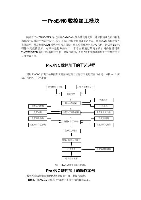
| TCW4 CANopenCANOPEN ABSOLUTE MULTI-TURN MODULAR SENSORSPECIFICATIONSFeaturesApplications• With its two-part design, the TCW4 CANopen absolute multi-turnoffers maximum flexibility for installation• Rugged and excellent resistant to shock and vibration • Robust, proven magnetic technology• Environmentally resistant, IP 67 standard (IP69K option)• Extended operating range from -30° C to 85° C• Uses universal supply 5 to 30 VDC – CAN open output• Available resolution 12 bits per turn by 16 bits of turns counting • Variety of magnet holders available• Standard PVC cable with SUBD9 connector• Factory Automation •Process AutomationTerminations PVC Cable with SUBD9 connector Macromelt PA6380,150 kgMechanicalOutput Function CANopen Minimal Cycle Time < 400µsMulti-turn 12 bits per turn and up to 16 bits of turns counting +/-0.3% on 360°Repeatability +/-0.1% on 360°Supply Voltage 5 to 30 Vdc < 1 s Current Requirements < 40mAElectricalSensata-BEI Sensors' TCW4 sensors provide absolute multi-turn measurement with a CANopen output in an over-molded, modular package that offers design flexibility and protection from the environment.Programmable ParametersCommunication ModesAll Dimensions are in millimeters.Shaft system with magnet to be ordered separately (see Accessories).DIMENSIONSResolution: Defines the resolution per revolution (0 to 4 096).Transmission Speed: Programmable from 10kBaud (1 000m) to 1 Mbaud (25 m) ; value per default : 20 Kbaud.Address: Defines the software address of the encoder on the bus (1 to 127, Value per default : id = 1).Direction: Defines the direction of count of the sensor.RAX: Defines the value of the current position (with the shaft held stationary)Sensor configuration : Reading/Writing of the sensor objects dictionary (SDO mode).3 modes are available to interrogate the encoder position/speed:CYCLIC Mode: The sensor transmits its position in an asynchronous manner. The frequency of the transmission is defined by the programmable cyclic timer register from 0 to 65 535 ms,SYNCHRO Mode:The Sensor transmits its position on a synchronous demand by the master.CONNECTIONSNOTESStray magnetic fields can interfere with accuracy and repeatability of the signal.ORDERING OPTIONS Example : TCW4_00//PBBB//12B16//BBD020(Contact the factory for special versions, ex : dimensions, connections... )ACCESSORIESKXX: Where XX is the shaft mounting diameter in mm. Standards are 06, 08, 10, 11, and 14 mm. i.e M9105/K10 mounts to a 10 mm shaft.ScrewsPage 5Sensata Technologies, Inc. (“Sensata”) data sheets are solely intended to assist designers (“Buyers”) who are developing systems that incorporate Sensata products (also referred to herein as “components”). Buyer understands and agrees that Buyer remains responsible for using its independent analysis, evaluation and judgment in designing Buyer’s systems and products. Sensata data sheets have been created using standard laboratory conditions and engineering practices. Sensata has not conducted any testing other than that specifically described in the published documentation for a particular data sheet. Sensata may make corrections, enhancements, improvements and other changes to its data sheets or components without notice.Buyers are authorized to use Sensata data sheets with the Sensata component(s) identified in each particular data sheet. HOWEVER, NO OTHER LICENSE, EXPRESS OR IMPLIED, BY ESTOPPEL OR OTHERWISE TO ANY OTHER SENSATA INTELLECTUAL PROPERTY RIGHT, AND NO LICENSE TO ANY THIRD PARTY TECHNOLOGY OR INTELLECTUAL PROPERTY RIGHT, IS GRANTED HEREIN. SENSATA DATA SHEETS ARE PROVIDED “AS IS”. SENSATA MAKES NO WARRANTIES OR REPRESENTATIONS WITH REGARD TO THE DATA SHEETS OR USEOF THE DATA SHEETS, EXPRESS, IMPLIED OR STATUTORY, INCLUDING ACCURACY OR COMPLETENESS. SENSATA DISCLAIMSANY WARRANTY OF TITLE AND ANY IMPLIED WARRANTIES OF MERCHANTABILITY, FITNESS FOR A PARTICULAR PURPOSE, QUIET ENJOYMENT, QUIET POSSESSION, AND NON-INFRINGEMENT OF ANY THIRD PARTY INTELLECTUAL PROPERTY RIGHTS WITH REGARD TO SENSATA DATA SHEETS OR USE THEREOF.All products are sold subject to Sensata’s terms and conditions of sale supplied at SENSATA ASSUMES NO LIABILITY FOR APPLICATIONS ASSISTANCE OR THE DESIGN OF BUYERS’ PRODUCTS. BUYER ACKNOWLEDGES AND AGREES THAT IT IS SOLELY RESPONSIBLE FOR COMPLIANCE WITH ALL LEGAL, REGULATORY AND SAFETY-RELATED REQUIREMENTS CONCERNING ITS PRODUCTS, AND ANY USE OF SENSATA COMPONENTS IN ITS APPLICATIONS, NOTWITHSTANDING ANY APPLICATIONS-RELATED INFORMATION CONTACT US Americas+1 (800) 350 2727**************************** EMEA**************************** +33 (3) 88 20 8080Asia Pacific*************************.com China +86 (21) 2306 1500 Japan +81 (45) 277 7117 Korea +82 (31) 601 2004 India +91 (80) 67920890Rest of Asia +886 (2) 27602006 ext 280850% of output±0.10±0.10。
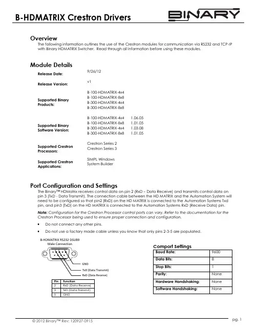
pg. 1© 2012 Binary™ Rev: 120927-0915OverviewThe following information outlines the use of the Crestron modules for communication via RS232 and TCP-IP with Binary HDMATRIX Switcher. Read through all information before using these modules.Module DetailsRelease Date: 9/26/12 Release Version:v1Supported Binary Products:B-100-HDMATRIX-4x4 B-100-HDMATRIX-8x8 B-300-HDMATRIX-4x4 B-300-HDMATRIX-8x8Supported Binary Software Version:B-100-HDMATRIX-4x4 1.06.05 B-100-HDMATRIX-8x8 1.01.05 B-300-HDMATRIX-4x4 1.03.08 B-300-HDMATRIX-8x8 1.01.05Supported Crestron Processors: Crestron Series 2 Crestron Series 3Supported Crestron Applications:SIMPL Windows System BuilderPort Configuration and SettingsThe Binary™ HDMatrix receives control data on pin 2 (RxD – Data Receive) and transmits control data on pin 3 (TxD - Data Transmit). The connection cable between the HD MATRIX and the Automation System will need to be configured so that pin2 (RxD) on the HD MATRIX is connected to the Automation Systems Txd pin, and pin3 (TxD) on the HD MATRIX is connected to the Automation Systems RxD (Receive Data) pin. Note: Configuration for the Crestron Processor control ports can vary. Refer to the documentation for the Crestron Processor being used to ensure proper connection and configuration. ∙ Do not connect any other pins.∙Do not use a factory made cable unless you know that only pins 2-3-5 are populated.TxD (Data Transmit)RxD (Data Receive)GNDB-HDMATRIX RS232 DSUB9Male ConnectionB-HDMATRIX Crestron Drivers Usage Guidepg. 2 Support: 866.838.5052System Builder SupportOnce the module is added to SystemBuilder, you will need to make all the appropriate connections to the system logic and touch panel template that you are using. 1. Drop the modules into your default User Module path.o Binary_HDMatrix(Ethernet)_v1.umc oBinary_HDMatrix(Serial)_v1.umc2. This path can be found under EDIT>PREFERENCES>USER DATABASE PATHS. Once you have placed themodules in the appropriate folder, be sure to click rebuild. 3. Next open up your project and select the Equipment view. 4. In the lower right hand corner, open the UserDatabase and drill down the By Device Type until you see SnapAV. 5. Expand the category until you see the B-100HDMATRIX. 6. Right click B-100HDMATRIX (Ethernet) or B-100HDMATRIX (Serial) and select add to system.Once you have added the object to yourprogram, you have to setup the parameters for the module.7. Right click on the object and select Properties.Then select I/O Assignment from the left hand pane. Here you should verify that the Serial or IP settings are correctly set on the I/O tab. Also, for the Ethernet version, make sure to fill out the parameter values on the properties tab. 8. Next select Audio from the left hand pane andverify that this is NOT defined as a distributed audio source.B-HDMATRIX Crestron Drivers Usage Guidepg. 3© 2012 Binary™ Rev: 120927-0915Signal and Parameter DescriptionsDIGITAL INPUTS[connect_fb>>tcp-ip_client] Connect to the output of the TCP-IP client[tcp-ip_connect] Pulse to make a TCP-IP connection to the switcher[tcp-ip_disconnect] Pulse to disconnect the TCP-IP connection from the switcher [power_on] Pulse to power on the switcher [power_off]Pulse to power off the switcher[output1-x_selection_+] Pulse to increment the input feeding output #1 [output1-x_selection_-] Pulse to decrement the input feeding output #1 [output1-x_on] Pulse to turn the #1 HDMI output on [output1-x_off] Pulse to turn the #1 HDMI output off[input_n1-8] Pulse to select this input as the “x” of your “xy” selection [output_n1-8] Pulse to select this input as the “y” of your “xy” selection [xy_take] Pulse to update the switcher with the “x” and “y” values from the above two digitals[status_poll] Pulse to have the switcher update the module with the current settings for each output[firmware_poll]Pulse to have the switcher update its firmware version as well as series and model valuesAnalog InputsMatrix_tcpip_status (Ethernet version only) Route from the TCP-IP client symbol for the matrix. Tracks connection status between the Crestron processor and the matrix[output1-8]Feed an analog value from a symbol such as an INIT to force the switcher output to a new inputSerial Inputsswitcher_rx$ Connect to the rx$ line of the com port or tcp-ip clientB-HDMATRIX Crestron Drivers Usage Guide© 2012 Binary™120927-0915Digital Outputs[client_connect>>tcp-ip_client_connect] (Ethernet version only)Tie to the connect line of the TCP-IP client[matrix_tcp-ip_logged_in] (Ethernet version only) Held high when tcp-ip client isconnected and the module has successfully logged in to the switcher[matrix_tcp-ip_not_logged_in] (Ethernet version only) Held high when the module did not successfully log in to the switcher [power_on_fb] High if the switcher is powered on [power_off_fb] High if the switcher is powered off [output1-8_on_fb] High if the output is enabled [output1-8_off_fb] High if the output is disabled[input_n1-8_fb] High when this input is selected as the “x” of your “xy” selection[output_n1-8_fb] High when this input is selected as the “y” of your “xy” selection[product_series_b100] High to indicate this product series [product_series_b300] High to indicate this product series [product_model_4x4] High to indicate a 4x4 model switcher [product_model_8x8] High to indicate a 8x8 model switcher[command_error] Pulses high for 1s when the switcher does not acknowledge the transmitted stringANALOG OUTPUTS [output1-8_feedback]Current analog value of the input assigned to this output Serial Outputsswitcher_tx$Connect to the tx$ line of the com portParameters (Ethernet Version Only)username Enter the TCP-IP login credentials in ASCII for the switcher password Enter the password in ASCII characters that for the above TPC_IP loginTcp_portThis parameter has only one valid value and is used for SystemBuilder supportContacting Technical SupportBinary HDMATRIX SupportPhone: (866) 838-5052 Email:**********************Crestron Module and Programming SupportContact Crestron for all support relating the use of these modules within Crestron programming software.。


Modular FRLs Pneumatic Mini Series G1/8 - G1/4Modular Junior Series G1/8 to G3/8Modular Maxi Series G1/4 to G3/4Modular Series G1Catalogue no. 2158IT-caMini FRLs3Mini FRLsLa linea Mini FRL è destinata all'impiego in piccoli sistemi pneumatici o in centraline di comando dove lo spazio è limitato.Il sistema permette di collegare fra loro più unitàsenza dover ricorrere a elementi terminali; in tal modo esso consente un risparmio di spazio e crea interassi di montaggio costanti,assicurando allostesso tempo un aspetto esteticamente piacevole emoderno.II singoli filtri, regolatori, lubrificatori e filtri/regolatori sono tutti realizzati con un tecnopolimero di alta qualità e sono provvisti di connessioni integrate con filettature G 1/8 o G 1/4 realizzate con insertometallico che assicura una maggior robustezza meccanica quando le unità vengono usate singolarmente.Nel complesso i singoli prodotti sono estremamente leggeri; un'unità FRL completa pesa solamente 380grammi.Il sistema Mini FRLsManopole colorate8 bar Nera 4 bar Grigia 2 barBluMini FRLs4Principali combinazioniCombinazioni Filtro/Regolatore - LubrificatoreElementi da 5 micron, regolatore da 8 bar + manometro e staffe di montaggio a pareteConnessioniSerbatoio - Scarico Serb. trasparente Serb. trasparente Serb. trasparente Scarico manuale Scarico semiautom.Scarico a impulsi G 1/8P3A-CA11BGB P3A-CA11CGB P3A-CA118GB G 1/4P3A-CA12BGBP3A-CA12CGBP3A-CA128GBOpzioni:Nota:Per i materiali v. pag 16Per le dimensioni v. pag 17P3A-CBCombinazione Filtro/Reg. + binazione FR L Combinazione FRL + Manifold dopo Regolatore Combinazione F/R L + Manifold dopo Filtro/RegolatoreG 1/412Serbatoio trasparente Scarico manuale Serbatoio trasparente Scarico semiautomatico Serbatoio trasparente Scarico automaticoB C 8Senzamanom.Conmanom.NGA B KHG 1/811Combinazioni Mini FRLElementi da 5 micron, regolatore da 8 bar + manometro e staffe di montaggio a pareteConnessioniSerbatoio - Scarico Serb. trasparente Serb. trasparente Serb. trasparente Scarico manuale Scarico semiautom.Scarico autom.G 1/8P3A-CB11BGB P3A-CB11CGB P3A-CB118GB G 1/4P3A-CB12BGBP3A-CB12CGBP3A-CB128GBXXXX X56Principali combinazioniCombinazioni di valvole di scarico rapido e di avviamento progressivo con staffe di montaggio a pareteOpzioni:Nota:Per combinazioni personalizzateconsultare l'assistenza tecnicaP3A-CSolenoidi 15 mm Distanza PIN 8 mm Connessione pilota istantaneaG QG 1/412SNota:Per i materiali v. pag 16Per le dimensioni v. pag 17Per i solenoidi v. pag. 16Le valvole diverse da quelle a 24 V DC sono da ordinarsisenza solenoide, e il solenoide è da ordinarsi separatamente.Valvola di scarico rapido e valvola di avviamento progressivoConnessioni V alvola di scar. rapido azion. a solenoide + valvola di avviam. progres. con regolaz. man.24V DCSenza Solenoide G 1/4P3A-CS12GMB2CCP3A-CS12GMBØØØValvola di scarico rapido e valvola di avviamento progressivoConnessioni V alvola di scar. rapido azion. pilotata + valvola di avviam. progres. con regolaz. man.G 1/4P3A-CS12QMBPer i solenoidi v. pag. 16MB 24V DCSenza solenoide2CC 000XX XXX X7891011121314151617Montaggi assemblatiGruppo contemente un regolatore o filtro regolatore Gruppo senza regolatore o filtro regolatore Staffe di montaggio a parete montatealle estremita di un gruppoStaffe di montaggio a parete montatealle estremita di un gruppoStaffe di montaggio a parete montateall'interno di un gruppoStaffe di montaggio a parete montateall'interno di un gruppoPneumatic1819Pneumatic20Il sistemaIl sistema Modular permette di collegare fra loro piùunità senza dover ricorrere a elementi terminali; in tal modo esso consente un risparmio di spazio e crea interassi di montaggio costanti, assicurando allo stesso tempo un aspetto esteticamente piacevole e moderno.Il sistema è costituito da unità standard con corpo principale delle stesse dimensioni, adattatori intermedi e blocchi connettori separati con diverse filettature. In questo modo il progettista dispone di un sistema veramente modulare che può essere adattato ed ampliato per soddisfare le future esigenze dell'applicazione.Il sistema permette inoltre la rimozione delle unitàdalla linea d'aria senza toccare gli attacchi fissi,semplificando quindi notevolmente la manutenzione.Il sistema Modular è costituito da filtri, filtri acoalescenza, filtri ad assorbimento, regolatori, filtri/regolatori e lubrificatori per linee d'aria, a cui si aggiunge una vasta gamma di accessori fra cui valvole di avviamento progressivo, valvole di scarico rapido, Manifold e connettori con attacco posteriore.Montaggio a pareteKit staffe angolari regolatoreFiltro/regolatoreConnettore con attacco posterioreBlocco conn.Valvola a sferaManifoldAdattatore intermedioValvola di scaricoValvola di avviamentoprogressivoLubrificatoreRegolatoreFiltroManopole colorate16 bar Arancione 8 bar Nera 4 bar Grigia 2 barBluModular Junior FRLs2122232425262728Pneumatic29303132Pneumatic33Valvole per scarico rapido ad azionamento manualeSimboloTolgono la pressione a monte e scaricano pressione a valle.Manopola a scelta rossa o nera.Connessione G1/8, G1/4, G3/8.Scarico inferiore G1/4Versione bloccabile con lucchetto.Versioni a bloccaggio manuale o a 2 posizi oni.Opzioni:Le valvole per scarico rapido sono disponibili in 2versioni, la prima è una valvola del tipo a 2 posizioni con entrambe selezionabili.La seconda versione è bloccata dall'aria compressa,questa funzione richiede il posizionamento manuale della manopola fino a quando la pressione del circuito raggiunge un valore sufficiente al blocco dellamanopola. Nel caso in cui la pressione scende sotto il valore richiesto la valvola si riposiziona scaricando ilPressione max. di ingresso 10 bar max.Temperatura da -100C a +500CPortata G 1/814.5 dm 3/s G 1/417.5 dm 3/s Peso75gDati tecniciNota:Per i materiali v . pag. 34.Silenziatore incluso in ogni prodotto343536Montaggio assemblatiGruppo contenente un regolatore o filtro regolatoreGruppo senza regolatore o filtro regolatoreStaffe a parete montate alle estremità di un gruppo Staffe a parete montate alle estremità di un gruppoStaffe di montaggio su Filtro/RegolatorePrincipale combinazione con staffe di montaggioa parete3738Il sistemaIl sistema Modular permette di collegare fra loro più unità senza dover ricorrere a elementi terminali;in tal modo esso consente un risparmio di spazio e crea interassi di montaggio costanti, assicurandoallo stesso tempo un aspetto esteticamente piacevole e moderno.Il sistema è formato da unità standard con corpoprincipale delle stesse dimensioni, adattatori intermedi e blocchi connettori separati con diverse filettature. In questo modo il progettista dispone di un sistema veramente modulare che può essere adattato ed ampliato per soddisfare le future esigenze dell'applicazione.Il sistema permette inoltre la rimozione delle unitàdalla linea d'aria senza toccare gli attacchi fissi,semplificando quindi notevolmente la manutenzione.Il sistema Modular è costituito da filtri, filtri a coalescenza, filtri ad assorbimento, regolatori,filtri/regolatori e lubrificatori per linee d'aria, a cui si aggiunge una vasta gamma di accessori fra cui valvole di avviamento progressivo, valvole discarico rapido, Manifold e connettori con attacco posteriore.Manopole colorate16 bar Arancione 8 bar Nera 4 barGrigiaKit staffe angolari regolatoreFiltro/regolatoreConnettore con attacco posterioreBlocco conn.Valvola a sferaManifoldAdattatore intermedioValvola di avviamento progressivo/di scarico rapidoLubrificatoreRegolatoreFiltroModular Maxi FRLsPneumatic39Pneumatic40Pneumatic41Pneumatic4243Pneumatic44Pneumatic454647Pneumatic484950Montaggio assemblatiGruppo contenente un regolatore o filtro regolatoreGruppo senza regolatore o filtro regolatoreStaffe a parete montate alle estremità di un gruppo Staffe a parete montate alle estremità di un gruppoStaffe di montaggio su Filtro/RegolatorePrincipale combinazione con staffe di montaggioa parete。
通道信号处理参数参数名称和说明通道信号处理参数确定 振动/压力 信号处理过程。
通过这些参数选定输出数据单位道转速信号的关系。
此外,信号处理参数影响测量值的数据单位和频谱/波形数据的范围。
针对每个通道,各有一个信号处理参数类型。
系统在通道传感器参数通道传感器参数定义了XM-120模块使用的传感器特性。
通过这些参数设置传感器的个通道,各有一个通道传感器参数配置情况。
AD 的量程。
其假设满量程时在最Guidelines for Setting t 通道信号处理参数值/注释,非常重要,一测量参数通频测量参数针对每一个通道各有一个通频测量参数类型。
通过这些参数配置测量方式和每个通频测量的滤波。
速度测量参数要:如果你没有正在使用转速计通道,应该将每转脉冲数设置为0。
使转速测量不起作用,模块提示转速计故障报警参数参数控制报警操作(警戒、危险级)、提供报警状态。
XM-120提供16种报警。
这些报警不一个通道,最多能够分配8个报警给任何一种测量。
使用这些参数配置测量和报警行为,使与报警结合起来。
120模块可定义16种报警,可以通过相同。
相同。
相同。
相同。
选中则有效清除则失效速度范围下限机械转速的下门限。
此值必须小于速度范围上限。
当转速范围开关失效时,此参数不起作用。
速度范围下限机械转速的上门限。
此值必须大于速度范围下限。
当转速范围开关失效时,此参数不起作用。
RPM (转/分钟)RPM提示:当转速范围开关有效时,必须存在转速信号(每转脉冲数设置高),并且必须提供转速信号。
转速范围开关继电器参数继电器参数控制自带继电器和继电器拓展模块继电器的操作。
通过使用这些参数来配置报应的继电器以及继电器的动作。
4-20mA输出参数4-20mA 输出参数定义这两个4-20mA 输出信号的特性。
对于每个输出,参数都是一样的。
参数名称和解释Xm configuration utility选中择有效清除则无效测量设置测量方式和4-20mA输出信号通过的通道监测数据参数参数名称和解释值/注释传感器故障可能状态值:在相关联的通道上是否存在传感器故障。
CM-OP离线编程模块说明书深圳市顾美科技有限公司V23.31版目录引言 (3)一、硬件说明 (4)1.1模块外观 (4)1.2指示灯状态及功能 (4)1.3产品优势 (5)1.4产品参数 (6)二、工作模式 (7)2.1模块与电脑通信 (7)2.2模块与PLC通讯 (11)2.3其它说明 (12)引言CM-OP离线编程模块作为有线数据传输模块,使用RS485及RS232通讯方式,使模块与PLC通讯直接进行程序上传下载工作。
特别是针对产线上的自动化设备,使程序下载工作变得轻而易举。
使工程师远离产线噪音,改善工作环境的同时又大大提高了工作效率。
功能齐全的同时操作简单易学,产线工人也可轻松掌握使用方法。
一、硬件说明1.1模块外观1.2指示灯状态及功能指示灯名称指示功能状态WORK 模块与PLC 通讯指示未通讯时常亮;通讯成功时约每秒闪烁1次;上传或下载数据时快闪;TXD 发送数据指示灯U 状态时,此灯闪烁D 状态时,此灯快闪RXD 接收数据指示灯U 状态时,此灯快闪D 状态时,此灯闪烁PWR 电源指示上电此灯常亮CHG充电指示USB 充电时闪烁1.3产品优势1、减少设备的停机时间,当对下一个任务进行编程时,之前的设备程序可以仍在生产线上工作;2、对于生产线上的自动化设备,使用模块对PLC下载程序,可使编程者远离繁重的搬运工作,改善了编程环境;3、离线编程使用范围广泛,可以对FX2N系列、FX3G系列等PLC进行程序编程;4、用户使用方便,适应性强,能方便地实现优化编程;5、便于更改PLC程序,提高工作效率;6、无须参数设置,即插即用;7、内置可充电电池,单次充电可不间断使用5小时以上;1.4产品参数产品类型CM-OP 离线编程模块产品图片正面侧面安装方式35MM 标准导轨安装、手持设备连接方式MICRO USB &RS485/RS232通讯协议三菱编程口协议电源电压内置2000mAH 可充电锂电池充电电压5V 最大输入电流50mA 静态功耗<0.5W 净重50g 外型尺寸90mm*60mm*32mm 工作环境温度-20℃~85℃编程软件兼容三菱PLC 编程软件GX8.52/GX8.86和WORKS 2相关手册下载:二、工作模式2.1模块与电脑通信1、模块与电脑通过USB进行连接,连接方法如下图所示:此时电脑的设备管理器中会出现一个对应的串口(电脑需要安装USB转串口驱动,驱动可至顾美官网:配套软件下载---《USB转485驱动》下载),如COM5:2、给模块上电(USB接通或者打开电源开关)。

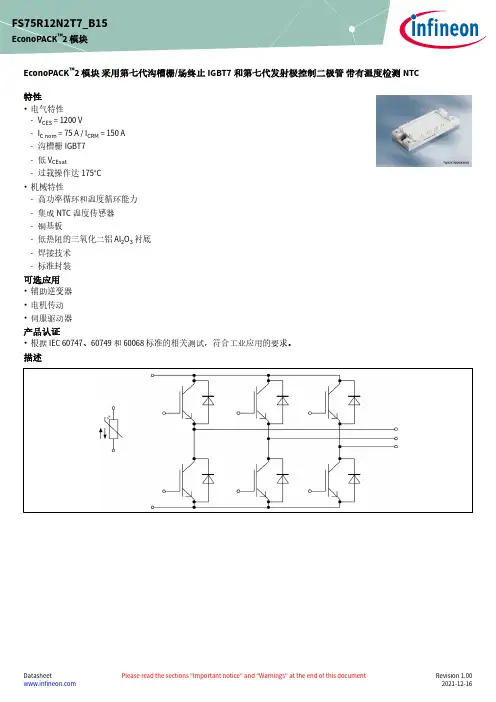
EconoPACK ™2 模块 采用第七代沟槽栅/场终止IGBT7和第七代发射极控制二极管带有温度检测NTC 特性•电气特性-V CES = 1200 V-I C nom = 75 A / I CRM = 150 A -沟槽栅IGBT7-低 V CEsat-过载操作达175°C•机械特性-高功率循环和温度循环能力-集成NTC 温度传感器-铜基板-低热阻的三氧化二铝 Al 2O 3 衬底-焊接技术-标准封装可选应用•辅助逆变器•电机传动•伺服驱动器产品认证•根据 IEC 60747、60749 和 60068 标准的相关测试,符合工业应用的要求。
描述FS75R12N2T7_B15EconoPACK ™2 模块内容描述 . . . . . . . . . . . . . . . . . . . . . . . . . . . . . . . . . . . . . . . . . . . . . . . . . . . . . . . . . . . . . . . . . . . . . . . . . . . . . . . . . . . . . . . . .1特性 . . . . . . . . . . . . . . . . . . . . . . . . . . . . . . . . . . . . . . . . . . . . . . . . . . . . . . . . . . . . . . . . . . . . . . . . . . . . . . . . . . . . . . . . .1可选应用 . . . . . . . . . . . . . . . . . . . . . . . . . . . . . . . . . . . . . . . . . . . . . . . . . . . . . . . . . . . . . . . . . . . . . . . . . . . . . . . . . . . .1产品认证 . . . . . . . . . . . . . . . . . . . . . . . . . . . . . . . . . . . . . . . . . . . . . . . . . . . . . . . . . . . . . . . . . . . . . . . . . . . . . . . . . . . .1内容 . . . . . . . . . . . . . . . . . . . . . . . . . . . . . . . . . . . . . . . . . . . . . . . . . . . . . . . . . . . . . . . . . . . . . . . . . . . . . . . . . . . . . . . . .2 1封装 . . . . . . . . . . . . . . . . . . . . . . . . . . . . . . . . . . . . . . . . . . . . . . . . . . . . . . . . . . . . . . . . . . . . . . . . . . . . . . . . . . . . . . . . .3 2IGBT, 逆变器 . . . . . . . . . . . . . . . . . . . . . . . . . . . . . . . . . . . . . . . . . . . . . . . . . . . . . . . . . . . . . . . . . . . . . . . . . . . . . . . . .3 3二极管,逆变器 . . . . . . . . . . . . . . . . . . . . . . . . . . . . . . . . . . . . . . . . . . . . . . . . . . . . . . . . . . . . . . . . . . . . . . . . . . . . . . .5 4负温度系数热敏电阻 . . . . . . . . . . . . . . . . . . . . . . . . . . . . . . . . . . . . . . . . . . . . . . . . . . . . . . . . . . . . . . . . . . . . . . . . .6 5特征参数图表 . . . . . . . . . . . . . . . . . . . . . . . . . . . . . . . . . . . . . . . . . . . . . . . . . . . . . . . . . . . . . . . . . . . . . . . . . . . . . . . .7 6电路拓扑图 . . . . . . . . . . . . . . . . . . . . . . . . . . . . . . . . . . . . . . . . . . . . . . . . . . . . . . . . . . . . . . . . . . . . . . . . . . . . . . . . .12 7封装尺寸 . . . . . . . . . . . . . . . . . . . . . . . . . . . . . . . . . . . . . . . . . . . . . . . . . . . . . . . . . . . . . . . . . . . . . . . . . . . . . . . . . . .13 8模块标签代码 . . . . . . . . . . . . . . . . . . . . . . . . . . . . . . . . . . . . . . . . . . . . . . . . . . . . . . . . . . . . . . . . . . . . . . . . . . . . . . .14修订历史 . . . . . . . . . . . . . . . . . . . . . . . . . . . . . . . . . . . . . . . . . . . . . . . . . . . . . . . . . . . . . . . . . . . . . . . . . . . . . . . . . . .15免责声明 . . . . . . . . . . . . . . . . . . . . . . . . . . . . . . . . . . . . . . . . . . . . . . . . . . . . . . . . . . . . . . . . . . . . . . . . . . . . . . . . . . .161封装表 1绝缘参数特征参数代号标注或测试条件数值单位绝缘测试电压V ISOL RMS, f = 50 Hz, t = 1 min 2.5kV 模块基板材料Cu内部绝缘基本绝缘 (class 1, IEC 61140)Al2O3爬电距离d Creep端子至散热器10.0mm 电气间隙d Clear端子至散热器7.5mm 相对电痕指数CTI>200相对温度指数 (电)RTI封装140°C 表 2特征值特征参数代号标注或测试条件数值单位最小值典型值最大值杂散电感,模块L sCE17nH 模块引线电阻,端子-芯片R CC'+EE'T C=25°C, 每个开关 3.3mΩ储存温度T stg-40125°C 模块安装的安装扭距M根据相应的应用手册进行安装M5, 螺丝36Nm 重量G180g 注:The current under continuous operation is limited to 50A rms per connector pin.2IGBT, 逆变器表 3最大标定值特征参数代号标注或测试条件数值单位集电极-发射极电压V CES T vj = 25 °C1200V 连续集电极直流电流I CDC T vj max = 175 °C T C = 100 °C75A 集电极重复峰值电流I CRM t P = 1 ms150A 栅极-发射极峰值电压V GES±20V表 4特征值特征参数代号标注或测试条件数值单位最小值典型值最大值集电极-发射极饱和电压V CE sat I C = 75 A, V GE = 15 V T vj = 25 °C 1.55 1.80VT vj = 125 °C 1.69T vj = 175 °C 1.77栅极阈值电压V GEth I C = 1.28 mA, V CE = V GE, T vj = 25 °C 5.15 5.80 6.45V 栅极电荷Q G V GE = ±15 V, V CE = 600 V 1.25µC 内部栅极电阻R Gint T vj = 25 °C2Ω输入电容C ies f = 100 kHz, T vj = 25 °C, V CE = 25 V, V GE = 0 V15.1nF 反向传输电容C res f = 100 kHz, T vj = 25 °C, V CE = 25 V, V GE = 0 V0.053nF 集电极-发射极截止电流I CES V CE = 1200 V, V GE = 0 V T vj = 25 °C0.014mA 栅极-发射极漏电流I GES V CE = 0 V, V GE = 20 V, T vj = 25 °C100nA开通延迟时间(感性负载)t don I C = 75 A, V CE = 600 V,V GE = ±15 V, R Gon = 5.6 ΩT vj = 25 °C0.164µs T vj = 125 °C0.178T vj = 175 °C0.185上升时间(感性负载)t r I C = 75 A, V CE = 600 V,V GE = ±15 V, R Gon = 5.6 ΩT vj = 25 °C0.048µs T vj = 125 °C0.053T vj = 175 °C0.057关断延迟时间(感性负载)t doff I C = 75 A, V CE = 600 V,V GE = ±15 V, R Goff = 5.6 ΩT vj = 25 °C0.300µs T vj = 125 °C0.380T vj = 175 °C0.420下降时间(感性负载)t f I C = 75 A, V CE = 600 V,V GE = ±15 V, R Goff = 5.6 ΩT vj = 25 °C0.120µs T vj = 125 °C0.200T vj = 175 °C0.270开通损耗能量 (每脉冲)E on I C = 75 A, V CE = 600 V,Lσ = 35 nH, V GE = ±15 V,R Gon = 5.6 Ω, di/dt =1200 A/µs (T vj = 175 °C)T vj = 25 °C7.96mJ T vj = 125 °C10.8T vj = 175 °C12.3关断损耗能量 (每脉冲)E off I C = 75 A, V CE = 600 V,Lσ = 35 nH, V GE = ±15 V,R Goff = 5.6 Ω, dv/dt =3200 V/µs (T vj = 175 °C)T vj = 25 °C 5.02mJ T vj = 125 °C7.68T vj = 175 °C9.46(待续)表 4(续) 特征值特征参数代号标注或测试条件数值单位最小值典型值最大值短路数据I SC V GE≤ 15 V, V CC = 800 V,V CEmax=V CES-L sCE*di/dt t P≤ 8 µs,T vj=150 °C260At P≤ 7 µs,T vj=175 °C250结-外壳热阻R thJC每个 IGBT0.475K/W 外壳-散热器热阻R thCH每个 IGBT, λgrease= 1 W/(m*K)0.141K/W 允许开关的温度范围T vj op-40175°C注:T vj op > 150°C is allowed for operation at overload conditions. For detailed specifications, please refer to AN2018-14.3二极管,逆变器表 5最大标定值特征参数代号标注或测试条件数值单位反向重复峰值电压V RRM T vj = 25 °C1200V 连续正向直流电流I F75A 正向重复峰值电流I FRM t P = 1 ms150A I2t-值I2t t P = 10 ms, V R = 0 V T vj = 125 °C1150A²sT vj = 175 °C740表 6特征值特征参数代号标注或测试条件数值单位最小值典型值最大值正向电压V F I F = 75 A, V GE = 0 V T vj = 25 °C 1.72 2.10VT vj = 125 °C 1.59T vj = 175 °C 1.52反向恢复峰值电流I RM V R = 600 V, I F = 75 A,V GE = -15 V, -di F/dt =1200 A/µs (T vj = 175 °C)T vj = 25 °C43A T vj = 125 °C56T vj = 175 °C65(待续)表 6(续) 特征值特征参数代号标注或测试条件数值单位最小值典型值最大值恢复电荷Q r V R = 600 V, I F = 75 A,V GE = -15 V, -di F/dt =1200 A/µs (T vj = 175 °C)T vj = 25 °C 4.94µC T vj = 125 °C10.2T vj = 175 °C13.7反向恢复损耗(每脉冲)E rec V R = 600 V, I F = 75 A,V GE = -15 V, -di F/dt =1200 A/µs (T vj = 175 °C)T vj = 25 °C 1.45mJ T vj = 125 °C 3.32T vj = 175 °C 4.62结-外壳热阻R thJC每个二极管0.708K/W 外壳-散热器热阻R thCH每个二极管, λgrease= 1 W/(m*K)0.153K/W 允许开关的温度范围T vj op-40175°C注:T vj op > 150°C is allowed for operation at overload conditions. For detailed specifications, please refer to AN2018-14.4负温度系数热敏电阻表 7特征值特征参数代号标注或测试条件数值单位最小值典型值最大值额定电阻值R25T NTC = 25 °C5kΩR100偏差ΔR/R T NTC = 100 °C, R100 = 493 Ω-55%耗散功率P25T NTC = 25 °C20mW B-值B25/50R2 = R25 exp[B25/50(1/T2-1/(298,15 K))]3375K B-值B25/80R2 = R25 exp[B25/80(1/T2-1/(298,15 K))]3411K B-值B25/100R2 = R25 exp[B25/100(1/T2-1/(298,15 K))]3433K 注:根据应用手册标定4 负温度系数热敏电阻6电路拓扑图图 17封装尺寸图 28 模块标签代码8模块标签代码图 3修订历史修订历史修订版本发布日期变更说明1.002021-12-16Final datasheet商标所有参照产品或服务名称和商标均为其各自所有者的财产。

techrom 说明书产品型号:TCS-20所属分类:粘度计产品时间:2021-03-26简要描述:日本techrom用于热脱附装置的管调节器TCS-20 使用热解吸装置(热分解)时,调节收集管(吸附管)的工作是最基本的工作。
TCS-20是专yong设备,可同时调节(燃烧)多达20个加热和解吸设备中使用的收集管。
更轻松,更有效地调节收集管使用热解吸装置(热分解)时,调节收集管(吸附管)的工作是最基本的工作。
TCS-20是专yong设备,可同时调节(燃烧)多达20个加热和解吸设备中使用的收集管。
z理想的多级温升可减少填料损坏。
卧式实现了热量分布小的加热炉,并实现了理想的调节。
除了通过升温程序进行调节外,还可以通过采用冷却风扇在短时间内冷却加热炉(烤箱)。
免工具管安装是带O型圈的一键式安装。
如果将压力调节为0.1MPa,则所有管中的流速相同。
(约45㎖/分钟)根据应用定制由于它是可移动的容器,因此可以替换为各种规格。
除了容器之外,您还可以选择加热炉(长,短)和冷却风扇(标准,静音型),因此可以根据您的应用进行自定义。
日本techrom用于热脱附装置的管调节器TCS-20主要规格散热功能:是的(370℃→50℃约20分钟)加热温度:室温+50-370℃流量设定范围:0-100毫升/分钟电源:AC100V 5A使用的气体:N2推荐纯度99.999%以上能量消耗;450瓦容器;1/4管容器(用于20件)x 1或6 mm管容器(用于20件)x 1 1/4管容器(用于10个)6毫米管容器(用于20个)选项:6mm管容器(用于10个)组合容器(用于1/4 10件6mm 10件)合并容器(自定义)*组合容器(自定义)可根据客户要求进行更改。
(最多20个)。
T ecnomatix ®软件套件是一套完善的数字化制造解决方案,可以帮助公司快速确立提升效率、降低成本的最佳战略。
/plm制造运营活动决定着公司能否赢利和发展。
无论公司开发创新产品的效率有多高,除非能让生产设施发挥最大的功效,否则仍然无法实现业务目标并赢得竞争优势。
上自董事会,下至车间,世界顶级制造商都在致力于整个产品生命周期价值链的资本运作,力争赢得竞争优势,他们采取的方式有:提升流程创新在整个企业的可见性同步利用工程设计资产与制造交付成果,加快上市速度发挥经过实践检验的生产灵活性,抓住投资于新兴市场的机会通过不断优化制造资源和基本建设投资推动可持续赢利降低成本,减少潜在的违规风险领先的制造商会在产品生命周期中充分利用数字化制造,因为他们知道,创新性产品设计的商业成功取决于制造运营活动的表现。
来自Siemens PLM Software 的数字化制造解决方案革新PLM战略在当今的全球市场中,机会几乎无处不在,但盲目扩张不一定是能够抓住这些机会的有效投资手段。
富于创新的制造商正在寻求一些更为高效的方法来管理日益复杂的价值链,以便推动可持续赢利。
意识到需要更快的速度、更广的控制范围以及更深刻的洞察力,领先的制造商越来越多地借助于Siemens PLM Software推出的数字化制造解决方案。
T ecnomatix通过将所有制造专业领域与产品工程设计联系起来实现创新,其中包括:流程布局和设计、流程模拟/工程以及生产管理。
T ecnomatix的全方位数字化制造解决方案组合构建于T eamcenter软件的基础之上,具有企业级的可扩展灵活性,致力于实现市场上唯一完全并行的工程设计环境。
利用开放式体系架构,Siemens通过开放式整合提供世界一流的解决方案,从而缩短交付时限,提高制造规划工作的准确性。
通过将产品、流程、资源和工厂数据紧密联系在一起,制造商可拥有在数字化制造领域被公认为领先的全套流程导向型技术。
X20(c)AT64021 General informationThe module is equipped with 6 inputs for J, K, N, S, B and R thermocouple sensors. The module has an integrated terminal temperature compensation.•6 inputs for thermocouples•For sensor types J, K, N, S, B, R•Additional direct raw value measurement•Integrated terminal temperature compensation•Configurable filter time2 Coated modulesCoated modules are X20 modules with a protective coating for the electronics component. This coating protects X20c modules from condensation and corrosive gases.The modules' electronics are fully compatible with the corresponding X20 modules.For simplification purposes, only images and module IDs of uncoated modules are used in this data sheet.The coating has been certified according to the following standards:•Condensation: BMW GS 95011-4, 2x 1 cycle•Corrosive gas: EN 60068-2-60, Method 4, Exposure 21 days3 Order dataTable 1: X20AT6402, X20cAT6402 - Order data4 Technical dataTable 2: X20AT6402, X20cAT6402 - Technical dataTable 2: X20AT6402, X20cAT6402 - Technical data 1)Ta min.: 0°CTa max.: See environmental conditions2)Based on the entire measurement range without consideration of the cold junction measurement error3)Based on the current measured value.4)Based on the entire measurement range.5 LED status indicatorsFor a description of the various operating modes, see the section "re LEDs" in chapter 2 "System characteristics"of the X20 system user's manual.6 Pinout1X 20 A T 640223456r e 7 Connection exampleAT8 Input circuit diagram9 Ceramic heating element with integrated thermo elementsWe recommend connecting the minus input of the thermo element to the minus input of the supply feed module. This prevents potential measurement errors caused by ripple voltage effects in the measurement signal.10 External cold junctionGeneral informationAn external cold junction temperature value can be predefined for the module for measurement value correction. This makes it possible to set up an external cold junction. The same external cold junction temperature is used for measurement value correction on all channels.An external cold junction makes sense in the following applications and situations:•Large distances between the controller and measurement point•To increase precisionTo bridge large distancesSetting up an external cold junction is recommended when there are large distances between the controller and the measurement point. The thermocouple voltage is routed from the external cold junction to the terminal on the X20AT6402 via copper wires. The temperature measured at the external cold junction (e.g. with PT100 -X20AT4222) is stored in the I/O area of the X20AT6402 module. The X20AT6402 uses the measured voltage andthe cold junction temperature to internally calculate the needed thermocouple temperature.Increased precisionSetting up an external cold junction is recommended to increase precision. The external cold junction is set up asdescribed above. The installation of an external cold junction is especially helpful in the following cases:•A module consuming more power than 1 W is connected in addition to the X20AT6402.•No modules but the X20AT6402 are connected•With strongly fluctuating ambient conditions (draft, temperature)11 Register description11.1 General data pointsIn addition to the registers listed in the register description, the module also has other more general data points. These registers are not specific to the module but contain general information such as serial number and hardware version.These general data points are listed in the "General data points" section of chapter 4 "X20 system modules" in the X20 system user's manual.11.2 Function model 0 - default11.3 Function model 1 - External cold junction temperature11.4 Function model 254 - Bus controller1)The offset specifies the position of the register within the CAN object.11.5 General information11.5.1 Raw value measurementIf a sensor type other than J, K, N, S, B or R is used, the terminal temperature must be measured on at least one input. Based on this value, the user must then implement terminal temperature compensation.11.5.2 TimingThe timing for acquiring measurement values is determined by the converter hardware. All enabled inputs are converted during each conversion cycle. In addition, the terminal temperature is measured (not in function model 1). Any inputs that are not needed can be switched off, which reduces the I/O update time. Inputs can also be only switched off temporarily. Measuring the terminal temperature is switched off in function model 1.11.5.3 Conversion timeThe conversion time depends on the number of channels and the function model. For the formulas listed in the table, "n" corresponds to the number of channels that are switched on.ExamplesInputs are filtered using a 50 Hz filter.11.6 Configuration11.6.1 Input filter and ambient conditionsName:ConfigOutput01This register configures input filters and ambient conditions.Input filterThe filter time for all analog inputs is defined using the input filter parameter.Environmental conditionsAmbient conditions are set in order to adjust the internal terminal temperature characteristic curve to the type and amount of generated heat dissipated to the module.This selection is based on the power consumption of the modules connected immediately to the left and right on the X2X Link. Power consumption values can also be found in the technical data for the corresponding module. The higher value is used for the configuration.Bit structure:11.6.2 Sensor typeName:ConfigOutput02This module is designed for a wide range of sensor types. The sensor type must be configured because of the different alignment values.11.6.3 Channel disablingName:ConfigOutput03By default, all channels are switched on. To save time, individual channels can be switched off (see "Conversion time" on page 8).Bit structure:X20(c)AT6402 11.7 Communication11.7.1 Analog inputsName:Temperature01 to Temperature06Analog input value depending on the configured sensor type:In order for the user to always be supplied with a defined output value, the following must be taken into consid-eration:•Up to the first conversion, 0x8000 is output.•After switching the sensor type, 0x8000 is output until the first conversion.•If the input is not switched on, 0x8000 is output.11.7.2 I/O cycle counterName:IOCycleCounterThe cyclic counter increases after all input data has been updated.11.7.3 Input statusThe module's inputs are monitored. A change in the monitoring status generates an error message.In addition to the status info, the error type also sets the analog value as follows:11.7.3.1 Status of inputs 1 to 4Name:StatusInput01Bit structure:X20(c)AT640211.7.3.2 Status of inputs 5 to 6Name:StatusInput02Bit structure:11.7.4 Reads the internal cold junction temperatureName:CompensationTemperatureThe internal cold junction temperature is stored in this register.11.7.5 Defines the external cold junction temperatureName:ExternalCompensationTemperatureThe external cold junction temperature is defined in this register.11.8 Minimum cycle timeThe minimum cycle time defines how far the bus cycle can be reduced without communication errors occurring. It should be noted that very fast cycles decrease the idle time available for handling monitoring, diagnostics and acyclic commands.11.9 Minimum I/O update timeThe minimum I/O update time defines how far the bus cycle can be reduced while still allowing an I/O update to take place in each cycle.For the formulas listed in the table, 'n' corresponds to the number of channels that are switched on.。
小型版温控模块数据手册产品综述●TCM系列温控模块,可用于驱动半导体制冷片TEC或者电阻发热式元件(比如陶瓷加热片/棒、PTC加热片)。
●支持NTC热敏电阻;<0.002℃分辨率;传感器开路保护。
●±0.002℃的稳定性;PID系数可调节;PID系数自动整定功能。
●致冷、加热和双向三种输出模式可选。
●直流电压源输出,纹波小,延长半导体制冷片的寿命,提高制冷效率,提高稳定性。
●过压、过温保护,可选的故障后自动恢复功能。
●可独立运行,也可用手持用户接口模块或计算机进行实时控制、记录数据和实时曲线。
●支持1个串口控制多个温控模块。
●高性能:精心设计的测温和控制系统,实现高分辨率、高稳定性。
●自动整定功能:易使用的自动整定功能,简化PID系数设置难度;自动整定完成后会生成优化的PID系数,获得速度快、过冲小、振荡少的温控性能。
●开放式平台:提供完整串口控制命令,用户可自己编程通过计算机或单片机控制温控模块;免费提供上位机软件,可实现参数观测、设置、数据记录和曲线显示等功能。
●强大灵活性:各种参数都可以在用户软件中调节、设置、保存,方便用户在不同的温控系统中使用该温控模块。
1.传感器参数可灵活设置,支持不同规格参数的热敏电阻。
2.输出模式、最大输出电压等输出参数可灵活设置,可适应不同型号TEC需求。
3.各种保护的阈值可软件灵活设置。
1. 计算机:可计算机控制,附送的连接线可连接模块至计算机的RS232串口;如计算机没串口,可使用USB转DB9公口串口线;上位机软件免费,中文界面,功能丰富,操作简单。
2. 显示模块UIMx:如果不方便使用计算机控制,可以使用显示模块UIMx(需要另外选购)实现参数显示设置。
有三种可选:可自定义数码管显示模块UIME,通用显示模块UIM,可自定义彩屏显示模块UIMP。
3. 单片机:可使用单片机的串口(需转换为RS232电平)与模块的串口通讯,并控制模块。
4. 独立运行:除了与用户交互的功能外,模块的所有核心功能都在模块自身上;因此,参数设置保存后,模块可以独立运行,不需要一直连接UIM、计算机。
ZH-T08NTC8通道热电阻测温模块使用说明书(V3.5)一、概述本模块采用高精度32位AD芯片+ARM32位工业级MCU,精度高,抗干扰好。
可精确测量0.02Ω至10MΩ阻值间的各种热电阻阻值,并计算出温度,可广泛用于各种热电阻测温以及热电阻阻值校正场合。
具有以下特点:✧具有宽电源供电9-30V。
✧32位高精度AD,阻值分辨率达1mΩ,精度最高达千分之一;温度分辨率0.1℃,精度达±0.1℃。
✧内部兼容PT100、PT1000、Cu50、Cu100、NTC(10k B=3435)、NTC(10k B=3950)、NTC(100k B=3950)等温度探头的温度测量。
✧出厂默认2线制测量,如果被测热电阻引线较长,可以采用3线制测量,精度更高;✧采样周期具有四种速率可设置。
✧多个被测电阻有一端短路时,不影响测试效果。
✧采集输入、电源、通讯三种相互隔离,可靠性高。
✧可以用RS485或以太网做为通信接口;当采用以太网版本(插座会占用第7与第8通道位置,所以此版本只有6通道)时,可同时使用RS485接口,使模块同时拥有两个通讯口,可用于冗余高可靠场合;✧可灵活自选Modbus-RTU或Modbus-TCP工业通信协议,与各种组态屏、工控软件以及模组进行可靠通信。
二、产品主型号ZH-T08NTC-14N18通道温度,RS485接口;ZH-T06NTC-34N16通道温度,以太网接口+RS485接口;三、性能指标温度测量范围与精度0x0200~0x0207寄存器值热电阻类型测温范围测量误差第1档更新速率第2档更新速率第3档与第4档速率9PT100-200℃~800℃±0.1℃±0.4℃±2℃10PT1000-200℃~800℃±0.1℃±0.2℃±2℃11NTC10k B=3435-30℃~100℃±0.1℃±0.1℃±0.2℃14Cu50-50℃~150℃±0.1℃±0.5℃±2℃15Cu100-50℃~150℃±0.1℃±0.3℃±2℃16NTC100k B=3950-30℃~300℃±0.1℃±0.1℃±0.5℃17NTC10k B=3950-40℃~300℃±0.1℃±0.4℃±2℃此测量误差用标准电阻对照热电阻标称阻值表校对,实际热电阻阻值与标称值可能有误差,有可能会超过此表误差;用户可以通过修改0x2C0~0x02C7来修正温度误差,这样精度可以达到更高;以上数据为采用2线制时所测得的精度,如果被测电阻引线较长,可以采用3线制,可以避免因引线线阻引起的误差。
温湿度模块DHT11芯片根据芯片时序图,可以看出这个芯片涉及到微秒的操作,所以利用了M0系统自带的晶振时钟,相当精确,再根据时序可以读到数据,芯片里的DATA用于微处理器与DHT11之间的通讯和同步,采用单总线数据格式,一次传送40位数据,高位先出。
数据格式:8bit湿度整数数据 + 8bit湿度小数数据+8bit温度整数数据 + 8bit温度小数数据+8bit校验位。
◎校验位数据定义“8bit湿度整数数据 + 8bit湿度小数数据+8bit温度整数数据 + 8bit温度小数数据”8bi t 校验位等于所得结果的末8位。
数据时序图步骤一:DHT11上电后(DHT11上电后要等待 1S 以越过不稳定状态在此期间不能发送任何指令),测试环境温湿度数据,幵记录数据,同时 DHT11的DATA数据线由上拉电阻拉高一直保持高电平;此时 DHT11的 DATA 引脚处于输入状态,时刻检测外部信号。
步骤二:微处理器的I/O设置为输出同时输出低电平,且低电平保持时间不能小于18ms,然后微处理器的I/O设置为输入状态,由于上拉电阻,微处理器的I/O即DHT11的DATA数据线也随之变高,等待DHT11作出回答信号,发送信号如图所示:程序如下:(不必纠结管脚问题,不同的版本管脚不同)GPIOSetDir(PORT3, 2, 1); // Set PIO1_5 to outputGPIOSetValue(PORT3, 2, 0);delay_ms(30);GPIOSetValue(PORT3, 2, 1);GPIOSetDir(PORT3, 2, 0);首先设置为高电平输出,然后延时30毫秒,再将该端口设置为输入。
步骤三:DHT11的DATA引脚检测到外部信号有低电平时,等待外部信号低电平结束,延迟后DHT11的DATA引脚处于输出状态,输出 80微秒的低电平作为应答信号,紧接着输出 80 微秒的高电平通知外设准备接收数据,微处理器的 I/O 此时处于输入状态,检测到 I/O 有低电平(DHT11回应信号)后,等待80微秒的高电平后的数据接收,发送信号如图所示:此时程序中需要延时微秒数量级所以采用了cortex-M0系列系统自带的晶振时钟:延时:GPIOSetInterrupt(PORT3, 2, 0, 0, 0);GPIOIntEnable(PORT3, 2);for(i=0; i<3; i++){GPIOSetInterrupt(PORT3, 2, 0, 0, i&0x01);while(p3_2_counter == cnt_last);cnt_last = p3_2_counter;}上面这段程序的意思是:先判断是否是下降沿,当i=0,下降沿触发,继续执行,如果没有来下降沿的话,那么p3_2_counter == cnt_last就永远是真,一直在这里阻塞,当下降沿来了,则触发了PIO3_2中断,这个中断的处理如下:if(GPIOIntStatus(PORT3, 2)){p3_2_tc = SysTick->VAL; //将 p3_2_tc赋值为计数器当前的剩余次数。
8-Channel Thermocouple Input Ethernet Data Acquisition ModuleOM-NET-TCU E ight 24-Bit DifferentialThermocouple Inputswith ThermocoupleChannel-to-Host IsolationU4 Samples/Sec ChannelMaximum Sample RateU T wo Integrated ColdJunction Compensation(CJC) SensorsU O pen ThermocoupleDetectionU8 Digital I/O IsolatedFrom ThermocoupleInputs and HostU D igital Outputs Have±24 mA Drive Capabilityand are Configurable asThermocouple AlarmsU10/100 Ethernet InterfaceThe OM-NET-TC thermocouple input data acquisition moduleoffers high-accuracy temperature measurement with an Ethernet interface. The device offers thebest value per channel and thebest possible accuracy becausethe accuracy of the internal measurement electronics exceeds the accuracy specifications ofthe thermocouple sensors. TheOM-NET-TC is functionally equivalent to an OMEGA TM OM-USB-TC module (USB interface to computer) which makes application migration very easy.Ethernet InterfaceThe OM-NET-TC has a built-in high-speed communication port. Users can remotely access and configure the device with software over the Internet.Thermocouple Input Connect up to eight differential thermocouple (TC) input channelsto the OM-NET-TC. The OM-NET-TC supports a maximum sample rate of 4 S/s per channel, and thermocouple types J, K, T, E, R, S, B and N. Thermocouple types are software-selectable per channel. Cold-JunctionCompensationThe OM-NET-TC has twohigh-resolution cold-junctioncompensation (CJC) sensors (oneper four thermocouple inputs).Open-ThermocoupleDetectionThe OM-NET-TC is equipped withopen-thermocouple detection(OTD) for all thermocouple inputchannels. With OTD enabled,users can monitor for broken ordisconnected thermocouple inputs.Digital I/OThe OM-NET-TC has eight digitalI/O channels that are electricallyisolated from the analog circuits.Each bit is individually configurablefor input or output. Data can betransferred at rates up to 5 kS/swhen the device and host areconnected by Ethernet to the samelocal network. Typical throughputis system-dependent. All DIOchannels are pulled high by defaultto 5V through 47 kΩ resistors witha jumper on the circuit board. Eachjumper configures the digital portfor pull-up or pull-down.Temperature AlarmsEach digital output can beoptionally configured as an alarmfor each thermocouple input.When an alarm is enabled, theoutput line associated with thealarm is driven to the appropriatestate determined by the alarmoptions and input temperature.Use the alarm outputs to control adevice or application that indicateswhen a temperature threshold hasbeen exceeded, or to indicate anopen thermocouple condition.Counter InputThe 32-bit event counter pincounts TTL pulses, and acceptsfrequency inputs up to 10 MHz.PowerThe OM-NET-TC requires externalpower from the 5V, 1A poweradapter (OM-NET-PS) includedwith the device.CalibrationThe OM-NET-TC is factory-calibrated using a NIST-traceablecalibration process. Specificationsare guaranteed for one year.For calibration beyond one year,Contact Omega and return thedevice for recalibration.OM-NET-TC shownsmaller than actual size.TracerDAQ Pro Strip Chartwith Measurements.TracerDAQ Strip Chart.Features ComparisonSoftwareThe OMB-NET -TC module ships with an impressive array of software, including the new TracerDAQ ®, a full-featured, out-of-the-box data logging, viewing, and analysis application. Driver support and detailed example programs are included for Universal Library programming libraries for Microsoft ® Visual Studio ® programminglanguages, and other languages, including DASYLab ®, and ULx for NI LabVIEW ® (comprehensive library of VIs and example programs compatible with 32-bit and 64-bit LabVIEW 2010 or later) and InstaCal TM installation, calibration and test utility-powerful solutions for programmers and nonprogrammers alike. These modules operate under Microsoft Windows ® VISTA/7/8/10 (32-bit and 64-bit) operating systems.The OMB-NET -TC data acquisition module is supplied with TracerDAQ software which is a collection of four virtual instrument applicationsused to graphically display and store input data and generate output signals:• S trip Chart—Log and graph values acquire from analoginputs, digital inputs, temperature inputs and counter inputs • O scilloscope—Display values acquired from analog inputs • F unction Generator—Generate waveforms for analog outputs• R ate Generator—Generate waveforms for counter outputs TracerDAQ PRO is an enhanced version of TracerDAQ and isavailable as a purchased upgrade (SWD-TRACERDAQ-PRO). A comparison of some of thefeatures included in TracerDAQ vs TracerDAQ Pro is shown below.Specifications(Typical for 25°C unlessotherwise specified) THERMOCOUPLE INPUTA/D Converter Type: Delta-SigmaA/D Resolution: 24-bitNumber of Channels: 8 differential channelsIsolation Between Any Thermocouple Input Channel and Digital/Chassis Differential Input Impedance: 40 MΩInput Current:O pen Thermocouple DetectDisabled: 1 nAO pen Thermocouple DetectEnabled: 65 nACommon Mode Rejection(f in = 50 Hz or 60 Hz): 110 dBNoise Rejection(f in = 50 Hz or 60 Hz): 75 dBSample Rate: 4 Hz max (per channel).The enabled thermocouple inputs arecontinuously converted at the maximumA/D converter rate. If channels areenabled and have an open thermocoupleconnection the sampling rate will be lower.. For best results, it is recommended to use electrically insulated thermocouples when possible.Measurement Sensitivity (SmallestChange in Temperature That Can Be Detected):Thermocouple Type J,K,T,E,N: 0.09°C Thermocouple Type R,S: 0.11°C Thermocouple Type B: 0.13°CWarm-Up Time: 20 minutes minOpen Thermocouple Detect Response Time: 1 sCJC Sensor Accuracy (0 to 45°C):±0.20°C typ, ±0.40°C maxDIGITAL I/ODigital Type: 5V TTL input/ CMOS outputNumber of I/O: One port of 8 bits, shared with temperature alarms Configuration: Each bit can be independently configured for input or outputPull-Up Configuration: All pins pulled up to 5V using 47 K resistors (default). Can be changed to pull-down using an internal jumperDigital I/O Transfer Rate (System-Paced): 100 to 5000 port reads/writes or single bit reads/writes per second typ, on local network. This is the typical throughput when the device and host are both connected by Ethernet to the same local network. The throughput can vary significantly, and typical throughput is not guaranteed if a wireless connection is involved or data is sent over the internetAlarm Functionality: Any combination of DIO bits may be configured to become outputs and go to defined values when an Ethernet connection with a host is established or lostPower On and Reset State: All bits are input unless the alarm functionality is enabled for themInput High Voltage Threshold: 2.0V min Input High Voltage Limit: 5.5V absolute maxInput Low Voltage Threshold: 0.8V max Input Low Voltage Limit: -0.5V absolute min, 0 V recommended minOutput High Voltage: 4.4V min(IOH = -50 μA), 3.76V min(IOH = -24 μA)Output Low Voltage: 0.1V max(IOL = 50 μA), 0.44V max (IOL = 24 μA) Power On and Reset State: Input TEMPERATURE ALARMS Number of Alarms: 8 (one per digitalI/O line)Alarm Functionality: Each alarm controls its associated digital I/O lineas an alarm output. When an alarm is enabled, its associated I/O line is setto output and driven to the appropriate state determined by the alarm options and input temperature. The alarm configurations are stored in non-volatile memory and loaded at power on Alarm Input Modes:• A larm when input temperature ≥T1,reset alarm when input temperature<T2• A larm when input temperature ≤T1,reset alarm when input temperature>T2• A larm when input temperature is <T1or >T2• T1 and T2 may be independently setfor each alarmAlarm Error Modes:• Alarm on temperature reading only• A larm on temperature reading oropen thermocouple error• A larm on thermocouple error onlyAlarm Output Modes:• D isabled, digital I/O line may be usedfor normal operation• E nabled, active high output (DIO linegoes high when alarm condition is met)• E nabled, active low output (DIO linegoes low when alarm condition is met)Alarm Latency: 1 second (Alarmsettings are applied when changedand at power-ON. Temperaturesare converted on enabled channelsand processed for alarm conditionsregardless of the communicationsconnectivity)COUNTERPin Name: CTRCounter Type: Event counterNumber of Channels: 1Input Type: Schmitt trigger, 47 kΩ pull-down to groundInput Source: CTR screw terminalResolution: 32 bitsSchmitt Trigger Hysteresis: 0.6V min,1.7V maxInput High Voltage Threshold: 1.9Vmin, 3.6V maxInput High Voltage Limit: 5.5Vabsolute maxInput Low Voltage Threshold: 1.0Vmin, 2.3V maxInput Low Voltage Limit: -0.5Vabsolute min, 0V recommended minInput Frequency: 10 MHz maxHigh Pulse Width: 50 ns minLow Pulse Width: 50 ns minMEMORYEEPROM: 4096 bytesPOWERExternal Power Supply: 5V, 1A (viaincluded AC adapter)Supply Current (Quiescent Current):177 mA typ (this is the total quiescentcurrent requirement for the device thatincludes the LEDs and does not includeany potential loading of the digital I/Obits or +VO terminalUser Output Voltage Range(Available at +VO Terminal): 4.40Vmin to 5.25V max, assumes suppliedAC adapter is usedUser Output Current (Available at+VO Terminal): 10 mA maxNETWORKEthernet ConnectionEthernet Type: 100 Base-TX,10 Base-TCommunication Rates: 10/100 Mbps,auto-negotiatedConnector: RJ-45, 8 positionCable Length:1 meter standard and upto 100 meters (328') maxAdditional Parameters: HP auto-MDIXsupportNETWORK INTERFACEProtocols Used: TCP/IP (IPv4 only), UDPNetwork Ports Used: UDP:54211(discovery), UDP:6234 (bootloaderonly), TCP:54211 (com¬mands)Network IP Configuration: DHCP + link-local, DHCP, static, link-localNetwork Name: E-TC-xxxxxx, wherexxxxxx are the lower 6 digits of thedevice MAC addressNetwork Name Publication: By NBNS(responds to b-node broadcasts,therefore only available on the localsubnet)NETWORK FACTORYDEFAULT SETTINGSFactory Default IP Address:192.168.0.101Factory Default Subnet Mask:255.255.255.0Factory Default Gateway: 192.168.0.1Factory Default DHCP Setting: DHCP+ link-local enabledNETWORK SECURITYSecurity Implementation: TCPsockets are not opened unlessapplication sends the correct PIN code(stored in non-volatile memory, may bechanged by user, default value 0000)Number of Concurrent Sessions: 1Vulnerabilities: TCP sequence numberapproximation vulnerabilityLED DISPLAYS AND THE FACTORY RESET BUTTON Factory Reset Button: Used to reset the network configuration settings to the factory default values.Power LED (Top) 4.2V <Vext <5.6V: On Vext <4.2V, Vext >5.6V: Off (power fault) Activity LED (Bottom): On when there is a valid host connection and blinks when a command is receivedEthernet Connector LEDs Left, Green: Link/activity indicator; on when there is a valid Ethernet link and blinks when network activity is detected.Right, Yellow: Speed indicator; on for 100 Mbps, off for 10 Mbps or no link. ENVIRONMENTALOperating Temperature Range:0 to 55°C max (32 to 131°F)Storage Temperature Range:-40 to 85°C max (-40 to 185°F) Humidity: 0 to 90% RH non-condensing maxScrew Terminal Connectors Connector Type: Screw terminalWire Gauge Range: 16 to 30 AWGMECHANICALDimensions:117.9 L × 82.8 W × 29.0 mm H(4.64 × 3.26 × 1.14")Weight: 0.4 kg (0.88 lb)Ordering Example: OM-NET-TC 8-channel thermocouple input Ethernet data acquisition module.OM-NET-TC shown smaller than actual size.。