无线温湿度探测器-作业指导书
- 格式:doc
- 大小:6.47 MB
- 文档页数:22
温湿度计期间核查作业指导书
1 检查目的
为使温湿度计正常运行,确保检验数据的准确、可靠,特制定本方法。
2 适用范围
适用于本实验室内部的TES1336A、HTC-1、毛发湿度计的期间核查。
3 检查方法:
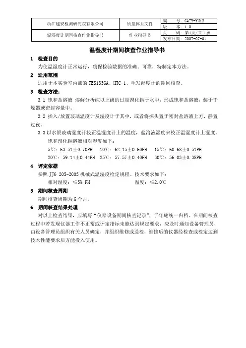
3.1 饱和盐溶液溶解分析纯以上级的过量溴化钠于水中,形成饱和盐溶液,装于干燥器或密封容量中。
3.2 插入/放置玻璃温度计及湿度计于其中,或者将探头置于密封盐溶液上方,静置过夜。
3.3以水银玻璃湿度计校正温湿度计上的温度,盐溶液湿度来校正温湿度计上湿度。
饱和溴化钠溶液相对湿度如下:
5℃:63.51±0.70PH 10℃:62.15±0.60PH 15℃:60.68±0.51PH 20℃:59.14±0.44PH 25℃:57.57±0.40PH 30℃:56.03±0.38PH
4 评定依据
参照JJG 205-2005机械式温湿度检定规程。
技术要求如下:
相对湿度:≤5% PH 温度:≤2.0℃
5 期间核查周期
期间核查周期为6个月。
6 期间核查结果处理
对以上检查结果,应填写“仪器设备期间核查记录”,于年底统一归档。
在期间核查过程中若发现仪器工作不正常或评定指标未能达到规定要求,应及时通知设备管理员,由设备管理员组织有关人员确定,并组织维修或送检,维修后的仪器经检查或检定达到技术性能要求后方能投入使用。
温湿度计期间核查作业指导书
1.核查目的
1.1 利用期间核查以保持温湿度计检定状态的可信度。
2.核查方式
2.1 由同一名检测人员依据JJG205-2005机械式温湿度计检定规程进行操作,对温湿度计的外观、温度计数误差、湿度计数误差进行核查。
3.核查步骤
3.1 调试设备至完好稳定状态,应充满电并保持仪器的稳定。
3.2 用肉眼对观察仪器的外观。
3.3 利用经计量检测部门检定且在有效期内温湿度计与仪器进行相互比对。
3.5 认真记录结果,便于分析比较。
3.6 试验温度湿度应控制稳定。
3.7 由公司技术和质量负责人及质管办主任负责核查监督工作。
4.分析与评价
4.1 依据JJG205-2005机械式温湿度计检定规程,温湿度计在调试完好、稳定的状态下温湿度计的外观完整,示值误差小于5%、重复性误差小于3%。
4.2 如果超出4.1条要求,应分析查找原因,如还是超出要求,则应对温湿度计请厂家及专业人士进行维修,提前进行检定。
CONTENTSUnpacking Instructions ........... 2 Package Contents .................. 2 Product Registration ............... 2 Features & Benefits: Sensor ..... 2 Features & Benefits: Display .... 3 Setup .................................... 4 Sensor Setup ......................... 4 Display Setup ........................ 5 Set Time & Units (6)Placement Guidelines (7)Using the Thermometer........... 8 Troubleshooting ..................... 9 Care & Maintenance.............10 Specifications ........................10 FCC Information ...................10 Customer Support .................11 Warranty (11)Questions? Contact Customer Support at(877) 221-1252 or visit www.AcuRite .com.Congratulations on your new AcuRite product. To ensure the best possible product performance, please read this manual in its entirety and retain it for future reference.Unpacking InstructionsRemove the protective film that is applied to the LCD screen prior to using this product. Locate the tab and peel off to remove.Package Contents1. Display with tabletop stand2. Wireless Sensor3. Instruction ManualFeatures & Benefits1 23 45WIRELESS SENSOR1. Integrated Hanger For easy placement.2. Wireless Signal Indicator Flashes when data is being sent to the display.3. Battery Compartment4. A-B-C Switch ID code that identifies the sensor on the display.5. Battery Compartment CoverSET13Features & BenefitsDISPLAY FRONTDISPLAY BACKpmDISPLAY FRONT1. being viewed.2.(see page 8).3. being viewed.4. Clock5. Current Display Temperature6. Display Low Battery Indicator7. Sensor Low Battery Indicator8. Sensor Signal Strength9. Sensor Indicator10. Current Sensor Temperature For selected sensor (#9).1817 16 1514 12DISPLAY BACK11.Battery Compartment Cover 12. Display Stand 13. Battery Compartment 14. °F/°C Switch Press to select temperature units. 15. ▼ Button For setup preferences and viewing records.16. SET Button For setup preferences.17. ▲Button For setup preferences and viewing records.18. Integrated Hang Hole For easy wall mounting.1 2 3 4 1Sensor Setup1 Set the A-B-C SwitchThe A-B-C switch is located inside the battery compartment. It can be set to A, B or C. However, you must select different letter choices for each of the sensors if you are synchronizing more than one. 2 Install or Replace BatteriesAcuRite recommends high quality alkaline or lithium batteries for the best product performance. Heavy duty or rechargeable batteries are not recommended. The sensor requires lithium batteries in low temperature conditions. Cold temperatures can cause alkaline batteries to function improperly. Use lithium batteries in the sensor for temperatures below -4ºF / -20ºC.1. Slide off the battery compartment cover. Take note of the A-B-C switch setting inside the battery compartment.2. Insert 2 x AA batteries into the battery compartment, as shown. Follow the polarity (+/-) diagram in the battery compartment.3. Replace the battery cover.4. Repeat steps 1-3 to setup additional sensors (if applicable; sold separately).NOTE:The A-B-C switch positions must differ between each sensor. Verify that each sensor has a different channel selected bychecking the switch position in the battery compartment.A B C1A-B-C SwitchDisplay SetupInstall or Replace Batteries1. Remove the battery compartment cover.2. Insert 3 x AAA alkaline batteries into the battery compartment, as shown. Follow the polarity (+/-) diagram in the battery compartment.3. Replace the battery cover.SETInstall Batteriesbatteries properly. Only batteries of the same or equivalent type as recommended are to be used. DO NOT incinerate used batteries. DO NOT dispose of batteries in fre, as batteries may explode or leak. DO NOT mix old and new batteries or types of batteries (alkaline/standard). DO NOT use rechargeable batteries. DO NOT recharge non-rechargeable batteries. DO NOT short-circuit the supply terminals.Set the Time & UnitsPress and hold the “SET” button, located on the back of the display, to enter SET MODE. Once in set mode, the preference you are currently setting will blink on the display.To adjust the currently selected (flashing) item, press and release the “▲” or “▼“ buttons (press and HOLD to fast adjust).To save your adjustments, press and release the “SET” button again to adjust the next preference. The preference set order is as follows:CLOCK HOURCLOCK MINUTETEMPERATURE UNITS (ºF or ºC)**You may also select between degrees Fahrenheit (°F) or Celsius (°C) temperature units after setup by pressing and releasing the °F/°C button, located inside the battery compartment.You will automatically exit SET MODE if no buttons are pressed for 8 seconds. Enter setup mode at any time by pressing and holding the “SET” button.Expand the SystemThe display features built-in sensors for measuring temperature at its location. The display can be expanded to track additional areas by using compatible Temperature Sensors (optional; sold separately). Add up to 3 indoor/outdoor sensors to observe conditions in additional locations within 330 ft (100 m). Compatible Sensors are available at: Placement for Maximum AccuracyAcuRite sensors are sensitive to surrounding environmental conditions. Proper placement of both the display and wireless sensor are critical to the accuracy and performance of this product.Sensor is water resistant and is designed for indoor or outdooruse, however, to extend its life place the sensor in an areaprotected from direct weather elements. The sensor may also beplaced indoors to measure environmental conditions.Hang the sensor using the integrated hang holes or hanger, orby using string (not included) to hang it from a suitable location,like a well covered tree branch. The best location is 4 to 8 feetabove the ground with permanent shade and plenty of fresh airto circulate around the sensor.Important Placement Guidelines•To ensure accurate temperature measurement, place units out of direct sunlight and away from heat sources or vents.•Display and wireless sensor must be within 330 ft (100 m) of each other. •To maximize wireless range, place units away from large metallic items, thick walls, metal surfaces, or other objects that may limit wireless communication.•To prevent wireless interference, place both units at least 3 ft (.9 m) away from electronic devices (TV, computer, microwave, radio, etc.)Setup is CompleteThe sensor(s) will now synchronize with the display. It may take a few minutes for synchronization to complete. Please refer to the troubleshooting section of this manual if anything appears to be functioning improperly.Using the ThermometerHigh & Low RecordsToday’s high and low temperatures are recorded for both the display and the wireless sensor(s). Today’s records automatically clear at 12:00am midnight every day.▲” button▲” or “▼“ buttons to cycle through the high records for each wireless sensor.▼“ button▲” or “▼“ buttons to cycle through the low records for each wireless sensor.View Temperature ReadingsThe thermometer displays the current temperature readings for both the display and the wireless sensor(s).If the thermometer is being used with more than one wireless sensor, toggle between each sensor’s readings by pressing and releasing the “▲” or “▼“ buttons on the back of the display.In auto-cycle mode, the display will automatically cycle through the data available for each wireless sensor. Auto-cycle mode can be activated by▲” or “▼“ buttons on the back of the display untilThe Sensor Indicator is used to determine which sensor readings you are viewing. For example, if the Sensor Indicator is displaying “A”, the readings are being transmitted from the sensor with the A-B-C switch set to “A.”TroubleshootingIf your AcuRite product does not operate properly after trying the troubleshooting steps, visit or call(877) 221-1252 for assistance.Care & MaintenanceDisplay CareClean with a soft, damp cloth. Do not use caustic cleaners or abrasives. Keep away from dust, dirt and moisture. Clean ventilation ports regularly with a gentle puff of air.Wireless Sensor CareClean with a soft damp cloth. Do not use caustic cleaners or abrasives. SpecificationsTEMPERATURE RANGE Sensor: -40ºF to 158ºF; -40ºC to 70ºCDisplay: 32ºF to 122ºF; 0ºC to 50ºCWIRELESS RANGE 330 ft / 100m depending on home construction materials WIRELESS FREQUENCY 433 MHzPOWER Display: 3 x AAA alkaline batteriesSensor: 2 x AA alkaline or lithium batteriesDATA REPORTING Sensor Data: 16 secondsDisplay Data: 60 secondsFCC InformationThis device complies with part 15 of FCC rules. Operation is subject to the following two conditions:1- This device may NOT cause harmful interference, and2- This device must accept any interference received, including interference that may cause undesired operation. WARNING: Changes or modifications to this unit not expressly approved by the party responsible for compliance could void the user’s authority to operate the equipment.NOTE: This equipment has been tested and found to comply with the limits for a Class B digital device, pursuant to Part 15 of the FCC rules. These limits are designed to provide reasonable protection against harmful interference in a residential installation. This equip-ment generates, uses and can radiate radio frequency energy and, if not installed and used in accordance with the instructions, may cause harmful interference to radio communications. However, there is no guarantee that interference will not occur in a particular installation. If this equipment does cause harmful interference to radio or television reception, which can be determined by turning the equipment off and on, the user is encouraged to try to correct the interference by one or more of the following measures:• Reorient or relocate the receiving antenna.• Increase the separation between the equipment and the receiver.• Connect the equipment into an outlet on a circuit different from that to which the receiver is connected.• Consult the dealer or an experienced radio/TV technician for help.NOTE: The manufacturer is not responsible for any radio or TV interference caused by unauthorized modifications to this equipment. Such modifications could void the user authority to operate the equipment.This device complies with Industry Canada licence-exempt RSS standard(s).Operation is subject to the following two conditions:(1) This device may not cause interference, and(2) This device must accept any interference received, including interference that may cause undesired operation of the device.Customer Support AcuRite customer support is committed to providing you with best-in-class service. For assistance , please have the model number of this product available and contact us in any of the following ways: (877) 221-1252Visit us at www.AcuRite .com► Installation Videos► Register your Product ► Instruction Manuals► Support User Forum ► Replacement Parts ► Submit Feedback & IdeasLimited One Year Warranty At AcuRite, we proudly uphold our commitment to quality technology. Chaney Instrument Co. warrants that all products it manufactures to be of good material and workmanship, and to be free of defects when properly installed and operated for a period of one year from the date of purchase. We recommend that you visit us at for the fastest way to register your product. However, product registration does not eliminate the need to retain your original proof of purchase in order to obtain warranty benefits. Chaney Instrument Co. warrants that all products it manufactures to be of good material and workmanship, and to be free of defects when properly installed and operated for a period of one year from the date of purchase. Remedy for breach of this warranty is limited to repair or replacement of the defective item(s). Any product which, under normal use and service, is proven to breach the warranty contained herein within ONE YEAR from date of sale will, upon examination by Chaney, and at its sole option, be repaired or replaced by Chaney. Transportation costs and charges for returned goods shall be paid for by the purchaser. Chaney hereby disclaims all responsibility for such transportation costs and charges. Thiswarranty will not be breached, and Chaney will give no credit for products it manufactures which have received normal wear and tear, been damaged (including by acts of nature), tampered, abused, improperly installed, damaged in shipping, or repaired or altered by others than authorized representatives of Chaney. The above-described warranty is expressly in lieu of all other warranties, express or implied, and all other warranties are hereby expressly disclaimed, including without limitation the implied warranty of merchantability and the implied warranty of fitness for a particular purpose. Chaney expressly disclaims all liability for special, consequential or incidental damages, whether arising in tort or by contract from any breach of this warranty. Some states do not allow the exclusion or limitation of incidental or consequential damages, so the above limitation or exclusion may not apply to you. Chaney further disclaims all liability from personal injury relating to its products to the extent permitted by law. By acceptance of any of Chaney’s products, the purchaser assumes all liability for the consequences arising from their use or misuse. No person, firm or corporation is authorized to assume for Chaney any other liability in connection with the sale of its products. Furthermore, no person, firm or corporation is authorized to modify or waive the terms of this paragraph, and the preceding paragraph, unless done in writing and signed by a duly authorized agent of Chaney. This warranty gives you specific legal rights, and you may also have other rights which vary from state to state. For in-warranty claims:Chaney Instrument Co. 965 Wells St., Lake Geneva, WI 53147 11Weather Temperature Weather Kitchen Clocks Stations & Humidity Alert Radio Thermometers& TimersIt’s more than accurate, it’sAcuRite offers an extensive assortment of precision instruments, designed to provide you with information you can depend on toPlan your day with confidence™.©Chaney Instrument Co. All rights reserved. AcuRite is a registered trademarkof the Chaney Instrument Co., Lake Geneva, WI 53147. All other trademarks and Printed in China copyrights are the property of their respective owners. AcuRite uses patented 02059M INST 011216 technology. Visit /patents for details.。
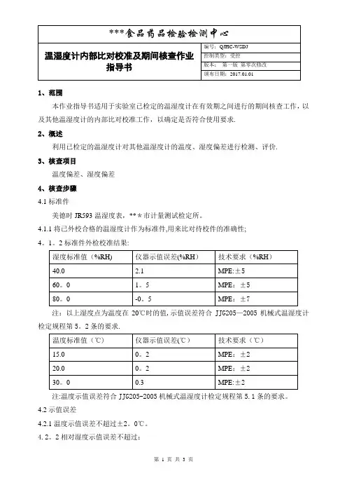
1、范围本作业指导书适用于实验室已检定的温湿度计在有效期之间进行的期间核查工作,以及其他温湿度计的内部比对校准工作,以确定是否符合使用要求.2、概述利用已检定的温湿度计对其他温湿度计的温度、湿度偏差进行检测、评价.3、核查项目温度偏差、湿度偏差4、核查步骤4.1标准件美德时JR593温湿度表,***市计量测试检定所。
4.1.1将已外校合格的温湿度计作为标准件,用来比对待校件的准确性;4。
1。
2标准件外检校准结果:注:以上湿度点为温度在20℃时的值,示值误差符合JJG205—2005机械式温湿度计检定规程第5。
2条的要求.注:温度示值误差符合JJG205-2005机械式温湿度计检定规程第5.1条的要求。
4.2示值误差4.2.1温度示值误差不超过±2。
0℃。
4.2。
2相对湿度示值误差不超过:4.2。
2。
1 ±5%RH(40%RH-70%RH,20℃);4。
2.2。
2 ±7%RH(40%RH以下或70%RH以上,20℃)。
4。
3待校件外观检查4。
3。
1待校件各部件完好,无明显损伤,表面无刮痕、锈蚀等。
4。
3。
2标识完整,无掉落、撕裂。
4。
3.3读数、刻度线清晰可辨,指针平直,可灵活转动.4.4待校件测量比对4。
4。
1将待校件及标准件放入同一房间,静置2小时后分别读数,先读标准件,再读待校件,间隔30min后重复读数一次。
4。
4。
2所读实际示值减去1。
2条所示的偏差值为本次标准件的示值。
4.4。
3取两次读数的算术平均值为标准件和待校件的温度示值(TB 和T)及湿度示值(HB和H),示值误差分别为△T=T—TB ;△H=H-HB(△T与△H分别满足2.1和2。
2的要求).4。
5核查周期机械式温湿度计的核查周期定为6个月。
凡在使用过程中经过修理或示值调整的,均需重新检定。
编制: *** 审核:******食品药品检验检测中心 ZL-060温湿度计内部比对校准记录表第 3 页共3 页。
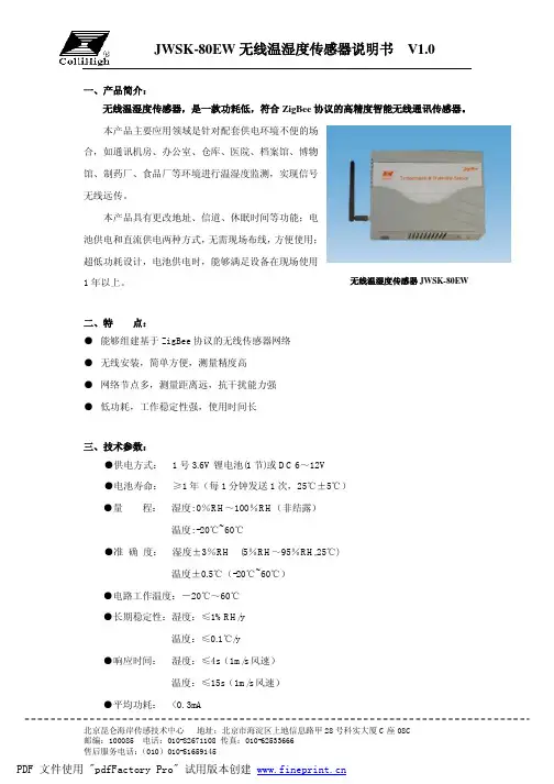
一、产品简介:无线温湿度传感器,是一款功耗低,符合ZigBee 协议的高精度智能无线通讯传感器。
本产品主要应用领域是针对配套供电环境不便的场合,如通讯机房、办公室、仓库、医院、档案馆、博物馆、制药厂、食品厂等环境进行温湿度监测,实现信号无线远传。
本产品具有更改地址、信道、休眠时间等功能;电池供电和直流供电两种方式,无需现场布线,方便使用;超低功耗设计,电池供电时,能够满足设备在现场使用1年以上。
二、特 点:● 能够组建基于ZigBee 协议的无线传感器网络● 无线安装,简单方便,测量精度高● 网络节点多,测量距离远,抗干扰能力强● 低功耗,工作稳定性强,使用时间长三、技术参数:●供电方式: 1号3.6V 锂电池(1节)或DC 6~12V●电池寿命: ≥1年(每1分钟发送1次,25℃±5℃)●量 程: 湿度: 0%RH ~100%RH (非结露)温度: -20℃~60℃●准 确 度: 湿度±3%RH (5%RH ~95%RH,25℃)温度±0.5℃(-20℃~60℃)●电路工作温度:-20℃~60℃●长期稳定性:湿度:≤1%RH/y温度:≤0.1℃/y●响应时间: 湿度:≤4s (1m/s 风速)温度:≤15s (1m/s 风速)●平均功耗: <0.3mA无线温湿度传感器JWSK-80R (E )无线温湿度传感器JWSK-80EW●通讯频段: 2.4GHz●信道数量: 16●设备地址: 0~99●传输距离:800米(空旷距离)●壳体尺寸:180mm × 130mm × 53mm(不包括天线)●安装方式:壁挂式:固定墙面注:出厂默认设备地址为01,信道为26四、使用说明:1、本产品配合JWSK-C0C组建无线传感器网络使用。
2、硬件参数设置及正常使用:A 电池供电时,短路SW3的OFF和VB,短路JP2的PROG端,短路JD9,JD1,JD2,将本产品通过串口与PC机相连,将KS1开关拨到ON,将电池装入电池盒内,电源指示灯D9亮,通讯指示灯DB2亮,即可修改地址、信道、休眠时间等参数,见“测试软件参数设置”。
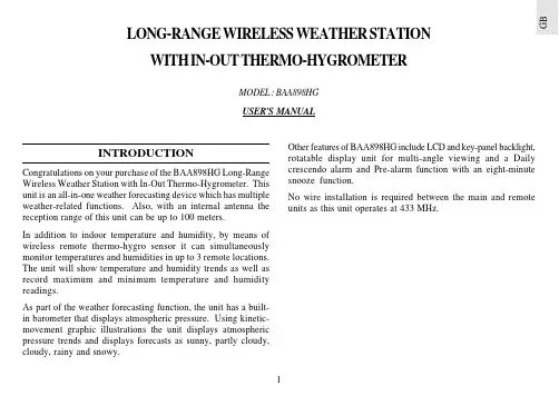
G BINTRODUCTIONCongratulations on your purchase of the BAA898HG Long-Range Wireless Weather Station with In-Out Thermo-Hygrometer. This unit is an all-in-one weather forecasting device which has multiple weather-related functions. Also, with an internal antenna the reception range of this unit can be up to 100 meters.In addition to indoor temperature and humidity, by means of wireless remote thermo-hygro sensor it can simultaneously monitor temperatures and humidities in up to 3 remote locations.The unit will show temperature and humidity trends as well as record maximum and minimum temperature and humidity readings.As part of the weather forecasting function, the unit has a built-in barometer that displays atmospheric pressure. Using kinetic-movement graphic illustrations the unit displays atmospheric pressure trends and displays forecasts as sunny, partly cloudy,cloudy, rainy and snowy.LONG-RANGE WIRELESS WEATHER STATION WITH IN-OUT THERMO-HYGROMETERMODEL : BAA898HG USER'S MANUALOther features of BAA898HG include LCD and key-panel backlight,rotatable display unit for multi-angle viewing and a Daily crescendo alarm and Pre-alarm function with an eight-minute snooze function.No wire installation is required between the main and remote units as this unit operates at 433 MHz.A. LCD DISPLAYA1.WEATHER FORECAST WINDOW- Graphically illustrates a weather forecast- Indicates trends in atmospheric pressure- Indicates when main unit battery is lowA2.TEMPERATURE WINDOW-Displays current, minimum or maximum indoor and remotetemperature-Indicates temperature trendA3.HUMIDITY WINDOW-Displays current, minimum or maximum indoor and remotehumidity-Indicates humidity trend-Displays the Comfort Level-Indicates when the battery of the remote sensor is lowA4.ATMOSPHERIC PRESSURE WINDOW-Displays the current or historical (last 24 hours) barometricreadingA5.TIME / DATE / ALARM WINDOW-Displays the current time, date (day, month, and year),daily alarm or Pre-alarm function B. CONTROL BUTTONS - FRONT PANELB1.[ MODE ] BUTTON-Changes the display mode of the clock, and alters time/date settingB2.[ ] BUTTON-Displays the daily alarm time and Pre-alarm time period, orchanges the corresponding alarm timeG BB3.[ MEMORY ] BUTTON-Displays minimum and maximum temperature and humidity readings, and erases memory data B4.[ CHANNEL ] BUTTON- Displays the temperature and humidity readings of the indoor or remote sensor B5.[ SNOOZE / LIGHT ] BUTTON- Activates the snooze function or turn on the backlight B6.DETACHABLE TABLE - STAND( [ SNOOZE / LIGHT ] STAND - BUTTON)-Acts as the [ SNOOZE / LIGHT ] BUTTON when attached to the display unitC. CONTROL BUTTONS - SIDE PANELC1 & C2. UP [ ] & DOWN [ -Increase or decrease in the value of a setting respectively.D. CONTROL BUTTONS - BACK PANELD1.BATTERY COMPARTMENT-Accommodates four (4) pieces of UM-3 or "AA" size batteriesD2.[ HISTORY ] BUTTON-Displays the barometric reading for the last 24 hours, or enter the altitude compensation settingG BD3.[ mb / hPa - inHg ] SLIDE SWITCH-Selects between "mb / hPa" or "inHg" pressure unit display D4.[ °C / °F ] SLIDE SWITCH-Selects between Centigrade (°C ) or Fahrenheit (°F)temperature unit display D5.[ RESET ] BUTTON-Resets the unit by returning all setting to their default valuesFEATURES : REMOTETHERMO-HYGRO SENSOR THGR228Na.Two-line LCDDisplays the current temperature and humidity monitored by the remote unit b.LED indicatorFlashes when the remote unit transmits a reading c.°C/°F slide switchSelects between Centigrade (°C) and Fahrenheit (°F)d.Channel slide switchDesignates the remote unit Channel 1, Channel 2 or Channel 3e.RESETReturns all settings to default values f.Battery compartmentAccommodates two (2) pieces of UM-4 or AAA-size g.Battery doorh.Wall-mount holderSupports the remote unit in wall-mounting i.Removable table standFor standing the remote unit on a flat surfaceG BBEFORE YOU BEGIN -INSTALLING THE TABLE STANDBefore operation, plug the detachable table stand into the display unit as shown.1.Insert batteries for the main unit first. Then proceed with inserting the batteries for the remote unit.2.Position the remote unit and the main unit within effective transmission range. In usual circumstances, the effective range is up to 100 meters.3.Though the remote unit is weather proof, it should be placed away form direct sunlight, rain or snow.BATTERY INSTALLATION: MAIN UNIT1.Gently open the battery compartment door as shown.2.Insert four (4) pieces of UM-3 or "AA" size batteries in accordance with the polarities shown.3.Close the battery compartment door.BATTERY AND CHANNEL INSTALLATION:REMOTE UNITThe remote thermo-hygro sensor unit uses two (2) UM-4 or “AAA” size batteries.G BFollow these steps to install / replace batteries:1.Remove the screws on the battery compartment.2.Select the channel number on the CHANNEL slide switch.3.Select the temperature display unit on the °C/°F slide switch.4.Insert the batteries strictly according to the polarities shown therein.5.Replace the battery compartment door and secure its screws.Replace the batteries when the low-battery indicator of the particular channel lights up on the main unit.Note that once a channel is assigned to a remote unit, you can only change it by removing the batteries or resetting the unit.LCD AND KEY-PANEL BACKLIGHTFor easy viewing in the dark this unit is featured with backlight function on the LCD display as well as on the front key-panel.Also, this unit is specially designed so that the backlight can be operated differently no matter it is wall-mounted or being put on the table.Table-StandPress the corresponding button once. The backlight will be activated for 5 seconds.SETTING THE CLOCK ANDCALENDAR1.Press and hold [ MODE ] button for three seconds. The 12-hr2.Press [ MODE ] button again, the hour will flash. Use the [3.Press [ MODE ] button again to confirm. Repeat the above steps to set the minute, year, day/month or month/day display format, month, day and language for day-of-week respectively.4.Press [ MODE ] button to confirm and exit the settings.G B5.For the language for day-of-week, you can select E for English,D for German, F for French, I for Italian or S for Spanish. The day-of-week can be expressed as an abbreviation in five different languages. The languages and their selected abbreviations for each day of the week are shown in the language chart below.Note : When changes are made to the minute, the seconds will start from zero.SETTING THE ALARMTo set the Alarm:1.Press [] button to display the daily alarm time (the icon "AL" will be displayed)2.Press and hold [ ] for three seconds and the value for thehour will flash.3.Press [ setting.4.Press [] 5.Press [] to exit.The alarm will be automatically activated. The ALARM ON icon [ To deactivate the daily alarm function, press the [ the alarm time is displayed. The ALARM ON and [ - : -- ] to display the alarm time again.ALARM AND SNOOZE FUNCTIONWhen the daily alarm goes off, the backlight will be on for five seconds and the alarm-on icon will flash.Initially the active alarm will have a gentle sound. The intensity will increase in three stages. Without interruption, the unit will alarm for 2 minutes.To stop the alarm sound, press any button (expect [ MEMORY ]& [ CHANNEL ] buttons).If the [ SNOOZE / LIGHT ] button or stand-button is pressed, the snooze function will be triggered. The alarm sound will stop and the alarm-on icon will blink for eight minutes. After that the alarm will go off again.To deactivate the SNOOZE function, press the [] button.LanguageMondayEnglish German French Italian SpanishCHANNEL 1 REMOTE SENSORThe alarm function also has a pre-alarm feature which can alert the user before the preset alarm time when weather condition changes. This pre-alarm function applies to Channel 1 Remote Sensor only.To enable this function:1.First activate the alarm function. Then enter the Pre-Alarmmode by pressing the [ ] button twice. The "PRE-AL" icon will be displayed.2.Press and hold the [ ] button for 3 seconds to set theoperating time interval for this pre-alarm function. Use the [3.Press the [ ] button to confirm and exit. The pre-alarmfunction will be enabled automatically which is indicated by the appearance of the [ ] symbol.4.mode. The [ ] symbol will disappear and [ - : -- ] will appear to indicate disable of this function.The pre-alarm will operate during the selected time interval before the daily alarm time.During the pre-alarm operating period, if the temperature recorded at Channel 1 remote sensor falls to or below 2.0ºC, the pre-alarm will be triggered. For example, if the daily alarm is set to go off at 7:00 am and the pre-alarm operating time interval is set to 45minutes, the pre-alarm will start to operate at 6:15 am (45 minutes before 7:00 am). The Pre-Alarm icon will flash and the backlight will be turned on for 5 seconds. An alarm sound will also go off for 2 minutes as that of the daily alarm and the snooze function will also be activated if the [ SNOOZE / LIGHT ] button or stand-button is pressed.Note: The daily alarm will NOT function until the next day if the pre-alarm has been triggered beforehand. Deactivation of the alarm function will disable the pre-alarm feature automatically.NOTE ON REMOTE READINGSOnce batteries are in place in the remote unit, it will start transmitting samplings at 40-second intervals. If no signals are received when the remote sensor display is selected, "--- " will be displayed. To force the main unit to search for remote sensor signals, press [ MEMORY ] and [ CHANNEL ] simultaneously. If that fails, check that the remote sensor is still in place. Make sure the transmission is within range and the path is clear of obstacles and interference. Repeat this procedure whenever you find discrepancies between the display on the main unit and the display on the remote sensor.CHECKING INDOOR AND REMOTETEMPERATURES & HUMIDITIESTo display the indoor and outdoor temperature and humidity readings, press the [ CHANNEL ] button to toggle among the indoor, Channel 1, 2 and 3 displays.G BThe temperature can be shown in Centigrade (°C) or Fahrenheit (°F). Select the appropriate reading by using the [ °C / °F ] slide switch (located in the battery compartment). Slide the switch to °C for Centigrade or °F for Fahrenheit.If the reading goes above or below the specified amounts, the display will show a flashing "HHH" or "LLL".This unit has an auto-scan function that can sequentially display the indoor and remote readings. To activate this function, press and hold the [ CHANNEL ] button for 3 seconds. To deactivate press the [ CHANNEL ] button again.NOTE ON °C AND °FThe outdoor temperature display on the main unit is dominated by the selection on the [ °C / °F ] slide switch of the main unit.Whatever the display unit of the remote sensor is, it will only apply to the remote sensor itself and the temperature will be automatically converted to the chosen one of the main unit.MAXIMUM AND MINIMUM TEMPERATURES & HUMIDITIESThe maximum and minimum recorded temperatures and humidities will be automatically stored in memory. To display them, press [ MEMORY ] . Press [ MEMORY ] again to alternate between the maximum, minimum and current readings. The respective MAX or MIN indicator will be displayed.To clear the memory, press [ MEMORY ] and hold for three seconds. The maximum and minimum recorded readings will beerased. Subsequently, if you press [ MEMORY ] after the memory has been erased, the maximum and minimum readings will have the same values as the current ones.TEMPERATURE & HUMIDITY TRENDThe temperature and humidity trend indicator shows the trend of temperatures and humidities collected at that particular sensor.Three trends: rising, steady, and falling will be shown.ATMOSPHERIC PRESSUREThe atmospheric pressure arrow indicator will indicate if the atmospheric pressure is increasing, remaining stable, or decreasing.NOTE:1. The accuracy of a general pressure-based weather forecast isabout 70% to 75%.2. The weather forecasts from this unit are predictions thatcover the next 12 to 24 hours. It may not necessarily reflect the current situation.3. The "Sunny" icon, as applies to night time, implies clearweather.COMFORT LEVEL INDICATORSThe comfort level indicators COM, WET or DRY will tell you if the current environment is comfortable, too wet or too dry.The comfort indicator will appear on the display when the following conditions are satisfied:HOW TO CHECKTHE BAROMETRIC PRESSUREThe current and historical barometric pressure is shown on the atmospheric pressure window.For monitoring the local barometric pressure reading, "0" meter (preset value) should be selected for the altitude setting. For monitoring the Sea Level barometric pressure reading at certain altitude, the local altitude should be selected as the altitude setting. To set the altitude, press and hold [ HISTORY ] button to enter the altitude compensation setting mode. Use the [[appropriate). Press [ HISTORY ] button to confirm and exit. The atmospheric pressure can be displayed in mb/hPa or inHg. The pressure unit is selected on the atmospheric pressure slide switch inside the battery compartment.If you want to check the pressure history for a particular hour during the past 24 hours, press the [ HISTORY ] button. Each press on the button will go back by an hour. Holding down the button will increase the value rapidly.LOW BATTERY INDICATIONWhen it is time to replace batteries, the respective low battery indicator [ ] will show up when the corresponding channel is selected. The battery level of the main unit is shown on the Weather Forecast Window when it is running low.TABLE STAND (REMOTE UNIT)As for the remote unit, it comes with a wall-mount holder and a removable stand. Use either to hold the unit in place.Wall-Mount:Table-Stand:HOW TO WALL MOUNT OR USE THETABLE STAND (MAIN UNIT)The unit can be wall-mounted using its recessed screw holes orplaced on a flat surface using the detachable table stand.Table-Stand:Gently plug in the table stand as shown:HOW TO RESET THE UNITThe [ RESET ] button allows you to return all settings to factory values. Accessing the slot is required only when the unit is not operating in a favorable way such as in the rare case of a malfunction.The [ RESET ] slot is located inside the battery compartment door. To use the button:1. Open the battery compartment door.2. Place a blunt stylus into the hole and press.3. Close the battery compartment door.MAINTENANCEWhen handled properly, this unit is engineered to give you years of satisfactory service. Here are a few product care instructions:1.Do not immerse the unit in water. If the unit comes in contact with water, dry it immediately with a soft lint-free cloth.2.Do not clean the unit with alcohol containing detergent,abrasive or corrosive materials. Abrasive cleaning agents may scratch the plastic parts and corrode the electronic circuit.3.Do not subject the unit to excessive: force, shock, dust,temperature, or humidity. Such treatment may result in malfunction, a shorter electronic life span, damaged batteries,or distorted parts.4.Do not tamper with the unit's internal components. Doing so will terminate the unit's warranty and may cause damage. The unit contains no user-serviceable parts.5.Only use new batteries as specified in this instruction manual.Do not mix new and old batteries as the old batteries may leak.6.Read this instruction manual thoroughly before operating the unit.SPECIFICATIONSMain unitIndoor Temperature measurement Proposed operating range :-5.0°C to +50.0°C (23.0°F to 122.0°F)Temperature resolution :0.1°C (0.2°F)G BRelative Humidity measurement Measuring Range :25% RH to 95% RH at 25°C (77°F)Humidity Resolution:1% RHRemote unitRF Transmission Frequency :433 MHz No. of Remote unit :Up to 3 units RF Transmission Range :Up to 100 meters Data sensing cycle :around 40 secondsTemperature measurement Display range:-20.0°C to +60.0°C (-4.0°F to 140.0°F)Proposed operating range :-5.0°C to +60.0°C (23.0°F to 140.0°F)Temperature resolution:0.1°C (0.2°F)Relative Humidity measurement Measuring Range :25 to 95%RH at 25°C (77°F)Humidity Resolution:1% RHBarometric Pressure measurement Pressure measuring range :795 to 1050mb / hPa (23.48 to 31.01 inHg)Power Main unit:uses four (4) UM-3 or "AA"1.5V batteriesRemote sensing unit:uses two (2) UM-4 or "AAA"1.5V batteriesWeight Main unit:300gm (without battery)Remote sensing unit :63gm (without battery)Dimensions Main unit:195 (L) x 105 (W) x 77 (T) mm Remote sensing unit:92 (L) x 60 (W) x 20 (T) mm CAUTION—The content of this manual is subject to change withoutfurther notice.—The technical specifications of this product are subjectto change without notice.—Due to printing limitation, the displays shown in thismanual may differ from the actual display.—The contents of this manual may not be reproducedwithout the permission of the manufacturer.This product contains the approved transmitter module TX 01 and complies with the essential requirements of Article 3 of the R&TTE 1999/5/EC Directives, if used for its intended use and that the following standard(s) has/ have been applied:Efficient use of radio frequency spectrum(Article 3.2 of the R&TTE Directive)applied standard(s)EN 300 220-1(2,3):1997 Electromagnetic compatibility(Article 3.1.b of the R&TTE Directive)applied standard(s)ETS 300 683:1997Safety of information technology equipment(Article 3.1.a of the R&TTE directive)applied standard(s)EN 60950:1997 Additional information:The product is therefore conform with the Low V oltage Directive 73/23/EC, the EMC Directive 89/336/EC and R&TTE Directive 1999/5/EC (appendix II) and carries the respective CE marking.VS-Villingen / Germany August 2001Gerhard PreisR&TTE Representative of manufacturer RTTE Compliant Countries :All EC countries, Switzerland CH And Norway N。
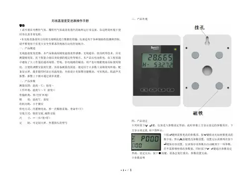
无线温湿度变送器操作手册警告·请不要在可燃性气体、爆炸性气体或者有蒸汽的场所运行本仪表。
在这样的环境下使用本仪表非常危险。
·本无线设备使用公用的无线频段进行数据的传输,仪表适用于各种辅助性检测和控制,请不要使用于有重大安全性要求的现场自动化控制场合。
一、产品概述无线温湿度变送器,本产品集成高精度温湿度传感器、无线通信、低功耗等技术,具有测量精度高、抗干扰能力强以及较强的稳定性等特点。
本产品以电池供电,在工程实施中避免了大工作量的通讯线缆、管线、供电线路的铺设,用户也可根据现场实际使用情况,方便的调整安装的位置。
该设备测量范围宽,能适用于大多数工业级使用环境;配备显示屏,最多能同时显示双温度值;内部设计有报警功能模块,可实现高、低温声光报警;报警上下限可通过菜单设置。
二、产品参数测量范围:温度~℃;湿度~工作环境:温度℃~℃湿度<传输距离:米(空旷环境)精度:温度℃,湿度待机功耗:小于微安供电方式:内置锂电池,秒一次数据采集,寿命年(℃)安装方式:壁挂安装,磁铁安装尺寸:**(长*宽*厚)定制:可定制大屏、外置探头的型号三、产品外观四、产品设定()同时按下键,仪表进入参数设定界面,此时屏幕上方显示设定的参数项目,下方显示设定值,如下图所示。
()按键到需要更改的参数项,按键移动光标到要更改的数字处,然后按键更改参数设置,设置完后需要再次按下键保存该设置,仪表保存该参数后自动跳到下一项参数,若不需要继续修改参数值,同时按下键退出参数设定界面。
设定完后,按下按键,设备会复位重启,参数设置完成。
()参数说明~:系统保留,不要更改。
:温度修正系数,表示系数为~。
:温度零位修正,表示零位修正从~,设为表示零位修正:接收主机、网关地址:本机器地址:信道(波段)设置,需与接收主机、网关设置一致~:系统保留,不要更改。
:数据采样间隔,设置秒,建议不要少于秒。
~:系统保留,不要更改。
:无线发射功率,数字越大功率越大。
无线测温说明书一、简介无线测温是一种新型的测量温度的技术,通过无线传输的方式,实时监测物体的温度变化。
本说明书将介绍无线测温的原理、使用方法和注意事项,以帮助用户更好地了解和使用这一技术。
二、工作原理无线测温利用了物体在不同温度下发射的红外辐射,通过红外传感器将物体的辐射信号转化为电信号。
然后通过无线传输模块将这一电信号发送给接收器,接收器再将信号转化为温度数值进行显示。
三、使用方法1. 准备:首先要确保测温设备中的电池充足,以确保正常使用。
同时,需要在接收器和测温设备之间建立好无线连接,确保信号的稳定传输。
2. 测量:将测温设备对准需要测量温度的物体,保持适当距离,按下测温键进行测量。
测温时,设备会发出简短的信号提示,同时在显示屏上显示测量结果。
3. 记录:用户可根据需要将测量的温度数据进行记录,方便后续分析和比较。
四、注意事项1. 距离:在使用过程中,应保持一定的距离进行测温,距离过远或过近都可能导致测量误差。
通常建议距离物体3-5厘米。
2. 环境:确保测温环境没有强光照射或大量的粉尘,这可能会对测温结果产生干扰。
3. 物体表面:在测量时,应尽量选择物体表面平整光滑的位置进行测量,以获得更准确的结果。
4. 温度范围:请根据设备的规格和要求,选择适合的温度范围进行测量。
避免超出设备的测量范围,否则可能导致测量结果不准确。
5. 小样本测试:在测量液体或小尺寸物体的温度时,可使用特殊的测试头或环保套装,以确保测量的准确性。
免责声明:无线测温仅供参考,不作为判定温度的唯一依据。
对于测温过程中可能产生的误差,我们不承担任何责任。
五、维护与保养1. 清洁:当设备出现灰尘或污渍时,应使用柔软的干净布擦拭,不要使用有腐蚀性的溶液进行清洁。
2. 储存:如长时间不使用,请将设备放置在干燥通风的环境中,避免暴露于高温或潮湿的环境中。
3. 检修:如设备出现故障或异常,请及时联系专业维修人员进行检修,不要私自拆卸或维修。
温湿度计校准作业指导书1.0目的:保证计量仪器的有效使用,确保临床标本检验的质量。
2.0适用范围;XXXXX医院所有温湿度计。
3.0校准依据:3.1 CSB/QP-13《检测设备管理程序》3.2 JJG205-2005《机械式温湿度计检定规程》3.3 GB/T11605-2005《湿度测量方法》3.4 GB6999-1986《环境试验用相对湿度查算表》3.5 JJF1059-1999《测量不确定度评定与表示》4.0职责:4.1医学装备部计量管理人员负责计量仪器的校准工作。
4.2检验科相关使用部门配合计量管理人员进行校准工作。
5.0校准方法:5.1校准项目及要求﹕表15.2校准条件与设备:5.2.1校准条件环境温度:15~25℃范围内,温度波动不超过±3℃/6h﹔湿度:不大于75%RH﹔.5.2.2校准用标准器:恒温鼓风干燥箱1台,0~100℃温度计2只.5.3校准过程:5.3.1外观﹕采用目视观测。
5.3.1.1外型结构完好,无明显机械机械损伤,表面无划痕和锈蚀,无影响计量性能的缺陷。
5.3.1.2标志﹕有制造厂名,规格型号,许可证编号等。
5.3.1.3读数部分﹕a.刻度板正确而不倾斜,刻度线清晰均匀。
b.湿度刻度范围不小于30~95%RH,最小刻度不小于2%RH.。
c.温度刻度应不小于5~40℃,最小刻度应不小于1℃。
d.指针应平直,灵活转动,自由复位。
5.3.2. 温度示值误差5.3.2.1温度校准点:28℃.将恒温鼓风干燥箱的温度调节至28℃.5.3.2.2放入所要校准的温湿度计,恒温30min后,开始读数,先读恒温干燥箱的温度,再读温湿度计的温度,以后每隔5min读一次,重复读三次,取平均值.5.3.2.3结果计算: 应符合表1要求T平均=T1+T2+T3/3温度示值误差△T=T平均-T标准式中:△T----温湿度计的示值误差; ℃T平均----温湿度计测定的温度平均值; ℃T标准----恒温干燥箱设定的标准温度值;28℃5.3.3相对湿度示值误差5.3.3.1取2支型号规格相同的0~100℃温度计,一支做为干球温度计t,另一支在球部用洁净的纱布缠好(不得有皱折),并用蒸馏水充分湿润,做为湿球温度计tw,垂直悬挂于干燥箱内.5.3.3.2在恒温28℃30min的干燥箱内,开启鼓风机,3min后开始读数,先读湿球温度,再读干球温度,每隔1min读一次数,共读3次.(超过6min时需重新湿润纱布).计算每次测定的干,湿球温度差(t-tw).5.3.3.3根据干湿球的温度差,查GB6999-1986《环境试验用相对湿度查算表》,其中相关参数为:球状的温湿度计,类型为0.8型,t=28℃,详见表2.5.3.3.4根据测定的干湿温度差,查出相应的相对湿度,并记录校准温湿度计显示的相对湿度.取平均值进行比较.5.3.3.5结果计算: 应符合表1要求U测定平均=U测定1+U测定2+U测定3/3U标准平均= U标准1+U标准2+U标准3/3相对湿度示值误差△U= U测定平均- U标准平均式中: U测定平均----校准温湿度计显示的相对湿度; %RH U标准平均----干湿温度差查表的相对湿度%RH△U ----温湿度计的相对湿度示值误差; %RH表2 28℃时球状水银温度表相对湿度查算表P=110KPa, A=0.7947×10⁻¹C -1(0.8m/s)5.3.4温度重复性按5.3.2温度示值误差的三次温度测定值最大与最小值的差值即为温湿度计的温度重复性,应符合表1要求.温度重复性=T 最大-T 最小式中﹕T 最大-----三次测定温度时的最大值﹐℃T 最小-----三次测定温度时的最小值;℃5.3.5相对湿度重复性﹕按5.3.3相对湿度示值误差的测试方法﹐由温湿度计三次的显示值最大值与最小值的差值,即为温湿度计的相对湿度重复性,应符合表1要求。
Wireless Thermo-Hygro MonitorModel: WH0280Content1. Introduce (2)2. Get Started (2)2.1 Package Contents (2)2.2Recommend Tools (2)2.3 Thermometer Sensor Set Up (2)2.4 Display Console Set Up (4)3. Wireless Sensor Installation (6)3.1 Mounting with Zip Tie (7)4. Console Operation (7)4.1 Key function (7)4.2.Normal model (8)4.3 Time alarm model (9)4.4Min value model (9)4.5Max value model (10)4.6 Setting model (11)4.7. Setting model for alarm clock ................... 错误!未定义书签。
5.Sensor Resynchronization (10)6.Best Practices for Wireless Communication (10)7.Specifications (12)7.1.Wireless Specifications (12)7.2Measurement Specifications (12)7.3Power Consumption (12)8. Troubleshooting Guide (13)1. IntroduceThank you for your purchasing of this Wireless Indoor/Outdoor Thermometer with indoor humidity. To ensure the best product performance, please read this manual and retain it for future reference.2. Get StartedNote: The power up sequence must be performed in the order shown in this section: insert batteries in the remote sensor first, display console second.The weather station consists of a display console (receiver), and up to 3 thermometers (remote sensors), based on your order configuration.2.1 Package Contents2.2 Recommend ToolsHammer for hanging remote thermometer transmitter.2.3 Thermometer Sensor Set UpNote: Do not use rechargeable batteries. They tend to have a lower operating voltage, do not have a wide temperature range, and do not last as long as non-rechargeable batteries.We recommend fresh alkaline batteries for outdoor temperature ranges between -20°C and 60°C and fresh lithium batteries for outdoor temperature ranges between -40 °C and 60 °C.1.Remove the battery door on the back of the sensor by sliding thecompartment door down, as shown in Figure 1.2.Set RF sensor channel.Figure 13.Insert one AA battery in the back of the sensor4.After inserting the battery, the remote sensor LED indicator will lightfor 4 seconds, and then flash once per 60 seconds thereafter. Each time it flashes, the sensor is transmitting data.5.Close the battery door.2.4 Display Console Set Up1. Move the remote thermometer(s) about 2 to 3m away from thedisplay console (if the sensor is too close, it may not be received by the display console).2. Remove the battery door on the back of the display. Insert one AA(alkaline or lithium, avoid rechargeable) battery in the back of the display console.All of the LCD segments will light up for a few seconds to verify all segments are operating properly.Figure 23. Replace the battery door, and fold out the desk stand and placethe console in the upright position.The console will instantly display indoor temperature and humidity.The remote temperature will update on the display within a few minutes.While in the search mode, the reception search icon flash.Note: If the remote does not update, please reference the troubleshooting guide in Section.2.4.1 Display Console Layout2.4.2 Sensor Operation VerificationVerify the indoor and outdoor temperature match closely with the console and sensor array in the same location (about 2 to 3m apart). The sensors should be within 2°C (the accuracy is ±1°C. Allow about 30 minutes for both sensors to stabilize.3. Wireless Sensor InstallationIt is recommended you mount the remote sensor in a shaded area. Direct sunlight and radiant heat sources will result in inaccurate temperature readings. Although the sensor is water resistant, it is best to mount in a well-protected area, such as under an eve.3.1 Mounting with Zip TieMounting the sensor with a zip tie will result in better accuracy when mounting outside, since it is not touching other objects.Figure 43.2 Mounting with Nail or screwTo mount the sensor with a nail or screw, the cap must be less than or equal to 5mm in diameter.Figure 54. Console OperationThe console has two buttons at the back of console for easy operation. If no operation for 30s, display will return back to normal mode.There are five program modes available: Setting mode, Time Alarm Mode, MIN/MAX Mode, Loop display Mode and Sensor Register Mode4.1 Setting ModeWhile in normal display, press the MODE key for 2 seconds to enter Setting ModePress the MODE key to select the following settings in sequence:1. 12/24 Hour format2. Time setting (hour/minutes)3. Temperature unit (°C / °F)4. Complete setting mode and back to normal displayIn the Set Mode, press CH/+ key to change or scrolls the value. Hold the CH/+ key or or MODE key for 3 seconds will increase/decrease digits in great steps.4.2 Time Alarm ModeWhile in normal display, short press the MODE key one time to enter Time Alarm ModeWhile in time alarm mode, press and hold the MODE key for 2 seconds, the alarm hour will begin flashing.Change Alarm Hour. Press CH/+ key to adjust the alarm hour up. Change Alarm Minute. Press the MODE key again to set the alarm minute. Press CH/+ key to adjust the alarm minute. Press MODE key again to confirm the setting.Cancelling the alarm. When the alarm has been triggered, the alarm will sound and the alarm icon will flash for 120 seconds. Press anybutton to silence the alarm.4.3 MIN/MAX modeWhile in normal display, press the MODE key two times to enter the Minimum mode, and the MIN icon and minimum records will be displayed.a. Select Channel display. If you have multiple temperature sensors,press CH/+ to shift display Min value of Channel 1, 2 or 3. If there is no extra outdoor sensor available, it will display --.—b. Reset the Min value. Press and hold the CH/+ key to reset theminimum value of indoor temperature, humidity and the current display Min outdoor temperature to the current readingWhile in normal display, press the MODE key three times to enter the Maximum mode, and the MAX icon and maximum records will be displayed.a. Select Channel display. If you have multiple temperature sensors,press CH/+ to shift display Max value of Channel 1, 2 or 3. If there is no extra outdoor sensor available, it will display --.—b. Reset the Max value. Press and hold the CH/+ key to reset themaximum value of indoor temperature, humidity and the currentdisplay Min outdoor temperature to the current reading4.4 Loop display ModeWhile in normal display, press the CH/+key to select the outdoor display in the following sequence:CH1-CH2-CH3-means to loop displays the current outdoor temperature value of the RF channel automatically.5.Sensor ResynchronizationIf the remote sensor lost reception or extra sensors to be added, press both the CH/+ and MODE keys at the same time for five seconds.While in the search mode, the reception-search icon flash.6. Best Practices for Wireless CommunicationNote: To insure proper communication, mount the remote sensor on a vertical surface, such as a wall. Do not lay the sensor flat.Wireless communication is susceptible to interference, distance, walls and metal barriers. We recommend the following best practices for trouble free wireless communication.1. Electro-Magnetic Interference (EMI). Keep the consoleseveral feet away from computer monitors and TVs.2. Radio Frequency Interference (RFI). If you have other 433MHz devices and communication is intermittent, try turning offthese other devices for troubleshooting purposes. You mayneed to relocate the transmitters or receivers to avoidintermittent communication.3. Line of Sight Rating. This device is rated at 100meter line ofsight (no interference, barriers or walls) but typically you willget 30 meter maximum under most real-world installations,which include passing through barriers or walls.4. Metal Barriers. Radio frequency will not pass through metalbarriers such as aluminum siding. If you have metal siding,align the remote and console through a window to get a clearline of sight.The following is a table of reception loss vs. the transmission medium. Each “wall” or obstruction decreases the transmission range by the factor shown below.7.Specifications7.1.Wireless Specifications∙transmission range (in open air): 80meter∙Frequency: 433 MHz∙Update Rate:Indoor temperature/humidity 48 secondsOutdoor temperature CH1 48 secondsOutdoor temperature CH1 49secondsOutdoor temperature CH1 50 seconds7.2 Measurement SpecificationsThe following table provides specifications for the measured parameters.7.3Power Consumption∙Base station (display console) : 1 x AA 1.5V Alkaline or Lithium batteries (not included)∙Remote sensor : 1 x AA 1.5V Alkaline or Lithium batteries (not included)8. Troubleshooting GuideSolutionThere are dashes (--.-) on the If sensor communication is lost, dashes (--.-) will be displayed on the screen. To reacquire the signal, To resynchronize, press both the 【CH/+】and【MODE】keys at the same time for five seconds., and the remotesearch icon will flash. Once the signal is reacquired, the remote search icon will turn on, and the current values will be displayed.The maximum line of sight communication range is 80m and 30m under most conditions. Move the sensor assembly closer to the display console.If the sensor assembly is too close (less than 2m), move the sensor assembly away from the display console.Make sure the remote sensor transmitter light is flashing once per around 50 seconds.Install a fresh set of batteries in theCaution!The manufacturer is not responsible for any radio or TV interference caused by unauthorized modifications to this equipment. Such modifications could void the user authority to operate the equipment.All rights reserved. This manual may not be reproduced in any form, even in part, or duplicated or processed using electronic, mechanical or chemical process without the written permission of the publisher.This booklet may contain errors or misprints. The information it contains is regularly checked and corrections are included in subsequent editions.We disclaim any responsibility for any technical error or printing error, or their consequences. All trademarks and patents are recognized.Care and Maintenance●Do not mix old and new batteries●Do not mix Alkaline, Standard, Lithium or Rechargeable batteries●Ensure batteries are installed correctly with regard to polarity +/-。
WIRELESS TEMPERATURE & HUMIDITY STATION INSTRUCTION MANUALMODEL: S82967DC: 071118FIND MANUALS, FAQS, AND MORE UNDER THE SUPPORT TAB HERE: /S82967TABLE OF CONTENTS3. Power Up3. LCD Features4. Settings Menu5. Adjustable Backlight6. Auto Dim6. T emperature & Humidity Alerts7. Arm/Disarm Alerts8. HI/LO T emperature & Humidity Records9. Rest T emperature and Humidity Records10. Heat Index and Dew Point Explained 10. T emperature & Humidity Trend Arrows 10. Change Batteries10. Sensor Search11. Low Battery Indicators11. Factory Restart11. Sensor Weather Shield11. We’re Here to Help!11. Join the Conversation12. Specifications12. Care and Maintenance12. Warranty Info13. FCC StatementPOWER UP1. Insert 2-AA batteries into your Outdoor Sensor.2. Insert the 5 volt power cord into an outlet, then into yourstation. Optional: Insert 2-AA batteries for backup.3. Adjust time and date settings on your station.4. Once the Outdoor Sensor is reading to your station, place it outside in a shaded location. Watch sensor mounting video:http://bit.ly/TH_SensorMountingOutdoor Sensor TX141TH-Bv2T emp & Humidity StationS82967Pull OutStandLCD FEATURESSensor ReceptionHI/LO TAlert IndicatorsSensor Low BatteryIndicatorsemperature Trend Outdoor T emperatureOutdoor HumidityPercent RelativeHumidity (RH)IndicatorHI/LO T CelsiusIndoor TPercent RelativeHumidity (RH) IndicatorDateIndicator & Auto Dim IndicatorSETTINGS MENUIt is best to press one button at a time when setting your station. 1. Hold the SET button to enter the Settings Menu.2. Press the + or - button to adjust the values. Hold to adjust quickly.3. Press the SET button to confirm and move to the next item.4. Press the LIGHT button to exit.Settings Menu Order:• Language (English, Spanish, French)• Beep ON/OFF • 12/24 Hour • Hour • Minutes • Y ear • Month • Date• Fahrenheit or CelsiusNote: Y our weekday will set automatically after year, month, and date are set.Note: When Spanish (Español), or French (Français) are selected, the rest of the instructions will be in that language.1. Hold the SET button for 2 seconds to enter setting mode. ENGLISH will flash. Press the + or - button to select ESPANOL, or FRANCAIS. Note: When Español or Francais are selected, the reset of the menu items will be in that language.2. P ress SET to confirm and move to beep sound. BEEP ON will show. ON flashes. Press the + or - button to turn the button beep sound off.3. Press SET to confirm and move to 12/24 hour time format. 12Hr FORMAT will show. 12HR flashes. Press the + or - button to turn select 24 hour time format. Press SET to confirm and move to the hour. HOUR will show. The hour flashes. Press the + or - button to choose the hour.4. Press SET to confirm and move to the minutes. The MINUTES will show. Minutes flash. Press the + or - button to choose the minutes.5. P ress SET to confirm and move to the year. The YEAR 2018 will show. Y ear will flash. Press the + or - button to change the year.6. P ress SET to confirm and move to the month. The MONTH will flash. Press the + or - button to change the month.7. Press SET to confirm and move to the date. DATE will flash. Press the + or - button to change the date.8. Press SET to confirm and move to the temperature unit. TEMP °F will show. °F will flash. Press the + or - button if you prefer °C (Celsius).9. Press SET to confirm and exit.Note: After 10 seconds with no button press, your station returns to normal time display.ADJUSTABLE BACKLIGHTY our Backlight may be turned OFF and adjusted to 4 levels of brightness.To adjust brightness:1. Press and release the LIGHT button to adjust backlight brightness.2. The word BACKLIGHT and the setting will show.3. Once you have the desired backlight brightness, stop pressing buttons.OUTDOORINDOOROUTDOORINDOOR OUTDOORINDOOR OUTDOORINDOOR OUTDOORINDOORAUTO DIM BACKLIGHTThis station allows you to program a time for the backlight to automatically Dim to level one setting. This way the station will not interfere with your sleep.Setup Auto Dim:1. Hold the AUTO DIM button to set Auto Dim Start and Stop times.2. Use the + or - button to turn the Auto Dim feature ON. Press the AUTO DIM button to confirm and move to next item.3. START TIME will flash. Use the + or - buttons to select your Auto Dimmer’s starting hour. Press the AUTO DIM button to confirm and move to next item.4. STOP TIME will flash. Use the + or - buttons to select your Auto Dimmer’s ending hour. Press the AUTO DIM button to confirm and exit.Note: While the Auto Dim is active, if your press the LIGHT button, the backlight will change to the brightness level selected and stay there. Auto Dim will resume at the next scheduled time.OUTDOORINDOOR OUTDOORINDOOR OUTDOORINDOOR OUTDOORINDOORTEMPERATURE & HUMIDITY ALERTSProgrammable T emperature and Humidity alerts keep you on top of changing conditions.To set alerts:1. Hold the ALERTS button to enter alert set mode. Outdoor HI ALERT OFF will show. If you wish to set this alert value, press the + or – buttons to arm this alert (ON).2. W hen the alert is armed (ON) press and release the ALERTS button and the alert value will flash. Press the + or – buttons to change the alert value.3. Press the ALERTS button to confirm and move to the next alert.Note: If you do not wish to set an alert, press the ALERTS button again to move the next alert.(When the alert is OFF (disarmed) press ALERTS button to skip setting that alert value). Note: Press the LIGHT button at any time to exit.Arm & Disarm Alerts:1. Hold the ALERTS button 3 seconds to enter alert set mode.2. Press and release ALERTS button until you see the alert you wish to arm or disarm.3. Press the + or - buttons to arm or disarm the alert. (If you arm and alert, the next step will be to set alert value).4. Press the LIGHT button to exit.Outdoor HI T emperature Alert Outdoor HI Humidity Alert Indoor HIT emperature AlertIndoor HI Humidity AlertOutdoor LOT emperature AlertOutdoor LO Humidity AlertIndoor LOT emperature AlertIndoor LO Humidity AlertAlert Sounds:• When armed alert value is reached, station will beep 5 times each minute, until out of alert range.• The flashing alert icon will indicate the type of alert HI or LO.• Press any button to stop the alert from sounding.• The alert icon will continue flashing while alert value is in alert range.• Disarm the alert to stop the alert entirely.HI/LO TEMPERATURE & HUMIDITY RECORDSThe HI & LO temperature and humidity readings are recorded with time and date of occurrence. This provides a running history of records since you first power up the station. Each time a new high or low reading is recorded, that reading with time and date of occurrence will show.To view your HI or LO records, simply press and release the TEMP button.• Outdoor HI T emperature • Outdoor LO T emperature • Outdoor HI Humidity • Outdoor LO Humidity • Indoor HI T emperature • Indoor LO T emperature • Indoor HI Humidity • Indoor LO Humidity• Heat Index • Dew PointNote: Heat Index and Dew Point do not have a time/date of occurrence.Outdoor Humidity RecordsOutdoorT emperature RecordsIndoorHumidity RecordsIndoorTemperature RecordsIndoor / Outdoor Dew PointIndoor/Outdoor Heat IndexReset Temperature and Humidity Records:Y our temperature and humidity readings will reset individually.1. Press and release the TEMP button to view the reading you wish to reset.2. H old the MINUS button for 5 seconds to reset individual temperature or humidity value to current temperature, humidity, time and date. Press TEMP to move to the next value.3. Press and release the LIGHT button to exit.HEAT INDEX & DEW POINT EXPLAINEDHeat Index:Heat Index combines the effects of heat and humidity. It is the apparent temperature of how hot it feels to a human being. As humidity increases, the body is unable to cool effectively. The temperature will feel warmer.Dew Point:Dew Point T emperature is the saturation point of the air, or the temperature to which the air has to cool in order to create condensation. The higher the dew points, the higher the moisture content of the air at a given temperature.TEMPERATURE & HUMIDITY TREND ARROWS• The UP, RIGHT, and DOWN arrows indicate changes in temperature and humidity over the past hour.• They update every 15 minutes and compare data from exactly one hour prior.Temperature: Arrow changes every 2 degrees Fahrenheit.Humidity: Arrow changes every 3% RHCHANGE BATTERIESWe designed this station for convenience, so that a simple change of batteries does not lose your data or require you to power down your station.Sensor:1. When Battery Indicator shows next to the word Outdoor, replace batteries in your Outdoor Sensor.2. Then hold the SENSOR button for 3 seconds and your station will search for your sensor.Station:1. When Battery Indicator shows next to the Time, change batteries in the station.2. When changing the batteries in the station, continue using the power cord. After replacing the batteries, no other action is needed. The batteries in the station only maintain time/date in the event of a power outage.SENSOR SEARCH• If you are seeing dashes in place of outdoor temperature, first check your sensor batteries.• Hold the SENSOR button for 3 seconds to search for the sensor. Sensor Reception icon will flash while searching and be solid when sensor signal is received.• If you regain connection while the sensor is mounted, great. If you do not regain connection, bring the sensor within 10 feet of the station and search again.Note:• If the signal is lost, the RX will display the ast data recorded from sensor for 10 minutes.• After that 10 minutes if the signal does not come back then you will see dashes “--”.• After 30 minutes, start looking for the sensor signal automatically.FACTORY RESTART• The Factory Restart is a great way to return your station to “out of the box” condition.• Generally this is more effective than removing all power for clearing out the station.• All history records will be removed, so write down anything you want to keep.To factory reset your station: 1. Hold the ALERTS and LIGHT buttons together for 5 seconds.2. W hen your station resets it will look for your sensor. Allow at least ten minutes to reacquire the sensor. SENSOR WEATHER SHIELD-NOT INCLUDEDThe Sensor Weather Shield is designed to protect your outdoor sensor from rain and snow. This shield will offer limited protection from the sun’s heat. Purchase at:http://bit.ly/925-1418LOW BATTERY INDICATORS• When Battery Indicator shows next to the word Outdoor, replace batteries in your Outdoor Sensor.• When Battery Indicator shows next to your Time, replace batteries in your Station .WE’RE HERE TO HELP!If you require additional support, call or customer support team based out of La Crosse, Wisconsin. Phone: 1.855.605.6888Or fill out our online support request form here: bit.ly/contact_techsupportOur knowledgeable support team is available: Monday-Friday, 8am-6pm CSTJOIN THE CONVERSATIONAsk questions, watch detailed setup videos, and provide feedback on our social media outlets!SPECIFICATIONSIndoor:T emperature Range: 32°F to 99°F (0°C to 37°C)Humidity Range: 10% to 99% RHOutdoor:T emperature Range: -40°F to 140°F (-40°C to 60°C)Humidity Range: 10% to 99% RHTransmission Range: over 300 feet (91 meters) in open air RF 433MHzPower Requirements:S82967: AC6: GPU280500150WA00 (required)Optional: 2 “AA” LR6 Batteries (not included)TX141TH-Bv2: 2 “AA” LR6 Batteries (not included)Battery Life:S82967: over 24 months with reputable batteriesTX141TH-Bv2: over 24 months with reputable batteriesDimensions:S82967: 3.77” L x 1.14” W x 7.01” H (9.6cm L x 2.89cm W x 17.82cm H)TX141TH-Bv2: 1.57” L x 0.82” W x 5.11” H (3.98cm L x 2.08cm W x 12.98cm H)CARE AND MAINTENACE• Do not mix old and new batteries.• Do not mix Alkaline, Standard, Lithium, or Rechargeable batteries.• Always purchase the correct size and grade of battery most suitable for intended use.• Replace all batteries of a set at the same time.• Clean the battery contacts and also those of the device prior to battery installation.• Ensure the batteries are installed with correct polarity (+ and -).• Remove batteries from equipment which is not to be used for an extended period of time.• Promptly remove expired batteries.WARRANTY INFOLa Crosse T echnology, Ltd. provides a 1-year limited time warranty (from date of purchase) on this product relating to manufacturing defects in materials & workmanship.For Full Warranty Details, Visit: /supportFCC STATEMENTThis equipment has been tested and found to comply with the limits for a Class B digital device, pursuantto part 15 of the FCC Rules. These limits are designed to provide reasonable protection against harmful interference in a residential installation. This equipment generates, uses and can radiate radio frequency energy and, if not installed and used in accordance with the instructions, may cause harmful interferenceto radio communications. However, there is no guarantee that interference will not occur in a particular installation. If this equipment does cause harmful interference to radio or television reception, which can be determined by turning the equipment off and on, the user is encouraged to try to correct the interference by one or more of the following measures:• Reorient or relocate the receiving antenna.• Increase the separation between the equipment and receiver.• Connect the equipment into an outlet on a circuit different from that to which the receiver is connected. • Consult the dealer or an experienced radio/TV technician for help.This device must not be co-located or operating in conjunction with any other antenna or transmitter. Operation is subject to the following two conditions:(1 ) This device may not cause harmful interference, and(2) This device must accept any interference received, including interference that may cause undesiredoperation.Caution!The manufacturer is not responsible for any radio or TV interference caused by unauthorized modifications to this equipment. Such modifications could void the user authority to operate the equipment.All rights reserved. This manual may not be reproduced in any form, even in part, or duplicated or processed using electronic, mechanical or chemical process without the written permission of the publisher. This booklet may contain errors or misprints. The information it contains is regularly checked and corrections are included in subsequent editions. We disclaim any responsibility for any technical error or printing error, or their consequences.All trademarks and patents are recognized.WARNING: This product can expose you to chemicals including styrene, which is known to the State of。
温度采集说明1.整体说明本系统的主要功能是多点温度采集,系统由一个读卡器。
多个采集器和上位机软件构成。
采集器负责采集温湿度数据,并通过ZigBee无线网络将数据上传到读卡器中,读卡器与PC 机连接,其负责将接收采集器的上传的数据,并且将上位机的指令发送给采集器。
上位机软件可以将读卡器读取到的数据显示出来,并经行统计,同时还能对采集器经行配置。
2.准备工作>模块与底板连接方法[请暂时不要接入电脑]USB底板接法注意:USB板可以直接接入电脑的USB接口。
B底板接入电脑4.打开电脑,安装USB转串口驱动USB转串口驱动程序安装的方法和步骤和仿真器驱动的安装基本相同,但首次使用USB转串口的时候,系统会自动找到硬件,请不要选择自动安装,将光盘中的驱动程序拷贝到硬盘中,然后找到驱动程序位置,安装,如下图所示。
系统安装完驱动后提示完成对话框,点击完成退出安装 查看和修改USB转串口的串口端口号[注意:不推荐使用com1-3,如默认为com1-3,请修改]5.采集器采集器采集器分为普通模式与设置模式,普通模式下采集器每隔一个时间间隔将向读卡器上传一组温度数据,每上传十组数据采集器自动上传一组硬件信息帧。
按下采集侧面的按键时采集器进入配置模式,用户此时可以通过上位机软件配置采集器。
传感器采集器6.读卡器读卡器由一个ZigBee模块与一个USB底板组成,读卡器也分为两种模式:透传模式和ModBus模式。
透传模式下读卡器直接将接收到的采集器数据发送给上位机,若处于MdoBus 模式,则读卡器将接收到的数据保存,直到上位机发除读取命令时,才将数据发送给上位机。
Ps:第一次接入USB底板可能需要安装驱动,安装流程见上文。
7.上位机采集器的数据显示与采集器设置都通过上位机软件来实现。
具体操作如下:打开上位机软件打开后界面如下图:设置连接参数。
连接成功后软件进入检测界面。
界面说明如下:右键点击采集器部分可查看具体曲线图(请选择没有文字显示的部分点击右键)。
环境温湿度试验设备校准作业指导书
1、目的
为了严格执行JJF1101—2003 环境试验设备温度、湿度校准规范,使校准工作更加规范化、程序化,减少人为误差,提高測量准确度,特制定本规范。
2、适用范围
本规范适用于环境试验设备温度、湿度计量性能的校准。
3、编写依据
JJF1101—2003 环境试验设备温度、湿度校准规范。
4、环境条件
温度为(15~35)℃
湿度为(30~85%)%RH
5、测量标准及配套设备
6、校准项目及技术要求﹕
7、校准方法
7.1校准温、湿度点的选择
校准温、湿度点一般应选择设备使用范围的下限、上限及中间点,也可根据客户需要选择实际常用的温、湿度点。
7。
2测试点的位置及数量
温度测试点用A,B ,C 等字母表示,湿度测试点用甲,乙,丙等文字表示.
当设备容积小于2m 3时,温度测试点为9个,湿度测试点为3个,O 位于中层几何中心,如图1所示。
上层 中层 下层
N 分别位于
7.3使用温湿度场巡检仪对被检仪器的温湿度进行校准
按照7。
2的要求进行温度和湿度探头的布置,完成开启被检仪器,根据7。
1设定需要的温湿度值;然后开启温湿度场巡检仪,观察温湿度曲线,待温湿度曲线平稳后,轻触右下角开启按钮,开始数据的采集(事先插入U 盘并设置好采集数据的间隔为2min),采集次数不少于15次.
待数据采集结束,数据会生成表格存储在U 盘中,将U 盘数据导入配套的数据处理软件,
即可得到温度偏差,湿度偏差,温度均匀度,温度波动度,湿度波动度的数据.。
1、概述:1.1:产品简介:此款温湿度传感,是集温湿度测量、变送于一体的智能无线产品,能够精确测量环境温湿度。
温湿度测量部分采用专业的数字式传感器,外加传感器专用防护罩,保证了测量数据的可靠性与稳定性。
信号传输方式选择通信距离远、穿透能力强的433MHZ频段信号。
多台温湿度传感器与无线协调器可组成温湿度监测、监控系统。
同时,产品自带液晶显示屏,温度值与湿度值可切换显示,方便现场查看温湿度数据。
1.2:应用场合:无线数字温湿度传感器适用于室内外各种环境的温湿度监测,广泛应用于温室大棚、实验室、博物馆、图书馆、档案馆、生产车间、仓库、机房、楼宇自控等场所。
2、产品特点:◆高精度温湿度采集,适用于各种环境的温湿度测量;◇无线传输,现场施工免布线,方便安置;◆标准化设计,外形美观、结构科学,墙面安装,拆装方便;◇配有LCD液晶显示,可直观现场温湿度值;◆通信距离最远可达1000m(空旷环境);◇IP65防护等级,性能优异,适用各种环境(IP65:表示产品可以完全防止粉尘进入及可用水冲洗无任何伤害)3、技术参数:参数项参数说明测温范围-40℃至80℃温度精度±0.5℃温度漂移±0.1℃/年湿度范围0-100%RH湿度精度±4.5% RH供电电源DC 5V显示方式单排LED液晶显示,宽*高=40*15mm传输距离空旷环境传输距离1000米网络类型星型无线频率433MHz ISM免费频段传感器节点信道1-9传感器节点网络ID范围1-9传感器节点地址范围1-254结构形式一体式、白色ABS工程塑料安装方式壁挂式,固定于墙面外形尺寸90*85*40mm防水等级IP654、产品实物图:5、外形尺寸图:外形尺寸及布局说明(单位:mm)6、使用说明:产品采用内置天线, LED显示屏实时轮询显示温湿度及地址信息。
采用探头外置方式,外接线达1m。
两个按键,上面的是设置键(SET),下面的是数据加键(+),长按设置键可进入设置界面,首先是信道设置C,再轻按设置键,数字闪烁,可修改信道,按数据加键,信道可在1-9循环,然后按设置键返回上一步;按数字加键进入下一项PANID设置,设置方法同上,而地址设置界面,按设置键后,第一位地址闪烁,按设置键可切换地址位,按数据加键可设置地址,地址设置范围为1-254,超出无效,长按设置键退出并保存设置。
1. 目的规范TY-9700数字温湿度计操作规程的操作规程,正确使用仪器,保证检测工作顺利进行、操作人员人身安全和设备安全。
2. 适用范围适用于TY-9700数字温湿度计的操作。
3. 职责3.1 操作人员:严格按本操作规程使用仪器,确保本设备的安全,正常运行,作好使用登记;定期参与仪器的期间核查,做好记录。
3.2 管理人员:负责监督仪器操作是否符合规程,对设备进行日常管理和定期维护,作好记录;当设备出现无法排除的故障时,应作好记录,并及时向检测室负责人汇报,联系维修;定期参与仪器的期间核查,做好记录。
3.3 检测室负责人:监督设备的安全正常运行,配合质控科组织的每年设备校准/检定工作;监督设备的期间核查。
4. 技术指标电源:一节9V积层电池(约50小时)外型尺寸:250mm(长)×68mm(宽)×25mm(高)重量:约200g(包括电池)5. 各部分名称和功能正面背面①传感器:温湿度传感器②前置放大器③显示器: 3 1/2位LCD屏幕,可显示环境温度、相对湿度和大气压力(TY-9700B型);电池电压低于5V时显示“LB”。
④温湿度转换指示灯(TEMP):TEMP灯亮起时,屏幕显示为温度值;TEMP灯灭时,屏幕显示为湿度值。
⑤电源开关(ON/OFF):电源未开时,按下此键打开电源;电源打开时,按下此键关闭电源。
⑥温湿度转换键(TEMP/%RH):温湿度方式转换,转换结果由④指示。
** TY-9700B型:温湿度压力转换键(TEMP/%RH/BARO):温湿度压力方式转换,转换结果由④和⑨指示。
⑦保持指示灯(HOLD):HOLD灯亮起时,屏幕锁定为当前值;HOLD灯灭,重新显示检测值。
⑧保持键(HOLD):按下HOLD键,交替进入或退出保持状态。
⑨校准电位器:湿度校准时调节此电位器。
⑩三脚架固定座6. 使用前准备6.1 打开温湿度压力计背面的电池盖,装上9V电池。
6.2 电池电压低于5V时,LCD显示“LOBAT”,应该更换一个新电池。