ltc4054充电保护电路详解
- 格式:doc
- 大小:16.00 KB
- 文档页数:3
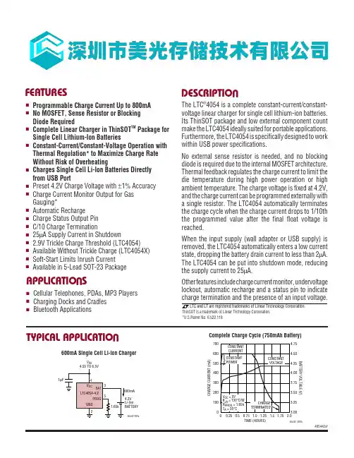
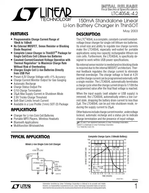
LTC4054-4.2/LTC4054X-4.2OPERATIOUThe LTC4054 is a single cell lithium-ion battery charger using a constant-current/constant-voltage algorithm. It can deliver up to 800mA of charge current (using a good thermal PCB layout) with a final float voltage accuracy of ±1%. The LTC4054 includes an internal P-channel power MOSFET and thermal regulation circuitry. No blocking diode or external current sense resistor is required; thus,the basic charger circuit requires only two external com-ponents. Furthermore, the LTC4054 is capable of operat-ing from a USB power source.Normal Charge CycleA charge cycle begins when the voltage at the V CC pin rises above the UVLO threshold level and a 1% program resistor is connected from the PROG pin to ground or when a battery is connected to the charger output. If the BAT pin is less than 2.9V, the charger enters trickle charge mode.In this mode, the LTC4054 supplies approximately 1/10the programmed charge current to bring the battery volt-age up to a safe level for full current charging. (Note: The LTC4054X does not include this trickle charge feature).When the BAT pin voltage rises above 2.9V, the charger enters constant-current mode, where the programmed charge current is supplied to the battery. When the BAT pin approaches the final float voltage (4.2V), the LTC4054enters constant-voltage mode and the charge current begins to decrease. When the charge current drops to 1/10 of the programmed value, the charge cycle ends.Programming Charge CurrentThe charge current is programmed using a single resistor from the PROG pin to ground. The battery charge current is 1000 times the current out of the PROG pin. The program resistor and the charge current are calculated using the following equations:R V I I VR PROG CHG CHG PROG==10001000,The charge current out of the BAT pin can be determinedat any time by monitoring the PROG pin voltage using the following equation:I V R BAT PROGPROG=•1000Charge TerminationA charge cycle is terminated when the charge current falls to 1/10th the programmed value after the final float voltage is reached. This condition is detected by using an internal,filtered comparator to monitor the PROG pin. When the PROG pin voltage falls below 100mV 1 for longer than t TERM (typically 1ms), charging is terminated. The charge current is latched off and the LTC4054 enters standby mode, where the input supply current drops to 200µA.(Note: C/10 termination is disabled in trickle charging and thermal limiting modes).When charging, transient loads on the BAT pin can cause the PROG pin to fall below 100mV for short periods of time before the DC charge current has dropped to 1/10th the programmed value. The 1ms filter time (t TERM ) on the termination comparator ensures that transient loads of this nature do not result in premature charge cycle termi-nation. Once the average charge current drops below 1/10th the programmed value, the LTC4054 terminates the charge cycle and ceases to provide any current through the BAT pin. In this state, all loads on the BAT pin must be supplied by the battery.The LTC4054 constantly monitors the BAT pin voltage in standby mode. If this voltage drops below the 4.05V recharge threshold (V RECHRG ), another charge cycle be-gins and current is once again supplied to the battery. To manually restart a charge cycle when in standby mode, the input voltage must be removed and reapplied, or the charger must be shut down and restarted using the PROG pin. Figure 1 shows the state diagram of a typical charge cycle.Charge Status Indicator (CHRG)The charge status output has three different states: strong pull-down (~10mA), weak pull-down (~20µA) and high impedance. The strong pull-down state indicates that the LTC4054 is in a charge cycle. Once the charge cycle has terminated, the pin state is determined by undervoltageNote 1: Any external sources that hold the PROG pin above 100mV will prevent the LTC4054from terminating a charge cycle.LTC4054-4.2/LTC4054X-4.2。
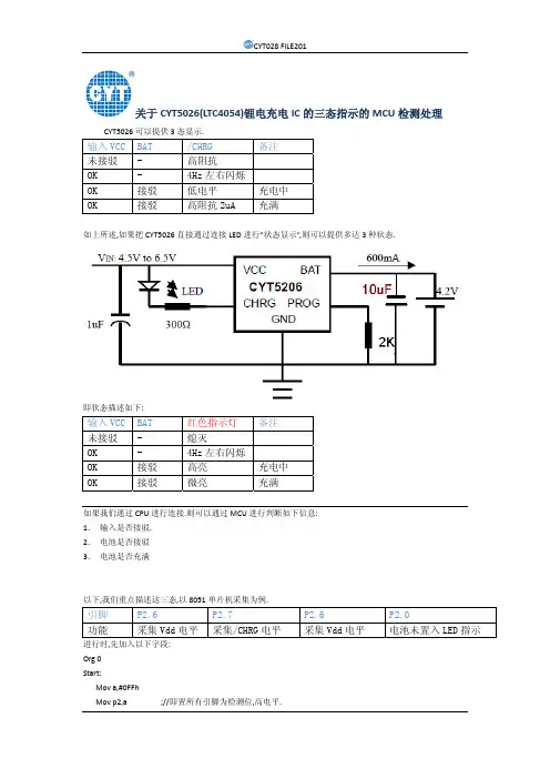
关于CYT5026(LTC4054)锂电充电IC的三态指示的MCU检测处理CYT5026可以提供3态显示.输入VCC BAT /CHRG 备注未接驳 - 高阻抗OK - 4Hz左右闪烁OK 接驳 低电平 充电中OK 接驳 高阻抗2uA 充满如上所述,如果把CYT5026直接通过连接LED进行”状态显示”,则可以提供多达3种状态.即状态描述如下:输入VCC BAT 红色指示灯 备注未接驳 - 熄灭OK - 4Hz左右闪烁OK 接驳 高亮 充电中OK 接驳 微亮 充满如果我们通过CPU进行连接.则可以通过MCU进行判断如下信息:1.输入是否接驳.2.电池是否接驳3.电池是否充满以下,我们重点描述这三态,以8051单片机采集为例.引脚 P2.6 P2.7 P2.6 P2.0功能 采集Vdd电平 采集/CHRG电平 采集Vdd电平 电池未置入LED指示 进行时,先加入以下字段:Org 0Start:Mov a,#0FFhMov p2,a ;//即置所有引脚为检测位,高电平.P2.6 P2.7 VBUS供电状态 电池状态- - 未接驳 -高 高 接驳 电池充满高 低 接驳 电池充电中高 高低跳转 接驳 电池未置入我们以下描述一段51汇编代码用以检测”电池未置入,VBUS供电正常”的状态.;//=============CYT5026(与LTC4054 pin2pin)的"电池未置入"状态的检测.================;//=======================深圳市长运通集成电路设计有限公司. FAE DEP.CYT028org 0start:mov a,#0ffhmov p2,adetect_battery_out1:jnb p2.6,vbus_error ;//一旦VBUS电平为低,则跳转至VBUS输入错误;一旦VBUS为高,则进行对P2.7的检测.jb p2.7,detect_battery_out1 ;//此处专门检测是否为"电池未置入",call delay5ms ;//当上一代码检测到p2.7为低电平,再延时5ms,来检测p2.7是否;//又跳转到了高电平,如果是,则认为在闪烁.jnb p2.7,bat_ok ;//如果p2.7不为高电平,则程序跳转到开始"bat ok",或"in charging" ;//一旦为高电平,即闪烁产生,即认为是"电池未置入",且进入下一程序,通过一个LED指示器进行表达.bat_out_display:clr p2.0 ;//通过点亮P2.0 LED,使其常亮,表明电池并未置入.jmp bat_out_displaydelay5ms: ;//延时5ms的延时模块.mov r6,#50d2:mov r7,#10djnz r7,$djnz r6,d2ret;//结束.End以下为具体电路原理图. 更多信息请浏览---------------------------------------------------------------------------深圳市长运通集成电路设计有限公司(ShenZhen CYT IC Design CO.,Ltd.)地址(Add):深圳市高新区中区科技中二路软件园4号楼2层西座电话(Tel):86-755-86169530传真(FAX):86-755-86168622网址(websit):专业内置恒流技术LED光源、可视化LED点彩技术、LED大屏恒流驱动技术、电源管理IC及整套解决方案提供商!。
Information furnished by Linear Technology Corporation is believed to be accurate and reliable. However, no responsibility is assumed for its use. Linear Technology Corporation makes no represen-tation that the interconnection of its circuits as described herein will not infringe on existing patent rights.12LTC4054L-4.24054l42i(Note 1)Input Supply Voltage (V CC )....................... –0.3V to 10V PROG............................................. –0.3V to V CC + 0.3V CHRG........................................................ –0.3V to 10V BAT............................................................. –0.3V to 7V BAT Short-Circuit Duration.......................... Continuous BAT Pin Current................................................. 200mA PROG Pin Current................................................1.5mA Maximum Junction Temperature..........................125°C Operating Temperature Range (Note 2)..–40°C to 85°C Storage Temperature Range.................–65°C to 125°C Lead Temperature (Soldering, 10 sec)..................300°CT JMAX = 125°C, θJA = 100°C/W TO 150°C/W DEPENDING ON PC BOARD LAYOUT (NOTE 4)ORDER PART NUMBER S5 PART MARKINGLTC4054LES5-4.2LTAFASYMBOL PARAMETER CONDITIONSMIN TYP MAX UNITSV CC Supply Voltage q 4.256.5V I CCSupply CurrentCharge Mode (Note 3), R PROG = 1k q 12002000µA Standby Mode (Charge Terminated)q 200500µA Shutdown Mode (R PROG Not Connected,q2550µA V CC < V BAT , or V CC < V UV )V FLOAT Regulated Output (Float) Voltage 0°C ≤ T A ≤ 85°C, I BAT = 40mA 4.158 4.2 4.242V I BATBAT Pin CurrentV CC = 5V, R PROG = 15k, Current Mode q 9.31010.7mA V CC = 5V, R PROG = 1k, Current Mode q 142.5150157.5mA Standby Mode, V BAT = 4.2Vq–2.5–6µA Shutdown Mode (R PROG Not Connected)±1±2µA Sleep Mode, V CC = 0V±1±2µA I TRIKL Trickle Charge Current V BAT < 2.9V, R PROG = 1k (I BAT = 150mA)q 51525mA V TRIKL Trickle Charge Threshold Voltage R PROG = 15k, V BAT Rising 2.8 2.93V V TRHYS Trickle Charge Hysteresis VoltageR PROG = 15k 6080110mV V UV V CC Undervoltage Lockout Threshold Voltage From V CC Low to High q 3.7 3.8 3.92V V UVHYS V CC Undervoltage Lockout Hysteresis Voltage q 150200300mV V MSD Manual Shutdown Threshold Voltage PROG Pin Rising q 1.15 1.21 1.30V PROG Pin Falling q 0.9 1.0 1.1V V ASD V CC – V BAT Lockout Threshold Voltage V CC from Low to High 70100140mV V CC from High to Low53050mV I TERM C/10 Termination Current Threshold R PROG = 15k (I BAT = 10mA) (Note 5)q 0.0850.100.115mA/mA R PROG = 1k (I BAT = 150mA) (Note 5)q 0.0880.100.112mA/mAV PROG PROG Pin VoltageR PROG = 1k, Current Mode q 0.931 1.07V I CHRG CHRG Pin Weak Pull-Down Current V CHRG = 5V 82035µA V CHRG CHRG Pin Output Low Voltage I CHRG = 5mA 0.350.6V ∆V RECHRGRecharge Battery Hysteresis VoltageV FLOAT – V RECHRG100150200mVThe q denotes specifications which apply over the full operatingtemperature range, otherwise specifications are at T A = 25°C. V CC = 5V, unless otherwise noted.ABSOLUTE AXI U RATI GSW W WU PACKAGE/ORDER I FOR ATIOU U WELECTRICAL CHARACTERISTICSConsult LTC Marketing for parts specified with wider operating temperature ranges.CHRG 1GND 2TOP VIEWS5 PACKAGE5-LEAD PLASTIC TSOT-23BAT 35 PROG4 V CC3LTC4054L-4.24054l42iU U UPI FU CTIO SThe q denotes specifications which apply over the full operatingtemperature range, otherwise specifications are at T A = 25°C. V CC = 5V, unless otherwise noted.ELECTRICAL CHARACTERISTICSCHRG (Pin 1): Open-Drain Charge Status Output. When the battery is charging, the CHRG pin is pulled low by an internal N-channel MOSFET. When the charge cycle is completed, a weak pull-down of approximately 20µA is connected to the CHRG pin, indicating an “AC present”condition. When the LTC4054L detects an undervoltage lockout condition, CHRG is forced to a high impedance state.GND (Pin 2): Ground.BAT (Pin 3): Charge Current Output. Provides charge current to the battery and regulates the final float voltage to 4.2V. An internal precision resistor divider from this pin sets this float voltage and is disconnected in shutdown mode.V CC (Pin 4): Positive Input Supply Voltage. Provides power to the charger. V CC can range from 4.25V to 6.5V and should be bypassed with at least a 1µF capacitor.When V CC drops to within 30mV of the BAT pin voltage, theLTC4054L enters shutdown mode, dropping I BAT to less than 2µA.PROG (Pin 5): Charge Current Program, Charge Current Monitor and Shutdown Pin. The charge current is pro-grammed by connecting a 1% resistor, R PROG , to ground.When charging in constant-current mode, this pin servos to 1V. In all modes, the voltage on this pin can be used to measure the charge current using the following formula:I BAT = (V PROG /R PROG ) • 150The PROG pin is also used to shut down the charger.Disconnecting the program resistor from ground allows a 3µA current to pull the PROG pin high. When it reaches the 1.21V shutdown threshold voltage, the charger enters shutdown mode, charging stops and the input supply current drops to 25µA. This pin is also clamped to approximately 2.4V. Driving this pin to voltages beyond the clamp voltage will draw currents as high as 1.5mA.Reconnecting R PROG to ground will return the charger to normal operation.SYMBOL PARAMETERCONDITIONSMINTYP MAXUNITST LIM Junction Temperature in Constant 120°C Temperature Mode R ON Power FET “ON” Resistance 1.5Ω(Between V CC and BAT)t SS Soft-Start TimeI BAT = 0 to I BAT =150V/R PROG 100µs t RECHARGE Recharge Comparator Filter Time V BAT High to Low 0.752 4.5ms t TERM Termination Comparator Filter Time I BAT Falling40010002500µs I PROGPROG Pin Pull-Up Current1.535µANote 1: Absolute Maximum Ratings are those values beyond which the life of the device may be impaired.Note 2: The LTC4054LE-4.2 is guaranteed to meet performance specifica-tions from 0°C to 70°C. Specifications over the –40°C to 85°C operating temperature range are assured by design, characterization and correlation with statistical process controls.Note 3: Supply current includes PROG pin current (≈1mA) but does not include any current delivered to the battery through the BAT pin.Note 4: See Thermal Considerations.Note 5: I TERM is expressed as a fraction of measured full charge current with indicated PROG resistor.LTC4054L-4.245LTC4054L-4.24054l42iOPERATIOU1Any external sources that hold the PROG pin above 100mV will prevent the LTC4054L fromterminating a charge cycle.The LTC4054L is a single cell lithium-ion battery charger using a constant-current/constant-voltage algorithm. Its ability to control charge currents as low as 10mA make it well-suited for charging low capacity lithium-ion coin cell batteries. The LTC4054L includes an internal P-channel power MOSFET and thermal regulation circuitry. No block-ing diode or external sense resistor is required; thus, the basic charger circuit requires only three external compo-nents. Furthermore, the LTC4054L is capable of operating from a USB power source.Normal Charge CycleThe charge cycle begins when the voltage at the V CC pin rises above the UVLO level and a 1% program resistor is connected from the PROG pin to ground. If the BAT pin is less than 2.9V, the charger enters trickle charge mode. In this mode, the LTC4054L supplies approximately 1/10 the programmed charge current in order to bring the battery voltage up to a safe level for full current charging.When the BAT pin voltage rises above 2.9V, the charger enters constant-current mode, where the programmed charge current is supplied to the battery. When the BAT pin approaches the final float voltage (4.2V), the LTC4054L enters constant-voltage mode and the charge current begins to decrease. When the charge current drops to 1/10 of the programmed value, the charge cycle ends.Programming Charge CurrentThe charge current is programmed using a single resistor from the PROG pin to ground. The battery charge current is 150 times the current out of the PROG pin. The program resistor and the charge current are calculated using the following equations:R V I I VR PROG CHG CHG PROG==150150,The charge current out of the BAT pin can be determinedat any time by monitoring the PROG pin voltage using the following equation:I V R BAT PROGPROG=•150Charge TerminationThe charge cycle is terminated when the charge current falls to 1/10th the programmed value. This condition is detected by using an internal, filtered comparator to monitor the PROG pin. When the PROG pin voltage falls below 100mV 1 for longer than t TERM (typically 1ms),charging is terminated. The charge current is latched off and the LTC4054L enters standby mode, where the input supply current drops to 200µA.While charging, transient loads on the BAT pin can cause the PROG pin to fall below 100mV for short periods of time, even before the DC charge current has dropped to 1/10th the programmed value. The 1ms filter time (t TERM )on the termination comparator ensures that transient loads of this nature do not result in premature charge cycle termination. Once the charge current drops below 1/10th the programmed value for longer than t TERM , the LTC4054L terminates the charge cycle and ceases to provide any current through the BAT pin. In this state, all loads on the BAT pin must be supplied by the battery.The LTC4054L constantly monitors the BAT pin voltage in standby mode. When this voltage drops below the 4.05V recharge threshold (V RECHRG ), another charge cycle be-gins and current is once again supplied to the battery. To manually restart a charge cycle when in standby mode, the input voltage must be removed and reapplied, or the charger must be shut down and restarted by momentarily floating the PROG pin. Figure 1 shows the state diagram of a typical charge cycle.Charge Status Indicator (CHRG)The charge status output has three different states: strong pull-down (~10mA), weak pull-down (~20uA), and high impedance. The strong pull-down state indicates that the LTC4054L is in a charge cycle. Once the charge cycle has terminated, the pin state is determined by undervoltage lockout conditions. A weak pull-down indicates that V CC meets the UVLO conditions and the LTC4054L is ready to charge. High impedance indicates that LTC4054L is in undervoltage lock-out mode: either V CC is within 100mV of the BAT pin voltage or insufficient voltage is applied to6LTC4054L-4.24054l42iOPERATIOUthe V CC pin. A microprocessor can be used to distinguish between these three states—this method is discussed in the Applications Information section.Thermal LimitingAn internal thermal feedback loop reduces the programmed charge current if the die temperature attempts to rise above a preset value of approximately 120°C. This feature protects the LTC4054L from excessive temperature and allows the user to push the limits of the power handling capability of a given circuit board without risk of damaging the LTC4054L. The charge current can be set according to typical (not worst-case) ambient temperature with the assurance that the charger will automatically reduce the current in worst-case conditions. ThinSOT power consid-erations are discussed further in the Applications Informa-tion section.Undervoltage Lockout (UVLO)An internal undervoltage lockout circuit monitors the input voltage and keeps the charger in shutdown mode until V CC rises above the undervoltage lockout threshold. The UVLO circuit has a built-in hysteresis of 200mV. Furthermore, to protect against reverse current in the power MOSFET, theUVLO circuit keeps the charger in shutdown mode if V CC falls to within 30mV of the battery voltage. If the UVLO comparator is tripped, the charger will not come out of shutdown mode until V CC rises 100mV above the battery voltage.Manual ShutdownAt any point in the charge cycle, the LTC4054L can be put into shutdown mode by removing R PROG thus floating the PROG pin. This reduces the battery drain current to less than 2µA and the supply current to less than 50µA. A new charge cycle can be initiated by reconnecting the program resistor.Automatic RechargeOnce the charge cycle is terminated, the LTC4054L con-tinuously monitors the voltage on the BAT pin. A charge cycle restarts when the battery voltage falls below 4.05V (which corresponds to approximately 80% to 90% battery capacity). This ensures that the battery is kept at or near a fully charged condition and eliminates the need for periodic charge cycle initiations. CHRG output enters a strong pull-down state during recharge cycles.7LTC4054L-4.289LTC4054L-4.24054l42iAPPLICATIO S I FOR ATIOW UUU Power DissipationThe conditions that cause the LTC4054L to reduce charge current through thermal feedback can be approximated by considering the power dissipated in the IC. Nearly all of this power dissipation is generated from the internal MOSFET—this is calculated to be approximately:P D = (V CC – V BAT ) • I BATwhere P D is the power dissipated, V CC is the input supply voltage, V BAT is the battery voltage and I BAT is the charge current. The approximate ambient temperature at which the thermal feedback begins to protect the IC is:T A = 120°C – P D θJAT A = 120°C – (V CC – V BAT ) • I BAT • θJAExample: An LTC4054L operating from a 6V wall adapter is programmed to supply 150mA full-scale current to a discharged Li-Ion battery with a voltage of 3.75V. Assum-ing θJA is 200°C/W, the ambient temperature at which the LTC4054L will begin to reduce the charge current is approximately:T A = 120°C – (6V – 3.75V) • (150mA) • 200°C/W T A = 120°C – 0.3375W • 200°C/W = 120°C – 67.5°C T A = 52.5°CThe LTC4054L can be used above 52.5°C, but the charge current will be reduced from 150mA. The approximate current at a given ambient temperature can be approxi-mated by:I C T V V BAT A CC BAT JA=°()120––•θUsing the previous example with an ambient tempera-ture of 60°C, the charge current will be reduced to approximately:I C C V V C W CC AI mABAT BAT =°°()°=°°=12060637520060450133––.•//Moreover, when thermal feedback reduces the charge current, the voltage at the PROG pin is also reduced proportionally as discussed in the Operation section.It is important to remember that LTC4054L applications do not need to be designed for worst-case thermal condi-tions since the IC will automatically reduce power dissipa-tion when the junction temperature reaches approximately 120°C.Thermal ConsiderationsBecause of the small size of the ThinSOT package, it is very important to use a good thermal PC board layout to maximize the available charge current. The thermal path for the heat generated by the IC is from the die to the copper lead frame, through the package leads, (especially the ground lead) to the PC board copper. The PC board copper is the heat sink. The footprint copper pads should be as wide as possible and expand out to larger copper areas to spread and dissipate the heat to the surrounding ambient. Feedthrough vias to inner or backside copper layers are also useful in improving the overall thermal performance of the charger. Other heat sources on the board, not related to the charger, must also be considered when designing a PC board layout because they will affect overall temperature rise and the maximum charge current.LTC4054L-4.2101112LTC4054L-4.2LT/TP 0503 1K • PRINTED IN USA© LINEAR TECHNOLOGY CORPORA TION 20031630 McCarthy Blvd., Milpitas, CA 95035-7417(408) 432-1900 q FAX: (408) 434-0507 q 。
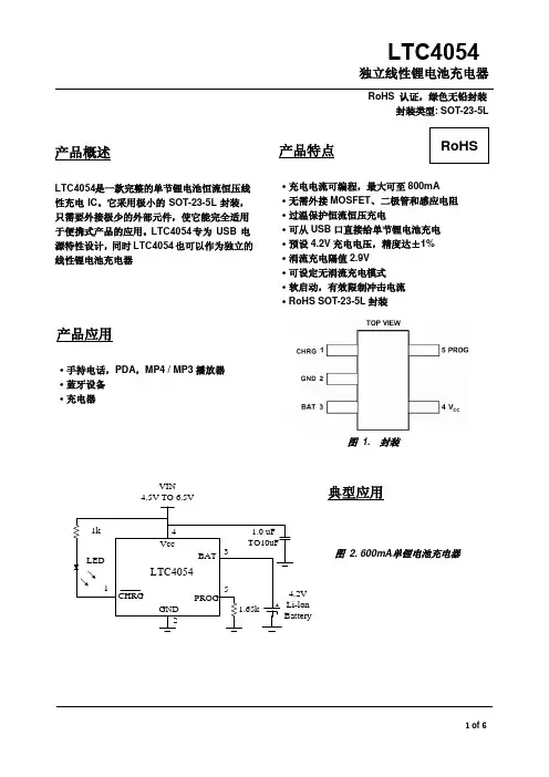
4054产品规格书拟稿审核批准TP4054 线性锂离子电池充电器描述TP4054是一款完整的单节锂离子电池采用恒定电流/恒定电压线性充电器。
其SOT 封装与较少的外部元件数目使得4054成为便携式应用的理想选择。
4054可以适合USB 电源和适配器电源工作。
由于采用了内部PMOSFET 架构,加上防倒充电路,所以不需要外部检测电阻器和隔离二极管。
热反馈可对充电电流进行调节,以便在大功率操作或高环境温度条件下对芯片温度加以限制。
充电电压固定于4.2V ,而充电电流可通过一个电阻器进行外部设置。
当充电电流在达到最终浮充电压之后降至设定值1/10时,4054将自动终止充电循环。
当输入电压(交流适配器或USB 电源)被拿掉时,4054自动进入一个低电流状态,将电池漏电流降至2uA 以下。
也可将4054置于停机模式,以而将供电电流降至45uA 。
4054的其他特点包括充电电流监控器、欠压闭锁、自动再充电和一个用于指示充电结束和输入电压接入的状态引脚。
特点 ·高达800mA 的可编程充电电流; ·无需MOSFET、检测电阻器或隔离二极管;·用于单节锂离子电池、采用SOT23-5封装的完整线性充电器;·恒定电流/恒定电压操作,并具有可在无过热危险的情况下实现充电速率最大化的热调节功能;·直接从USB 端口给单节锂离子电池充电; ·精度达到±1%的4.2V 预设充电电压; ·用于电池电量检测的充电电流监控器输出; ·自动再充电;·充电状态输出引脚; ·C/10充电终止;·待机模式下的供电电流为45uA; ·2.9V涓流充电器件版本; ·软启动限制了浪涌电流; ·采用5引脚SOT-23封装。
应用 ·蜂窝电话、PDA、MP3播放器; ·充电座; ·蓝牙应用。
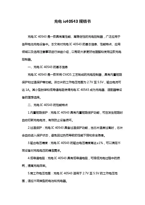
充电ic40543规格书充电IC 40543是一款具有高性能、高稳定性的充电控制器,广泛应用于各种电池充电设备中。
本文将对充电IC 40543的基本信息、性能特点、应用领域以及选用注意事项进行详细介绍,以帮助大家更好地理解和使用这款充电控制器。
一、充电IC 40543的基本信息充电IC 40543是一款采用CMOS工艺制成的充电控制器,具有内置短路保护和过温保护等功能。
该芯片的工作电压范围为2.7V至5.5V,输出电流可达1A。
其小型封装和低导通电阻使得充电IC 40543成为充电器、适配器等设备的理想选择。
二、充电IC 40543的性能特点1.内置短路保护:充电IC 40543具有内置短路保护功能,可在发生短路时自动切断充电电流,有效防止设备损坏。
2.过温保护:充电IC 40543具备过温保护功能,当芯片温度过高时,芯片会自动进入保护状态,避免因过热而导致的性能下降和安全隐患。
3.输出电压精度:充电IC 40543的输出电压精度高达±1%,可以满足不同设备对充电电压的精准需求。
4.低导通电阻:充电IC 40543具有低导通电阻,可降低充电过程中的损耗,提高充电效率。
5.宽工作电压范围:充电IC 40543适用于2.7V至5.5V的工作电压范围,适应不同类型的电池和充电器。
三、充电IC 40543的应用领域充电IC 40543适用于各种电池充电设备,如充电器、适配器、充电宝、电动工具、太阳能充电系统等。
此外,还可应用于智能家居、物联网、医疗设备等领域,满足各种充电需求。
四、充电IC 40543的选用注意事项1.根据设备电池类型和充电需求,选择合适的充电IC 40543型号。
不同型号的充电IC 40543具有不同的性能参数,需根据实际应用场景进行选择。
2.在选用充电IC 40543时,应注意其工作电压、输出电流等参数,确保与设备兼容。
3.考虑充电IC 40543的封装形式和尺寸,确保易于安装和布局。
4054产品规格书拟稿审核批准TP4054 线性锂离子电池充电器描述TP4054是一款完整的单节锂离子电池采用恒定电流/恒定电压线性充电器。
其SOT 封装与较少的外部元件数目使得4054成为便携式应用的理想选择。
4054可以适合USB 电源和适配器电源工作。
由于采用了内部PMOSFET 架构,加上防倒充电路,所以不需要外部检测电阻器和隔离二极管。
热反馈可对充电电流进行调节,以便在大功率操作或高环境温度条件下对芯片温度加以限制。
充电电压固定于4.2V ,而充电电流可通过一个电阻器进行外部设置。
当充电电流在达到最终浮充电压之后降至设定值1/10时,4054将自动终止充电循环。
当输入电压(交流适配器或USB 电源)被拿掉时,4054自动进入一个低电流状态,将电池漏电流降至2uA 以下。
也可将4054置于停机模式,以而将供电电流降至45uA 。
4054的其他特点包括充电电流监控器、欠压闭锁、自动再充电和一个用于指示充电结束和输入电压接入的状态引脚。
特点 ·高达800mA 的可编程充电电流; ·无需MOSFET、检测电阻器或隔离二极管;·用于单节锂离子电池、采用SOT23-5封装的完整线性充电器;·恒定电流/恒定电压操作,并具有可在无过热危险的情况下实现充电速率最大化的热调节功能;·直接从USB 端口给单节锂离子电池充电; ·精度达到±1%的4.2V 预设充电电压; ·用于电池电量检测的充电电流监控器输出; ·自动再充电;·充电状态输出引脚; ·C/10充电终止;·待机模式下的供电电流为45uA; ·2.9V涓流充电器件版本; ·软启动限制了浪涌电流; ·采用5引脚SOT-23封装。
应用 ·蜂窝电话、PDA、MP3播放器; ·充电座; ·蓝牙应用。
LTC4054丝印LTH7锂电充电管理IC————————————————————————————————作者:————————————————————————————————日期:2V1.31)典型应用电路注:R1 电阻建议不要省列与 C 1 构成 R C 滤波防止过充电压。
如果 R 1 电阻不接 C 1 使用 10UF 以上电容。
典型运用电路仅供参考,其它以实际运用为准。
概述HX4054A 是一款单节锂离子电池恒流/恒压线性充电器,简单的外部应用电路非常适合便携式设备应用,适合 USB 电源和适配器电源工作,内部采用防倒充电路,不需要外部隔离二极管。
热反馈可对充电电流进行自动调节,以便在大功率操作或高环境温度条件下对芯片温度加以限制。
HX4054A 充电截止电压为 4.2V, 充电电流可通过外部电阻 进行设置。
当充电电流降至设定值的 1/10 时,HX4054A 将自动结束充电过程。
当输入电压被移掉后,HX4054A 自动进入低电流待机状态,将待机电流降至 1uA 以下。
HX4054A 在有输入电源时也可置于停机模式,从而将工作电流降至 30uA 。
兼容TP4054 XT4054 LN2054 SE9016 ME4054 XT4052 EUP8054 AS3020 XZ3085A BL8572 HX6001 QX4054 HYM4054 SUN4054 FK5406 AP5056 SLM4054 LP4054 APL3202 OPC8020 OHL5100 LM2054 UCT3054 TQ7051 特点∙ 锂电池正负极反接保护(没充电的情况下 ∙ 最大充电电流:500mA∙ 无需 MOSFET 、检测电阻器和隔离二极管 ∙ 智能热调节功能可实现充电速率最大化 ∙ 智能再充电功能 ∙ 预充电压:4.2V±1% ∙ 3C/10 充电终止 ∙ 待机电流 30uA∙ BAT 超低自耗电 1uA ∙ 2.9V 涓流充电阈值∙ 单独的充电、结束指示灯控制信号 ∙封装形式:SOT23-5应用∙ 手机、PDA 、MP3/MP4 ∙ 蓝牙耳机、GPS ∙ 充电座∙数码相机、Mini 音响等便携式设备V1.32管脚定购信息SOT23-5L封装 定购型号 包装形式产品正印SOT23-5LHX4054A极限参数(注 1)符号 参数额定值 单位 VCC 输入电源电压 -0.3~7 V PROG PROG 脚电压 -0.3~0.3 V BAT BAT 脚电压 -0.3~7 V CHRG CHRG 脚电压-0.3~7 V T BAT_SHTBAT 脚短路持续时间 连续 - I BAT BAT 脚电流 600 mA I PROG PROG 脚电流 600 uA T OP 工作环境温度 -40~85 ℃ T STG储存温度 -65~125 ℃ ESDHBM2000 V MM200V注 1:最大极限值是指超出该工作范围芯片可能会损坏。
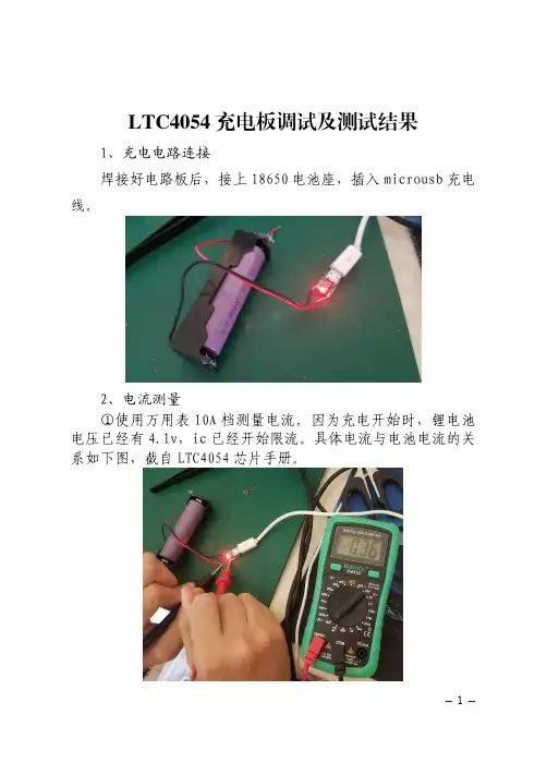
1LTC4054充电板调试及测试结果
1、充电电路连接
焊接好电路板后,接上18650电池座,插入microusb 充电
线。
2、电流测量
①使用万用表10A 档测量电流。
因为充电开始时,锂电池电压已经有4.1v,ic 已经开始限流。
具体电流与电池电流的关系如下图,截自LTC4054
芯片手册。
2
②使用usb
电流计测量电流
3、充电完成
Led 灯熄灭
3
电池电压为
4.21V
4、结论
以LTC4054为主芯片制作的充电电路板具有体积小、成本低的特点。
充电性能符合预期,能满足一般要求的充电情况。
5、缺点
因该IC 为线性锂电池充电,充电电流较大时芯片温度高,
温度高会导致芯片寿命减少且充电电流变小。
6、改进空间
①增加散热片。
②芯片电源输入端串联一个电阻或者二极管降低芯片上的压差。
可以串联一个1/8W的0.25Ω的电阻,或一个整流二极管如1N4001。
4。
小型150mA铿电池充电控制器LTC4054
类别:电源技术阅读:1102 LTCA054是凌特公司生产的ThinSOT封装150 mA锉电池充电器。
(1)特性
LTC1054的充电电流从10一150 mA可编程,
不需要外接MOSFET、传感电阻或阻塞二
极管,采用恒流/恒压工作模式,能直接从USB口对.
为土1%,充电电流准确度在10 mA电流条件下达到
预置电压为4.2V,精度
7%,而在150 mA电流条件下为5%。
(2)内部电路与引脚功能
LTC4054采用SOT-23封装,
具有充电电流监测、欠压闭锁和状态显示引脚。
其内部电路
框图如图所示,各引脚功能见表
(3)应用电路
LTC4054也是一款独立型充电器,操作无须使用微处理器,适用于钮扣型可再充电锉电
池等低电流充电电路中,如MP3播放器、无线手持设备、蓝牙设备和多功能手表等。
LTC4054的典型应用电路如图所示。
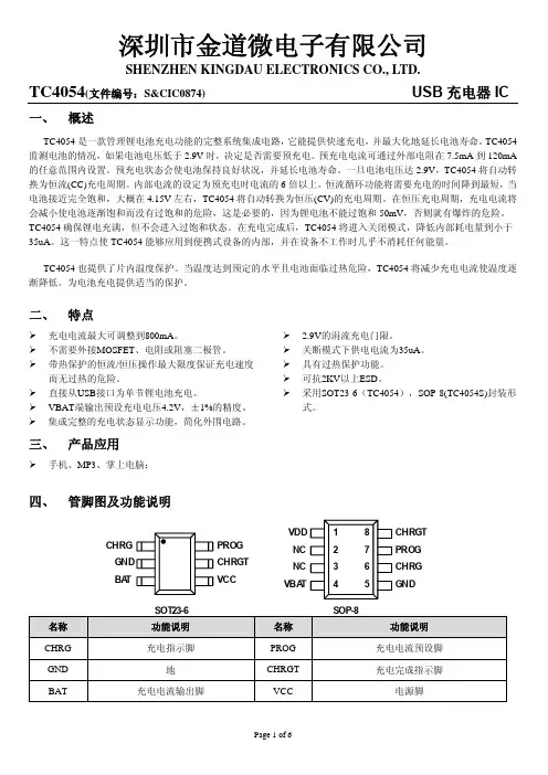
TC4054(文件编号:S&CIC1076)0.5A线性锂离子电池充电器IC一、概述TC4054是恒流/恒压座充充电器芯片,主要应用于单节锂电池充电。
无需外接检测电阻,其内部为MOSFET 结构,因此无需外接反向二极管。
TC4054在大功率和高环境温度下可以调节充电电流以限制芯片温度。
它的充电电压固定在4.2V,充电电流可以通过外置一个电阻器进行调节。
当达到浮充电压并且充电电流下降到设定电路的1/10时,TC4054自动终止充电过程。
当输入电压移开之后,TC4054自动进入低电流模式,从电池吸取少于2uA的电流。
当TC4054进入待机模式时,供电电流小于25uA。
TC4054还可以监控充电电流,具有电压检测、自动循环充电的特性,并且具有一个指示管脚指示充电终止状态和输入电压状态。
二、特性可达500mA的可编程充电电流无需外接MOSFET、检测电阻、反向二极管恒流/恒压模式操作,具有热保护功能可通过USB端口为锂电池充电具有1%精度的预设充电电压待机模式下电流为20uA2.9V涓流充电电压软启动限制了浪涌电流采用SOT23-5封装TC4054(文件编号:S&CIC1076)0.5A线性锂离子电池充电器ICTC4054(文件编号:S&CIC1076)0.5A线性锂离子电池充电器IC 七、电气特性(V=5V;T J=25℃,除非另有说明)IN注:1、超出最大工作范围可能会损坏芯片。
2、超出器件工作参数极限,不保证其正常功能。
3、电源电流包括PROG端电流(大约100uA),不包括通过BAT端传输到电池的其他电流(大约100uA)。
4、充电终止电流一般是设定充电电流的0.1倍。
TC4054(文件编号:S&CIC1076)0.5A线性锂离子电池充电器IC八、波形图浮动电压VS电源电压充电电流VS 电源电压涓流充电电流VS电源电压浮动电压VS 温度TC4054(文件编号:S&CIC1076)0.5A线性锂离子电池充电器IC九、封装尺寸图SOT23-5。
USB接口锂电池充电简介锂电池充电中的细节安全的锂电池充电过程我们可以购买到的正规移动电源/电池,大都使用了锂电池,手机、平板、mp3、相机里面也都有锂电池。
准确来说是“锂电池电芯+充/放电控制电路”,因为锂电池电芯很脆弱,过低电压下放电、过高电压下充电都会永久损坏电芯。
比如充电电压4.2V,如果采用4.25V充电,电芯必坏无疑。
鉴于锂电池如此敏感,大部分充电电路都直接使用现成的芯片控制锂电池充放电过程。
充电的过程是这样:1、涓流充电阶段先判断电池电压,如果电压低于最低电压则首先进行涓流充电。
如果一开始电压就高于最低电压则直接进入第二个阶段:恒流充电。
最低电压根据电芯不同有不同的设定,基本都在2.5V-3.0V之间。
涓流就是小电流的意思,多小的电流算小呢?0.06C-0.1C就算涓流。
C是什么?举例来说2000mAH的电池1C就是2000mA;5000mAH的电池1C就是5000mA。
(大部分锂电池充电和放电都可以达到1C);对于这块电池来说0.1C就是188mA2、恒流充电阶段涓流充电到电池电压高于最小电压后,充电器以恒定电流给电池充电,这个恒定电流就是很多充电器上标注的多少多少安。
比如iPhone4/4S是1A,iPad是2.1A。
恒流充电的过程中,电池电压也在逐渐升高,从最小电压上升到4.2V时恒流充电阶段终止,恒流过程实际能为电池充进40%-70%左右的电量。
之后进入下一个阶段:恒压充电。
3、恒压充电阶段恒定4.2V(±0.35%的精度)给电池充电,这个阶段里电流就不能维持恒定了,而是逐渐下降,当充电电流下降至0.1C后充电过程结束。
这个阶段实际上可以充进60%-30%的电量。
所以一块2000mAH的电池用1000mA的充电器充电时即便没有热损失出现,时间也会大于2小时。
如果把电压转换中产生的废热算上也许实际充满电的时间超过3小时。
上图就是刚才所说的3个过程,所有锂电池充电时都要遵循这个规律,所以现在转而说到USB口给锂电池充电,中间就需要有控制电路和电压转换电路,不然4.5V-5V的电压加在锂电池上,电池直接就损坏了。
典型应用电路图V CC图1:QX4054典型应用电路图概述 QX4054 是一款完整的单节锂离子电池恒流恒压线性充电控制器,只需要极少的外接元件,便能适用于便携式产品的应用,而且QX4054 是专门为USB 电源充电而设计的 QX4054根据电池电压的不同可分别有涓流充电,恒流充电和恒压充电等三种充电模式。
涓流充电模式的充电电流为满充电电流的1/10;恒流充电模式的充电电流为满充电电流;恒压充电模式的充电电压被固定在4.2V ,在电池电压达到满电量电压并且充电电流降至满充电电流的1/10时,QX4054将自动停止充电。
满充电电流是通过一个外接电阻来设定的。
QX4054还内置了睡眠模式、关断模式、充电电流监测、低压关断、过温保护、自动再充电、工作状态指示等功能。
QX4054采用SOT-23-5封装。
特点 电源电压:4.25 V~6.0V 可编程充电电流:最高800mA 预设4.2V 充电电压的精度:±1% 关断模式下的支持电流:25uA涓流充电阈值电压:2.9V过热保护:保证快速而安全的充电 软启动:有效限制冲击电流无需外接MOS 管、感应电阻和二极管 可从USB 口直接给电池充电 应用领域移动电话、PDA 等便携式设备 锂离子电池充电器 蓝牙设备订货信息产品型号QX4054封装及管脚分配PROG VCC54132GNDCHRG BATSOT-23-5管脚定义内部电路方框图VCC CHRGBAT PROG图2:QX4054的内部电路方框图极限参数(注1)注1:超过上表中规定的极限参数会导致器件永久性损坏,而工作在以上极限条件下可能会影响器件的可靠性。
电特性除非特别说明,V CC =5V ,T A =25o C电特性(接上一页)除非特别说明,V CC=5V,T A =25o C电特性(接上一页)除非特别说明,V CC=5V,T A =25ºC注2:支持电流包括PROG 脚电流(近似100µA),但不包括通过BA T脚流到电池的电流(近似100mA). 注3:I TER M是PROG脚电阻设定充电电流值的一部分。
124054l42f(Note 1)Input Supply Voltage (V CC )....................... –0.3V to 10V PROG............................................. –0.3V to V CC + 0.3V CHRG........................................................ –0.3V to 10V BAT............................................................. –0.3V to 7V BAT Short-Circuit Duration.......................... Continuous BAT Pin Current................................................. 200mA PROG Pin Current................................................1.5mA Maximum Junction Temperature..........................125°C Operating Temperature Range (Note 2)..–40°C to 85°C Storage Temperature Range.................–65°C to 125°C Lead Temperature (Soldering, 10 sec)..................300°CT JMAX = 125°C, θJA = 80°C/W TO 150°C/W DEPENDING ON PC BOARD LAYOUT (NOTE 3)ORDER PART NUMBER S5 PART MARKINGLTC4054LES5-4.2LTAFASYMBOL PARAMETER CONDITIONSMIN TYP MAX UNITSV CC Supply Voltage q 4.256.5V I CCSupply CurrentCharge Mode (Note 4), R PROG = 1k q 12002000µA Standby Mode (Charge Terminated)q 200500µA Shutdown Mode (R PROG Not Connected,q2550µA V CC < V BAT , or V CC < V UV )V FLOAT Regulated Output (Float) Voltage 0°C ≤ T A ≤ 85°C, I BAT = 40mA 4.158 4.2 4.242V I BATBAT Pin CurrentR PROG = 15k, Current Mode q 9.31010.7mA R PROG = 1k, Current Mode q 142.5150157.5mA Standby Mode, V BAT = 4.2Vq–2.5–6µA Shutdown Mode (R PROG Not Connected)±1±2µA Sleep Mode, V CC = 0V ±1±2µA I TRIKL Trickle Charge Current V BAT < V TRIKL , R PROG = 1k (I BAT = 150mA)q51525mA V TRIKL Trickle Charge Threshold Voltage R PROG = 15k, V BAT Rising 2.8 2.93V V TRHYS Trickle Charge Hysteresis VoltageR PROG = 15k 6080110mV V UV V CC Undervoltage Lockout Threshold Voltage From V CC Low to High q 3.7 3.8 3.92V V UVHYS V CC Undervoltage Lockout Hysteresis Voltage q 150200300mV V MSD Manual Shutdown Threshold Voltage PROG Pin Rising q 1.15 1.21 1.30V PROG Pin Falling q 0.9 1.0 1.1V V ASD V CC – V BAT Lockout Threshold Voltage V CC from Low to High 70100140mV V CC from High to Low53050mV I TERM C/10 Termination Current Threshold R PROG = 15k (I BAT = 10mA) (Note 5)q 0.0850.100.115mA/mA R PROG = 1k (I BAT = 150mA) (Note 5)q 0.0880.100.112mA/mAV PROG PROG Pin VoltageR PROG = 1k, Current Mode q 0.931 1.07V I CHRG CHRG Pin Weak Pull-Down Current V CHRG = 5V 82035µA V CHRG CHRG Pin Output Low Voltage I CHRG = 5mA 0.350.6V ∆V RECHRGRecharge Battery Hysteresis VoltageV FLOAT – V RECHRG100150200mVThe q denotes specifications which apply over the full operatingtemperature range, otherwise specifications are at T A = 25°C. V CC = 5V, unless otherwise noted.ABSOLUTE AXI U RATI GSW W WU PACKAGE/ORDER I FOR ATIOU U WELECTRICAL CHARACTERISTICSConsult LTC Marketing for parts specified with wider operating temperature ranges.CHRG 1GND 2TOP VIEWS5 PACKAGE5-LEAD PLASTIC TSOT-23BAT 35 PROG4 V CC345UUUPI FU CTIO SCHRG (Pin 1): Open-Drain Charge Status Output. When the battery is charging, the CHRG pin is pulled low by an internal N-channel MOSFET. When the charge cycle is completed, a weak pull-down of approximately 20µA is connected to the CHRG pin, indicating an “AC present”condition. When the LTC4054L detects an undervoltage lockout condition, CHRG is forced high impedance. GND (Pin 2): Ground.BAT (Pin 3): Charge Current Output. Provides charge current to the battery and regulates the final float voltage to 4.2V. An internal precision resistor divider from this pin sets this float voltage and is disconnected in shutdown mode.V CC (Pin 4): Positive Input Supply Voltage. Provides power to the charger. V CC can range from 4.25V to 6.5V and should be bypassed with at least a 1µF capacitor. When V CC drops to within 30mV of the BAT pin voltage, the LTC4054L enters shutdown mode, dropping I BAT to less than 2µA.PROG (Pin 5): Charge Current Program, Charge Current Monitor and Shutdown Pin. The charge current is pro-grammed by connecting a 1% resistor, R PROG, to ground. When charging in constant-current mode, this pin servos to 1V. In all modes, the voltage on this pin can be used to measure the charge current using the following formula: I BAT = (V PROG/R PROG) • 150The PROG pin is also used to shut down the charger. Disconnecting the program resistor from ground allows a 3µA current to pull the PROG pin high. When it reaches the 1.21V shutdown threshold voltage, the charger enters shutdown mode, charging stops and the input supply current drops to 25µA. This pin is also clamped to approximately 2.4V. Driving this pin to voltages beyond the clamp voltage will draw currents as high as 1.5mA. Reconnecting R PROG to ground will return the charger to normal operation.64054l42f784054l42fOPERATIO1Any external sources that hold the PROG pin above 100mV will prevent the LTC4054L fromterminating a charge cycle.The LTC4054L is a single cell lithium-ion battery charger using a constant-current/constant-voltage algorithm. Its ability to control charge currents as low as 10mA make it well-suited for charging low capacity lithium-ion coin cell batteries. The LTC4054L includes an internal P-channel power MOSFET and thermal regulation circuitry. No block-ing diode or external sense resistor is required; thus, the basic charger circuit requires only three external compo-nents. Furthermore, the LTC4054L is capable of operating from a USB power source.Normal Charge CycleThe charge cycle begins when the voltage at the V CC pin rises above the UVLO level and a 1% program resistor is connected from the PROG pin to ground. If the BAT pin is less than 2.9V, the charger enters trickle charge mode. In this mode, the LTC4054L supplies approximately 1/10 the programmed charge current in order to bring the battery voltage up to a safe level for full current charging.When the BAT pin voltage rises above 2.9V, the charger enters constant-current mode, where the programmed charge current is supplied to the battery. When the BAT pin approaches the final float voltage (4.2V), the LTC4054L enters constant-voltage mode and the charge current begins to decrease. When the charge current drops to 1/10 of the programmed value, the charge cycle ends.Programming Charge CurrentThe charge current is programmed using a single resistor from the PROG pin to ground. The battery charge current is 150 times the current out of the PROG pin. The program resistor and the charge current are calculated using the following equations:R V I I VR PROG CHG CHG PROG==150150,The charge current out of the BAT pin can be determined at any time by monitoring the PROG pin voltage using the following equation:I V R BAT PROGPROG=•150Charge TerminationThe charge cycle is terminated when the charge current falls to 1/10th the programmed value after the final float voltage is reached. This condition is detected by using an internal, filtered comparator to monitor the PROG pin.When the PROG pin voltage falls below 100mV 1 for longer than t TERM (typically 1ms), charging is terminated. The charge current is latched off and the LTC4054L enters standby mode, where the input supply current drops to 200µA. (Note: C/10 termination is disabled in trickle charg-ing and thermal limiting modes.)While charging, transient loads on the BAT pin can cause the PROG pin to fall below 100mV for short periods of time before the DC charge current has dropped to 1/10th the programmed value. The 1ms filter time (t TERM ) on the termination comparator ensures that transient loads of this nature do not result in premature charge cycle termi-nation. Once the average charge current drops below 1/10th the programmed value for longer than t TERM , the LTC4054L terminates the charge cycle and ceases to provide any current through the BAT pin. In this state, all loads on the BAT pin must be supplied by the battery.The LTC4054L constantly monitors the BAT pin voltage in standby mode. If this voltage drops below the 4.05V recharge threshold (V RECHRG ), another charge cycle be-gins and current is once again supplied to the battery. To manually restart a charge cycle when in standby mode, the input voltage must be removed and reapplied, or the charger must be shut down and restarted using the PROG pin. Figure 1 shows the state diagram of a typical charge cycle.9OPERATIOManual ShutdownAt any point in the charge cycle, the LTC4054L can be put into shutdown mode by removing R PROG thus floating the PROG pin. This reduces the battery drain current to less than 2µA and the supply current to less than 50µA. A new charge cycle can be initiated by reconnecting the program resistor.In manual shutdown, the CHRG pin is in a weak pull-down state as long as V CC is high enough to exceed the UVLO conditions. The CHRG pin is in a high impedance state if the LTC4054L is in undervoltage lockout mode: either V CC is within 100mV of the BAT pin voltage or insufficient voltage is applied to the V CC pin.Automatic RechargeOnce the charge cycle is terminated, the LTC4054L con-tinuously monitors the voltage on the BAT pin using a comparator with a 2ms filter time (t RECHARGE). A charge cycle restarts when the battery voltage falls below 4.05V (which corresponds to approximately 80% to 90% battery capacity). This ensures that the battery is kept at or near a fully charged condition and eliminates the need for periodic charge cycle initiations. CHRG output enters a strong pull-down state during recharge cycles.104054l42f11124054l42fAPPLICATIO S I FOR ATIOW UUU Example: An LTC4054L operating from a 6V wall adapter is programmed to supply 150mA full-scale current to a discharged Li-Ion battery with a voltage of 3.75V. Assum-ing θJA is 200°C/W, the ambient temperature at which the LTC4054L will begin to reduce the charge current is approximately:T A = 120°C – (6V – 3.75V) • (150mA) • 200°C/W T A = 120°C – 0.3375W • 200°C/W = 120°C – 67.5°C T A = 52.5°CThe LTC4054L can be used above 52.5°C, but the charge current will be reduced from 150mA. The approximate current at a given ambient temperature can be approxi-mated by:I C T V V BAT A CC BAT JA=°()120––•θUsing the previous example with an ambient tempera-ture of 60°C, the charge current will be reduced to approximately:I C C V V C W C C AI mABATBAT =°°()°=°°=12060637520060450133––.•//Moreover, when thermal feedback reduces the charge current, the voltage at the PROG pin is also reduced proportionally as discussed in the Operation section.It is important to remember that LTC4054L applications do not need to be designed for worst-case thermal condi-tions since the IC will automatically reduce power dissipa-tion when the junction temperature reaches approximately 120°C.Thermal ConsiderationsBecause of the small size of the ThinSOT package, it is very important to use a good thermal PC board layout to maximize the available charge current. The thermal path for the heat generated by the IC is from the die to the copper lead frame, through the package leads, (especially the ground lead) to the PC board copper. The PC board copper is the heat sink. The footprint copper pads should be as wide as possible and expand out to larger copper areas to spread and dissipate the heat to the surrounding ambient. Feedthrough vias to inner or backside copper layers are also useful in improving the overall thermal performance of the charger. Other heat sources on the board, not related to the charger, must also be considered when designing a PC board layout because they will affect overall temperature rise and the maximum charge current.The following table lists thermal resistance for several different board sizes and copper areas. All measurements were taken in still air on 3/32" FR-4 board with the device mounted on topside.Table 1. Measured Thermal Resistance (2-Layer Board*)COPPER AREA BOARDTHERMAL RESISTANCE TOPSIDE BACKSIDE AREA JUNCTION-TO-AMBIENT2500mm 22500mm 22500mm 2125°C/W 1000mm 22500mm 22500mm 2125°C/W 225mm 22500mm 22500mm 2130°C/W 100mm 22500mm 22500mm 2135°C/W 50mm 22500mm 22500mm 2150°C/W*Each layer uses one ounce copperTable 2. Measured Thermal Resistance (4-Layer Board**)COPPER AREA BOARD THERMAL RESISTANCE (EACH SIDE)AREA JUNCTION-TO-AMBIENT2500mm 2***2500mm 280°C/W**Top and bottom layers use two ounce copper, inner layers use one ounce copper.***10,000mm 2 total copper area13141516LT/TP 1203 1K • PRINTED IN USA© LINEAR TECHNOLOGY CORPORA TION 20031630 McCarthy Blvd., Milpitas, CA 95035-7417(408) 432-1900 q FAX: (408) 434-0507 q 。
ltc4054充电保护电路详解
LTC4054简介LTC4054是凌特公司的锂电池充电芯片,它是专为单节锂电池充电需要设计的单片集成芯片。
用LTC4054设计的充电器只需几个元件,非常简洁。
LTCA054在工作中无须专门的散热器,就可对电池进行大电流的充电,而且可以从USB 端口取电工作,非常适合用于电脑的周边设备中,如MP3、PDA掌上电脑、数码录音笔等。
LTC4054充电保护电路工作流程TC4054是运用恒流/恒压充电算法的单节锂电池充电器,它提供高达800mA充电电流(使用较好散热的PCB板),最后充电电压精度达1%。
LTCA054内置P沟道MOSFET功率管和温度调节电路,无须隔离二极管和外接电流传感电阻,因此基本的充电器电路仅需3个外围元件。
此外,LTC4054还能从USB端口取电工作。
普通充电周期
充电周期开始于当Vcc电源超过UVLO限定的电压和一个1%精度的电阻接在PROG和GND之间。
如果BAT引脚的电压低于2.9V,充电器进入涓流充电模式,在此模式LTCA-054用大约充电电流设定值的1/10电流进行充电,使电池的端电压上升到能够进行大电流充电的安全电压(注:LTC4054X无此涓流充电功能)。
当BAT端电压上升超过2.9V时充电器进入恒流充电模式,以编程设定的电流对电池充电。
当BAT端电压接近最后的充电电压4.2V时LTC4054进入恒压充电模式,充电电流开始减小。
当充电电流下降到充电电流设定值的1/10时充电周期就结束了。
设定充电电流
充电电流由接于PROG和GND之间的一个电阻来设定,电池的充电电流是PROG端输出电流的1000倍。
这个电阻和充电电流由下式进行计算:Rprog=1000V/Ichrg,Ichrg=1000V /Rprog,输出到电池的电流可通过监测PROG的电压在任何时候由下式计算得到:Ibat=。