PSM-T07A直流微机(触摸屏)监控系统使用说明书 V1.2
- 格式:doc
- 大小:2.81 MB
- 文档页数:15

Power`Sun智能高频开关直流电源系统技术手册武汉国测科技股份有限公司目录1.Power`Sun直流系统 (4)1.1 适用范围 (4)1.2 系统特点 (4)1.3 系统技术参数 (4)1.4 系统方案选择 (5)2. Power`Sun直流系统参数计算 (6)2.1 系统负荷电流计算 (6)2.2 系统电池容量选择 (6)2.3 整流模块电流计算 (6)2.4 充电模块选择 (6)2.5 系统类型选择 (7)2.6 系统接线方案选择 (7)2.7 系统选配单元选择 (7)3.PS2主监控 (8)3.1 PS2主监控功能 (8)3.2 PS2主监控硬件说明 (9)3.3 PS2主监控操作说明 (13)4.K1B05 (K1B07、K1A10)整流模块 (19)4.1 K1B05 (K1B07、K1A10)工作原理及特点 (19)4.2 K1B05 (K1B07、K1A10)主要技术指标 (19)4.3 K1B05 (K1B07、K1A10)面板说明 (21)4.4 K1B05 (K1B07、K1A10)功能说明 (21)4.5 K1B05 (K1B07、K1A10)模块技术特色 (22)5. PM3A交流监控单元 (23)5.1 PM3A单元功能 (23)5.2 PM3A基本原理框图 (24)5.3 PM3A技术参数 (24)5.4 PM3A接口说明 (24)5.5 PM3A结构与安装 (25)5.6 PM3A交流接触器接线说明 (26)5.7 PM3A单元设置说明 (26)5.8 PM3A交流采样信号接线 (26)6.PM2J绝缘检测单元 (27)6.1 PM2J单元功能 (27)6.2 PM2J基本原理框图 (27)6.3 PM2J技术参数 (27)6.4 PM2J接口说明 (27)6.5 PM2J结构与安装 (29)6.6 PM2J单元接线说明 (29)7.FLQ防雷器 (31)7.1 FLQ工作原理及特点 (31)7.2 FLQ主要技术指标 (31)7.3 FLQ接口说明 (31)7.4 FLQ结构与安装 (31)7.5 使用说明 (31)1.Power`Sun直流系统1.1 适用范围本方案适合于小于100Ah及以下的直流系统,适用于开闭所、10KV用户站、小型35KV变电站。

智能程控直流屏使用说明书上海西屋成套设备有限公司第一章系统概述上海西屋成套设备有限公司开发的JK070SW电力监控系统充分考虑到了电力系统应用的多样性,监控主机与底层数据采集单元采用了模块化设计思想,主机与底层模块可以自由组合。
所有底层模块外形尺寸一致,便于安装。
底层模块包括综合测量模块、电池巡检模块、开关量模块、绝缘检测模块。
监控设备规格表如表1-1所示。
设备名称规格型号功能简述监控主机JK070SW彩色800×480点阵LCD,触摸式监控器综合测量模块ZHCL-2检测1路交流电压检测3路直流电压,2路电流,1路温度检测24路开关量输入,8路开关量输出综合测量模块ZHCL-3检测2路交流电压,交流互投检测6路直流电压,4路电流,2路温度检测32路开关量输入,8路开关量输出电池巡检模块DCXJ-19检测19节电池电压,1路温度电池巡检模块DCXJ-55检测55节电池电压,2路温度绝缘检测模块JYJC-64检测2段母线绝缘,64路支路绝缘绝缘检测模块JYJC-32检测2段母线绝缘,32路支路绝缘开关量模块KGL-64检测64路开关量输入,8路开关量输出表1-1 监控设备规格表JK070SW监控系统采用7寸彩色触摸屏,具有体积小、结构简单美观大方、安装方便简洁、组配系统灵活等特点,监控系统界面美观大方、操作简洁、数据组织紧凑合理、提供更好的人机交互体验。
主界面可显示电力系统的主接线图,实时显示各功能单元的运行工况和信息。
监控功能完善,高智能化,声光告警。
对系统的各组成部分实现全参数本地及远端监控。
监控系统有标准IEC61850通讯接口(选配),方便接入自动化系统,实现“四遥”及无人值守,并同时提供Modbus通讯规约供用户选择。
1.1功能特点1.1.1监控器功能说明可安装最多32个电力电源模块;监控器采用7寸(或10寸)彩色触摸屏显示,图形化界面,直观显示系统单线图,可实现系统参数设置、系统工作参数显示、系统故障指示和系统参数校准;历史故障和运行记录存储条数和剩余存储空间相关;监控器具有电池自动管理功能,最多可管理2组电池的充放电曲线;监控器可配置综合测量模块(ZHCL-2或ZHCL-3),完成对交流及母线状态的监测;监控器可以选配电池巡检模块(DCXJ-19或DCXJ-55),完成对最多220节电池的电压、状态检测;监控器可以选配开关量检测模块(KGL-64),用户可自定义开关量输入;监控器可以选配绝缘检测模块(JYJC-32或JYJC-64),完成对母线绝缘和支路绝缘的检测;监控器监测交流进线状态、电池状态、母线状态、电池充放电状态、模块状态;具备RS485、RJ45通讯接口,提供MODBUS、以及IEC61850两种通讯规约(选配),可实现与电站自动化系统连接;最多提供两路三相交流输入;具有母线绝缘、支路绝缘监测功能。

7″3D LUT Touchscreen Monitor 2200nits Daylight ViewableUser ManualProduct OverviewThank you for using our7inch ultra bright touch screen monitor. This monitor has SDI(optional),HDMI input and output,auxiliary power output,touch screen menu operation,HDR monitoring and support user3D LUT upload and other features.Advanced features include Parade,Vector,Histogram,Audio Meter,Focus Assist, False Color,Zebra Exposure,Pixel to Pixel,Center Marker,Safety Marker,Marker Mat,Monochrome,Image Freeze,Zoom, Anamorphic etc.It is an ideal,portable and lightweight viewfinder and video monitor.The monitor is equipped with dual battery plates;you can use the power adapter supply or use the external battery for power supply.To insure the best use of the unit,please read the user’s manual carefullyCAUTION1.Please avoid the heavy impact and drop onto the ground when move the product.2.The screen of this product is made of glass.Keep away from injury if the screen is broken.3.Keep the product away from the heat source,and avoid the prolonged exposures to the sun as the LCD screen will be damaged.4.Please do NOT use chemical solutions to clean this product. Please wipe the monitor with a clean soft cloth to maintain the brightness of the surface.5.No adjustable components are in the monitor.Please do not take apart or repair the unit by yourself,to avoid the damage of the product.Features●Touch screen menu operation●Support HDR monitoring●Support3D LUT Log to REC.709and user3D LUT upload●1920x1200full HD IPS screen●2200nits Daylight Viewable(Light Sensor)●All Waves display,Parada,Vector,RGB Histogram functions●Histogram is a quantitative tool to inspect the image brightness,to guide the exposure control●Focus Assist(red,green,blue,white,yellow five peaking colorsoptional)●Audio Meter●Zebra and False Color function,convenient to guide the usinglight when shooting and the post production●Monochrome(gray,red,green,blue)●Image Zoom-in function●Anamorphic Mode●Image Flip H and Flip V●Image Freeze●Pixel to Pixel●Marker Mat,Center Marker and Safety Marker●Brightness,Contrast,Sharpness,Hue,Saturation and ColorTemp Adjustment.●Stereo Earphone output●DC8.4V power out to power your DSLR camera or mirrorlesscameraCONTENTS1.Product Description-----------------------------------------4 1.1Button Instruction---------------------------------------------4 1.2Port Instruction------------------------------------------------5 1.3Power Supply Way-------------------------------------------61.4Mount Points---------------------------------------------------72.Menu Operation Instruction-------------------------------83.Menu Function Instruction--------------------------------104.Support Formats---------------------------------------------145.Technical Parameters---------------------------------------146.Trouble Shooting---------------------------------------------151.Product Description1.1Button Instruction①.Indicator Light:After connecting the power,the indicator light is on(red).Long Press button to turn on the monitor,it turns yellow.After the signal is connected,it turns green.②.MENU:See details:3.1MENU Wheel Menu Operation in3. Menu Operation Instruction.③.Light Sensor:The backlight mode under the icon is set to Auto,and the brightness of the backlight can be adjusted automatically by the light sensor.④.F1~F3:Custom function buttons1.2PortInstruction①.Dual F970Battery Plates⑥.DC 12V Power Input ②.Power /Touch Function ButtonLong press to turn on /off;short press toturn on /off the screen touch function.⑦.DC OUT 8.4V Power Output Connect the optional dummy battery cable to power camera.③.3.5mm Headphone Jack⑧.SDI OUT (Optional)④.HDMI IN⑨.SDI IN (Optional)⑤.HDMI OUT ⑩.SD Card Slot3DLUT upload via SD card and forfirmware upgrade1.3Power Supply Way(1)The rear cover of the monitor is equipped with dual F970battery plate,which is applicable to F970series of batteries.Sony F970battery plate for battery of Sony DV:Sony F970F960F950F930F770F750F730F570F550F530 seriesRemark:It is recommended to use standard original F970 batteries.Different specifications of the battery have different capability.The working time for the monitor will be different. Higher capability(working time)will be longer.Please take off the battery from the monitor if you don’t use the monitor in a long time.●Battery switching instructionWhen the battery/batteries is/are placed in the battery slot(s), battery icon will appear on the upper right of the screen.White battery icon:working;Gray battery icon:not working.Manually switching:Double-tap the gray battery icon and it will be switched to a working state in about3seconds,then it will be turned white.Automatically switching:Automatically switch to another charged battery when one battery is exhausted.(2)DC IN12V:DC power input,polarity as the input power,Barrel(5.5mm outer,2.1mm inner)at the bottom of the monitor,DC7~24V Input.(3)DC OUT8.4V:DC power output interface,polarity as the output powerBarrel output for powering your camera with a separately available DC coupler via adaptor(NP-FW50Sony&LP-E6 Canon&DMW-BLF19Panasonic).More adapters coming soon.1.4Mount PointsThere are(3)¼-20thread points(bottom,right&left)can be easily connected to the hot shoe mount,tripod fixed installation.Tilt Arm MountingThe monitor secures to your camera using the included Tilt Arm via shoe mount or1/4"-20thread.The Tilt Arm enables360°of tilt for convenient monitoring at nearly any angle.A cold shoe on the Tilt Arm lets you secure equipment(like a microphone,LED light,orwireless receiver)that would otherwise be displaced from the camera's accessory shoe.2.Menu Operation InstructionAfter the monitor is properly connected to the power supply,the indicator light is on(red).Long press button to turn on the monitor,the indicator light turns yellow.After the signal is connected,the indicator light turns green.After startup,short press to select to turn the screen touch function on or off.2.1Touch Screen Menu Operation(turn on the screen touchfunction)①.Double-click on the screen to open the main menu(show on theleft side of the screen)and click on the corresponding menu todisplay the secondary menu.You can enter the correspondingfunction option to select or set with the"<"or">"key of theoption.Exit the menu and press key of the main menuor click the touch screen.②.When the menu is not displayed,swipe up from the bottom ofthe screen to open the shortcut menu,and click on thecorresponding menu box to open or set the correspondingfunction.③.When the menu is not displayed,on the left side of the screen(1/2split screen),you can directly adjust the brightness of the screen backlight;on the right side of the screen(1/2splitscreen),you can directly adjust the volume.Figure:2.2MENU Wheel Menu Operation①.When the menu is not displayed,directly rotate the wheel tobacklight or brightness adjustment.The wheel option can beset to backlight or brightness in the menu.②.Long press the MENU wheel to open the main menu(on the leftside of the screen).Rotate the wheel to select the secondary function menu.After selecting it,press the wheel,then rotate the wheel to select or set the option function.③.Short press the MENU wheel to open the shortcut menu(belowthe screen),rotate the wheel to select the shortcut menu option, press the wheel to directly turn on/off the function,if you press the parameter selection,repeat the above operation.Theshortcut menu will automatically exit after about5secondswithout operation.3.Menu FunctionInstructionLut Switch OFF,ONAfter the LUT Switch is turned on,you can use the Lut(SLOG2, SLOG3,LOGC,VLOG).Lut Out OFF,ON(With SDI interface version)Under the SDI signal,you can choose whether to loop out the LUT after the LUT function is turned on,and the default is off.Lut Import(SD)After copying the3D LUT file to the SD card and inserting it into the SD card slot,you can click the“<”or“>”key in the Lut(SD) option,or rotate the wheel to import the3D LUT file.Note:the chip should be faced up when inserting the SD card, and press it after inserting to ensure that the SD card is fully inserted.HDR OFF,ONAfter turning on,can choose Gamma and Gamut corresponding to the company Sony,Canon,Panasonic,Fujifilm,Bolex,RED, ARRIColortemp 5600K,6500K,9300K,userUnder the“user”,the red,green,and blue values of the image can be adjusted.Backlight Mode manual,autoUnder"Manual",the Backlight(1~100)can be adjusted manually.Wheel Backlight,Volume,Zoom TimesAfter selecting the wheel option,you can click the“<”or“>”button in the wheel option,or rotate the wheel to select one of the shortcut keys to set it to the rotary wheel adjustment(when the menu is not displayed).F1~F3Input,All Waves,Nine Grid,Safety Marker,Center Marker, Marker Mat,False Color,Lut Switch,Parade,Vector,RGB Histogram,Histogram,Audio Meter,Monochrome,Focus Assist,Zebra,Scan Mode,Video Aspect,Anamorphic Mode, Auto Mirror,Flip H,Flip V,Freeze,Pixel to Pixel,Mute,Lut OutLanguage 中文,English,日本語,Deutsch,Français,Italiano,Español,한국,PусскийOSD Alpha OFF,low,middle,highOSD Time5s,10s,15s,20s,25s,30s,always Volume0~100Mute OFF,ONSave Config(SD)User custom menu savingAfter inserting SD card,click the“<”or“>”key to save the current configurationLoad Config(SD)After inserting SD card,click the“<”or“>”key to load the saved configurationExit the menu4.Support FormatsSDI Input SupportFormat(SDI version)720p (60/59.94/50/30/29.97/25/24/23.98)1080i (60/59.94/50)1080p (60/59.94/50/30/29.97/25/24/23.98)2048x1080i (60/59.94/50)2048x1080p (60/59.94/50/30/29.97/25/24/23.98)SDI OutputSupport Format(SDI version)720p (60/59.94/50/30/29.97/25/24/23.98)1080i (60/59.94/50)1080p (60/59.94/50/30/29.97/25/24/23.98)HDMI Input/Output Support Format 480i/480p/576i/576p720p(60/59.94/50/30/29.97/25/24/23.98) 1080i(60/59.94/50)1080p(60/59.94/50/30/29.97/25/24/23.98) 3840x2160p(30/29.97/25/24/23.98) 4096×2160p(30/29.97/25/24/23.98)5.Technical ParametersPanel Size7”touch screenResolution1920×1200pixelsDot Pitch0.07875(H)x0.07875(W)(mm)Aspect Ratio16:10Brightness2200cd/m2(Light Sensor)Contrast1200:1Viewing Angle80°/80°(L/R)80°/80°(U/D)Backlight LEDInput SDI(Optional),HDMIOutput SDI(Optional),HDMI,DC OUT8.4VAudio 3.5mm Stereo HeadphonePower Input Voltage7~24VPower Consumption≦18WUnit Size190Lx126Hx27D(mm)Unit Weight460gMount Points(3)¼-20thread points(left,right,bottom) Working Temperature-20℃~50℃Storage Temperature-30℃~60℃6.Trouble Shooting6.1Only black and white or monochrome picture:①please check saturation,brightness&contrast adjustment.②Please check"Monochrome"is in black,white or monochromeimage or other condition.6.2NO Image after put on the power①Check if signal cable connecting is in good condition.②Check signal cable connecting,and make sure to use thestandard adapter to connect the monitor.If power is supplied by battery,please check if the battery is fully charged.6.3Earphone No sound①Check if Volume control do not open,press the volume button,and try to increase the volume.■If there are still other problems,please contact with our related technologists.★As we are improving product features and product performance, so if there is any change on the specification without prior notice.。

PSM-E01说明书PSM-E01及PSM-E02监控模块用户手册资料版本V1.0归档时间2007-06-20BOM编码31011409艾默生网络能源有限公司为客户提供全方位的技术支持,用户可与就近的艾默生网络能源有限公司办事处或客户服务中心联系,也可直接与公司总部联系。
艾默生网络能源有限公司版权所有,保留一切权利。
内容如有改动,恕不另行通知。
艾默生网络能源有限公司地址:深圳市南山区科技工业园科发路一号邮编:518057公司网址:第一章PSM-E01及PSM-E02监控系统介绍本章主要介绍PSM-E01监控系统组成情况,监控系统功能、输出信号和可以监测的信号量。
PSM-E02监控系统除没有后台通信功能外,其它功能与PSM-E01监控系统完全相同。
1.1 系统概述PSM-E01监控系统包括HD系列充电模块内部的监控电路,以及监控模块(PSM-E01),此外系统还可能从外部接入绝缘监测继电器(监控模块内部具有简单的母线对地电压监测功能)、故障信息以干节点方式输出的电池检测仪等设备。
PSM-E01监控系统主要为合作厂家设计,用以组成小容量配置的直流系统,可应用于35kV以下低端变电站和各类用户变的直流操作电源系统。
配合HD系列电力用高频开关充电模块,PSM-E01监控系统可完成智能化电池管理和直流系统监测及告警。
PSM-E01监控系统具备远程管理功能,可选择通过Modbus、CDT91规约和综合自动化系统通讯上报数据,用于电站实现无人职守。
1.2 系统监测的信号量PSM-E01监控系统监测各模拟量和开关量,在PSM-E01监控模块的LCD屏上显示或发出告警。
1.2.1 模拟量表1-1 PSM-E01监控系统监测的模拟量必须注意的是,为了保证绝缘安全,在机柜上安装交流采样板A14A3S1时,在交流采样信号输出侧H3、H4位置的支撑柱必须使用随监控发货附带的塑料支柱,注意螺钉的长度不能太长,要保证塑料支柱内的上下两个螺钉的间隙必须大于3.5mm。
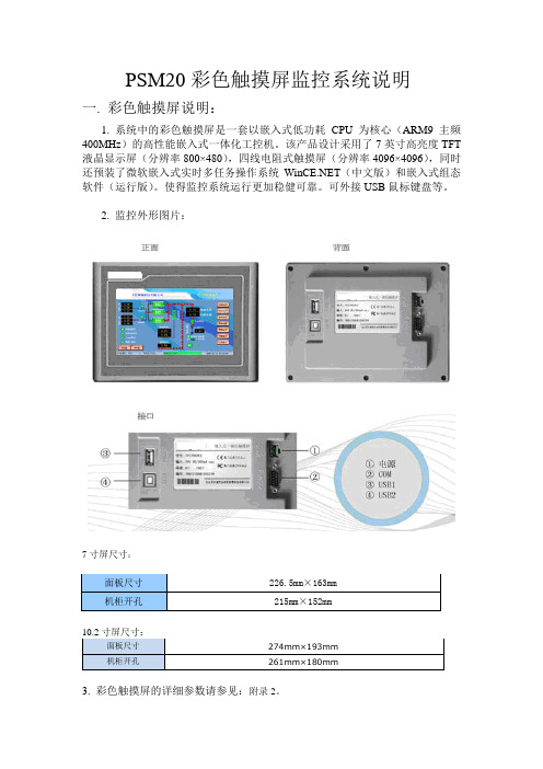
PSM20彩色触摸屏监控系统说明一. 彩色触摸屏说明:1. 系统中的彩色触摸屏是一套以嵌入式低功耗CPU为核心(ARM9主频400MHz)的高性能嵌入式一体化工控机。
该产品设计采用了7英寸高亮度TFT 液晶显示屏(分辨率800×480),四线电阻式触摸屏(分辨率4096×4096),同时还预装了微软嵌入式实时多任务操作系统(中文版)和嵌入式组态软件(运行版)。
使得监控系统运行更加稳健可靠。
可外接USB鼠标键盘等。
2. 监控外形图片:7寸屏尺寸:面板尺寸226.5mm×163mm机柜开孔215mm×152mm面板尺寸274mm×193mm机柜开孔261mm×180mm3. 彩色触摸屏的详细参数请参见:附录2。
4. 串口引脚定义:(箭头指出的是15. 监控系统连接示意:单电单充系统:可以实现1组120节电池巡检,80路开关量检测,60支路绝缘检测,16个整流模块管理。
双电双充系统:参考上面的示意图,需要注意的是彩屏的COM2 (RS485)只接综合采样(1#和2#) 的J0 (RS485)端子;电池巡检盒、开关量、支路绝缘、整流模块或CAN485协议转换器的RS485按照各自所在的组别(如:I组、II组)分别接入对应的综合采样的JP3 (RS485),请千万注意不可将2个综合采样的J4(RS485)的485网络连接起来,而应是各自独立的。
可以实现2组每组120节电池巡检,2组每组80路开关量检测,2组每组60支路绝缘检测,2组每组16个整流模块管理。
二.彩色触摸屏监控菜单操作(如有更新,恕不另行通知)请注意:说明书的图片为截图,仅供示意,请以实物显示为准;2.1主界面(常态界面):单电单充系统主界面示意:双电双充系统主界面示意:此界面显示公司标识,交直流信息,充电模式,系统通讯状态和工作状态。
通过触摸屏点击“参数设置”按钮,进入“权限管理”的界面,输入正确密码才能进入相应的界面进行参数设置修改。
直流屏监控PSM-A20直流屏监控PSM-A20是天英电力电源监控的一系列产品,直流监控PSM-A20监控专门为配置要求不高但功能又全面的的直流屏系统专门定制,具有安装方便,性价比高的优势特点,可以满足35KV以下直流屏系统的所有电力电源监控的要求。
那么,这款直流屏监控PSM-A20有哪些功能特点呢?a、安装方便,使用简单,性价比高;b、同时具备RS485\RS232接口,支持多种通信规约,全面实现“四遥”功能;c、通过液晶显示屏,实现人机界面可视化操作,全中文菜单,操作简单方便,易于上手;d、根据系统不同要求,可通过RS485总线扩展电池巡检和绝缘检测单元;e、完善的告警处理及记录功能,可通过当前故障和历史故障查询系统故障记录;f、可与艾默生等各个厂家模块配套使用;g、智能型电池充电管理功能,响应时间快,限流值稳定,延长电池使用寿命;h、可根据用户要求,开关量输入可选择辅助触点或电压信号接入;i、完善的告警处理及记录功能,当系统异常时,监控自动产生声光告警,同时屏幕上的“故障”二字闪烁,故障输出节点动作;用户可通过当前故障和历史故障查询系统故障记录;j、可现场(或远端)设定系统运行参数,上下告警限,手动均浮充转换,模块开关机控制,设置过程中系统自动提示输入范围;k、监测各直流馈电输出的电压、电流,各馈电输出开关状态、熔断器状态、绝缘状态和防雷器状态,当发生异常情况时发出声光报警;l、过压、欠压、缺相、停电告警,全自动双路交流前换功能;m、可检测13路支路馈线开关状态或跳闸告警;N、可根据用户需求通过RS485接口扩展最多24路电池巡检(配1台电池巡检单元);o、可根据用户需求通过RS485接口扩展支路绝缘监测单元,最多30路;p、可实现硅链自动调压控制功能(默认为五级硅链)直流屏监控系统在直流屏中的十大功能与作用电力电源监控技术的日益成熟,为直流屏系统的稳定运行以及监测直流屏系统中所有直流屏核心部件的故障起到十分重要的作用,那么电力电源监控直流屏监控系统在直流屏中的十大功能与作用1. 性能齐全的检测功能,系统包括主监控、交流检测单元、直流检测单元、开关量单元、电池巡检和绝缘检测单元,可以精确的监测系统各种运行参数,同时还可兼容通信模块和逆变模块;2. 严密的控制功能,包括对电池的智能化充放电管理(严格控制电池充电电压电流,延长电池使用寿命)、智能型交流双路自动切换、模块开关机和电压电流控制;3. 友好的人机界面,大屏幕液晶显示器(一个画面可显示20*15个汉字,也可显示电池组的充放电曲线),触摸屏点触式操作,全部汉字显示,操作简便,易于上手;4. 多途径告警功能,当系统出现异常时,立即产生声光告警、启动故障继电器并通过RS485和RS232传送到后台,同时主监控显示自动跳到故障信息显示画面,便于机房无人值守的科学化管理;直流屏监控系统5. 周全的设置功能,可灵活对系统进行配置(如母线分段与否、模块数量、电池组数、巡检仪和绝缘检测仪数量等)、设定各参数上下报警限、设定电流传感器变比、对故障输出节点进行配置;6. 放电计量功能,当用户要对电池组进行核定性放电时,只要在“放电计量”功能下启动放电计量,系统自动给出放电负载加载控制信号,同时调低模块输出电压(如198V),开始对电池放电,计量放电时间和放电容量,当电池电压达到用户设定的终止放电电压值时,系统又自动给出放电负载切除控制信号,恢复到正常工作状态,此时用户可根据记录下的放电容量对电池组进行评估;直流屏监控系统7. 当用户要详细的掌握电池充放电情况时,可查阅充放电曲线了解其每时每刻的电压电流值,从而进一步了解电池的使用性能;8. 采用电力部标准通信协议,同时提供RS232和RS485串行通信接口,方便与电力自动化系统对接,实现对电源系统“四遥”功能,从而达到无人值守的自动化管理的目的;9. 另外考虑到客户的具体情况,本监控系统可灵活的与任意厂家的充电模块联机(包括模拟量调节的模块和数字量调节的模块),同时软件采用开放时设计,可根据客户要求量身定做最完美的监控系统。
BEFORE USE ....Thank you for choosing M-System. Before use, please check contents of the package you received as outlined below .I f you have any problems or questions with the product, please contact M-System’s Sales Office or representatives. ■PACKAGE INCLUDES:Surge protector ....................................................................(1) ■MODEL NO.Confirm Model No. marking on the product to be exactly what you ordered.■INSTRUCTION MANUALThis manual describes necessary points of caution when you use this product, including installation, connection and basic maintenance procedures.LIMITATION APPLICABLE TO M-RESTERThe M-RESTER will protect electronics equipment from damage caused by lightning by absorbing most of the surge voltages.However, M-RESTER may not be effective against cer-tain extremely high voltages caused by a direct or almost direct hit by lightning.M-RESTER must be installed according to this installa-tion / instruction manual.GENERAL■FUNCTION & FEATURES• High discharge current capacity 20 kA (8 / 20 µs), 1 kA (10 / 350 µs)• Ultra-thin 7-mm-wide module can be mounted in high density• Excellent protection employing multi-stage SPD circuits • DIN rail mounting and grounding • Shield terminal provided■SPECIFICATIONSLINE TO LINE LINE TO EARTH SHLD TO EARTH Max. continuousoperating voltage (Uc)±32V ±160V ±160V*1Voltage protection level (Up) @4kV (1.2 / 50 µs)±60V ±800V ±800V*1Leakage current @Uc ≤ 5µA ≤ 5µA ≤ 5µA*1Response time≤ 4 nsec.≤ 20 nsec.≤ 20 nsec.*1Approx. capacitance @10 kHz1500 pF 100 pF 100 pF*1Max. discharge current (Imax)20kA (8 / 20 µs)1.0kA (10 / 350 µs)Nominal current (I N )400mA Internal series resistance 1.5Ω ±10% per line *1.V alues for the MD7PA-FF .Shortcircuited for the MD7PA-FG.POINTS OF CAUTION■ENVIRONMENT • Indoor use.• When heavy dust or metal particles are present in the air, install the unit inside proper housing with sufficient ventilation.• Do not install the unit where it is subjected to continuous vibration. Do not subject the unit to physical impact.• Environmental temperature must be within -25 to +85°C (-13 to +185°F) with relative humidity within 30 to 90%RH in order to ensure adequate life span and operation.• This unit needs a DIN rail as earth grounding bar. Ox-ide coating of an aluminium rail may lower the electric conductivity between this module and the ground. Use a steel or copper rail. ■DIELECTRIC STRENGTH TESTING• The surge protector starts discharging when 160V or greater voltage is applied between lines and earth. Re-move the grounding wire before conducting a test. Be sure to return the wire after the test. ■AND ....• We recommend that you keep spare surge protectors so that you can replace them when necessary .• Lightning surge can enter not only through signal lines but also through power supply lines. We recommend that you also use the Lightning Surge Protector for Power Lines for adequate protection.056 222 38 18SEN TRONIC AGCOMPONENT IDENTIFICATIONINSTALLATIONMount the unit on a DIN rail. Once installed, do not move it to another DIN rail.■MOUNTING THE UNIT ON A DIN RAILA) Hang the upper hook of the DIN rail mounting adaptor at the rear side of unit, on the DIN rail.B) Push in the lower in keeping pressing the unit to the DIN rail.C) DIN rails generally have slight individual variability in size. If you find it difficult to push in the lower part, go back to (A) and hang the upper part more deeply onto the rail and try (B) again.■REMOVING THE UNITA) Push down the spring loader utilizing a minus screwdriv-er.B) Confirm that it is pulled enough down and pull out the lower part of the unit.C) Detach the upper part from the DIN rail.TERMINAL CONNECTIONConnect the unit as in the diagram below .Be sure to ground the DIN rail on which the unit is mounted and cross-wire between the rail and FG terminal of the protected device as shown in Figure 1 in order to equalize the earth potential.When the unit is connected with a device which has no FG terminal, ground the surge protector only . ■EXTERNAL DIMENSIONS unit: mm (inch)8–M3 EURO■Figure 1. GROUNDINGCross-wire from the DIN rail to the metal housing of the protected device to equalize the ground potential.Ground only the surge protector when the protected device has no grounding terminal.■CAUTION WHEN WIRINGHold the module steady at the front when you tighten/loosen screw terminals.■CONNECTION DIAGRAM*1. Choose the grounding (FG) when the shield wire is to be grounded.*2. When SHLD is not isolated from PA BUS, DO NOT connect the surge protector’s terminal 7 to SHLD.*3. Oxide film on the surface of an aluminium rail may lower the electric conductivity between this module and the ground. Use a steel or copper rail.*4. Be sure to ground the DIN rail. Recommended grounding resistance max. 100 ohms.*5. Cross-wire from the DIN rail to the metal housing of the protected device to equalize the ground potential. Ground only the surge protector when the protected device has no grounding terminal.■NETWORK CONFIGURATIONDevices (Nodes)Devices (Nodes)When the distance between nodes are relatively long (e.g. grouped and separated by cabinets),install the MD7PA by each group of devices. Insert the MD7PA at the surge side of the network.For detailed information on the network, refer to that provided by PROFIBUS International.*1. Fieldbus devices complying with IEC 61158-2 operate by a supply voltage between 9V and 32V DC.Take the MD7PA’s internal series resistance into consideration when determining the cable distance if there is a large current flow on the bus line.WIRING INSTRUCTIONS■EURO TERMINALTorque: 0.3 N·mApplicable wire size: 0.2 – 2.5 mm2Stripped length: 8 mmMAINTENANCECheck surge protectors periodically. Many cases of light-ning are ignored, and even lightning at a far distance often causes inductive surges.We recommend that you check your surge protector about twice a year, before and after the rainy season. Check whenever you experience a strong lightning occurrence. Checking procedure is explained in the following:■CHECKINGWIRING1) Make sure that wiring is done as instructed in the con-nection diagram.2) Make sure that the DI N rail is connected to the metal enclosure of protected device.3) Make sure that the surge protector is securely attached to the DIN rail, and that the rail is grounded to earth.DISCHARGE ELEMENT1) Remove all wiring connected to the surge protector when you test the module.2) Check resistance across the following terminals on the high resistance range of multimeter and confirm no con-duction.Terminals (4) – (5), (4) – (DIN rail),(5) – (DIN rail), (8) – (DIN rail)The tester should show 10 MΩ or greater.For the MD7PA-FGx, (8) – (DIN rail) should show approx.0 Ω.3) Confirm conduction across the same terminals with a 500 V DC 1000 MΩ insulation tester. The tester should show 20 MΩ or less.4) I f any of the above tests shows negative, replace the surge protector.。
1. PSM-T07A 直流微机(触摸屏)监控系统
1.1 功能特点
人机界面采用7英吋800×480像素真彩TFT-LCD ,四线电阻式触摸屏,图
形化触控操作;
控制充电模块按设定的曲线对电池组充电,可以选择自动、手动、定时模式
实现均、浮充转换,电池温度系数自动补偿控制;
采集交流电压,直流电压、电流,开关量状态,电池房温度,告警干接点输
出;
监测两段直流母线,两路交流状态,支持分馈电屏管理;
通过RS485总线形式扩展开关量模块、继电器模块、绝缘监测仪、电池监测
仪,可监测支路绝缘电阻,蓄电池单体电压、单体压差;
提供一个RS232上位机通讯口,可选Modbus 、CDT91后台通讯规约; 两级密码权限管理,具有备份系统配置和参数设置的导出、导入功能; 具有系统故障保护,电流传感器异常智能保护功能。
1.2 系统配置框图
PSM-T07A监控器自动化系统
数据采集模块
开关量模块
电池仪
绝缘仪
充电模块
RS485/232
RS485
1.3 系统配置表
1.4主界面
根据系统配置会自动调用各种相对应的系统原理图作为主界面:
1.3.1 信息查询
主界面点击“信息查询”或设备图标可查询各项系统信息和运行数据:
点击“关于”查看监控系统的软件版本:
当系统出现告警时,点击主界面的“当前告警”按钮或信息查询界面,可查询当前告警记录、历史告警记录、运行数据:
1.3.2 系统配置
主界面点击“系统管理”,输入管理员密码(119119)进入系统管理界面:
系统配置界面点击“系统参数”,配置系统的接入设备和参数:
系统配置界面点击“充电模块”,设置充电参数:
系统配置界面点击“开关量”,配置ADM数据采集模块上已定义的开关量启用或禁用,常开点或常闭点接入;配置KGL开关量模块在主馈电屏或各分馈电屏上的接入个数,每个馈电屏告警量、状态量的采集路数及显示的起始标号:
系统配置界面点击“绝缘仪”,配置Ⅰ段或Ⅱ段母线上绝缘仪的接入个数,设置每个绝缘仪测量支路数、起始支路号和所安装的位置(馈电屏号):
系统配置界面点击“电池仪”,设置电池仪的测量节数:
1.3.3 参数设置
主界面点击“系统管理”,输入操作员密码(123456,出厂默认可修改)或系统配置界面点击“参数设置”进入参数设置界面:
设置监控系统对充电模块管理模式为手动或自动,当系统运行方式设置为手动模式时,充电的均浮充转换、均充时间、每个模块的开关机均为人工设置和操作;设置为自动时,充电模块按设置的曲线自动充电:
设置系统的各项告警量选择告警或不告警,指定某一或某一单元的告警通过ADM上的任意一组警继电器输出:
设置系统的告警门限:
2. 数据采集单元
2.1 ADM-T1A数据采集模块
2.1.1 功能特点
触摸屏监控器专用必选的采集模块之一,提供24V触摸屏电源;
测量1路交流电压,3路直流电压,2路直流电流,1路温度;
1路综合故障告警点,1路声光告警点;
采集9路开关量(已定义),可以选择常开/常闭点输入;
测量母线绝缘电阻;
提供1个上位机和1个下位机隔离的RS485通讯端口。
2.1.2 技术参数
交流电压测量范围:0~300VAC(相电压,真有效值);
交流电压测量精度:≤0.5%;
直流电压测量范围:0~300VDC;
直流电压测量精度:≤0.5%;
直流电流测量范围:0~800A;
直流电流测量精度:≤0.5%;
温度测量范围:0~100℃;
温度测量精度:≤±1℃;
对地电阻测量范围:2~99KΩ;
对地电阻测量精度:<±10%;
工作电源:90~300VDC。
2.1.3 端口定义
2.1.4 功能设置
1、4=ON :本机测量绝缘;
2、3:空;
4=OFF :断开绝缘仪与接地线的连接,此时绝缘测量结果应该为绝缘良好。
3. KGL-32开关量模块
3.1 功能特点
监控系统可选功能模块之一。
用于采集开关量数据;
通道采用光耦隔离,可以选择常开/常闭点输入;
通过RS485总线上传数据和扩展。
3.2 技术参数
最大采集量:32路;
通讯地址范围:0-15;
工作电源:90~300VDC。
3.3 外形尺寸及端口布置
3.4 端口定义
3.5 功能设置
通过模块正面的拨码开关设置开关量输入点的形式(常开或常闭),以及同监控器的通讯地址。
第1位:选择常开或常闭点输入
1= OFF 设置常开点输入
1= ON 设置常闭点输入
第2、3、4设置本机的通讯地址(见下表)
3.6 端口定义
3.7 功能设置
通过模块正面的拨码开关设置通讯地址。
第1位:选择常开或常闭点输入
1= OFF 设置常开点输入1= ON 设置常闭点输入。