快换接头使用说明书
- 格式:doc
- 大小:22.50 KB
- 文档页数:1
SUP自动AC摆头使用说明书宁波海天精工股份有限公司2017年6月目录一、总则 (2)二、外形尺寸 (2)三、主要性能参数 (3)四、自动AC摆头安装调试的总体步骤: (3)1. 加齿轮润滑油 (3)2. 液压管路,快插接头的检查和准备工作 (4)3. AC摆头的固定以及位置的找正 (4)4. AC摆头与机床的对接 (4)5. 对接后功能动作的测试以及电气开关位置的调整 (7)6. AC摆头精度的检查 (7)7. 主轴定向的位置调整以及试运转 (8)8. 铣头放入头库后的坐标位置 (8)五、AC摆头在使用过程中的注意事项 (9)六、AC摆头日常维护 (10)七、安装过程中的常见问题及解析................. 错误!未定义书签。
1. AC摆头连接上以后与接油盘结合面之间存在间隙 (10)2. A轴或C轴松开、夹紧以及刀具松开的动作不准确 (10)3. 附件铣头的最终精度不合格 (11)一、总则本AC双摆万能铣头(简称AC摆头)有以下特性:1. 本AC摆头可用于龙门镗铣床及五面体上,既可以实现空间曲面类零件的加工,又能满足铣、镗、钻等常规加工要求,减少了因工序转换带来的二次装夹,提高了工作效率和加工精度,2. 本AC摆头结构紧凑、布局合理,兼顾速度与刚性,尤其适合型腔类零件的加工。
3.适合槽孔内部的镗铣,端面整修,斜面倒角等加工工作。
4.主轴及齿轮采用铬锰钛合金钢并经特殊滲碳热处理可确保坚固耐用。
5.采用成对高精度角接触球轴承支撑,保证了传动的平稳性和运动的可靠性,可实现大扭矩、大切削量加工。
二、外形尺寸图一:全自动A/CAC摆头外形尺寸三、主要性能参数四、自动AC摆头安装调试的总体步骤:1.加齿轮润滑油AC摆头从包装中取出后,必须与头架一起竖直放置在工作台上,摆头对接前应从左侧注油孔加注CKC150#齿轮润滑油。
注意通过油标观察油位,加至油标1/2至2/3之间为止(约240ML)严禁超量加注,否则会对摆头造成严重损坏;并且,每工作800小时需更换一次润滑油,并清理油池铁屑。
目录图(一)高压注油泵――――――――――――――――――――――――――――――1 表(一)高压注油泵零件清单――――――――――――――――――――――――――2 图(二)高压注油泵――――――――――――――――――――――――――――――3 一.设备简介-――――――――――――――――――――――――――――――――4 二.主要技术参数―――――――――――――――――――――――――――――――4 三.设备的工作原理及结构――—————————————————————————4 (一)注油泵―――――――――――――――――――――――――――――――4 1.空气泵工作原理――――――――――――――――――――――――――4 2.柱塞油泵工作原理―――――――――――――――――――――――――5 (二)注油枪―――――――――――――――――――――――――――――――6 (三)高压软管――――――――――――――――――――――――――――-6 (四)快换接头――――――――――――――――――――――――――――――6 (五)储油筒车――――――――――――――――――――――――――――――6 四.设备的使用和保养―――――――――――――――――――――――――――――6 (一)设备使用前的准备工作――――――――――――――――――――――――6 (二)设备的保养―――――――――――――――――――――――――――――7 五.设备故障原因及排除方法―――――――――――――――――――――――――8 六.备件清单―――――――――――――――――――――――――――――――――9图(一)表(一)图(二)一、设备简介高压注油器是以压缩空气作动力的注油设备,借助泵的作用使油料产生高压,利用高压进行注油。
它是注油工艺机械化不可缺少的注油设备。
其特点是安全可靠、耗气量小,工作压力高、使用方便、生产效率高、劳动强度低,能加注各种锂基脂等粘度较大的油料。
TN-500交流凸焊机上海梅达焊接设备有限公司一、用途点、凸焊,是一种形成永久结合的金属连接方法,在焊接时焊件通过焊接电流使其局部发热,同时在焊件的接触加热处施加压力形成一个焊点。
点、凸焊目前广泛地应用于冲压结构件中以代替铆接。
本焊机为机电一体化,气压传动的点焊机,焊接过程控制精确,焊接质量稳定,主要用于焊接汽车车身部件、焊接螺钉和螺母。
二、 技术数据焊机型号单位TN-500额定容量KVA 500相数Φ 1初级电压V 380额定负载持续率% 20次级空载电压V 8.63~15.83次级电压调节级数Step 8额定级数Step 7点焊mm电极臂伸出长度凸焊mm电极臂间距离mm 200~500 可平滑调节上电极工作行程mm 25-150可平滑调节上电极辅助行程mm 0-125焊接压力KN 5-25生产率T/min气源网路中压缩空气压力Mpa 0.55压缩空气消耗率(自由状态)m3/h冷却水消耗量L/h 1080 焊机外形尺寸(长X宽X高)mm 1702X1230X2627焊机重量kg 1800三、 结构概述1.焊机组成部分:焊机组成主要有机架、焊接变压器、压力传动装置、电气系统、冷却系统和气路系统等组成。
在机身左侧面装有气路和水路控制箱,右侧面装有焊接控制器,2.焊机机架焊机机架由前面二块厚钢板和二根钢管焊接组成机身,后面由2.5mm钢板组成后箱体,机架下面底板上有4-φ20孔,作为固定焊机之用,机身上二根钢管同时作为压缩空气的储气室,以保证焊机焊接时电极压力稳定。
3.压力传动装置焊机焊接时其上电极的下降及焊件的压紧用压力传动装置来实现,压力传动装置由气缸和导轨组成。
位于气缸内的二活塞将气缸分为三室,当压缩空气进入到中气室时,下活塞便产生工作行程向下运动,而当压缩空气进入到气缸下气室时,下活塞既行上升。
气缸上气室内的压缩空气维持上活塞的位置,以保持必需的工作行程。
气缸内两个活塞全部采用Y型密封圈密封,下活塞与导轨系统相联结,导轨采用直线导轨,从而提高了导轨的随动性,保证焊接质量。
文件No.XL-OMY0002高真空L型阀XLD系列安全注意事项‐‐‐‐‐‐‐‐‐‐‐‐‐‐‐‐‐‐‐‐‐‐‐‐‐ 21.使用注意事项1 ‐‐‐‐‐‐‐‐‐‐‐‐‐‐‐‐‐‐‐‐‐‐‐‐‐ 4 (配管 , 气源)2. 使用注意事项2 ‐‐‐‐‐‐‐‐‐‐‐‐‐‐‐‐‐‐‐‐‐‐‐‐‐ 5 (设计注意事项 , 选型 , 安装 , 配管 , 维修保养)3.使用注意事项3 ‐‐‐‐‐‐‐‐‐‐‐‐‐‐‐‐‐‐‐‐‐‐‐‐‐ 7 (维修零部件)4.产品规格‐‐‐‐‐‐‐‐‐‐‐‐‐‐‐‐‐‐‐‐‐‐‐‐‐ 9 5.构造‐‐‐‐‐‐‐‐‐‐‐‐‐‐‐‐‐‐‐‐‐‐‐‐‐ 11 6.操作方法‐‐‐‐‐‐‐‐‐‐‐‐‐‐‐‐‐‐‐‐‐‐‐‐‐12 7.外形尺寸‐‐‐‐‐‐‐‐‐‐‐‐‐‐‐‐‐‐‐‐‐‐‐‐‐ 13 8.型式表示方法‐‐‐‐‐‐‐‐‐‐‐‐‐‐‐‐‐‐‐‐‐‐‐‐‐ 14 9.保证期限和保证范围‐‐‐‐‐‐‐‐‐‐‐‐‐‐‐‐‐‐‐‐‐‐‐‐‐ 15 10.零部件更换要领‐‐‐‐‐‐‐‐‐‐‐‐‐‐‐‐‐‐‐‐‐‐‐‐‐16安全注意事项此处所示的注意事项是为了确保您能安全正确地使用本产品,预先防止对您和他人造成危害和伤害而制定的。
这些注意事项,按照危害和伤害的大小及紧急程度分为“注意”“警告”“危险”三个等级。
无论哪个等级都是与安全相关的重要内容,所以除了遵守国际规格(ISO/IEC)、日本工业规格(JIS)*1)以及其他安全法规*2)外,这些内容也请务必遵守。*1) ISO 4414: Pneumatic fluid power -- General rules relating to systemsISO 4413: Hydraulic fluid power -- General rules relating to systemsIEC 60204-1: Safety of machinery -- Electrical equipment of machines (Part 1: General requirements)ISO 10218: Manipulating industrial robots-SafetyJIS B 8370: 空气压系统通则JIS B 8361: 油压系统通则JIS B 9960-1: 机械类的安全性-机械的电气装置(第1部:一般要求事項)JIS B 8433: 产业用操作机器人-安全性等*2) 劳动安全卫生法等注意误操作时,有人员受伤的风险,以及物品损坏的风险。警告误操作时,有人员受到重大伤害甚至死亡的风险。
ASK A 3M EXPERTJune, 20143M™ Dual Lock™ Reclosable Fastener SJ3871Product Description3M™ Dual Lock™ Reclosable Fasteners are positive locking, hidden fasteners designed for use in a variety ofattachment solutions. They consist of continuous strips of polyole n stems with a mushroom shaped topprotruding up from the backing. When snapped together the mushroom shaped caps interlock producing astrong reliable Fastener.The standard Dual Lock fasteners are available in three di erent stem densities (170, 250 and 400) referring tothe approximate number of stems per square inch. (26, 39, 62 stems per square centimeter) By inter-lockingdi erent stem density combinations you can create the strength that suits your application; more total stemsgive higher strength. The Dual Lock Reclosable fasteners can be mated in the following combinations ofincreasing closure strength: Type 170 to Type 250, Type 170 to Type 400, Type 250 to Type 250 and Type250 to Type 400. We do not recommend using the Type 170 to 170 because it does not have enough strengthfor a good connection. We do not recommend using the Type 400 to 400 because it is too strong and maycause stems and heads to rip out rendering the fastener no longer reclosable.The Dual Lock Low Pro le has one stem density of approximately 705 stems per square inch and theyinterlock to themselves. The low pro le products are not intended to mate to the standard size Dual Lock.There are a variety of pressure sensitive adhesives available with Dual Lock to cover most application needs.The pressure sensitive adhesive makes the Dual Lock easy to use, simply remove the liner, place the Dual Lockand apply rm consistent pressure to assure good contact with the substrate you are adhering. We also o ernon-adhesive backed Dual Lock for applications where the PSA does not meet your needs.Product Features•Easy Alignment: Dual Lock fasteners engage in any direction or position. The mushroom stems slide intoposition until they are engaged by snapping together applying rm pressure, this eliminates concerns aboutmisalignment or spontaneous engagement.•Positive Locking: Dual Lock fasteners engage/fasten with an audible snap and detectable movement assuringcomplete and secure closure.•Reclosability: Dual Lock fasteners can be opened and closed for multiple closure applications (high cyclelife).•Blind Attachment: Dual Lock fasteners can be attached on the backside of substrate (i.e. trim piece) where itwill not interrupt the show surface.•Rattle-Free: Dual Lock fasteners will not rattle loose.•Ease of Assembly: Dual Lock fasteners can be used to attach components before they enter the nalassembly plant, reducing the number of parts and the assembly time. No tools are required.•Adjustable Strength: By selecting di erent combinations of the various stem densities of the Dual Lock thefastener can be designed to meet the strength needs of the designer.•Product Forms: Dual Lock fasteners come in a variety of forms: Backed with Pressure Sensitive adhesive,Non-woven, Rigid backed, Die Cut Shapes, and low pro le.•Attachment Methods: The wide varieties of Dual Lock fasteners allow a design engineer exibility to be ableuse and attach Dual Lock to just about any substrate or application. Peel and stick pressure sensitive adhesivebacked is quick and easy yet strong and secure. Non-woven backed can be used with a variety of adhesivechoices such as hot melt, liquid, epoxies, sealants, etc. We have parts that can be attached with a screw orrivet; rigid and plain backed for developing your own special device.General InformationPressure Senstive Adhesive backed productProduct Family: Modi ed Acrylic PSA very conformable for low surface energy attachmentTechnical Information NoteThe following technical information and data should be considered representative or typical only and should not be used for speci cation purposes. Typical Physical PropertiesProperty ValuesDual Lock Color BlackAdhesive Color Dark GreyThickness 3.71 mm146 milEngaged to itself or to one of the same family 6.15 mm242 milStems62 Stems/cm²400 Stems/in²Liner Material Silicone treated Polyole nLiner Thickness0.13 mm 5 milLiner Color RedTypical Performance CharacteristicsProperty ValuesTemperature Resistance60 °C140 °FDynamic Tensile (Engage)Substrate9 N/cm²13 lb/in²Type 170 to 25014.5 N/cm²21 lb/in²Type 170 to 40015.2 N/cm²22 lb/in²Type 250 to 25021.4 N/cm²31 lb/in²Type 250 to 40018.5 N/cm²27 lb/in²Low Pro le to Low Pro le Property: Dynamic Tensile (Engage)Dynamic Tensile (Disengage)Substrate18.5 N/cm²27 lb/in²Type 170 to 25029.6 N/cm²43 lb/in²Type 170 to 40029.6 N/cm²43 lb/in²Type 250 to 25041.4 N/cm²60 lb/in²Type 250 to 400Property: Dynamic Tensile (Disengage)Dynamic Shear Substrate9.8 N/cm²14 lb/in²Type 170 to 25014.5 N/cm²21 lb/in²Type 170 to 40015 N/cm²22 lb/in²Type 250 to 250 41.3 N/cm²59 lb/in²Type 250 to 400 Property: Dynamic ShearCleavage Strength Substrate21 N/cm width12 lb/in width Type 170 to 250 35 N/cm width20 lb/in width Type 170 to 400 42 N/cm width24 lb/in width Type 250 to 250 56 N/cm width32 lb/in width Type 250 to 400 Property: Cleavage Strengthnotes: Rigid backed from Rigid backedT-Peel Adhesion Substrate1.2 N/cm width0.7 lb/in width Type 170 to 2502.5 N/cm width 1.4 lb/in width Type 170 to 4003.3 N/cm width 1.9 lb/in width Type 250 to 250 2.6 N/cm width 1.5 lb/in width Type 250 to 400Property: T-Peel Adhesionnotes: Flexible from Flexible90° Peel Adhesion Substrate3.2 N/cm width 1.8 lb/in width Type 170 to 250 5.4 N/cm width 3.1 lb/in width Type 170 to 400 8.1 N/cm width4.1 lb/in width Type 250 to 250 8.1 N/cm width 4.6 lb/in width Type 250 to 400Property: 90° Peel Adhesionnotes: Flexible from RigidCycle Life Substrate1000Type 170 to 2501000Type 170 to 4001000Type 250 to 2501000Type 250 to 400Property: Cycle Lifenotes: Number of closures before losing 50% of original strengthNoteThe following technical information and data is intended as a guideline to assist customers in selecting 3M™ Reclosable Fasteners for further evaluation. This technical information is not product release speci cations or standards. Unless stated di erently, the typical system performance and product properties were obtained using speci c test methods under controlled laboratory conditions of 72°F± 5°F and 50% ± 10% relative humidity. The user is responsible for evaluating 3M reclosable fasteners under expected use conditions to ensure suitable performance for the intended application.These are typical values which were gathered from testing the PSA backed materials. Similar values can be expected when the Dual Lock is held securely in a rigid fashion.Tests were run at 12 inches per minuteProduct Performance:Additional Informationnotes: This guide should assist you in determining which product will adhere best to your substrate for.Family GroupReferencesISO StatementTechnical InformationDesign Considerations• As a general rule, four square inches of fastener area per pound of static tensile or shear load to be supported is suggested as a starting point for evaluation. More or less area may be needed depending on speci c conditions or end use applications. Type 250 Dual Lock Reclosable fasteners less than 0.75" (19 mm) width should not be engaged to other type 250 Dual Lock Reclosable fastener as low disengagement values may occur.• Whenever possible design one side of the Dual Lock reclosable fasteners to be larger than the mating side. This will allow for variability or mismatch in Dual lock alignment positions, and ensure 100% fastening area contact. Another approach would be to design two rectangular shaped fastener pieces so that they can be engaged in a cross web/perpendicular pattern (crossed).• Dual Lock strength is proportional to the fastening contact area, and the number of stems in combination used. More stems and more Dual Lock used gives you more strength, less stems combined and using less Dual Lock will give you less strength.• Dual Lock disengagement strength/performance is strongest in direct tensile. Peel/cleavage mode is where it is most easily removed.• Final product performance depends upon a combination of factors: the substrate and its surface characteristics, the fastener selected, the application method and conditions, the time and environmental conditions required for the application. Because these factors are unique to each application, the user must evaluate Dual Lock and do any testing required to determine Dual Lock’s suitability for the user’s desired end use.Storage and Shelf LifeTo obtain best performance, use this product within 24 months from date of manufacture.SJ3870SJ3871SJ3872Thickness (mm) 3.713.713.71Liner Material Silicone treated Polyole n Silicone treated Polyole n Silicone treated Polyole n Liner Thickness (mm)0.130.130.13Liner ColorRedRedRed1. Product PageUrl: https:///3M/en_US/company-us/all-3m-products/~/3M-Dual-Lock-Reclosable-Fastener-SJ3871?N=5002385+3293242272&rt=rud 2. Safety Data SheetUrl: https:///3M/en_US/company-us/SDS-search/results/?gsaAction=msdsSRA&msdsLocale=en_US&co=ptn&q=SJ3871This Industrial Adhesives and Tapes Division product was manufactured under a 3M quality system registered to ISO 9001 standards.The technical information, recommendations and other statements contained in this document are based upon tests or experience that 3M believes are reliable, but the accuracy or completeness of such information is not guaranteed.Product UseWarranty, Limited Remedy, and Disclaimer Limitation of LiabilityIndustrial Adhesives and Tapes Division 3M CenterSt. Paul, MN 55144-1000800-362-3550 Please recycle.© 3M 2018. All Rights Reserved.The brands listed above are trademarks of 3M.Many factors beyond 3M’s control and uniquely within user’s knowledge and control can a ect the use and performance of a 3M product in a particular application. Given the variety of factors that can a ect the use and performance of a 3M product, user is solely responsible for evaluating the 3M product and determining whether it is t for a particular purpose and suitable for user’s method of application.Unless an additional warranty is speci cally stated on the applicable 3M product packaging or product literature, 3M warrants that each 3M product meets the applicable 3M product speci cation at the time 3M ships the product. 3M MAKES NO OTHER WARRANTIES OR CONDITIONS, EXPRESS OR IMPLIED, INCLUDING, BUT NOT LIMITED TO, ANY IMPLIED WARRANTY OR CONDITION OF MERCHANTABILITY OR FITNESS FOR A PARTICULAR PURPOSE OR ANY IMPLIED WARRANTY OR CONDITION ARISING OUT OF A COURSE OF DEALING, CUSTOM OR USAGE OF TRADE. If the 3M product does not conform to this warranty, then the sole and exclusive remedy is, at 3M’s option, replacement of the 3M product or refund of the purchase price.Except where prohibited by law, 3M will not be liable for any loss or damage arising from the 3M product, whether direct, indirect, special, incidental or consequential, regardless of the legal theory asserted, including warranty, contract, negligence or strict liability.。

半挂车系列使用说明书辽宁融富通铝业股份有限公司前言我公司新开发研制的系列半挂车采用优质铝合金材料,结构先进、性能优良、使用可靠、维修方便。
使用本半挂车可有效地提高运输效率、降低运输成本、增加经济效益,是理想的公路运输用车。
为使您了解本半挂车的结构、性能、使用、维修及维护保养,充分发挥半挂车的使用效能、有效地提高使用寿命,特编制本说明书,请您按照本说明书的要求,正确操作、合理使用、及时保养和维修。
本说明书仅对半挂车的结构、性能、使用及维护保养方法做重点说明。
牵引车部分按《牵引车使用说明书》进行使用和保养。
您在使用过程中如果发现该半挂车有什么问题,或者还有什么要求,请及时反馈给本公司,本公司竭诚为用户服务,尽力满足用户的需求。
目录一、外形简图二、主要技术参数三、使用范围四、使用保养及注意事项五、各主要总成的结构特点及使用与保养六、产品的运输与贮存七、质量保证八、随车工具、备件及技术资料一、半挂车外形简图二、主要技术参数1、__________型厢式半挂车型号:外形尺寸(mm):长宽高车厢栏板内尺寸(mm):长宽高最大总质量(kg):轴荷(kg):牵引销处半挂车三轴整车整备质量(kg):额定载质量(kg):半挂车轮距(mm):半挂车轴距(mm):后悬:车轮:轮胎规格:车轮数量(个):轮胎气压(KPa):轮辋形式:轴数:离去角三、列车的使用范围:本半挂是公路用车,即在道路条件较好的情况下,能充分发挥其效能。
如在道路条件较差的情况下,要限制使用,即采取减载缓行等措施。
四、列车的使用保养及注意事项:1、牵引车与半挂车的脱开:(1)将列车停在平坦的场地或路面上,摇下支撑装置,使其在接触地面后充分受力,关闭气分离开关,拔下电源插销以及ABS插销、取下气路联接器(即气接手),脱开牵引座板锁勾。
(2)关闭牵引车手制动阀,将牵引车缓缓开出,牵引车与半挂车即可脱开。
2、牵引车与半挂车的结合:(1)向后缓缓倒牵引车,接通七孔电源插座、ABS插座及气路联接器,打开分离开关,接合半挂车牵引座板撞车,锁勾即可锁住牵引销。
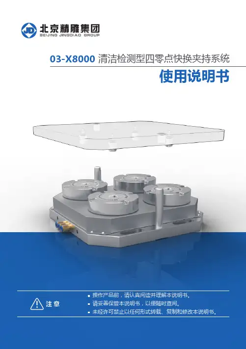
使用说明书注 意操作产品前,请认真阅读并理解本说明书。
请妥善保管本说明书,以便随时查阅。
未经许可禁止以任何形式转载、复制和修改本说明书。
清洁检测型四零点快换夹持系统03-X8000产品介绍2产品装配示意图及配件尺寸明细3产品概述2零点快换技术优势2清洁检测型四零点快换夹持系统(03-X8000)产品特性2产品工作要求2零点快换 JD-ZCS-115A:03-30024底板 D4-150A:03-80014拉钉 A型:03-10035拉钉 B型:03-200355拉钉 C型:03-60036禁止事项6使用方法7气压检测功能使用说明8校正方法9零点快换使用标准10零点快换使用注意事项10保养与维护11常见故障分析与排除11安全及保护措施双零点快换夹持系统及明细表3产品概述精雕零点快换夹持系统主要由快换底板、快换本体、拉钉、角度定位器、转接板等组件构成,采用模块化结构设计,应用灵活,根据工件大小等因素,可单独使用,也可多个组合使用。
本夹持系统采用加压释放、泄压锁紧的气动工作模式,锁紧状态下,具有一定的自锁能力,能够适用于钻、铣、铰、镗、磨等各种加工工艺。
本夹持系统定位准确,运行稳定,操作便捷,可广泛用于三轴、四轴、五轴机床,适用于各种半自动和自动化加工,能够大大提高生产节奏、提升工作效率、提升机床利用率。
使用零点快换可以实现以下几点:机内上下料工作转移到机外,大大缩短停机时间,同时提高了人员作业的安全性;标准化的接口,使得夹具结构及设计可以模块化、标准化,使生产管理简化;通过托盘,实现工装的快速转换,实现共线生产,柔性高,降低夹具制造周期和成本;解决了多工序加工或检测的重复定位和装夹问题。
零点快换技术优势结构简单,具备足够的自锁能力;运行稳定性好;定位精度高:a、中心定位采用锥面配合,定位精度高、稳定;b、旋转方向采用角度定位器进行定位,其定位精度更高;可根据工件大小,自由组合使用;预留直接检测运动部件的位置,便于增加运行状态检测信号,增加自动化加工可靠性。
ZDY-750型煤矿用液压坑道钻机使用维护说明书重庆淑维机电设备制造厂感谢您选购本产品!为了保证安全并获得最佳效能,安装、使用产品前,请详细阅读本使用说明书并妥善保管,以备今后参考。
随着技术的进步和产品的不断更新,如果本《使用说明书》中未涵盖的内容,请与我厂联系。
执行标准: MT/T790-2006Q/SZC009-2007版本号:出版日期:安全警示:1)所有操作人员必须经培训合格,并持有上岗证,方可可进行操作;2)严禁带电拆卸任何隔爆型零部件和带电移动钻机;3)钻机安装时,钻场周围的岩层应安全可靠,且有足够空间,通风良好,泵站电机一侧应置于进风侧;4)钻机必须安装锚固,不得有松动现象;5)钻机在试车时,在场人员应站在钻机侧面,并保持一定距离;6)严禁在运行中拆卸液压元件;7)液压系统不得在泄漏状态下运转,当液压油有泄漏时,应及时清理、掩埋;8)电动机应使用YBK型防爆电动机;9)严格按照说明书要求调节压力;10)非专业人员不得随意拆装和维修钻机。
液压件损坏或需更换时,须向原厂家购买更换,严禁用户随意配制更换。
11)选用防爆电动机及液压胶管应具有有效期内安标证。
1、概述 (1)2、主要结构和工作原理 (1)3、主要技术参数 (2)4、地面试车 (2)5、下井运输 (3)6、井下安装试车 (3)7、钻孔操作 (4)8、保养、维修 (4)9、常见故障分析与处理方法 (4)10、贮存保管及运输 (5)11、生产厂保证、售后服务事项 (5)12、安标控制件明细表 (5)13、装箱单 (6)1 概述本使用说明书按工业产品使用说明书总则的规定编写。
产品特点ZDY-750型煤矿用液压坑道钻机(以下简称钻机)是重庆淑维机电设备制造厂新研制的ZDY系列钻机之一。
该钻机是结合煤矿现场使用的最新需求和改进意见而设计制造的。
该钻机采用液压传动机构,具有钻进能力大、速度快、操作简单、工作稳定可靠、移动安装方便等特点。
适用范围该钻机主要用于煤矿井下钻进瓦斯抽(排)放孔、注浆灭火孔、煤层注水孔、防突卸压孔、地质勘探孔及其它工程孔。
气动工具一般安全要求(GB17957-2000)前言本标准主要参考美国标准ANSIB186.1-1984《轻便式气动工具安全规程》起草,同时参考了其他国外类似标准。
本标准从2000年6月1日起实施。
本标准由中华人民共和国国家经贸委安全生产局提出并归口标准负责起草单位:吉林省劳动保护科学研究所。
本标准主要起草人:郑凡颖、肖建民、茹海亭。
1. 范围本标准规定了气动工具(以下简称工具)的设计、制造、管理、使用、检查与维修的一般安全要求。
本标准适用于生产和施工过程中使用的以压缩空气为动力的轻便式工具。
本标准不适用于气动机械设备。
2. 引用标准下列标准所包含的条文,通过在本标准中引用而构成为本标准的条文。
本标准出版时,所示版本均为有效。
所有标准都会被修订,使用本标准的各方应探讨使用下列标准最新版本的可能性。
GB 2494-1995 磨具安全规程GB4674-1984 磨削机械安全规程GB/T4974-1989 压缩机、凿岩机械与气动工具优先压力GB/T5898-1986 凿岩机械与气动工具噪声测量方法工程法GB 8916-1987 机械设备防护罩安全要求GB/T8910.1-1988 凿岩机与气动工具振动测量方法总则GB/T8910.2-1988 凿岩机与气动工具振动测量方法冲击式机器的测量GB/T8910.3-1988 凿岩机与气动工具振动测量方法回转式机器的测量GB10434-1989 作业场所局部振动卫生标准GB/T15706.1-1995 机械安全基本概念与设计通则第1部分:基本术语、方法学GB/T15706.2-1995 机械安全基本概念与设计通则第2部分:技术原则与规范3 定义本标准除了采用GB/T15706.1中的定义外,还采用下列定义:3.1 手动开关阀 positive on-off throttle靠手动改变其开关位置并可保持在所设定状态的阀门。
3.2 手动压阀 constant pressure throttle一种常闭式阀门,由手(或手指)在阀门操纵部位施加一定压力时开启,压力取消时自动关闭。
Z D Y系列煤矿用全液压坑道钻机说明书LEKIBM standardization office【IBM5AB- LEKIBMK08- LEKIBM2C】ZDY系列煤矿用全液压拖车式坑道钻机产品使用说明书尊敬的用户:感谢你选购本产品!为了保证安全并获得最佳效能,安装、使用产品前请详细阅读本使用说明书并妥善保管,以备今后参考。
本公司服务热线:电话:9传真:8邮编:317000网址:地址:浙江省临海市塘渡工业区浙江锦德矿山机械设备有限公司执行标准:MT/T790Q/JD02-2013版次号: BC01出版日期: 2013年01月警告禁止在井下和有爆炸性气体的环境中拆卸和维修电动机!电动机必须配用YBK系列煤矿井下用隔爆型三相异步电动机。
液压胶管应符合MT98的规定,并在检验合格证有效期内。
禁止液压系统在泄漏状态下工作!发现泄漏立即关机处理。
禁止液压泄漏渗油滞留工作现场!及时清理干净。
禁止随意更换零部件!目录1.用途及使用范围 (4)2.主要结构和工作原理 (4)3.主要技术参数 (18)4.地面试车 (20)5.下井运输 (21)6.井下安装试车 (21)7.钻孔操作 (22)8.保养、维修 (23)9.常见故障分析与处理方法 (23)10.贮存、保管 (24)11.开箱检查 (25)12.其他 (25)13.产品资质编号 (25)1、用途及使用范围主要用于煤矿井下钻探各种角度的瓦斯抽(排)放孔、煤层放水孔、注浆灭火孔、地质孔、及其它用途的各种工程孔,也可用于地面,钻探地质勘探孔及其他用途的各种孔。
适用于岩石坚固系数F≤8的各种煤层、岩层。
要求巷道或钻场断面大于平米,高度大于米,宽度大于米2、主要结构和工作原理钻机的整体结构:主要由泵站、动力头、机架、机座、操纵台和钻具6部分组成。
(图)液压系统:(图)液压系统主要零件目录序号名称图号数量/件备注1油箱ZDY750-01011容量125L2网式过滤器MF-1013防爆电机YBK2-****-41(安标受控)4进油管33X18015双联齿轮泵2CB-FE50/10F1额定压力20MPa 6主溢流阀YF-20H2-S1额定压力20MPa 7压力表62/25MPa2额定压力25MPa 8多路阀JCF-L15E-5-4471169快换接头B15/M27X2、B20/M33X210液压马达BM5-****111节流阀L-10H112推进油缸63TJYG860-00113夹持器JCQ1114液压卡盘15卡盘连接油管8/1(安标受控)16夹持器连接油管8/2(安标受控)17推进油缸连接油管8/2(安标受控)18节流阀连接管8/2(安标受控)19马达连接管16/2(安标受控)20压力表连接管6/2(安标受控)21回油管25/8001(安标受控)22冷却器1额定压力23精密过滤器2U-A100/21额定流量100L 24副溢流阀YF-L10H1额定压力20MPa 25副泵出油管10/6001(安标受控)26主泵出油管16/6001(安标受控)泵站泵站主要由电动机、油泵、油箱、溢流阀、精粗滤油器、冷却器、及底座等部件组成。
快速接头使用说明及注意事项
请操作者理解并遵循所有的说明,警告和预防,如未遵循所有的说明,警告和预防可能导致肉体的伤害和财产的损失。
使用说明:
1.用干净不脱毛抹布擦拭干净快换接头阴阳两极。
2.在电动机未启动的情况下,向下推动内抓迅速将阳接头插入阴接头,检查是否到位。
3.启动电动机。
4.调试完成后先关闭电动机,后向下推动内抓快速将阳接头拔出阴接头。
警告和预防:
1.不要过度的在接头上旋转、扭曲、弯曲、震动、而施加压力,这有可能损坏接头并导致产品故障、漏油和失灵。
2.当周围温度或液压油温度大于80°,作为工作温度的环境,这有可能导致产品故障、漏油或失灵
3.不要使用管子胶水或其他的螺纹密封液体,只可用特氟伦带用于螺纹密封。
4.除非是要把管子从接头里分离出来,否则不要把内抓推向主体,快换接头的锁卡的作用是避免连接的不经意的脱离。
安装特殊说明:
1.当快换接头连接时,偶尔会发现阳接头被夹紧,但是还尚未完全密封,像这样的情况,需再次深深地推入阴接头至完全连接,如不完全推到位的话会引起漏油。
2.当拧螺纹接头时不可过度使接头转矩过大,这有可能会损坏接头并引起漏油或其他不良现象。
3.不要过分振动、旋转、牵拉、扭曲、弯曲和超负荷敲打快换接头,这样可能造成快换接头损坏。