中英文安装说明书
- 格式:pdf
- 大小:671.92 KB
- 文档页数:13
DXN7 系列户内高压带电显示装置安装使用说明书Installation and Operation Instructions forDXN7 Serial Indoor High-voltage Live Display Device1.适用范围1. Applicable Range1.1DXN7 系列户内高压带电显示装置(以下简称显示装置),适用于户内额定电压为3, 6, 10,27. 5, 35KV; 频率为50H Z D的开关设备上,用以反映显示装置处高压回路带电状况。
1.1 DXN7serial indoor high-voltage live display device (referring to as the display devicethereinafter) is suitable for the indoor switchgear with rated voltages of 3, 6, 10, 27.5, 35KV and frequency of 50Hz to reflect charged state of high voltage circuit at the display device.1.2显示装置中支柱绝缘子式传感器,可以与各类型高压开关柜、隔离开关、接地开关等配套。
1.2 The post insulator style sensor in the display device can be matched with all kinds of highvoltage switch cabinet, isolation switch and grounding switch etc.1.3显示装置不但可以提示回路带电状况,而且还可以与电磁锁配合,实现强制闭锁开关柜操作手柄及网门。
达到防止带电关、合接地开关、防止误入带电间隔的目的。
提高开关设备防误性能。
1.3 The display device can not only prompt charged state of the circuit but also be cooperatedwith the electric magnet lock to compulsory lock the operation handle of the switch cabinet and the gate of the grid thus to prevent live switching on/off of grounding switch, prevent access into live isolation and rise up error action of the switchgear.1.4正常使用环境条件1.4 Environmental condition for normal operation1.4.1 普通型1.4.1 Normal Typea. 安装地点不超过海拔高度1000ma. The installation site should be no higher than 1000m above sea level.b. 周围环境温度上限值为40°C,下限值为:-25°Cb. The upper limit of ambient temperature is 40°C while the lower limit is -25°C.c. 相对湿度在环境温度为20C时,日平均不大于95 %c. The daily relative humidity in average under ambient temperature of 20°C is no higherthan 95%.d. 周围空气无明显地受尘埃、腐蚀性易燃性气体、水蒸气或盐雾等污染的场所。

SZ HUANAN SANXIAN TECHNOLOGY CO.,L目录安全信息包装说明简介主板图解安装与设置驱动程序的安装BIOS设置安全信息此包装中包含的组件有可能静电放电(ESD)损坏。
请遵守以下注意事项,以确保成功组装计算机确保所有组件连接牢固。
若连接不紧可能会导致计算机无法识别组件或无法开启拿取主板时为防止静电损坏其配置,请在拿取主板前通过接触其它金属物体释放自身的静电拿起主板时请手持主板边缘,避免触及主板的敏感组件在不安装主板时,请将主板放在静电屏蔽容器或防静电垫上在打开计算机前,确保计算机机箱内的主板或任何位置上没有松动的螺丝或金属组件在安装完成之前不要启动计算机。
否则可能会导致组件永久性损坏以及伤害使用者在任何安装步骤中,如果您需要帮助,请咨询专业的售后客服人员安装或拆卸计算机任何组件之前,请先关闭电源,并将电源线由插座上拔除本主板须远离湿气保留本用户指南以供将来参考后置I/O面板.........................................................................................................................................................................................................................................................................................................................................................................................................................................................................................................����������在电源供应器连接到电源插座之前,请确保您的插座提供了电源供应器上额定相同的指示电压有液体渗透至计算机内主板暴露于水气当中主板不工作,或您依照使用指南后仍无法让本主板工作主板曾掉落且损坏主板有明显的破损痕迹包装说明请确认您所购买的主板包装是否完整,如果有包装损坏或是任何配件损坏、短缺的情况,请尽快联系我们�.SATA数据线 �根简介特点介绍发生下列任一状况时,请将本主板交由维修人员检查:将电源线摆放在不会被人踩到的地方,不要在电源线上放置任何物品�.华南金牌X��-F�D 主板一片�.I/O后挡板一块�.保修卡一张�.用户手册一本CPU: 英特尔® LGA����-�处理器 英特尔® 志强™ 英特尔® LGA����-� �/�代 英特尔® 酷睿™RAM: �*DIMM 最大支持���GB DDR�����/����/����MHZ 非ECC.ECC内存 四通道存储器体系结构实际内存数据速率取决于CPU类型和DRAM模块I/O特效: � x SATA�.�(最大传输速度高达�GB/s) � x SSATA�.� � x USB�.�接口 � x USB�.�接口 � x RJ�� 网卡接口: Realtek 音讯转码器Realtek �.�环绕声高清晰度音频编解码器音频 音源输出: 前置输出/前置喇叭输出,后置喇叭输出, 中置/重低音喇叭输出,光纤音频输出音源输入: 麦克风输入,音频输入: � x Realtek ����MB/S 以太网以太网扩展插槽: � x PCIe �.� x��� x M.� NVME PCIe �.�X� (key M)����/����/���� � x M.� NVME PCIe �.� X�(key M)/M.� NGFF(SATA �.�) ����/����/����状态描述关网络未连接黄色网络已连接闪烁网络数据在使用中速度灯号状态描述关传输速率 �� Mbps绿色传输速率 ��� Mbps橙色传输速率 � Gbps连线/工作灯号图�-� X��-F�D主板图解图�-� 整体后置I/O面板展示图�-� LAN端口状态表图�-� 音频端口配置音频端口音频输入音频输出/前置喇叭输出后置喇叭输出中置/重低音输出侧置喇叭输出麦克风输入通道����后置I/O面板音频接口网络接口USB�.�接口USB�.�接口网络接口USB�.�接口主板图解�*SATA�.�M.� NGFF接口�*SSATA�.�开机按钮重启按钮前置USB�.�前置USB�.�DDR�*�插槽USB�.�接口USB�.�接口(下)千兆网卡(上)音频接口四针风扇接口四针风扇接口三针风扇接口三针风扇接口三针风扇接口三针风扇接口PCIEX��接口M.� NVME接口AUDIO前置音频��P主板供电接口�P CPU供电接口�P CPU供电接口�V 两针MOS风扇接口PCIEX��接口PCIEX��接口CPU�CPU��V 两针MOS风扇接口�V 两针MOS风扇接口�V 两针MOS风扇接口安装与设置请仔细查看主板,凡有表明“�”或是白色粗线标记的接脚均为�脚位置。
BCQ系列起重限制器安装说明书BCQ series overload limiter installation instructions安装前注意事项(Notice before installation):●安装前请核对本产品型号是否符合您的起重设备。
Please check whether this model can meet your lifting equipment before installation.●开机后检查本机是否能正常工作。
Check whether the equipment can work normally after switch on.●本产品的供电应不受任何控制电器的控制(电源总开关除外)。
Power supply of the products shall be free from any electrical control (except thepower master switch)●本产品禁止在雨淋和强腐蚀环境下工作,如在户外应加装有防雨措施。
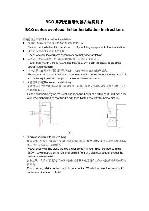
This product is banned to be used in the rain and the strong corrosive environment, it should be equipped with rainproof measures if used in outdoor.1. 传感器的安装(The sensor installation)传感器必须安装在电动葫芦钢丝绳固定端,将钢丝绳嵌入传感器固定块内(如图一示),拧紧螺栓即可。
Fix the sensor directly on the steel wire rope(fixed end) of electric hoist, and make the wire rope embedded sensor fixed block, then tighten screw.(refer below picture)图一2. 接线(connection with electric box)电源接线:将带有“380V”标示的两根电源线接入380V电源,电源应不受其他电器设备的控制(电源总开关除外)。

Instruction Manual of Installation and Operationfor220kV Power Transformer目录Content1.适用范围 (3)Applicable Scope (3)2.运输及起吊 (3)Lifting and transportation of transformer main body (3)2.1运输要求 (3)Transportation Requirements (3)2.2主体运输 (4)Transportation of Transformer Main Body (4)2.3主体起吊 (4)Lifting of Main Body (4)2.4主体牵引 (5)Traction of Main Body (5)3.验收和保管贮存 (5)Acceptance and Storage (5)3.1到货验收 (5)Acceptance after Transformer Arrival (5)3.2附件开箱检查验收 (6)Inspection and Check of Accessories’ Boxes (6)3.3保管及贮存 (6)Storage (6)3.4 绝缘油的管理 (7)Insulation Oil (7)4.整体复装 (8)Re-assembly (10)4.1整体复装的注意事项 (10)Notes for Re-assembly (10)4.2组装前的准备工作 (11)Preparations before re-assembly (11)4.3整体复装 (11)Transformer re-assembly (11)5.真空注油 (13)Vacuum oil-filling (13)5.1真空注油 (13)Vacuum oil-filling (13)5.2补充注油及静放 (15)Supplementary oil-filling and placing still (15)6.交接试验和试运行 (16)Site Acceptance test and Commission (16)6.1试验前的检查 (16)Check before Site Acceptance Test (16)6.2交接试验 (17)Site Acceptance Test (17)6.3 试运行前的检查 (17)Inspection before Trial Operation (17)6.4投入试运行 (18)Put into trial operation (18)7.运行维护 (19)Maintenance in (service) operation (19)7.1正常运行 (19)Normal operation (19)7.2维护 (20)Maintenance (20)7.3变压器故障分析和排除 (21)Analysis and elimination of transformer faults (21)7.4螺栓紧固外加(最大)力矩 (23)1. 适用范围Applicable Scope本说明书适用于220kV油浸式电力变压器。
上海通用风机股份有限公司通用风机安装维护使用说明书目录Content页次page 一、安装概述Summarize of installation (2)⒈风机安装场所P o s i t i o n (2)⒉风机安装空间要求D e m a n d s o f space (2)⒊各种安装方法及要求Methods and demands of installation (3)⒋吊装于天棚的场合Situation of loaded on the ceiling (5)二、基础B a s i c (5)⒈混凝土基础C o n c r e t e b e d r o c k (5)⒉减振元件S h a k e p r o o f e l e m e n t (6)⒊减振元件的使用Using of the shakeproof element (7)三、搬运T r a n s i t (7)⒈部件检查C h e c k t h e p a r t s (8)⒉吊装及搬运Hoi st and t ransi t (8)⒊保管S a f e k e e p i n g (8)四、安装方法M e t h o d s o f i n s t a l l a t i o n (9)⒈水平校正P l a n e e m e n d a t i o n (9)⒉轴承座的安装Installation of bearing house (10)⒊确认电机转向Notarized the motor direction (13)⒋带轮及胶带P u l l ey and V-bel t (13)⒌联轴器校正S haft joint emendation (13)⒍管道连接J o i n o f p i p e (14)⒎热风机的安装Installation of hot-air blower (14)五、试车C o m m i s s i o n i n g (15)⒈检查C h e c k i n g (15)⒉加油P u t o n s t e a m (15)⒊盘车J i g g e r (15)⒋送风系统A i r-f e e d i n g s ys t e m (16)⒌电气配件E l ect ri c fi t t i ngs (16)⒍启动S t a r t u p (16)⒎运行确认N o t a r i z e t h e r u n n i n g (17)六、保养与管理M a i n t e n a n c ea n d m a n a g e m e n t (18)⒈定期检查P e r i o d i c c h e c k (18)⒉日常检查D a i l y c h e c k (22)⒊轴承的保养和检查Maintenance and checking of bearing (23)⒋联轴器的保养和检查Maintenance and checking of shaft joint (26)⒌胶带及带轮的保养和检查Maintenance and checking of pulley and V-belt (26)七、安全须知S afet y caut i on (29)非常感谢您选用创新精良的“上树”牌风机!First, thanks for selecting our innovative and excellent fans with “上树” brand!正确的安装和维护关系到风机性能及使用寿命。
箱式变电站产品Series Compacted Package Sub-station安装使用说明书O peration Manual1.概述GeneralXBJ1系列紧凑型箱式变电站是由天津电气传动设计研究所组织全国百余家企业联合开发的新产品,它吸收了美式箱变、欧式箱变和国产箱变三大派别的优点,采用了新材料新工艺及先进的元器件和高低压自动化技术;其中高压侧能满足电力部门对于配电网自动化的要求,低压侧能满足小区物业管理智能化的要求。
该系列箱式变电站是由高压单元、电力变压器、低压单元、计量单元及智能系统等,优化组合成的完整的智能化供配电成套装置,它功能多,用途广,运行安全可靠,外型美观,并具有安装方便,少占地,少维护,少投资,见效快,寿命长等特点。
可作为城市建筑、居民小区、市政设施、工厂、矿山、公路、码头、油田及施工临时用电等部门、场所的变配电设备。
XBJ1 series intelligent package sub-station is new products developed by Tianjin Electric Transmission Project Institution and other hundreds of companies. The new products combine the advantages of package sub-station from US, European, and China to fit in the situation in our country. New materials, new process and advanced components and automatic technology for high and low voltage are used in the products; the high voltage siding satisfies the requirement of the automation of power supply network from power supply departments and the low voltage siding satisfies the requirement of community intellectualization. XBJ1 series intelligent cabinet transformer station is composed of optimizing the configuration of high voltage components, power transformer, low voltage components, measurement components and intelligent system. It is multifunction and has wide applications. It is able to run reliable and environment friendly. It has beautiful outlooks and id easy to be installed. It has the advantage of taking up less land, les maintenance, less investment, long lifetime. It can be used as power transform and distribution equipment in city construction, communities, city facilities, factories, mines, road construction, harbor, oilfields and can be also used as temporary construction power supply equipment.2.型号说明Symbol ExplanationX B J 1 —37 /0.315M J 1000变压器容量Rated power 1000kVA外壳材料Enclosure materialJ:金属;Metal结构形式P:品字Structure低压侧额定电压: (0.315kV) Secondary Rated Voltage高压侧额定电压: (37kV) Primary Rated Voltage方案号Scheme Number设计序号Design Serial NumberJ:紧凑型Compacted变电站Sub-station箱式Package3. 使用条件:Using Condition3.1 海拔高度:一般不超过2000m.3.2 周围气温:-15℃~+40℃(智能型-5℃~+40℃)(特殊订货条件:严寒气候为-50℃~+40℃;酷热气候为-5℃~+50℃.)3.3 相对湿度:日平均值不大于95%; 月平均值不大于90%.3.4 地震烈度:水平加速不大于0.3g.3.5 无经常性剧烈震动场所.3.6 周围空气应不受腐蚀性或可燃性气体等明显污染.3.7 安装倾斜度不超过3度.3.8 风负荷≤34m/s.3.1 Height above sea level: less than 2000m3.2 Ambient temperature: -15℃~+40℃(for intelligent package sub-station: -5℃~+40℃)(special condition: Cold climate-50℃~+40℃;Hot climate:-5℃~+50℃)3.3Relative humidity:Daily value less than 95%; Average month value less than 90%3.4Earthquake intensity: Level speedup less than 0.3g3.5 No recurrent severe vibration places3.6 Ambient air is not obvious polluted by corrosive or flammable gases.3.7 Installation gradient is less than 3 degrees.3.8 Wind load: ≤34m/s.4. 结构简介Structure本设计考虑到供电用户需求的多样性,在箱变本身结构上,采用模块式结构。
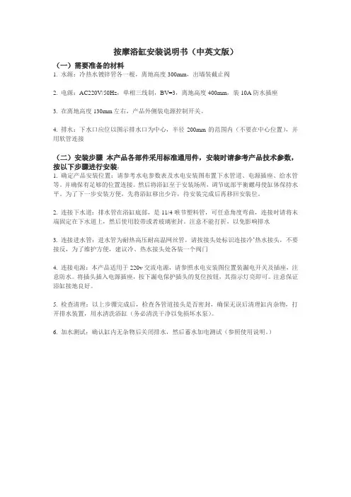
按摩浴缸安装说明书(中英文版)(一)需要准备的材料1. 水源:冷热水镀锌管各一根,离地高度300mm,出墙装截止阀2. 电源:AC220V/50Hz,单相三线制,BV=3,离地高度400mm,装10A防水插座3. 在离地高度130mm左右,产品外侧装电源控制开关。
4. 排水:下水口应位以图示排水口为中心,半径200mm的范围内(不要在中心位置),并用软管连接(二)安装步骤本产品各部件采用标准通用件,安装时请参考产品技术参数,按以下步骤进行安装:1. 确定产品安装位置:请参考水电参数表及水电安装图布置下水管道、电源插座、给水管等。
并确保有足够的位置连接。
然后将浴缸至于安装场所,调节底部平衡螺母使缸体保持水平。
为了下一步安装方便,先将浴缸移出少许,待安装完成后再移回安装位。
2. 连接下水道:排水管在浴缸底部,是11/4喉节塑料管,可任意角度弯曲,连接时请将末端固定在下水道上,然后使用胶带或者玻璃密封。
注意不能打折,以免影响排水3. 连接进水管:进水管为耐热高压耐高温网丝管,请按接头处标识连接冷‘热水接头,不要接反,为了维护方便,建议冷、热水接头处各装一个阀门4. 连接电源:本产品适用于220v交流电源,请参照水电安装图位置装漏电开关及插座,注意防水。
将插头插入电源插座,按下漏电保护插头的复位按钮,其指示灯亮即可。
注意保证浴缸接地良好。
5. 检查清理:以上步骤完成后,检查各管道接头是否密封,确保无误后清理缸内杂物,打开排水装置,用水清洗浴缸(务必清洗干净以免损坏水泵)。
6. 加水测试:确认缸内无杂物后关闭排水,然后蓄水加电测试(参照使用说明。
)Jacuzzi installation instructions (in English)(1) the need to prepare material1. Source: cold galvanization each a root, from the ground level 300 mm, the wall with globe valve2. Power: AC220V/frequency 50 Hz, single phase three wire, BV = 3, from the ground level 400 mm, with 10 A waterproof socket3. From ground level in 130 mm or so, the product with the power control switch.4. Drainage: buccal should be a drain on here as the center, the radius of the 200 mm range (don't in the center), and hose connection(2) the installation process This product components adopt standard part, when installation, please refer to the product technical parameters, according to the following steps to installation:1. Determine product installation position: please refer to the water and electricity parameter table and hydropower installation figure decorate water pipe, power outlets, pipes, etc. And to ensure enough position connection. Then will bath crock as for installation place, adjust the bottom to keep balance nut cylinder level. In order to the next step of convenient installation, the first move out of a bath crock, to install complete to move back to install a.2. Connections sewer: drain in bath crock bottom, is 1 throat section plastic pipe, can be arbitraryAngle bending, connection will be fixed in the sewers please end, then use adhesive tape or glass seal. Note can't discount, so as not to affect the drainage3. Connect feed line: feed line for heat resistant to high temperature high pressure pipe net silk, please click joints connected cold 'hot water mark joint, do not take the, in order to maintain convenient, the proposal within the cold and hot water to install a valve4. Connect the power: this product is suitable for 220 v ac power, please according to the installation drawing with electricity and water leakage switch and socket position, note waterproof. Insert the plug into the power supply socket, press the reset button leakage protection plugs, the indicator light can. Pay attention to ensure good bath crock grounding.5. Check the cleaning: the above steps after completion, check the pipe joints is sealed, make sure clear after the cylinder is sundry, open the drainage device, water to clean bath crock (be sure to clean in order to avoid damage the pump).6. Adding water test: confirmation without sundries in cylinder closed after drainage, then water storage, electric test (see instructions.)。
锅炉安装使用说明书Instruction For BoilerInstallationGA-SM7一、钢架和平台安装Installation for steel frame and platform 本篇适用于工作压力≤2.45Mpa(25kgf/cm2),蒸发量≤35t/h 的现场组装的工业锅炉的安装。
This paper is suitable to the boiler, which is going to be installed at site, with the working pressure less and equal to 2.45Mpa(25kgf/cm2)and steam capacity less and equal to 35t/h.1、基础的划线和验收以设计院提供的基础图为准,同时检查基础的标高尺寸、基础的表面和质量,以下表所示允差进行验收:The boiler foundation lineation acceptable shall be as per the foundation from designing institute. Check the elevation size and surface of foundation, allowable deviation for acceptance as below锅炉基础中心线与厂方基础中心线偏差20mmBoiler foundation centerline and user real foundationcenterline锅炉基础各不同标高的平面与设计标高差All different elevations for boiler foundation and designelevation+5-15mm锅炉基础外形几何尺寸±20mmBoiler foundation dimension2、基础上之垫铁不得超过三层。

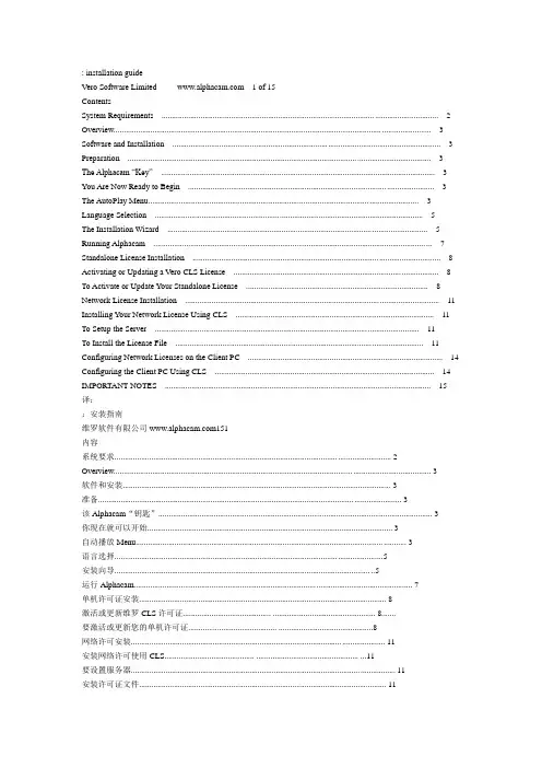
: installation guideVero Software Limited 1 of 15ContentsSystem Requirements (2)Overview (3)Software and Installation (3)Preparation (3)The Alphacam “Key” (3)You Are Now Ready to Begin (3)The AutoPlay Menu (3)Language Selection (5)The Installation Wizard (5)Running Alphacam (7)Standalone License Installation (8)Activating or Updating a Vero CLS License (8)To Activate or Update Your Standalone License (8)Network License Installation (11)Installing Your Network License Using CLS (11)To Setup the Server (11)To Install the License File (11)Configuring Network Licenses on the Client PC (14)Configuring the Client PC Using CLS (14)IMPORTANT NOTES (15)译::安装指南维罗软件有限公司151内容系统要求 (2)Overview (3)软件和安装 (3)准备 (3)该Alphacam“钥匙” (3)你现在就可以开始 (3)自动播放Menu (3)语言选择 (5)安装向导 (5)运行Alphacam (7)单机许可证安装 (8)激活或更新维罗CLS许可证........................................... .................................................. 8.......要激活或更新您的单机许可证........................................... . (8)网络许可安装 (11)安装网络许可使用CLS............................................ .................................................. (11)要设置服务器 (11)安装许可证文件 (11)配置网络许可证的客户端PC上........................................... .................................................. 14..配置客户端PC使用CLS (14)重要提示 (15): installation guideVero Software Limited 2 of 15System Requirements1.0GHz, 32 bit Intel Pentium compatible processor (2.0GHz Intel Pentium 4 or better recommended)Windows XP SP3 (XP Professional recommended), Windows Vista SP2 (Vista Business or VistaUltimate recommended), Windows 7 (Home, Professional or Ultimate recommended)Alphacam will install and run on the 'Home' editions of Windows XP and Windows Vista. However, thisis not recommended and we cannot guarantee to fix any Alphacam issues specifically related to these operating systems.Alphacam is not supported on Windows 7 Starter Edition.* Windows is a registered trademark of Microsoft Corporation in the United States and other countries1GB RAM (2GB or more highly recommended for 32-bit OS, 4GB for 64-bit OS)OpenGL® compatible with 64MB on-board memory (256MB or more recommended)1024x768 resolution (1280x1024 or higher recommended)Hard Disk Space1GB free hard disk space (minimum)DVD drive for software installation2 button,3 button, or 2 button with wheel (recommended) Windows compatible mouseUSB 1.1 or 2.0 port for single user security key supportTCP/IP required for network security support: installation guideVero Software Limited 3 of 15OverviewThis document contains step by step instructions and information on how to install the Alphacam software and CLS software licensing.Software and InstallationPreparationPlease make sure you read this entire document prior to installation of the Alphacam software.Before you start the installation process, it is recommended that you exit (close) all running applications. Closing all running applications prior to installing any new program will insure that you get a clean installation. The Alphacam “Key”译::安装指南Vero软件有限公司15 2系统要求处理器1.0GHz的32位英特尔奔腾兼容处理器(2.0GHz的英特尔奔腾4或推荐更好)操作系统的Windows XP SP3(XP专业版建议)中,Windows Vista SP2(Vista商业版或Vista终极推荐)时,Windows7(家庭版,专业版或旗舰版推荐)Alphacam将安装和运行在Windows XP和Windows Vista中的“家”的版本。
QF系列18~22MW汽轮发电机安装使用维护说明书MANUAL FOR18~22MW TURBO-GENERATOROF QF SERIES0JS・461・402 编制 TRANSLATOR: 刘红蕾 校核 CORRECTOR: 薛守栋 李 霖批准 APPROVER:时间D A T E: 2004.6山东济南发电设备厂SHANDONG JINAN POWER EQUIPMENT FACTORY THE PEOPLE’S REPUBLIC OF CHINA目录Content1.概述第 2 页General2.安装地点及使用条件第2 页Installation site and working conditions3.结构说明第 4 页Structure introduction4.安装说明第 12 页Installation5.使用说明第 18 页Operation6.维护检修说明第 26 页Maintenance7.无刷励磁机使用维护说明 第33 页Brushless Exciter type Operation and Maintenance Instruction 8.保证期第 40 页Guarantee period1. 概述本系列汽轮发电机为QF系列18~22MW空冷三相两极交流同步发电机,额定转速为3000r/min,频率为50Hz。
发电机设计为封闭循环通风系统,径向双流式通风系统。
发电机型号:如QF(NW)-18-2型,QF代表空冷汽轮发电机,18代表容量18兆瓦,2-代表2极,N 代表双支点,W代表无刷励磁方式。
本系列发电机有无刷励磁和静止励磁两种励磁方式供选择。
此系列汽轮发电机的旋转方向,从汽轮机端看为顺时针方向。
GeneralAll this series of Air-Cooled turbo-generators are three-phase, two-pole, synchronous generators whose powers range from 18 MW to 22 MW. Their rated speed and frequency are 3000r/min, 50Hz. The design of generators is closed and circular aeration system and radial double-flow aeration system. Generators model: For example QF(NW)-18-2, QF means Air-Cooled turbo-generators, 18 means Power is 18MW, 2 means 2 poles, N means two supports, W means Brushless Exciter type. This series of generators have two Exciter types, brushless exciter and static exciter. All this series of generators clockwise rotate when looking from driving-end.2. 安装地点及使用条件Installation site and working conditions:2.1 安装地点海拔不超过1000米。
IS型单级单吸清水离心泵INSTRUCTION FOR INSTALLATION ANDOPERATION OF TYPE IS PUMP 安装使用说明书Instruction On Installation And Operation湖南湘电长泵(长沙水泵厂)长一制泵有限公司ChangYi Pump Manufacturing Co.,Ltd. Of XiangDian ChangSha Pump Works目录CATALOGUE1、概述General2、结构说明Construction3、装配与拆卸Assembling and Dismantling4、安装Erection5、启动、停止与运转Starting, Shutdown and Running6、故障原因及其解决办法Probable Fault and Their Remedy1、概述IS型泵系单级单吸(轴向吸入)清水离心泵,适用于工业和城市给水、排水,亦可用于农业排灌。
供输送清水或物理及化学性质类似清水的其它液体之用。
温度不得高于80℃。
IS型泵系列性能范围(按设计点计)转速n:2900r/min和1450 r/min进口直径:50~200mm流量Q:6.3~400 mm扬程H:5~125 mmIS型系列泵型谱及主要性能参数见图2和表1。
型号说明,例如:IS80-65J-160AIS——单级单吸清水离心泵80——吸入口直径(㎜)65——排出口直径(㎜)J——表示降速使用160——叶轮名义直径(㎜)A——A、B、C叶轮直径经第一、二、三次切割2、结构说明IS型泵系根据国际标准IS02858所规定的性能和尺寸设计的,主要由泵体(1)、泵盖(2)、叶轮(3)、轴(4)、密封环(5)、轴套(6)及悬架轴承部件(12)等所组成(图1)。
IS型泵的泵体和泵盖是从叶轮背面处剖分的,即通常所说的后开门结构形式。
其优点是检修方便,检修时不动泵体、吸入管路、排出管路和电动机,即可退出转子部件进行维修。
JS-5A0全自动工业缝纫机伺服控制器AUOMATIC INDUSTRIAL SEWING MACHINE SERVO CONTROLLER安装使用说明INSTRUCTION MANUAL BOOK前言感谢您选用本公司的工业缝纫机伺服控制器。
本手册提供了使用该系统所需知识及注意事项。
l为了您更好地使用该产品,有使用之前请仔细阅读本手册。
您在使用中若有任何疑问或对我们的产品和服务有任何意见,请随时与我们联系。
主要技术数据供电电压范围:单相AC200V~AC240V±10%供电电源频率:50Hz/60Hz整机最大功率:700W电机额定功率:550W电机额定转速:6000rpm电机额定扭矩:0.6 N·m电机最大扭矩:1.8 N·m目录1 安全注意事项.........................................................................................................................- 1 -1.1 使用范围......................................................................................................................- 1 -1.2 工作环境:..................................................................................................................- 1 -1.3 注意事项......................................................................................................................- 1 -1.4 保养维修......................................................................................................................- 1 -1.5 危险提示......................................................................................................................- 1 -1.6 接线与接地..................................................................................................................- 2 -1.7 其它安全规定..............................................................................................................- 3 -2. 脚踏速控器前后踏力量的调整.............................................................................................- 3 -3. 操作面板说明........................................................................................................................- 4 -3.1基本框图.......................................................................................................................- 4 -3.2按键定义.......................................................................................................................- 4 -3.3按键操作.......................................................................................................................- 6 -3.4基本功能.......................................................................................................................- 8 -3.5指示灯...........................................................................................................................- 9 -3.6界面显示.....................................................................................................................- 10 -4. 参数说明..............................................................................................................................- 11 -4.1 包缝参数表(一区U)................................................................................................- 11 -4.2 包缝参数表(二区U.)...............................................................................................- 15 -4.3 工艺参数表................................................................................................................- 16 -5. 故障分析..............................................................................................................................- 18 -5.1 故障表........................................................................................................................- 18 -6. 接口及接线图......................................................................................................................- 20 -6.1接口板连接线及接口图(附图)..............................................................................- 20 - JIJU布边传感器.......................................................................................................................- 21 -7.1JIJU布边传感器外形..................................................................................................- 21 -1 安全注意事项1.1 使用范围本伺服控制器及其电机是专为工业缝纫机开发设计的,如果在其它方面使用,请注意使用者的安全。
S型单级双吸离心泵安装使用说明书Instruction of Installation & OperationforType S Single -stage Double -suction Centrifugal Pump 长沙水泵厂有限公司Changsha Pump Works Co., Ltd.二OO七年十一月Nov, 2007一.概述GeneralS型泵系单级、双吸、水平中开式卧式离心泵,供输送不含固体颗粒的清水或物理、化学性质类似于清水的其它液体,被输送介质的温度为0℃~80℃,允许进口压力为0.6MPa,适用于工厂、城市、电站、农田、水利工程等领域的给排水用泵。
Type S pump belongs to single-stage double-suction split centrifugal pump. It transfers clear water or pure liquids physically and chemically similar to clear water. The temperature of the liquid is 0 o C~80 o C. Permissible maximum inlet pressure is 0.6 MPa. They are widely used for water supply & drainage in fields of factories, cities, mines, power stations and farmlands as well as water conservancy.型号说明:例 300S58A300-表示泵吸入口直径(mm)。
S-表示单级、双吸、中开式离心泵。
58-泵设计扬程(m)。
A-泵的叶轮外径或泵的转速改变标志。
Type description, for example: 300S58A300----Inlet diameter is 300mm)S----Single-stage, double-suction centrifugal pump58----Head at design pointA----The working performances change after the impeller is cut or the speed decreases, but the other dimensions don’t change.泵的过流部件材质为铸铁。
Enclosure Climate Control Unit工业控制柜制冷机Assembly Instructions安装说明书(ECC 系列)内容1.应用场合2.技术参数3.安装方式4.安全与注意5.电气连接6.常规操作7.工作原理8.维护保养9.质量保证10.电气原理图11.安装尺寸图1.应用场合工业控制柜制冷机通过把控制柜的空气冷却同时把柜内热量驱散出柜外,从而保护控制柜内的电气元件在可控的范围内运行。
制冷机同时具有除湿功能,保证控制柜内有理想的温度和湿度。
2.技术参数壁装系列型号 ECC225ECC320 ECC680 ECC825设计电压VAC/ Hz230/50可用制冷功率W(L35 L30)225 320 680 825外形尺寸(H×W×D)mm445×286×181 630×350×190 制冷剂 R134a环境温度/可调节范围(℃) 20~55 / 20~38重量(Kg) 15 16 26 28型号 ECC1100ECC1500设计电压VAC/ Hz230/50可用制冷功率W(L35 L30)1100 1500外形尺寸(H×W×D)mm400×1000×240制冷剂 R134a环境温度/可调节范围(℃) 20~55 / 20~38重量(Kg) 38 41顶装系列型号 ECC680T ECC1100T ECC1500T设计电压VAC /Hz230/50可用制冷功率W680 1100 1500外形尺寸(H×W×D)mm350×527×335 410×608×427制冷剂 R134a R22环境温度/可调节范围(℃) 20~55 / 20~38重量(Kg) 26 36 403.安装方式根据产品的型号,制冷机可以有壁装,顶装,两种安装方式,开孔图详见下面的安装尺寸图3.1外挂式按照开孔图开孔,把相应型号的制冷机用随附的螺钉先安装到控制柜上,使用制冷机后面的内六角螺钉与控制柜锁紧。
3.2顶装按照开孔图开孔, 再锁紧制冷机底部内置的螺丝孔保证制冷机与控制柜的固定与密封。
4.安全与注意安全提示¾制冷机为精密电气,搬运务必轻放,严禁倒置,倾斜存放。
¾妥善处理制冷机的冷凝水,标准配置有制冷机的出水管及连接螺母。
注意事项¾制冷机在灰尘大,或油性,毛绒的环境务必及时清理过滤网,否则会影响制冷机性能。
¾制冷机入风口需安装到控制柜体的上部。
¾控制柜外的温度不能超过55摄氏度,但短暂的高温并不影响制冷机运作。
¾包装应完好,如果发现制冷机有油渍,极有可能是泄漏制冷剂,包装的任何损坏都有可能引起制冷机的故障。
¾控制柜必须达到IP54,如果控制柜有漏洞或缝隙,冷凝水可能会发生。
¾制冷机之间或制冷机与墙壁距离至少不小于200mm¾在控制柜内部,制冷机入风和出风口不可有障碍物阻塞。
¾制冷机需水平安装、使用,最大倾斜角度不大于2°¾维护及送电必须由专业人员操作。
¾为避免冷凝物的形成,建议采用门位开关,保证当控制柜门打开时,制冷机处于关闭状态。
¾控制柜内部的电气元件的热释放不能超过制冷机可用制冷功率,否则会出现制冷机长期运作。
¾不可用任何方式修改制冷机。
5.电气联接电压与频率必须与制冷机的铭牌相匹配,在制冷机电气联接前端不可有其他的温度控制,制冷机上回路电保护元件应与制冷机额定功率相吻合,在安装时参考相关说明。
三相制冷机建议采用马达保护器。
特殊电压请参照相关手册安装使用。
6.常规操作在连接电源后,打开总开关,蒸发风机会一直运转,保证控制柜内部的空气流动,避免热积累。
制冷机温控器出厂已经设定为35度,(建议使用出厂设定),制冷机根据设定温度自动开闭制冷压缩机运作。
制冷机过滤网有金属过滤网及PU 高分子过滤网两种(标准供货为金属过滤网)由于外循环风机足够的风量和风压,细微尘粒被直接吹过,不影响制冷机运作。
金属过滤网用于抵御大颗粒灰尘,及油污和毛绒性环境,7.工作原理制冷机采用相变制冷原理,从压缩机内排出的高温高压气态制冷剂进入冷凝器,被强制冷却为高压中温的液态制冷剂,经毛细管或膨胀阀节流后变成低温低压的液态制冷剂,进入到蒸发器,通过相变吸收控制柜内的热量后变成气态再进入压缩机,往复循环保证控制柜的可靠工作环境。
壁装系列EnglishContents1. Applications2. Technical Date3. Mounting Instructions4. Safety and Attentions5. Electrical Connection6. Routine operation7. Working Theory8. Maintenance9. Quality Guarantee10. Wiring Diagram11. Mounting Diagram1. ApplicationEnclosure Climate Control Units are designed and built to dissipate heat from enclosures by cooling the air inside the enclosure and protecting temperature-sensitive components working in the expected temperature and humidity.2. Technical DateVertical-mounted SerialType ECC225ECC320ECC680Rated operating Voltage( VAC/Hz) 230/50Useful cooling output(W) 225 320 680Dimension in mm(H×W×D)445×286×181 630×350×190 Refrigerant R134aTemperature range(°C)20~55Weight(Kg)15 16 26Top-mounted SerialType ECC680T ECC1100T ECC1500TRated operating Voltage( VAC/Hz) 230/50Useful cooling output(W) 680 1100 1500Dimension in mm(H×W×D)350×527×335 410×608×427Refrigerant R134a R22 Temperature range(°C)20~55Weight(Kg)26 36 403. Mounting InstructionsAccording to production model, the unit can be vertical-mounted, top-mounted, horizontal-mounted, there into vertical-mounted, top-mounted units also can be external installed, or partially installed to chioce. Cut out the sections and drill according to mounting diagram as below.3.1 external installedCut the enclosed seals to the required length and attach to the unit in accordance with mounting diagram, Screw the bolt into the blind nuts on the rear of the unit.3.3 top-mountedCut the enclosed deals to the required length according to the mounting diagram, Screw the bolt into the blind nuts on the bottom of the unit.4. Safety and AttentionsSafety NoticesThe following safety notices are to be observed in their entirety for the correct use of equipment.¾To prevent the enclosure with the climate control unit fitted tipping over. It is essential that this be bolted to the floor.¾Take the condensate drainage of the units into account with scientific way, the water pipe is backup for the safety.Attention Notices¾The location is free from excessive dirt and moisture, greasy environment. The filter net should be cleaned in time otherwise the performance of the unite will be lower.¾The cutout for air extraction is located in the upper area of the enclosure.¾The ambient temperature does not exceed +55°C, but the temporary high temperature is acceptable.¾The packaging shows no signs of damage. Traces of oil on damaged packaging are an indication of refrigerant loss and of leakage in the unit system. Any damage to the packaging may be the cause of subsequent malfunctions;¾the enclosure is sealed on all sides (IP 54). Condensation will occur if the enclosure is leaky.¾The separation of the units from one another and from the wall should not be less than 200 mm.¾Air inlet and outlet are not obstructed on the inside of the enclosure.¾Units are only fitted horizontally in the specified position. Max. deviation from the true horizontal: 2°.¾Electrical connection and repair are carried out only by authorized person. Use only original replacement parts!¾To avoid an increase in condensation, a door operated switch should be used which will switch the cooling unit off when the enclosure door is opened.¾losses from the components installed in the enclosure must not exceed the specific refrigeration capacity of the cooling unit itself, otherwise the units will working all the time.¾the customer must not modify the cooling unit in any way.5. Electrical ConnectionThe connected voltage and frequency must correspond to the values stated on the rating plate. During commissioning, the data on the rating plate of the device shall apply. The unit must not have any additional temperature control connected up-stream at the supply end. Line protection should be provided by means of the pre-fuse specified on the rating plate. Observe the relevant regulations during installation!The three phase supplies are to be connected via a motor safety switch to a TN grid with grounded star point.Specially rated units, which are also fitted with a transformer, standard motor safety switches no longer suffice due to their switching characteristics. Therefore transformer safety switches must be installed on the customer side. These are to be set to the rated current given on the nameplate.For units designed for three phase 400/460 V, the rotary field or the absence of a phase must be monitored. If the rotary field is incorrect or a phase is absent, the unit will not run.6. Routine operationAfter electrical connection, switch on the main breaker of the unit, the evaporator fan will run continuously to circulate the air inside the enclosure. The installed basic controller (setting the desired internal temperature, factory setting +35°C ) provides automatic control switch-off of the cooling unit by the set value of the fixed switching difference of 5 K..Fault signal relay with changeover contact Terminal 12 and Terminal 13 NC (normally closed), this is function is Supplementary functions. As a result, the relay contacts change their state representing the normal operating status of the cooling unit. As soon as a system message occurs or the voltage supply is interrupted, the relay drops out. (see also circuit diagrams ).The PU foam filter mat available as an accessory is coarse and filters large dust particles or fluff from the air. Metallic filter mats are used to trap oil condensate. These are also available as an accessory. Subject to the suction of the blower being high enough, fine dust is blown through the filter mat and the external circuit of the unit. This does not affect the unit's operation..7. Working TheoryThe compressor takes the gaseous refrigerant from the evaporator and compresses it to a higher pressure in the condenser. During this process the temperature of the refrigerant rises above the ambient temperature and heat can be dissipated to the environment via the surface of the condenser. Then the refrigerant is liquefied and by means of a thermostatically controlled expansion valve, returned to the evaporator, where it evaporates at low pressure. The heat required for complete evaporation is drawn from the enclosure interior causing it to cool down. The cooling cycle is thus completed, the aforementioned process of the heat transfer starts afresh.8. MaintenanceAs a maintenance-free, hermetically sealed system, the cooling circuit has been filled in the factory with the required amount of refrigerant, and tested for leaks and subjected to a function trial run. The installed maintenance-free fans use ball bearings; they are protected against moisture and dust, and are fitted with a temperature monitor. The life expectancy is at least 30,000 operating hours. The cooling unit is thus largely maintenance free. All that may be required from time to time is that the components of the external air circuit are cleaned by compressed air.The use of a filter mat is recommended only if large particles of lint are present in the air, so that blockage of the condenser is prevented.Prior to any maintenance work, the power to the cooling unit must be disconnected.9. Quality GuaranteeThis unit is covered by a 1-year guarantee from the date of supply, subject to correct usage (See also Safety notices ).Within this period, the returned unit will be repaired in the factory or replaced free of charge.The cooling unit is to be used for the cooling of enclosures only. If it is connected or handled improperly the manufacturer’s guarantee does not apply and in this case we are not liable for any damage caused. 10. Wiring Diagram(Re. Chinese Version)11. Mounting Diagram(Re. Chinese Version)。