FM-E31光纤传感器使用说明
- 格式:pdf
- 大小:4.87 MB
- 文档页数:6

Wenglor(威格勒)光纤传感器调整使用说明(中文)1.控制1.1控制面板01.状态指示02.污染报警07.选择开关24.加按钮25.减按钮2.调整2.1延迟接通和延迟断开调整延迟接通和延迟断开延迟加按钮减按钮Gelbe 状态LED0ms 灯亮灯不亮灯不亮10ms 灯不亮灯不亮闪1下,间歇,闪1下20ms 灯不亮灯不亮闪2下,间歇,闪2下。
200ms 灯不亮灯亮闪20下,间歇,闪20下调整延迟接通调整延迟断开设置旋转选择器开关(07)在延迟接通设置旋转选择器开关(07)延迟断开激活加号按钮(24)。
延迟增加10 ms激活负按钮(25)。
延迟减少10 ms设置旋转选择器开关(07)来运行2.2选择常闭或常开功能设置旋转选择器开关(07)在常闭/常开(PNP / NPN型)激活加号按钮(24)NC是选定的(常闭/暗开关)---加号按钮(24)点亮---激活负按钮(24)NO是被选中(常开/光开关)---减去按钮(24)点亮设置旋转选择器开关(07)来运行2.3选择PNP / NPN 模式设置旋转选择器开关(07)NC/NO PNP / NPN模式激活加号按钮(24)为5秒---加号按钮(24)和负按钮(25)闪烁释放加号按钮(24)激活加号按钮(24)---加号按钮(24)点亮---PNP型设置激活负按钮(25)---减去按钮(25)点亮----NPN型设置同时激活加号按钮(24)和负按钮(25)加号按钮(24)和负按钮(25)点亮Push-pull setting 设置旋转选择器开关(07)来运行2.4设置开关距离与电位计设置旋转选择器开关(07)电位计激活加号按钮(24)---开关距离增加激活负按钮(25)---开关距离减少加减按钮上的LED的亮度指示加减的程度、相对应的的按钮越亮,感应距离越大,反之亦然。
如果最大值或最小值传感距离被选中相应的按钮会闪烁。
设置旋转选择器开关(07)来运行2.5用自学习功能设置开关距离用自学习功能设置理想的开关感应距离2.5.1标准模式设置旋转选择器开关(70)----红色LED(02)点亮适当放置目标对象激活加号按钮(24)---加号按钮(24)点亮激活加号按钮(24)再次*---加号按钮(24)不再是明亮的设置旋转选择器开关(07)来运行*如果在40秒内第二个按钮没有被操作,自学习过程被取消并不保存任何设置2.5.2Minimal Teach-In设置旋转选择器开关(07)适当放置目标对象激活减号按钮(25)---减号按钮(25)点亮激活减按钮(25)再次*---减号按钮(25)不再是明亮的设置旋转选择器开关(07)来运行The contamination warning is out of order during minimal Teach-In2.5.3Dynamic Teach-In (Teach-In with moving objects)设置旋转选择器开关(07)按下并保持住(约5秒)加号按钮(24)直到(24)闪烁---传感器是现在在记录模式,获得最小和最大入射光信号激活加号按钮(24)再次---记录模式是结束---加号按钮(24)不再是明亮的设置旋转选择器开关(07)来运行在自学习模式时传感器不会输出扫描和屏障模式在记录模式时,传感器根据入射光信号的最小和最大值之间自动确定理想的开关点。
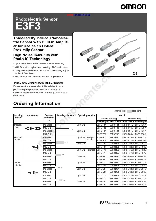
on e n t s .co mE3F3 Photoelectric Sensor1Threaded Cylindrical Photoelec-tric Sensor with Built-in Amplifi-er for Use as an Optical Proximity SensorHigh Noise-immunity with Photo-IC Technology•Up-to-date photo-IC to increase noise immunity.•M18 DIN-sized cylindrical housing, ABS resin case.•Long sensing distance (30 cm) with sensitivity adjus-tor for diffuse type.•Short-circuit and reverse connection protection.<READ AND UNDERSTAND THIS CATALOG>Please read and understand this catalog before purchasing the products. Please consult yourOMRON representative if you have any questions or comments.Ordering Informationo nl i ne c om p on e n t s .co m2E3F3 Photoelectric Sensor■Model Number Legend■Accessories (Order Separately)Note:E39-R1 is included in E3F3-R @@ and E3F3-R @@M.Specifications■Ratings/CharacteristicsNameModelReflectorE39-R1, E39-R3Reflector (tape type)E39-RS1, E39-RS2, E39-RS3Lens Cap E39-F31Mounting BracketY92E-B18ItemSensing method Through-beam RetroreflectiveDiffuse reflectiveNPN outputE3F3-T11E3F3-R11E3F3-R12E3F3-D11E3F3-D12E3F3-T16E3F3-R16E3F3-R17E3F3-D16E3F3-D17E3F3-T61E3F3-R61E3F3-R62E3F3-D61E3F3-D62E3F3-T66E3F3-R66E3F3-R67E3F3-D66E3F3-D66PNP outputE3F3-T31E3F3-R31E3F3-R32E3F3-D31E3F3-D32E3F3-T36E3F3-R36E3F3-R37E3F3-D36E3F3-D37E3F3-T81E3F3-R81E3F3-R82E3F3-D81E3F3-D82E3F3-T86E3F3-R86E3F3-R87E3F3-D86E3F3-D87Sensing distance 5 m3 m (Non-polarized when us-ing E39-R1) 2 m (Non-polarized when us-ing E39-R1)100 mm 300 mmStandard sensing object Opaque object: 11mm min.Opaque object: 56mm min.100 × 100 mm white mat paperHysteresis---20% max. of sensing distanceLight source (wavelength)Infrared LED (860 mm)Red LED (680 mm)Infrared LED (860 mm)Power supply voltage 12 to 24 VDC ±10%, ripple (p-p): 10% max.Current consumption 45 mA max. (light source and receiver)25 mA max.Control output Open collector transistor output, 100 mA max., residual voltage: 1 V max. at 100 mA Protective circuit Output short-circuit protection, DC power supply reverse polarity protection Response time 1.0 ms max.Sensitivity adjustment ---Single-turn adjusterAmbient illumination Incandescent lamp: 3,000 l x max., Sunlight: 10,000 l x max.Ambient temperature Operating: –25 to 55 °C (with no icing or condensation)Storage: –30 to 70 °C (with no icing or condensation)Ambient humidity Operating: 45% to 85% (with no condensation)Storage: 35% to 95% (with no condensation)Insulation resistance 20 M Ω min. (at 500 VDC) between current carry parts and case Dielectric strength 1,000 VAC at 50/60 Hz for 1 min between current carry parts and case Vibration resistance (destruction)10 to 55 Hz, 1.5-mm double amplitude for 1 hour each in X, Y , and Z directions Shock resistance (destruction)500 m/s 2 for 3 times each in X, Y , and Z directionsDegree of protection IEC 60529 IP66Connecting method Pre-wired (standard length: 2 m)/M12 connectorIndicatorsOperation indicator (orange) [Power indicator of emitter (orange)]Weight Pre-wiredMetal: 200 g max.Metal housing: 100 g max.Plastic: 170 g max.Plastic housing: 85 g max.M12 connectorMetal: 120 g max.Metal housing: 60 g max.Plastic: 40 g max.Plastic housing: 20 g max.Packing Nylon bag MaterialCase Plastic: ABS, Metal: Nickel-brass Lens PMMAAccessoriesScrew nuts: ABS or Nickel-brassAccessoriesScrew nuts (4),Instruction sheetScrew nuts (2),E39-R1 reflector,Instruction sheetScrew nuts (2),Instruction sheetScrew nuts (2),Instruction sheet,Adjusting driverE3F3 Photoelectric Sensor3Engineering Datai m4E3F3 Photoelectric SensorOperation■NPN Output■PNP Outputo e c .co E3F3 Photoelectric Sensor5DimensionsNote:All units are in millimeters unless otherwise indicated.■SensorsNote:Pre-wired Cord:Polyvinyl chloride-covered cord, 4-mm dia. (18/0.12), Standard length: 2 mEmitter: 2-conductor (brown and blue)Receiver and Reflective model: 3-conductor (brown, blue, and black)M12 connector: 1: +V, 2: NC, 3: 0 V, 4: Output2422E3F3-D @249.442.43724E3F3-D @2M422E3F3-D @724E3F3-D @7M2224E3F3-R @2E3F3-D @1247.7E3F3-R @1M E3F3-R @2M E3F3-D @1M2224E3F3-D @62427.7E3F3-D @6Mo nl i ne c om p on e n t s .co m6E3F3 Photoelectric Sensor■Accessories (Order Separately)E39-R3 RetroreflectorE39-RS1 RetroreflectorE39-RS2 Retroreflector1134.819.3T wo, M32.61.2343841.810.125.4+0.11.2T wo, M30.220381.210534R25.416T wo, 3.2 dia.11200.20.214513.7293.4R204.53.4718.4562822.93.4Adhesiveside 25.4Mounting Bracket for E39-K3(Sold Together)E39-RS3 RetroreflectorAdhesive tape sideAdhesive tape sideAdhesive tape sideMaterial: Acrylic resinMaterial: Acrylic resinMaterial: Acrylic resino nl i ne c om p on e n t s .co mE3F3 Photoelectric Sensor7PrecautionsIf the input/output lines of the photoelectric sensor are placed in the same conduit or duct as power lines or high-voltage lines, the photo-electric sensor could be induced to malfunction, or even be dam-aged, by electrical noise. Separate the wiring, or use shielded lines as input/output lines to the photoelectric sensor.Do not subject the photoelectric sensor to excessive shock when mounting, in keeping with IP66 standards.When you use the photoelectric sensor in the vicinity of an inverter motor, be sure to connect the protective ground wire of the motor to ground. Failure to ground the motor may result in malfunction of the sensor.MountingDo not exceed a torque of 20 kgf·cm (2.0 N·m) when tightening mounting nuts.!WARNINGThe E3F3 Photoelectric sensor is not a safety component for en-suring the safety of people as defined by EC Directives (91/386EEC) and covered by separate European standards or by any oth-er regulations or standards.E39-F31 Lens Cap32+0.217 max.718 dia.3047 max.4 max.o nl i ne c om p on e n t s .co mREAD AND UNDERSTAND THIS DOCUMENTPlease read and understand this document before using the products. Please consult your OMRON representative if you have any questions or comments.WARRANTYOMRON’s exclusive warranty is that the products are free from defects in materials and workmanship for a period of one year (or other period if specified) from date of sale by OMRON.OMRON MAKES NO WARRANTY OR REPRESENTATION, EXPRESS OR IMPLIED, REGARDING NON-INFRINGEMENT, MERCHANTABILITY, OR FITNESS FOR PARTICULAR PURPOSE OF THE PRODUCTS. ANY BUYER OR USER ACKNOWLEDGES THAT THE BUYER OR USER ALONE HAS DETERMINED THAT THE PRODUCTS WILL SUITABLY MEET THE REQUIREMENTS OF THEIR INTENDED USE. OMRON DISCLAIMS ALL OTHER WARRANTIES, EXPRESS OR IMPLIED.LIMITATIONS OF LIABILITYOMRON SHALL NOT BE RESPONSIBLE FOR SPECIAL, INDIRECT, OR CONSEQUENTIAL DAMAGES, LOSS OF PROFITS OR COMMERCIAL LOSS IN ANY WAY CONNECTED WITH THE PRODUCTS, WHETHER SUCH CLAIM IS BASED ON CONTRACT, WARRANTY , NEGLIGENCE, OR STRICT LIABILITY .In no event shall responsibility of OMRON for any act exceed the individual price of the product on which liability is asserted.IN NO EVENT SHALL OMRON BE RESPONSIBLE FOR WARRANTY , REPAIR, OR OTHER CLAIMS REGARDING THE PRODUCTS UNLESS OMRON’S ANALYSIS CONFIRMS THAT THE PRODUCTS WERE PROPERLY HANDLED, STORED, INSTALLED, AND MAINTAINED AND NOT SUBJECT TO CONTAMINATION, ABUSE, MISUSE, OR INAPPROPRIATE MODIFICATION OR REPAIR.SUITABILITY FOR USETHE PRODUCTS CONTAINED IN THIS DOCUMENT ARE NOT SAFETY RATED. THEY ARE NOT DESIGNED OR RATED FOR ENSURING SAFETY OF PERSONS, AND SHOULD NOT BE RELIED UPON AS A SAFETY COMPONENT OR PROTECTIVE DEVICE FOR SUCH PURPOSES. Please refer to separate catalogs for OMRON's safety rated products.OMRON shall not be responsible for conformity with any standards, codes, or regulations that apply to the combination of products in the customer’s application or use of the product.At the customer’s request, OMRON will provide applicable third party certification documents identifying ratings and limitations of use that apply to the products. This information by itself is not sufficient for a complete determination of the suitability of the products in combination with the end product, machine, system, or other application or use.The following are some examples of applications for which particular attention must be given. This is not intended to be an exhaustive list of all possible uses of the products, nor is it intended to imply that the uses listed may be suitable for the products:•Outdoor use, uses involving potential chemical contamination or electrical interference, or conditions or uses not described in this document.•Nuclear energy control systems, combustion systems, railroad systems, aviation systems, medical equipment, amusement machines, vehicles, safety equipment,and installations subject to separate industry or government regulations.•Systems, machines, and equipment that could present a risk to life or property.Please know and observe all prohibitions of use applicable to the products.NEVER USE THE PRODUCTS FOR AN APPLICATION INVOLVING SERIOUS RISK TO LIFE OR PROPERTY WITHOUT ENSURING THAT THE SYSTEM AS A WHOLE HAS BEEN DESIGNED TO ADDRESS THE RISKS, AND THAT THE OMRON PRODUCT IS PROPERLY RATED AND INSTALLED FOR THE INTENDED USE WITHIN THE OVERALL EQUIPMENT OR SYSTEM.PERFORMANCE DATAPerformance data given in this document is provided as a guide for the user in determining suitability and does not constitute a warranty. It may represent the result of OMRON’s test conditions, and the users must correlate it to actual application requirements. Actual performance is subject to the OMRON Warranty and Limitations of Liability.CHANGE IN SPECIFICATIONSProduct specifications and accessories may be changed at any time based on improvements and other reasons.It is our practice to change model numbers when published ratings or features are changed, or when significant construction changes are made. However, some specifications of the product may be changed without any notice. When in doubt, special model numbers may be assigned to fix or establish key specifications for your application on your request. Please consult with your OMRON representative at any time to confirm actual specifications of purchased products.DIMENSIONS AND WEIGHTSDimensions and weights are nominal and are not to be used for manufacturing purposes, even when tolerances are shown.ERRORS AND OMISSIONSThe information in this document has been carefully checked and is believed to be accurate; however, no responsibility is assumed for clerical, typographical, or proofreading errors, or omissions.PROGRAMMABLE PRODUCTSOMRON shall not be responsible for the user’s programming of a programmable product, or any consequence thereof.COPYRIGHT AND COPY PERMISSIONThis document shall not be copied for sales or promotions without permission.This document is protected by copyright and is intended solely for use in conjunction with the product. Please notify us before copying or reproducing this document in any manner, for any other purpose. If copying or transmitting this document to another, please copy or transmit it in its entirety.In the interest of product improvement, specifications are subject to change without notice.ALL DIMENSIONS SHOWN ARE IN MILLIMETERS.To convert millimeters into inches, multiply by 0.03937. T o convert grams into ounces, multiply by 0.03527.Cat. No. E365-E1-01OMRON CorporationIndustrial Automation CompanySensing Devices Division H.Q.Industrial Sensors Division Shiokoji Horikawa, Shimogyo-ku,Kyoto, 600-8530 JapanT el: (81)75-344-7022/Fax: (81)75-344-7107Printed in Japan 0605-?M (0605) (?)。
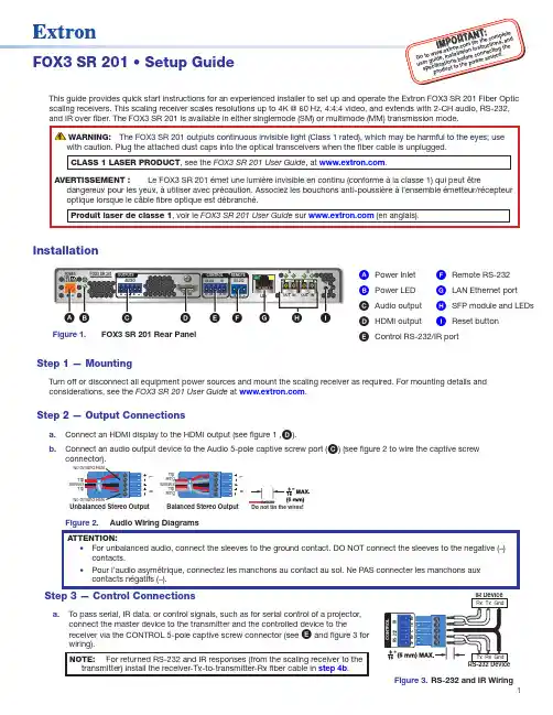
1I M P O .e x t r o n .c o m f o r t i o ni n s t r u c ti on s ,e c t i n g t h eFOX3 SR 201 • Setup GuideThis guide provides quick start instructions for an experienced installer to set up and operate the Extron FOX3 SR 201 Fiber Opticscaling receivers. This scaling receiver scales resolutions up to 4K @ 60 Hz, 4:4:4 video, and extends with 2-CH audio, RS-232, and IR over fiber. The FOX3 SR 201 is available in either singlemode (SM) or multimode (MM) transmission mode.InstallationREMOTEPOWER 12V2.0A MAXA OUT IN BOUT INLANHDMIFOX3 SR 201RAUDIOCONTROLOUTPUTSIG F C A D H E BFigure 1.FOX3 SR 201 Rear PanelA Power Inlet F Remote RS-232B Power LED G LAN Ethernet portC Audio output H SFP module and LEDsD HDMI output I Reset buttonE Control RS-232/IR portStep 1 — MountingTurn off or disconnect all equipment power sources and mount the scaling receiver as required. For mounting details and considerations, see the FOX3 SR 201 User Guide at .Step 2 — Output Connectionsa. D ).b. C ) (see figure 2 to wire the captive screwUnbalanced Stereo OutputBalanced Stereo Output LRLRa. To pass serial, IR data, or control signals, such as for serial control of a projector,connect the master device to the transmitter and the controlled device to thereceiver via the CONTROL 5-pole captive screw connector (see E and figure 3 for wiring).Figure 3. RS-232 and IR Wiring2FOX3 SR 201 • Setup Guide (Continued)b. For remote control of a unit and loading firmware (LAN or USB only), connect a host device, such as a computer or controlsystem, to one of the following ports (see the FOX3 SR 201 User Guide , available at , for details):•Remote RS-232 port — Connect the 3-pole captive screw connector to this port (F ). The protocol for the Remote port is as follows:• 9600 baud • no parity • 8 data bits • 1 stop bit • no flow control• LAN Ethernet port — Connect an RJ-45 connector to this port (G ).•USB Configuration port — Connect a USB mini-B connector to this port (see figure 5, B on page 2).Step 4 — Throughput Connections).b. to the transmitter, connect a cable between the A Out port on the receiver and A In port on the transmitter (2).c. To transmit an uncompressed 4K @ 60 Hz signal, using the Uncompressed Video LinkLicense,repeat step 4a on the SFP B port on the scaling receiver SFP Link LEDs — ReceiverFigure 4.Fiber Cable Connection• Transmit Optical OUT LED — Lights solid green when powered and lights off when there is no power on the endpoint.•Receive Optical IN LED — Lights solid green when light is present and lights off when there is no power or light present.Step 5 — Power ConnectionConnect the included external 12 VDC power supply into the 2-pole connector (see figure 1, A on page 1). The power LED lights (B ) when the unit is receiving power.OperationAfter the receiver, transmitter, and their connected devices are powered up, the system is fully operational. If any problems are encountered, verify that the cables are routed and connected properly and the display device has a compatible resolution and refresh rate. If problems persist, call the Extron S3 Sales & Technical Support Hotline (see the contact number on page 6).FOX3 SR 201MENUINPUTSIGNAL HDCPENTER C AD EB Figure 5.FOX3 SR 201 Front PanelA Power LED — Indicates power is applied to the unit.B USB Config port — Connect a USB Mini-B cable to a computer to configure the device and update the firmware via ProductConfiguration Software (PCS), Simple Instruction Set (SIS) commands, or internal web pages.C Input LEDs —• Signal LED — Lights when the unit detects an input video signal.•HDCP LED — Lights when the input signal is HDCP encrypted.D Menu and Enter buttons — Press these buttons to access and navigate the on-screen display menu system.E Navigation buttons — Press these buttons to navigate through the on-screen display menu system or change settings. ResetPress the rear panel recessed reset button (see figure 1, I on page 1) if the FOX3 scaling receiver firmware is corruptedor the unit gets disconnected during the update process. The different resets allow the device to revert to the factory loaded firmware, reset IP seetings, or reset configuration to default (see the Reset Modes table, for details on the reset modes).Front Panel Lockout Mode (Executive Mode)The front panel lockout mode limits operation of the device from the front panel. When enabled, use SIS commands or the Product Configuration Software (PCS) to configure the device. To enable or disable the front panel lockout mode through the front panel, press and hold the Menu (see figure 5, D on page 2) and down arrow (E) buttons simultaneously for 5 seconds oruntil the power LED blinks.34FOX3 SR 201 • Setup Guide (Continued)Configuration and ControlTo configure the FOX3 SR, use the front panel controls and the on-screen display (OSD) menu, Simple instruction Set (SIS) commands, or PCS.On-screen display menu systemThe OSD menu consists of two submenus, Device Info and Setup , that can be accessed using the front panel Menu button. View the menu on a display connected to the HDMI output connector (see figure 1, D on page 2). The Device Info submenu is view only. The following fields can be configured from the Setup submenu:•Output Rate — Select from a list of refresh rates (see Output Resolution table on page 5). The default setting is 1080p @ 60 Hz.•HDMI Format — Select the output format:• Auto (default)• DVI RGB 444• HDMI RGB 444 Full • HDMI RGB 444 Limited • HDMI YUV 444 Full • HDMI YUV 444 Limited • HDMI YUV 422 Full •HDMI YUV 422 Limited• Test Pattern — Select an available test pattern to display or turn a test pattern off. The available test pattern selections are Crop, Alternating Pixels, Crosshatch, and Color Bars. The default setting is Off.•Factory Reset — Reset the unit to its factory default values (removing any user-specified values) while retaining all TCP/IP settings.To adjust settings:1. Press the Menu button to access the main menu.2. Press the directional arrows to navigate to a desired submenu.3. Press the Enter button to access submenu items of a selected submenu.4. Press the directional arrows to navigate a desired submenu item.5. Press the Enter button to select a submenu item for adjustment.6. As required, press the directional arrows or press the Enter button to adjust submenu items.7. Press the Menu button to return to the list of submenus or exit the OSD menu.Product Configuration SoftwareThe FOX3 scaling receiver can be configured via the Product Configuration Software when it is installed on a connected host device, such as a PC, through the front panel USB port or LAN port (see the FOX3 SR 201 User Guidefor more details).Internal Web PagesTo configure the FOX3 SR 201 using the factory-installed internal web pages in a web browser, connect the LAN port on the receiver to a LAN or WAN. The default IP address is 192.168.254.254. Basic Scaler SIS CommandsUse Simple Instruction Set (SIS) commands for operation and configuration of the scaling receiver using a PC connected to:• A LAN or WAN using the rear panel RJ-45 LAN port (see figure 1, G on page 1) via an SSH client and port 22023.• The Remote RS-232 port (see figure 1, F ) via DataViewer.• The front panel USB config port (see figure 5, B on page 2) via an SSH client using IP address 203.0.113.22 and port 22023.Command and Response Table for SIS Commands*Default output resolution5668-2888-50 Rev. A04 21For information on safety guidelines, regulatory compliances, EMI/EMF compatibility, accessibility, and related topics, see the Extron Safety and Regulatory Compliance Guide on the Extron website.© 2021 Extron — All rights reserved. All trademarks mentioned are the property of their respective owners.Worldwide Headquarters: Extron USA West, 1025 E. Ball Road, Anaheim, CA 92805, 800.633.9876。
3M Dynatel TM 2273E光缆/电缆外皮故障及路由探测仪Dynatel TM 2273E是一种具有微型处理器的电缆(光缆)外皮故障及路由探测仪,能快速有效地确定地下的电缆走向和深度,及确定外皮故障。
轻巧、结实的2273E能准确地:* 确定电缆(光缆)的走向* 探测电缆(光缆)的深度* 探测电缆的信号电流* 探测外皮故障及电缆的破坏处* 识别电缆外皮故障的轻重程度* 探测架空电缆的短路或碰地故障* 确定受潮部分的电缆线对* 探测电力电缆2273E能准确确定电缆深度,用厘米、英尺、英寸来显示。
另外,当与3M EMS2205及2206电子标志器定位仪相配使用时,其系统具有:* 能准确探测出所埋的电子标志器的位置* 同步进行寻找电子标志器及跟踪电缆走向四种工作方式即使在复杂的地段也能精确定位确定电缆或光缆的走向,接收器有四种工作方式:峰值,反峰值,差分值或特殊峰值(用来加强追踪长距离的灵敏度),用户可以根据实际情况选择有效的工作方式。
接收器有四种容量,此外还有一个“扩展器”功能,使得峰值与反峰值测量更为明确。
如果两导体带相同频率的信号,该扩展器依据不同的振幅将它们区分开来,从而使结果更为准确,该信号含有耳机插座。
准确确定故障2273E能确定各种长度的电缆故障,2273E可同时发出一个路由跟踪音信号和一个故障定位音信号。
操作者可在探测路由的同时使用外皮故障定位功能,并由2273E区别故障程度。
简易操作系统使用2273E探测仪,不需要特别培训,液晶显示屏幕及触摸式的按钮使使用更为简便。
“记忆储存功能” 能记录有关探测情况。
此系统有三部分组成:* 具有欧姆表的发射器,能探测外部电压及测试持续的环路电阻* 带有图形的接收器用于指示信号的强弱以及电缆定位* 触地支架…… 配有色标,用于确定故障方位2273E 探测仪具有四种有源跟踪频率:577Hz,8KHz ,33KHz和133KHz,依据具体实际情况,可以单独或同时使用来补偿现场条件的变化,同时有两种无源跟踪频率50、60Hz和低频信号(LF)(无需使用发射器)。

光纤光栅感温火灾探测系统使用说明书北京奥普智信光科技术有限公司目录1概述 02光纤光栅感温火灾探测系统主要技术指标 02.1光纤光栅感温火灾探测器 02.2光纤光栅感温火灾信号处理器 03光纤光栅感温火灾探测系统主要功能 (1)4光纤光栅感温火灾探测系统基本组成 (1)4.1光纤光栅感温火灾探测器 (2)4.2光缆 (2)4.3光纤接续盒 (2)4.4AP658-02B-40-4815II型光纤光栅感温火灾信号处理器 (2)1)光纤光栅解调器前面板 (3)2)光纤光栅解调器后面板 (5)5可视化监控软件 (7)6 系统安装 (8)6.1连接关系 (8)6.2系统安装 (8)6.3系统参数设置 (10)7操作使用 (10)7.1启动运行 (10)7.2系统故障状态 (10)7.3系统预警状态 (10)7.4系统火灾状态 (10)7.5系统正常状态 (11)7.6消除报警声音 (11)8 维护与保养 (11)8.1操作注意事项 (11)8.2日常维护与保养 (11)9 常见故障及排除方法 (11)1概述光纤光栅感温火灾报警探测系统是一种新型的温度探测报警系统。
系统采用最新生产工艺,长期稳定性好,使用寿命长;光纤光栅感温火灾探测信号处理器采用国际最先进地数字化解调技术,具有大容量实时在线信号采集处理和自检功能;系统可以综合各种安全监控参数,进行分析,有利于及时发现事故苗头,及时安全控制,实现油库的生产和安全的双重监控功能。
从光纤光栅感温探测器到监控中心光纤光栅感温火灾信号处理器传输全部采用光信号,实现无电检测,本质安全防爆,适合于石油、化工、电力等场所使用2光纤光栅感温火灾探测系统主要技术指标2.1 光纤光栅感温火灾探测器1)测温范围:-30℃~120℃2)测量精度:±2℃3)温度分辨率:0.1℃4)响应时间: < 2S5)光信号最大传输距离:≤10km6)相对湿度:≤90%2.2 光纤光栅感温火灾信号处理器1)电源供电方式: 220V AC 50Hz2)报警温度设定范围:65℃~105℃3)每通道最大传感器点数:20个/通道4)信号处理器每一通道响应时间:<0.38s5)测量光缆通道数:1~64通道6)环境温度:-5~50℃7)相对湿度:≤90%3光纤光栅感温火灾探测系统主要功能1)具有自检功能,可实时监测运行状况,并对故障点进行报警2)定温报警温度设置:65℃~105℃,参数可现场设置3)报警级别设定:预警、火警2级报警4)报警设备上具有人工复位按钮,出现报警后必须人工复位后才能取消报警信号。

D-21FMA3100 SeriesU F or Flow Rates Up to 10 SLM U 0 to 5 Vdc Linear Output U Cost EffectiveFMA3100 Series mass flow sensors represent a breakthrough in mass flow sensor technology. State-of-the-art electronics, a compact mechanical design, and mass production tooling concepts arecombined into one high-performance, cost effective product. The gas flow sensor is suitable for many OEM applications. A 0 to 5 Vdc linear output is standard.Using the basic FMA3100 thermal mass flow sensor, the FMA3200 mass flow controllers offeraccurate, stable control of gas flows in a compact package. In power-off mode, the flow control valve is closed with a minimal leak rate. This cost-effective controller is ideal for many OEM applications, with a 0 to 5 Vdc linear output and a 0 to 5 Vdc control input.The FMA3300s combine the features of the FMA3100 with an adjustable 31⁄2 digit LCD digitaldisplay meter for viewing flow rate in engineering units (i.e., mL/min or L/min). These compact flowmeters have proved effective in many laboratory applications.Economical GaS maSS Flow controllErS and mEtErSFor clean Gases GENERAL SpECiFiCAtiONSOutput: 0 to 5 Vdc (2500 Ω minimum)input Setpoint Voltage (FMA3200 Only): 0 to 5 Vdc Accuracy: ±1.5% FS*Repeatability: ±0.5% FSResponse time: 2 seconds (typical) to within ±2% of actual flow rate from 25 to 100% of full scaleOperating Ambient: 10 to 50°C (50 to 122°F), non-condensing atmosphere Operating pressure Range:To 150 psi maximum at 25°C (77°F)temperature Coefficient: ±0.2% per °Cpressure Coefficient: ±0.02% per psi Leak integrity: 1x10⁻⁴ SCCSHe maximum to outside environments input power:FMA3100 and FMA3300: 12 to 15 Vdc, 100 mA (1.5 W) FMA3200: 12 to 15 Vdc, 250 mA (3.75 W)Connections: 1⁄8" compression fittings, flow ranges up to 1 L/min; 1⁄4" compression fitting for up to 5 L/min; 3⁄8" compression fitting for 10 L/min Wetted Materials:Anodized aluminum, FKM O-rings, 304 and 316 SS, epoxy, acetal compression tube fittings standard turndown Ratio: 10:1Gases: Most clean, dry gases (e.g., air, nitrogen, carbon dioxide, argon, hydrogen, helium, methane, oxygen)Filtration: Requires 20-micron filter if gas contains any particulate matterSpECiFiCAtiONS(FMA3200 Flow Controllers)Differential pressure: 15 to 40 psiFMA3206 mass flowcontroller, shown actual size.* Stated accuracy under general specifications valid for the following conditions:1. T emperature between 18 and 25°C (64 and 77°F)2. Warm-up time: at least 10 min 3. Power input voltage stable (12V ±0.1V) typical4. Linearity: Add ±0.5% for ranges up to 500 SCCM, ±1.0% over 500 SCCM5. Accuracy range: 10 to 100%6. Line pressure of 1 to 30 psi for FMA3100 and FMA3300, and at factory-specified settings for FMA32007. Factory gas (specified) is usedValve Cycle Life: >1 million cycles; valve is normally closed Control Range: 50:1Remote Setpoint Voltage: 0 to 5 Vdc Weight:FMA3100: 199 g (0.44 lb) FMA3300: 249 g (0.55 lb) FMA3200: 386 g (0.85 lb)Size Without Fittings (Approx.): FMA3100: 47 L x 26 W x 90 mm H (1.87 x 1.03 x 3.55")FMA3300: 47 L x 26 W x 127 mm H (1.87 x 1.03 x 5.0")FMA3200: 81 L x 26 W x 97 mm H(3.17 x 1.03 x 3.80")OptionalD-22DModels shown smaller than actual size.FMA3303 flow sensorFMA3101 flow sensorFor optional 4-point NIST calibration certificate add suffix “-NISTAIR” to model number for additional cost.Ordering Example: FMA3307, 0 to 2000 SCCM flow meter with display, and FMA3115PW , power supply/output cable.* Specify gas, inlet/outlet pressure and temperature.** Flow ranges are based on dry air ornitrogen as a standard; other gases available (carbon dioxide, helium, argon, hydrogen, methane, oxygen) for an additional cost.For optional 4-point NIST calibrationcertificate add suffix “-NISTAIR” to model number, for additional cost.Ordering Example: FMA3203-(Helium, 20/0 psig, 70°F), 0 to 100 SCCM flowcontroller, and FMA3215PW , power supply/output cable.。


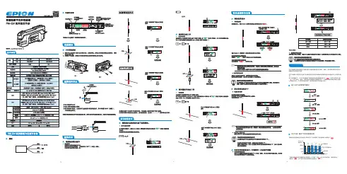
7.基本设定13.9×3=11.732.829.815.1 3.9×3=11.712.152.输入输出段回路图■拆卸压住1方向后,将光纤传感器插入部往2的方向提。
■连接使用时(接插件式)最多可连接16台。
1.分别将放大器单元安装到DIN导轨上。
2.滑动放大器单元,插入接插件直到听到“咔”的声音。
因为会有振动等可能导致连接部脱离时,请使用另售安装配件(PFP-M)进行固定。
请采用相反顺序进行拆卸。
请务必将放大器单元分开后再从DIN导轨上拆下。
1)手动设定能把检测中的入光量调整到「光量调整目标值(2000:出厂时的设定)」左右。
光量调整时必须固定检测物体和光纤头,并且在入光量安定的状态下进行。
辅数字显示中以一条条棒表示模拟条。
(模拟条显示后放开按键。
)■设定方法事先请确认「MODE键设定」的功能设定在「PTUN」(光量调整)的位置上。
选择入光时ON或者遮光时ON。
1.设定动作模式●光量调整错误辅数码显示闪烁2次,光量调整解除能变更「光量调整目标值」。
参照「8.详细设定」。
「检测功能设定为」「SHS」时,「光量调整目标值」无效,设定为最小光量。
切换检测功能会引起入光量变化,此时请在切换检测功能后再次进行光量调整。
2)示教设定 ①2点示教 检测工件有/无2点,将其中间点的光量设置为门槛值。
RUN模式、SET模式均可设定。
用RUN模式设定时,请事先确认「MODE键设定」的功能设定在「2PNT」上。
3.设定门槛值②对射型无工件示教在无工件状态下进行。
可针对无工件入光量,用示教设定中的百分比(0~99%)来③反射型无工件示教在无工件(背景)状态下进行。
可针对无工件入光量,用示教设定中的百分比④最大灵敏度设定 用最大灵敏度设定门槛值。
「检测功能设定为」「DIFF」(微分动作)时,不能使用此方法设定门槛值。
⑤定位示教E3X-DA21-S E3X-DA7-S E3X-DA9-SE3X-DA51-S221ー导线引出式接插件式*1*1:E3X-CN21(母接插件4芯)、E3X-CN22(子接插件2芯)均可使用。

DIGITAL FIBER SENSORFS-V30/31(P)/31C(P)/31M/32(P)/32C(P)Instruction ManualI FS-V31/32/31MI FS-V31P/32P*1 FS-V31/31M only *2 FS-31M only *3 FS-V31P onlyI FS-V31C/32COutput Circuit DiagramInput Circuit DiagramI FS-V31CP/32CPOutput Circuit DiagramInput Circuit DiagramI Socket Cable (Sold Separately)For FS-V31C(P)/32C(P)Pin and wire color table2To dismount the sensor, raise the main body in the direction of the arrow 3 while pushing the both ends of the connected amplifiers in the same way as in step (2).5Sandwich the amplifiers between the end units. Tighten the screws at the top (twoscrews x two units) with a Phillips screwdriver to fix the end units.Move down the fiber lock lever in the direction shown by arrow 4.NoteIf a thin fiber unit is used, an adapter provided with the thin fiber unit will be required.Unless the right adapter is connected, the thin fiber unit will not detect targets correctly. (The adapter is supplied with the fiber unit.)•To connect the coaxial reflective type fiber unit to the amplifier, connect the single-core fiber to the transmitter side, and connect the multiple-core fiber to the receiver side.Pin assignmentPin assignmentOP-73864 (cable length:2 m)OP-73865 (cable length:10 m)with and without a workpiece.12after the calibration is complete. The set value is stored in memory even in that case.I Maximum Sensitivity SettingSet the sensitivity without a workpiece in the case of the reflective type, and with a workpiece in the case of the through-beam or retro-reflective type.Press the SET button for three seconds in the state as shown in the above figure.(Release the button when SET flashes.)When setting the sensitivity, set the value slightly higher than the received light intensity.I Full Auto CalibrationIn this mode, the PV will be set to the mean value of the maximum and minimum incident val-ues obtained within a certain period. Use this mode to detect moving workpieces.1Press the set button for a minimum of three seconds while the target workpiece is passing the sensing area of the fiber unit.•While the SET button is pressed, the sensitivity of the sensor will be set•After the setting is completed, the setting value is displayed on the digital monitor.I Positioning CalibrationFor example, if the target value is set to –10P , the setting value is determined 10% lower than the received light intensity when the SET button is pressed.1When selecting the sensitivity setting method (page 4, No. 2), select the % calibration, and set the target value of calibration.2Taking the desired light intensity as a reference (normally without a workpiece), press the SET button.*While the % calibration is in use, other calibrations (sensitivity setting) cannot be used.*With FS-V31C(P)/32C(P), by periodically performing external calibration from PLC or other devices, stable detection can be performed even with a small sensitivity difference.This function is effective when the light intensity difference is small when judging whether or not there is a workpiece.At Detection mode selection (page 4, No.4), select “Dynamic sensitivity correction mode” beforehand.*How to set the sensitivity is the same as in the normal mode.The DSC indicator illuminates when the DSC function is set.*When Light ON is selected, the upper limit of the correctable range is twice as much as the initial setting value.*The value is stored in memory even after the power is turned off.*The DSC indicator flashes when the light intensity during output OFF greatly fluctuates or the L/D ON selection is inappropriate. In such a case, check the setting again.•When using FS-V31C(P)/32C(P), external inputs can be used.•No inputs are accepted while setting each mode.When external calibration is selected, the operation is the same as with the SET button.I Special FunctionBy performing the following operation, both sensitivity setting and scaling can be performed using external input. Select external calibration (page 4, No. 4-C) and display scaling. The following is the example when using the % calibration.set by pressing the button for 2 seconds or longer.The same steps can be taken to deactivate key lock.For more information on the key lock levels and the PIN number key lock function, refer to page 6.Select “rSt “with the3Select “init” with theDefault settingPower mode:FINEDetection mode: NormalSetting value:50Output selection:L ONI Saving the settings1While pressing, press for 5 seconds or longer.2Select “SAvE” with the3Select “YES” with theI Loading the setting1While pressing , press for 5 seconds or longer.2Select “rSt” with the3Select “[vSt” with thebutton for 3 seconds or longer.Reference。
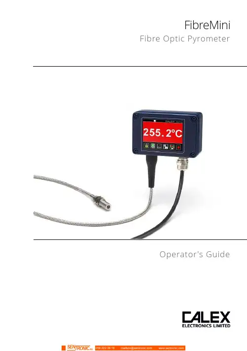
FibreMini Fibre Optic PyrometerOperator's GuideFibreMiniThe FibreMini is an infrared temperature sensor (pyrometer) with a fibre optic sensing head and separate electronics module.The fibre optic sensing head withstands ambient temperatures of up to 200°C and contains no electronics, so it may be used in areas of strong electromagnetic interference. Continuous laser sighting illuminates the position and size of the measurement spot while readings are being taken, without affecting the accuracy of the measurement.A touch screen interface is built into the electronics module, with temperature display, sensor configuration, data logging to optional MicroSD Card, and configurable alarm relay outputs. The sensor works by detecting the infrared radiation emitted from a surface as a result of its own temperature. The amount of radiation emitted is related to the temperature, and the sensor uses this relationship to provide an accurate temperature output.FibreMini sensors are ideal for measuring the surface temperature of many reflective metals in high-temperature applications, including iron and steel, as well as non-reflective non-metals.SpecificationsMeasurement SpecificationsData Logging SpecificationsTouch Screen Interface SpecificationsMechanical SpecificationsEnvironmental SpecificationsThis product is CE marked and RoHS compliant.Electromagnetic Compatibility StandardsConforms to EMC Directive EN61326-1:2006 (Electrical equipment for measurement, control and laboratory use – Industrial) as well as industrial standards for electromagnetic immunity and emissions.Model NumbersFM2.2 - 301 - MT - CRT - 3MFibre OpticCable Length3M = 3 metres5M = 5 metres10M = 10 metresOutput and InterfaceCRT = 4-20 mA output, two alarmrelay outputs, with touch screenBRT = RS485 Modbus output, twoalarm relay outputs, with touchscreenTemperature RangeMT = 250°C to 1000°CHT = 450°C to 2000°CField of View301 = 30:1 divergent optics751 = 75:1 divergent opticsSeriesFM2.2 = FibreMini pyrometer with 2.2 µm spectral responseField of View DiagramsDiagrams show the diameter of the measured spot at each distance, for 90% energy. The sensor will also measure at longer distances than the diagrams show. Measurement accuracy is not affected by distance, however the measured spot size will be larger at longer distances.Emissivity AdjustmentThe default emissivity setting is 0.95. This may be adjusted via the touch screen interface: Settings → Emissivity & CompensationEnter the emissivity of the target surface here. For more information on how to find the target emissivity, contact Calex.Reflected Energy CompensationSettings → Emissivity & CompensationSome of the infrared energy detected by an infrared temperature sensor is not emitted by the target, but is a reflection of its surroundings.To ensure an accurate reading, the sensor needs to know the temperature of the source of that reflected energy. In most applications, the surfaces that surround the target have the same temperature as the sensor itself (e.g. the sensor and target are in the same room). The sensor automatically compensates for the reflected energy, so this setting is not required and should be switched off.However, in some applications, the source of the reflected energy (the surroundings of the target) is much hotter or colder than the sensor itself. In these cases, Reflected Energy Compensation should be enabled and set to the temperature of the surroundings of the target.For example: if the target is inside a furnace and the sensor is outside, the reflected energy is coming from the inner walls of the furnace. Enter the furnace temperature into “Reflected Temperature” and select “Enable Reflected Energy Compensation”.For assistance, contact Calex.Alarm OutputsThe sensor has two alarm relay outputs, rated 24 V DC, 1 A. They are individually configurable via the touch screen interface.Each alarm can be configured as Low or High, with set point and hysteresis.For more information, see “Alarms”.Touch Screen InterfaceThe backlit touch screen interface provides a large, bright display of the measured temperature, two alarm relay outputs, and options for full configuration of the sensor.Using the Touch Screen InterfaceDisplays a large indication of the measured temperature. Thebackground turns bright red when an alarm is activated.MicroSD Card StatusThis icon is displayed when a MicroSD card is inserted, andflashes when data logging is in progress.Scheduled LoggingThis icon is displayed when scheduled data logging isenabled and has yet to begin.Temperature Units °C and °FPress “°C” to switch to °F and vice versa. The units arechanged throughout the interface.Display OptionsPress the measured temperature to select which reading isshown:Average Temperature: The measured temperaturewith averaging, but without hold processing.Hold Temperature: The measured temperature,with averaging and hold processing.Unfiltered Temperature: The unprocessedmeasured temperature.Sighting On/OffSwitches the laser sighting light on or off. The light does notaffect the measurement accuracy.Start/Stop LoggingManually begins or ends data logging (requires MicroSDCard, available separately).If Scheduled Start is enabled in Settings > Data Logging,then logging cannot be started manually.To manually start logging, you must first disable ScheduledStart.Acknowledge AlarmsSwitches the relay outputs for triggered alarms to theirnormal, untriggered state. The background of theTemperature View and Graph screen will stay red, and thealarms will not be triggered again until they are reset (seeLock/UnlockPrevents settings being changed via a four-digit numerical code.To unlock the sensor, enter the password and press the Unlock icon. The default password is 1234.Change PasswordEnter, confirm and save a new four-digit code.GraphDisplays the recent history of the Filtered Temperature and the Sensor Temperature. To scroll backwards and forwards in time, touch the graph and drag it. The graph stores the most recent 24 hours of temperature data.Reset GraphClears and restarts the graph.Return to Scrolling ViewReturns the graph to the real-time scrolling view, showingthe most recent measurements.SettingsAccess the configuration parameters. Press Apply to save the settings, or Exit to leave the screen without saving.SettingsData LoggingConfigure the storage of temperature data and alarm events. A MicroSD Card (optional) must be inserted to use these features.Emissivity & Compensation Settings4 to 20 mA Output (-CRT models) Modbus Address (-BRT models)Output ProcessingAveraging PeriodSelect the required averaging period to smooth the output and slow down the sensor’s response time.Note: averaging prevents the sensor from following rapid temperature changes.Hold ModeWith Peak or Valley Hold, the sensor will continue to display or outputa peak or valley in the measured temperature for a certain time.This feature is ideal for monitoring the temperature of individualobjects on a conveyor, and for ignoring unwanted low readings,such as when a rotating stirring arm in a container of liquidpasses the sensor.PeakThe output returns to the measured temperature after theHold Period.ValleyValley Hold operates in the same way as Peak Hold, exceptthe sensor holds the lowest temperature measuredduring the Hold Period.OffDisables hold processing.Hold PeriodThe peak hold period.AlarmsThe settings for the Alarm 1 and Alarm 2 relay outputs are configured individually.Manually Reset AlarmsAlarm 1 and Alarm 2Manualon the Temperature View oron the Alarms screen.AlarmsAlarm Operation with Hysteresis and Automatic ResetData LoggingData Logging SettingsAlarm Logging SettingsAlarm events can be logged to the MicroSD Card. Alarm log files andsettings are independent from Data Logging.Data LoggingThe sensor can be used as a standalone data logger.Data is stored on a MicroSD card in .csv format and can be viewed and edited easily using spreadsheet software. The MicroSD card is available as an optional accessory, with an SD Card adapter to transfer data to a PC.With a 2 GB card, the user can store 28.4 million readings, which is almost 1 year’s worth of data at 1 sample per second. Larger cards provide more storage.The MicroSD card slot and battery holder are located on the touch screen circuit board in the lid of the electronics module. Readings are time and date stamped using the unit’s internalclock. The clock is reset when the power is disconnected, or it will continue if the optional battery is fitted.Using the Sensor as a Data Logger1. Insert a MicroSD card into the holder on the circuit board inside the lid of the electronics module.2. To retain the date and time when the unit is switched off, fit a battery to the holder on the circuit board inside the lid.3. Replace the lid and connect the sensor power supply.4. To set the number of samples to be logged, the time period between samples, and, if required, to schedule data logging to automatically start, press to access the Settings menu, then press to access the Data Logging options.5. To save data logging settings, press6. To manually start data logging, press on the Temperature View.7. While logging is in progress, the logging icon flashes on the Temperature View.8. To stop data logging, press9. To transfer data to a computer, remove the MicroSD Card from the unit, insert the card into the SD Card adapter (supplied with the MicroSD Card, accessory model MSD) and insert the adapter into an SD Card reader.Installation of MicroSD Card and BatteryThe MicroSD Card and battery slots are located on the touch screen circuit board. Unscrew the lid of the electronics module to access them.The battery is optional. With a battery fitted, the internal clock will continue to run when the power is off. Without a battery, the unit will request the date and time each time the power is cycled.All other settings are stored in permanent memory and will be preserved when it is switched off, regardless of whether a battery is fitted.Data Log FilesData is saved to the MicroSD Card in .csv format. This file format can be opened or imported by spreadsheet software such as Microsoft Excel.A new folder is created on the MicroSD Card for each day that data is logged.A new log file is created every time logging is started. The start time is used as the file name. AccessoriesA range of accessories to suit different applications and industrial environments is available. These may be ordered at any time and added on-site. The following accessories are available from Calex:Fixed mounting bracketAdjustable mounting bracketAir purge collar: The air purge collar is used to keep dust, fumes, moisture, and other contaminants away from the lens. It must be screwed fully onto the sensing head. Air flow should be 5 to 15 l/min. Clean or ‘instrument’ air is recommended.MicroSD Card: Stores logged data. Includes SD Card adapter.OptionsAn optional Calibration Certificate is available if ordered at the same time as the sensor. This UKAS traceable certificate shows the measured temperature at three points across the sensor's temperature range. Contact Calex for details.InstallationThe installation process consists of the following stages:- Preparation- Mechanical installation- Electrical installationPlease read the following sections thoroughly before proceeding with the installation. PreparationDistance and Spot SizeThe size of the area (spot size) to be measured determines the distance between the sensor and the target. The spot size must not be larger than the target. Choose a suitable mounting distance so that the measured spot size is smaller than the target.ReflectionsThe sensor must be installed in a location where energy from lamps, heaters and sunlight cannot be reflected from the target into the lens. This is especially important for low- temperature targets. Using shields may help in this respect. For further information and assistance, contact Calex.Ambient TemperatureThe sensing head may be used between 0°C and 200°C ambient temperature.The electronics module may be used between 0°C and 60°C ambient temperature. Ensure the temperature of the electronics module remains stable, and allow 20 minutes for the unit to adjust to large changes in ambient temperature.Atmospheric QualitySmoke, fumes, dust or steam can contaminate the lens and cause errors in temperature measurement.In these types of environment, the amount of contaminant should be minimised, and the air purge collar should be used to help keep the lens clean.Electrical InterferenceThe sensor is tested to industrial standards for electromagnetic compatibility (EMC). To minimise electromagnetic interference or ‘noise’, the electronics module should be mounted away from motors, generators and such like.The fibre optic sensing head of this pyrometer contains no electronics and may be mounted where electromagnetic interference prevents the other types of sensor from working properly.Power SupplyThe required supply voltage is 24 V DC. Ensure the power supply is of the correct voltage and is capable of providing an output current of at least 100 mA.Mechanical InstallationAffix the sensing head to its mounting. The sensor can be mounted on brackets of your own design, or you can use the mounting bracket accessory.- Switch on the laser sighting to illuminate the measured spot, and adjust the angle of the sensor to aim it.- Ensure the target is larger than the illuminated spot. If not, adjust themeasurement distance for a smaller spot size.Note: The sensor housing must be connected to earth at one point, either the sensing head, the electronics module, or the output cable shield termination. To avoid ground loops, please ensure the sensor is grounded at only one of these points.Electrical InstallationCheck the distance between the sensing head and the electronics module, and between the electronics module and the instrumentation. If necessary, the sensor can be ordered with a longer fibre optic cable between the sensing head and the electronics module.The cable from the electronics module should have an outer diameter between 3.0 and 6.5 mm, with conductors of size 28 to 18 AWG.The terminal blocks may be removed from the electronics module for easy wiring. IMPORTANT: Ensure wiring is correct before switching the power on. Always switch off the power before connecting or disconnecting the sensor.Do not disconnect the touch screen circuit board from the main circuit board while the power is on.Wiring (-BRT models)When connecting several sensors in a single Modbus network, all of the sensors should be connected via a junction box to a single network bus cable, running from the furthest sensor to the Modbus Master.Up to 247 sensors may be connected to a single Modbus network. Each sensor must have a unique Modbus address. Sensors are normally shipped with Modbus address 1. This may be changed using the touch screen interface or via Modbus.To help prevent data reflections, please ensure the cable between each sensor and the main network bus is as short as possible. The network bus should be terminated with a resistor of 120Ω between the RS+ and RS- wires. The PWR- wire of the bus should be connected to the signal ground of the Modbus Master.OperationOnce the sensor is in position and the appropriate power, air and cable connections are secure, the system is ready for continuous operation by completing the following simple steps:1.Turn on the sensor power supply2.Turn on the connected instrumentation3.Read, monitor or log the temperatureImportantBe aware of the following when using the sensor:•If the sensor is exposed to significant changes in ambient temperature (hot to cold, or cold to hot), allow 20 minutes for the temperature to stabilise before taking orrecording measurements.•The electronics module should be positioned away from sources ofelectromagnetic interference. However, the sensing head may be positioned inareas of high electromagnetic interference.•Wires must be connected only to the appropriate terminals.•Do not attempt to open the black cover on the sensor inside the electronics module. Doing so will void the warranty.Viewing through a windowThe sensor is capable of measuring the temperature of a target through a window made of a suitable material transmissive to infrared radiation at 2.0 to 2.6 microns. The emissivity setting of the sensor should be adjusted to compensate for the presence of the window. Please contact Calex for more information on using the sensor with a window.MaintenanceOur customer service representatives are available for application assistance, calibration, repair, and solutions to specific problems. Contact our Service Department before returning any equipment.In many cases, problems can be solved over the telephone. If the sensor is not performing as it should, try to match the symptom below to the problem. If the table does not help, call Calex for further advice.TroubleshootingLens cleaningThe lens must be kept clean and dry for maximum accuracy. Check the condition of the lens regularly.If the lens has become dirty, the measurement accuracy will be affected. Blow off loose particles (if not using the air purge accessory) with an air “puffer”.PasswordThe default password is 1234. The password may be changed via the interface. GuaranteeCalex guarantees each instrument it manufactures to be free from defect in material and workmanship under normal use and service for the period of two years from the date of purchase. This guarantee extends only to the original buyer according to Calex Terms and Conditions of Sale.Issue C – June 2019。
光纤红外测温仪使用说明书陕西瑞光自动化仪表有限公司光纤红外测温仪使用说明书一、概述一切温度高于绝对零度的物体时时刻刻都在不停的辐射红外能量,物体辐射的红外能量的多少与物体的表面温度存在一定的函数关系。
通过探测器接收物体辐射能量再经过计算获得物体表面温度的方法称为红外测温。
红外测温具有响应速度快、灵敏度高、准确度高和测温范围广的优点,尤其是其非接触测量的特点,使红外测温在测量运动物体和难以接近的物体的温度方面得到了很好的应用。
光纤红外测温仪是一种结合红外测温技术和光纤传感技术、实现高精度、高重复性、快速响应、非接触测量的新型测温仪器。
它一般由红外探头、传光光纤、电子模块、信号传输电缆等组成。
被测物体的红外辐射经红外探头透镜汇聚到光纤前端,通过光纤传输及红外滤光片过滤后的红外能量,被红外探测器接收并转换成相应的电信号,重复精度:±0.5%响应时间:≤100ms光谱响应:0.8-1.1u m距离系数:50:1输出方式:4—20mA环境温度:光学探头:-25℃--+150℃电子模块:0℃--+55℃环境湿度:<90%RH4.1测温范围宽,可从300℃--3000℃;4.2采用进口高品质探测器,性能稳定可靠,有较强的环境适应能力;4.3通过光纤传输红外能量,使红外探头与电子处理模块隔离,使信号处理单元受环境影响降至最小,有效的提高了产品抗电磁干扰能力,可在恶劣的环境下使用;4.4具有多种红外探头和探测器适用于不同的应用现场,为用户提供多种组合方式;4.5多种线性输出,可与各类控制仪表、记录仪、计算机测控系统连接;4.6非接触测温极大的提高了仪器使用寿命,一般为高温热电偶的上百倍,响应速度快,可达毫秒量级。
五.使用方法5.1 红外探头的安装红外探头尺寸⑴根据测量要求和该仪器的距离系数,选择合适的安装距离和方位,将红外探头与调整支架良好固定;⑵调整探头测量方向,使被测物体对正观测视场;⑶锁紧调整支架。
光纤传感器的电流测量技术嘿,咱们今天来聊聊光纤传感器的电流测量技术。
先来讲讲我之前遇到的一件事儿吧。
有一次,我在一个工厂里参观,看到工人们正在为测量电流的事儿头疼。
传统的测量方法不仅麻烦,而且误差还不小,这可把他们给愁坏了。
就在这时,有人提到了光纤传感器的电流测量技术,大家的眼睛一下子就亮了起来。
那到底啥是光纤传感器的电流测量技术呢?简单来说,就是利用光纤的特性来精确测量电流。
光纤这玩意儿,大家都知道,细得像头发丝,但是本事可大着呢!它能把光传得又快又准,而且还不容易受到外界的干扰。
在电流测量中,光纤传感器就像是一个超级敏锐的“小侦探”。
它通过感知电流产生的磁场变化,然后把这些变化转化为光信号的变化,最后咱们就能得出精确的电流数值啦。
比如说,在电力系统中,要确保电流的稳定和安全可是至关重要的。
光纤传感器就能实时监测电流的大小和变化,一旦有啥异常,马上就能发出警报,就像是给电力系统装上了一双敏锐的“眼睛”。
再比如,在一些高科技的设备制造中,对电流的测量精度要求那是相当高。
这时候,光纤传感器就能大显身手啦,它能提供非常精确的测量结果,让这些高科技设备能够稳定、高效地运行。
而且啊,光纤传感器的电流测量技术还有很多优点。
它体积小,安装方便,不像那些大块头的测量设备,占地方又不好摆弄。
它的响应速度还特别快,几乎是瞬间就能给出测量结果,一点儿都不拖沓。
另外,它的可靠性也很高。
不像有些测量设备,用着用着就出毛病,光纤传感器能在各种恶劣的环境下工作,高温、低温、潮湿,它都不怕,照样能把电流测量得稳稳当当。
不过,任何技术都不是完美的。
光纤传感器的电流测量技术也有一些挑战和需要改进的地方。
比如说,它的成本相对来说还有点高,这可能会让一些企业在选择的时候有点犹豫。
还有,对于一些特别复杂的电流情况,它的测量精度可能还需要进一步提高。
但总的来说,光纤传感器的电流测量技术就像是一颗正在崛起的新星,有着广阔的发展前景。
相信在未来,随着技术的不断进步,它会变得更加成熟、更加完善,为我们的生活和工作带来更多的便利和安全。
热电堆温度传感器(型号:MRT-311S)使用说明书版本号:1.0实施日期:2020-07郑州炜盛电子科技有限公司ZhengzhouWinsenElectronicTechnologyCo.,Ltd声明本说明书版权属郑州炜盛电子科技有限公司(以下称本公司)所有,未经书面许可,本说明书任何部分不得复制、翻译、存储于数据库或检索系统内,也不可以电子、翻拍、录音等任何手段进行传播。
感谢您使用炜盛科技的系列产品。
为使您更好地使用本公司产品,减少因使用不当造成的产品故障,使用前请务必仔细阅读本说明书并按照所建议的使用方法进行使用。
如果用户不依照本说明书使用或擅自去除、拆解、更换传感器内部组件,本公司不承担由此造成的任何损失。
您所购买产品的颜色、款式及尺寸以实物为准。
本公司秉承科技进步的理念,不断致力于产品改进和技术创新。
因此,本公司保留任何产品改进而不预先通知的权力。
使用本说明书时,请确认其属于有效版本。
同时,本公司鼓励使用者根据其使用情况,探讨本产品更优化的使用方法。
请妥善保管本说明书,以便在您日后需要时能及时查阅并获得帮助。
郑州炜盛电子科技有限公司MRT-311S热电堆温度传感器产品描述MRT-311S型传感器为热电堆温度传感器,基于MEMS工艺将上百对热电偶串联而成。
利用塞贝克原理,当目标与环境之间存在温度差时,传感器输出对应的电压,从而检测出目标存在或目标的温度。
图1:传感器实物图传感器特点TO-46封装;NTC免标定;高灵敏度;响应快;稳定性好;滤光片透过率高。
主要应用◆非接触式温度测量;◆耳温、额温等红外体温非接触测量;◆生产过程的连续温度控制;◆家用电器(微波炉、护发吹风机、空调等)温度测量与控制;◆人体存在式检测;技术指标表1:技术指标性能数值单位备注芯片尺寸 1.1×1.1mm/视场角95Degress大于50%热电堆电阻90±30KΩ25℃噪声电压38nV/Hz1/225℃噪声等效功率0.23nW/Hz1/2500K,1Hz,25℃响应率160±40V/W500K,1Hz,25℃电阻温度系数0.06%/℃25℃~75℃时间常数≤13ms/探测率 1.5×10⁸cmHz1/2/W500K,1Hz,25℃NTC电阻100±0.5%KΩ25℃NTC(β)3950±0.5%/25℃/50℃工作温度-30~125℃/传感器封装尺寸(单位:mm)图2:传感器封装尺寸管脚1234定义热电堆正极NTC热电堆负极GND传感器特性:1.典型热电堆性能(V-T)曲线:测试条件:25℃,TO-46封装,LWP5.5滤光片;图3:典型热电堆性能(V-T)曲线2.滤光片性能曲线:波长范围,5.5~14μm;5.5~14μm,平均透过率≥75%;5μm以下,透过率<1%;图4:滤光片透过率3.热敏电阻(NTC)R-T表;表2:热敏电阻R-T表T(℃)R(KΩ)T(℃)R(KΩ)T(℃)R(KΩ)T(℃)R(KΩ)T(℃)R(KΩ) -402971.00-6427.632887.916222.81967.09 -392790.38-5406.412984.246321.9897 6.87 -382621.46-4386.353080.756421.1998 6.65 -372463.49-3367.403177.416520.4399 6.45 -362315.75-2349.483274.226619.70100 6.25 -352177.56-1332.543371.186719.00101 6.06 -342048.300316.513468.286818.33102 5.87 -331927.371301.333565.516917.68103 5.69 -321814.222286.973662.867017.06104 5.52 -311708.313273.373760.337116.46105 5.35 -301609.164260.483857.917215.89106 5.19 -291516.335248.273955.607315.34107 5.04 -281429.386236.694053.397414.81108 4.89 -271347.917225.724151.277514.30109 4.74 -261271.578215.304249.257613.81110 4.60 -251200.009205.424347.327713.33111 4.47 -241132.8810196.044445.477812.88112 4.34 -231069.9111187.144543.707912.45113 4.21 -221010.8312178.694642.008012.03114 4.09 -21955.3613170.654740.388111.62115 3.97 -20903.2714163.024838.838211.23116 3.86 -19854.3415155.764937.348310.86117 3.75 -18808.3516148.875035.888410.50118 3.64 -17765.1217142.305134.558510.15119 3.54 -16724.4518136.065233.25869.82120 3.44 -15686.2019130.125331.99879.50121 3.34 -14650.1920124.475430.79889.19122 3.25 -13616.2921119.095529.64898.89123 3.16 -12584.3522113.965628.54908.61124 3.07 -11554.2623109.085727.48918.33125 2.99 -10525.9024104.435826.47928.06-9499.1525100.005925.49937.81-8473.922695.786024.56947.56-7450.112791.756123.67957.32推荐电路:使用方法:1.读取热电堆温度传感器2、4管脚电阻值Ra;2.根据Ra在规格书中的R-T表查找到对应环境温度Ta;3.读取传感器1、3脚的电压Va;4.在V-T表里的Ta列中找到与Va值相等或相近的电压值,其对应的行则为被测物体温度T obj。