基于单片机的超声测距仪设计外文翻译
- 格式:doc
- 大小:457.00 KB
- 文档页数:15
基于stm32单片机的超声波测距仪设计报告1. 引言超声波测距仪(Ultrasonic Distance Sensor)是一种常用的测距设备,通过发送超声波脉冲并接收其反射信号来测量目标与测距仪之间的距离。
本报告将详细介绍基于stm32单片机的超声波测距仪的设计过程。
2. 设计原理超声波测距仪的基本原理是利用超声波在空气中的传播速度和反射特性来计算目标物体与测距仪之间的距离。
其中,stm32单片机作为测距仪的控制核心,通过发射超声波脉冲并测量接收到的回波时间来计算距离。
2.1 超声波传播速度超声波在空气中的传播速度约为340m/s,可以通过测量超声波往返的时间来计算出距离。
2.2 超声波反射信号当超声波遇到障碍物时,会产生反射信号,测距仪接收到这些反射信号并测量其时间差,再通过计算即可得到距离。
3. 硬件设计本设计使用stm32单片机作为核心控制器,并搭配超声波发射器和接收器模块。
3.1 超声波发射器超声波发射器负责产生超声波脉冲,并将脉冲信号发送到待测物体。
3.2 超声波接收器超声波接收器负责接收从物体反射回来的超声波信号,并将其转换为电信号。
3.3 stm32单片机stm32单片机作为测距仪的核心控制器,负责发射超声波脉冲、接收反射信号并计算距离。
4. 软件设计本设计涉及的软件设计包括超声波信号发射、接收信号处理和距离计算等。
4.1 超声波信号发射使用stm32单片机的GPIO口控制超声波发射模块,产生一定频率和周期的脉冲信号。
4.2 接收信号处理通过stm32单片机的ADC模块,将超声波接收器接收到的模拟信号转换为数字信号,并对信号进行处理和滤波。
4.3 距离计算根据接收到的超声波反射信号的时间差,结合超声波的传播速度,使用合适的算法计算出距离。
5. 实验结果与分析经过实际测试,基于stm32单片机的超声波测距仪达到了预期的效果。
能够精确测量目标与测距仪之间的距离,并显示在相关的显示设备上。
基于单片机的超声测距系统设计摘要超声波测距法迅速,方便,计算简单,易于做到实时控制,提过基于单片机的超声测距系统的设计能更加深入地了解单片机的实际应用。
本课题完成整个超声波测距系统设计,包括单片机控制电路,发射电路,接收电路,LCD显示电路和温度补偿电路。
本课题硬件部分设计采用最小系统板和所需的超声波收发电路。
程序由计算机仿真并烧入单片机实际调试,最终实物是一个能在5至200cm范围内准确测量距离的便携式系统,经实际测量误差控制在5%以内。
该系统的设计过程加深了对单片机的理解。
本设计的产品也能在实际生活中有很广泛的应用。
关键词:超声波,测距,补偿,模块DESIGN OF ULTRASONIC RANGINGBASED ON SINGLECHIPABSTRACTUltrasonic ranging is so quick and useful,it can be easy to translationed and be controled on time.We can learn much about singlechip during the design of Ultrasonic ranging base on singlechip.The system is made up by singlechip part,send and receive part,LCD part and temperature detective part.With the helping of smallest system and computer,the product which can detective the distance from 5cm to 200cm comes out.The error is only 0.5%. The system can help you take a good learning about singlechip.On the other hand,the system can be used in many environment by its practicality.Key Words: Ultrasonic,Ranging, temperature detective目录摘要 (I)ABSTRACT (II)目录 .................................................................................................................................................. I II 第1章绪论 (1)1.1课题的背景和意义 (1)1.1.1 课题的背景 (1)1.1.2 课题的意义 (1)1.2超声波测距的发展现状趋势 (2)1.3本课题任务 (2)第2章单片机 (3)2.1单片机原理及应用 (3)2.1.1 单片机原理 (3)2.1.2 单片机的应用 (3)2.2单片机发展前景 (4)2.3单片机程序编译环境 (5)2.3.1 KEIL C51 (5)2.3.2 uVision2集成开发环境 (5)2.3.3 编辑器和调试器 (6)2.3.4 C51编译器 (6)2.3.5 部分代码优化 (7)2.3.6 RTX51实时核模块 (8)2.3.7 测试程序 (8)2.3.8 C51 V7版增强功能介绍 (9)第3章超声波测距原理 (10)3.1超声波原理及应用 (10)3.1.1 超声波原理 (10)3.1.2 超声波应用 (10)3.2超声波测距原理 (11)第4章测距系统构成与误差分析 (13)4.1单片机控制器 (13)4.2传感器 (13)4.2.1 超声波传感器原理与选型 (13)4.2.2 温度传感器选型 (14)4.3LCD显示屏 (15)4.4系统误差 (15)4.4.1 系统误差分析 (15)4.4.2 系统误差补偿 (16)第5章系统设计 (17)5.1系统框图 (17)5.2硬件 (17)5.2.1 发射电路 (17)5.2.2 接收电路 (18)5.3程序流程图 (20)5.4系统实物图 (21)5.5测试及数据分析 (21)第6章总结 (25)参考文献 (26)附录1部分程序 (28)致谢 (39)第1章绪论1.1课题的背景和意义1.1.1课题的背景随着科技的迅猛发展越来越多科技成果被广泛的运用到人们的日常生活当中,给我们的生活带来了诸多方便。
基于单片机超声波测距系统的电路设计与实现杨斌;郑翔骥;佘明辉【摘要】This paper adopts software design method and the digital hardware circuit with 8051 single slices of machine as core that shows supersonic range finding to realize function. The system consists of a microprocessor controlled ultrasonic sensor to transmit ultrasonic 8051, When the ultrasonic signal when encountering an obstacle signal return immediately, The ultrasonic sensor receivesa return signal, Send into 8051 only flat machine handlings conversion can reach supersonic sensor the distance that measured and send into LED display show. The circuit uses modular design, In writing for main program put subprogram in advance , project subprogram, take over subprogram, show realization and the modular designs such as subprogram have gone on elaborate comparatively in detail.%文章采用以8051单片机为核心的数字显示超声波测距的硬件电路和软件设计方法来实现功能。

中英文翻译课题:鉴于单片机的超声波测距系统的设计专业电气工程及其自动化学生姓名孙旺班级M电气 112学号28指导教师吴冬春专业系主任顾春雷撰写日期2015年 3月 13日电气工程学院外文原文Ultrasonic ranging system designPublication title: Sensor Review. Bradford: 1993. Vol. 13 ABSTRACT:Ultrasonic ranging technology has wide using worth in many fields ,such as the industrial locale ,vehicle navigation and sonar engineering . Now it has been used in level measurement, self-guided autonomous vehicles, fieldwork robots automotive navigation ,air and underwater target detection ,identification , location and so on.So there is an important practicing meaning to learn the ranging theory and ways deeply. To improve the precision of theultrasonic ranging system in hand , satisfy the request of the engineering personnel for the ranging precision , the bound and the usage, a portable ultrasonic ranging system based on the single chip processor was developed .Keywords: Ultrasound r ,Ranging System ,Single Chip ProcessorWith the development of science and technology, the improvement of people's standard of living, speeding up the development and construction of the city.urban drainage system have greatly developed their situation is constantlyimproving. However, due to historical reasons many unpredictable factors inthe synthesis of her time, the city drainage system. In particular drainagesystem often lags behind urban construction. Therefore, there are often goodbuilding excavation has been building facilities to upgrade the drainage system phenomenon. It brought to the city sewage, and it is clear to the city sewageand drainage culvert in the sewage treatment system. comfort is very importantto people's lives. Mobile robots designed to clear the drainage culvert andthe automatic control system Free sewage culvert clear guarantee robot, therobot is designed to clear the culvert sewage to the core. Control System isthe core component of the development of ultrasonic range finder. Therefore,it is very important to design a good ultrasonic range finder.2. A principle of ultrasonic distance measurementThe principle of piezoelectric ultrasonic generatorPiezoelectric ultrasonic generator is the use of piezoelectric crystalresonators to work. Ultrasonic generator, the internal structure as shown,it has two piezoelectric chip and a resonance plate. When it's two plus pulsesignal, the frequency equal to the intrinsic piezoelectric oscillation frequency chip, the chip will happen piezoelectric resonance, and promote the development of plate vibration resonance, ultrasound is generated. Conversely, if the two are not inter-electrode voltage, when the board received ultrasonic resonance, it will be for vibration suppression of piezoelectric chip, themechanical energy is converted to electrical signals, then it becomes theultrasonic receiver.The traditional way to determine the moment of the echo's arrival is basedon thresholding the received signal with a fixed reference. The threshold ischosen well above the noise level, whereas the moment of arrival of an echois defined as the first moment the echo signal surpasses that threshold. Theintensity of an echo reflecting from an object strongly depends on the object's nature, size and distance from the sensor. Further, the time interval fromthe echo's starting point to the momentwhen it surpasses the threshold changes with the intensity of the echo. As a consequence, a considerable error mayoccur Even two echoes with different intensities arriving exactly at the sametime will surpass the threshold at different moments. The stronger one willsurpass the threshold earlier than the weaker, so it will be considered asbelonging to a nearer object.principle of ultrasonic distance measurementUltrasonic transmitter in a direction to launch ultrasound, in the momentto launch the beginning of time at the same time, the spread of ultrasoundin the air, obstacles on his way to return immediately, the ultrasonic reflected wave received by the receiver immediately stop the clock. Ultrasound in theair as the propagation velocity of 340m / s, according to the timer recordsthe time t, we can calculate the distance between the launch distancebarrier (s), that is: s = 340t / 2Ranging System for the Second Circuit DesignSystem is characterized by single-chip microcomputer to control the use ofultrasonic transmitter and ultrasonic receiver since the launch from time totime, single-chip selection of 8751, economic-to-use, and the chip has 4K ofROM, to facilitate programming. Circuit schematic diagram shown in Figure 2.Figure 1 circuit principle diagram40 kHz ultrasonic pulse generated with the launchRanging system using the ultrasonic sensor of piezoelectric ceramic sensors UCM40, its operating voltage of the pulse signal is 40kHz, which by the single-chip implementation of the following procedures to generate.puzel: mov 14h, # 12h; ultrasonic firing continued 200mshere: cpl ; output 40kHz square wavenop;nop;nop;djnz 14h, here;retRanging in front of single-chip termination circuit input port, singlechip implementation of the above procedure, the port in a 40kHz pulse outputsignal,after amplification transistor T, the drive to launch the first ultrasonic UCM40T, issued 40kHz ultrasonic pulse, and the continued launchof 200ms. Ranging the right and the left side of the circuit, respectively,then input port and , the working principle and circuit in front of the samelocation.Reception and processing of ultrasonicUsed to receive the first launch of the first pair UCM40R, the ultrasonic pulse modulation signal into an alternating voltage, the op-amp amplificationIC1A and after polarization IC1B to IC2. IC2 is locked loop with audio decoderchip LM567, internal voltage-controlled oscillator center frequency of f0 =1/, capacitor C4 determine their target bandwidth. R8-conditioning in the launch of the carrier frequency on the LM567 input signal is greater than 25mV, theoutput from the high jump 8 feet into a low-level, as interrupt request signals to the single-chip processing.Ranging in front of single-chip termination circuit output port INT0 interrupt the highest priority, right or left location of the output circuitwith output gate IC3A access INT1 port single-chip, while single-chip andP1. 4 received input IC3A, interrupted by the process to identify the sourceof inquiry to deal with, interrupt priority level for the first left rightafter. Part of the source code is as follows:receive1: push pswpush accclr ex1; related external interrupt 1jnb , right; pin to 0, ranging from right to interruptservice routine circuitjnb, left; pin to 0, to the left ranging circuit interrupt service routinereturn: SETB EX1; open external interrupt 1pop accpop pswretiright: ...; right location entrance circuit interrupt service routineAjmp Returnleft: ...; left Ranging entrance circuit interrupt service routineAjmp ReturnThe calculation of ultrasonic propagation timeWhen you start firing at the same time start the single-chip circuitrywithin the timer T0, the use of timer counting function records the time andthe launch of ultrasonic reflected wave received time. When you receive the ultrasonic reflected wave, the receiver circuit outputs a negative jump in theend of INT0 or INT1 interrupt request generates a signal, single-chip microcomputer in response to external interrupt request, the implementationof the external interrupt service subroutine, read the time difference, calculating the distance . Some of its source code is as follows: RECEIVE0: PUSH PSWPUSH ACCCLR EX0; related external interrupt 0MOV R7, TH0; read the time valueMOV R6, TL0CLR CMOV A, R6SUBB A, # 0BBH; calculate the time differenceMOV 31H, A; storage resultsMOV A, R7SUBB A, # 3CHMOV 30H, ASETB EX0; open external interrupt 0POP ACCPOP PSWRETIFor a flat target, a distance measurement consists of two phases: acoarse measurement and. a fine measurement:Step 1: Transmission of one pulse train to produce a simple ultrasonic wave.Step 2: Changing the gain of both echo amplifiers according to equation , until the echo is detected.Step 3: Detection of the amplitudes and zero-crossing times of both echoes.Step 4: Setting the gains of both echo amplifiers to normalize the output at,say 3 volts. Setting the period of the next pulses according to the :period of echoes. Setting the time window according to the data of step2.Step 5: Sending two pulse trains to produce an interfered wave. Testing thezero-crossing times and amplitudes of the echoes. If phase inversionoccurs in the echo, determine to otherwise calculate to by interpolationusing the amplitudes near the trough. Derive t sub m1 and t sub m2 .Step 6: Calculation of the distance y using equation .4. The ultrasonic ranging system software designSoftware is divided into two parts, the main program and interrupt service routine. Completion of the work of the main program is initialized, each sequence of ultrasonic transmitting and receiving control.Interrupt service routines from time to time to complete three of the rotationdirection of ultrasonic launch, the main external interrupt service subroutine to read the value of completion time, distance calculation, the results ofthe output and so on.5. ConclusionsRequired measuring range of 30cm ~ 200cm objects inside the plane to doa number of measurements found that the maximum error is , and good reproducibility. Single-chip design can be seen on the ultrasonic ranging system has a hardware structure is simple, reliable, small features such as measurement error. Therefore, it can be used not only for mobile robot can be used in other detection systems.Thoughts: As for why the receiver do not have the transistor amplifiercircuit, because the magnification well, integrated amplifier, but also withautomatic gain control level, magnification to 76dB, the center frequency is 38k to 40k, is exactly resonant ultrasonic sensors frequencyREFERENCES1. Fox, ., Khuri-Yakub, . and Kino, ., "High Frequency Acoustic WaveMeasurement in Air", in Proceedings of IEEE 1983 Ultrasonic Symposium, October 31-2 November, 1983, Atlanta, GA, pp. 581-4.2.Martin Abreu, ., Ceres, R. and Freire, T., "Ultrasonic Ranging: EnvelopeAnalysis Gives Improved Accuracy", Sensor Review, Vol. 12 No. 1, 1992, pp.17-21.3. Parrilla,M., Anaya, . and Fritsch, C., "Digital Signal Processing Techniques for High Accuracy Ultrasonic Range Measurements", IEEE Transactions: Instrumentation and Measurement, Vol. 40 No. 4, August 1991, pp. 759-63.4.Canali, C., Cicco, ., Mortem, B., Prudenziati, M., and Taron, A., "ATemperature Compensated Ultrasonic Sensor Operating in Air for Distanceand Proximity Measurement", IEEE Transaction on Industry Electronics, Vol.IE-29 No. 4, 1982, pp. 336-41.5.Martin, ., Ceres, R., Calderon, L and Freire, T., "Ultrasonic Ranging GetsThermal Correction", Sensor Review, Vol. 9 No. 3, 1989, pp. 153-5.外文译文超声波测距仪系统设计纲要:超声测距技术在工业现场、车辆导航、水声工程等领域都拥有宽泛的应用价值,当前已应用于物位丈量、机器人自动导航以及空气中与水下的目标探测、辨别、定位等场合。
基于单片机的超声波测距仪的设计与实现中文摘要本设计基于单片机AT89C52,利用超声波传感器HC-SR04、LCD显示屏及蜂鸣器等元件共同实现了带温度补偿功能可报警的超声波测距仪。
我们以AT89C52作为主控芯片,通过计算超声波往返时间从而测量与前方障碍物的距离,并在LCD显示。
单片机控制超声波的发射。
然后单片机进行处理运算,把测量距离与设定的报警距离值进行比较判断,当测量距离小于设定值时,AT89C52发出指令控制蜂鸣器报警,并且AT89C52控制各部件刷新各测量值。
在不同温度下,超声波的传播速度是有差别的,所以我们通过DS18B20测温单元进行温度补偿,减小因温度变化引起的测量误差,提高测量精度。
超声波测距仪可以实现4m以内的精确测距,经验证误差小于3mm。
关键词:超声波;测距仪;AT89C52;DS18B20;报警Design and Realization of ultrasonic range finder basedABSTRACTThe design objective is to design and implement microcontroller based ultrasonic range finder. The main use of AT89C52, HC-SR04 ultrasonic sensor alarm system complete ranging production. We AT89C52 as the main chip, by calculating the round-trip time ultrasound to measure the distance to obstacles in front of, and displayed in the LCD. SCM ultrasonic transmitter. Then the microcontroller for processing operation to measure the distance and set alarm values are compared to judge distance, when measured distance is less than the set value, AT89C52 issue commands to control the buzzer alarm, and control each member refreshAT89C52 measured values. Because at different temperatures, ultrasonic wave propagation velocity is a difference, so we DS18B20 temperature measurement by the temperature compensation unit, reducing errors due to temperature changes, and improve measurement accuracy. Good design can achieve precise range ultrasonic distance within 4m, proven error is less than 3mm.Keywords:Ultrasonic;Location;AT89C52;DS18B20;Alarm目录第一章前言 (1)1.1 课题背景及意义 (1)1.1.1超声波特性 (1)1.1.2超声波测距 (2)1.2 超声波模块基本介绍 (3)1.2.1 超声波的电器特性 (3)1.2.2 超声波的工作原理 (5)1.3主要研究内容和关键问题 (6)第二章方案总体设计 (7)2.1 超声波测距仪功能 (7)2.2设计要求 (8)2.3系统基本方案 (9)2.3.1方案比较 (9)2.3.2方案汇总 (11)第三章系统硬件设计 (13)3.1 单片机最小系统 (13)3.2 超声波测距模块 (13)3.3 显示模块 (15)3.4温度补偿电路 (15)3.5 蜂鸣报警电路 (16)第四章系统软件设计 (17)4.1 A T89C52程序流程图 (17)4.2 计算距离程序流程图 (19)4.3 报警电路程序流程图 (19)4.4 超声波回波接收程序流程图 (20)第五章系统的调试与测试 (21)5.1 安装 (21)5.2 系统的调试 (21)第六章总结 (23)参考文献 (24)致谢.............................................................................................................................. 错误!未定义书签。
超声波测距毕业论文中英文对照资料外文翻译文献超声测距技术在工业现场、车辆导航、水声工程等领域都具有广泛的应用价值,目前已应用于物位测量、机器人自动导航以及空气中与水下的目标探测、识别、定位等场合。
因此,深入研究超声的测距理论和方法具有重要的实践意义。
为了进一步提高测距的精确度,满足工程人员对测量精度、测距量程和测距仪使用的要求,本文研制了一套基于单片机的便携式超声测距系统。
1随着技术的发展,人们生活水平的提高,城市发展建设加快,城市给排水系统也有较大展,其状况不断改善。
但是,由于历史原因合成时间住的许多不可预见因素,城市给排水系统,特别是排水系统往往落后于城市建设。
因此,经常出现开挖已经建设好的建筑设施来改造排水系统的现象。
城市污水给人们带来了困扰,因此箱涵的排污疏通对大城市给排水系统污水处理,人们生活舒适显得非常重要。
而设计研制箱涵排水疏通移动机器人的自动控制系统,保证机器人在箱涵中自由排污疏通,是箱涵排污疏通机器人的设计研制的核心部分。
控制系统核心部分就是超声波测距仪的研制。
因此,设计好的超声波测距仪就显得非常重要了。
2 波测距原理2.1压电式超声波发生器原理压电式超声波发生器实际上是利用压电晶体的谐振来工作的。
超声波发生器内部结构,它有两个压电晶片和一个共振板。
当它的两极外加脉冲信号,其频率等于压电晶片的固有振荡频率时,压电晶片将会发生共振,并带动共振板振动,便产生超声波。
反之,如果两电极间未外加电压,当共振板接收到超声波时,将压迫压电晶片作振动,将机械能转换为电信号,这时它就成为超声波接收器了。
测量脉冲到达时间的传统方法是以拥有固定参数的接收信号开端为基础的。
这个界限恰恰选于噪音水平之上,然而脉冲到达时间被定义为脉冲信号刚好超过界限的第一时刻。
一个物体的脉冲强度很大程度上取决于这个物体的自然属性尺寸还有它与传感器的距离。
进一步说,从脉冲起始点到刚好超过界限之间的时间段随着脉冲的强度而改变。
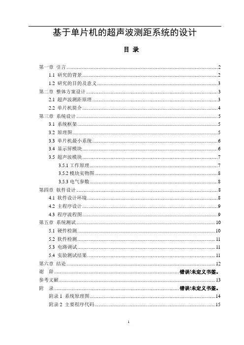
基于单片机的超声波测距系统的设计目录第一章引言 (2)1.1 研究的背景 (2)1.2 研究的目的及意义 (3)第二章整体方案设计 (3)2.1 超声波测距原理 (3)2.2 单片机简介 (4)第三章系统设计 (5)3.1 系统框架 (5)3.2 原理图 (5)3.3 单片机最小系统 (6)3.4 显示屏模块 (6)3.5 超声波模块 (7)3.5.1工作原理 (7)3.5.2模块实物图 (8)3.5.3电气参数 (8)第四章软件设计 (8)4.1 软件设计环境 (8)4.2 主程序设计 (9)4.3 程序流程图 (9)第五章系统测试 (10)5.1 硬件检测 (10)5.2 软件检测 (11)5.3 电路调试 (11)5.4 实验测试结果 (11)第六章结论 (12)谢辞...................................................................................................... 错误!未定义书签。
参考文献. (13)附录...................................................................................................... 错误!未定义书签。
附录1 系统原理图 (14)附录2 主要程序代码 (15)摘要作者设计了一款简单的超声波测距系统。
该设计以AT89C51单片机为核心进行控制;通过按键进行手动控制,方便操作;以超声波为媒介对目标进行测距,由于测距方式为非接触式测量,有利于在特殊环境下进行测距,较为安全快捷;使用Keil C编程软件,进行软件设计,实现了软硬件的结合。
该设计仅实现了测距功能,适用环境不具体,较为简单,实用性欠佳。
由于选用的超声波传感器质量一般,受温湿度变化的影响较大,不宜在环境变化较大的地区使用,功能尚需改进。
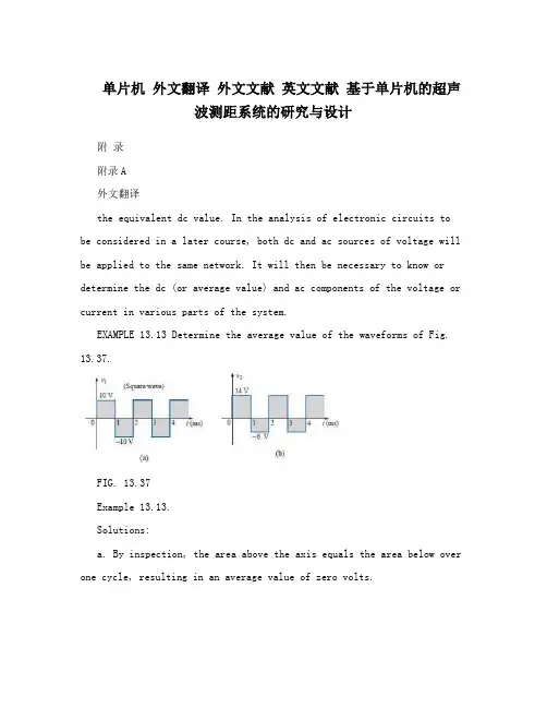
单片机外文翻译外文文献英文文献基于单片机的超声波测距系统的研究与设计附录附录A外文翻译the equivalent dc value. In the analysis of electronic circuits to be considered in a later course, both dc and ac sources of voltage will be applied to the same network. It will then be necessary to know or determine the dc (or average value) and ac components of the voltage or current in various parts of the system.EXAMPLE 13.13 Determine the average value of the waveforms of Fig. 13.37.FIG. 13.37Example 13.13.Solutions:a. By inspection, the area above the axis equals the area below over one cycle, resulting in an average value of zero volts.b. Using Eq.(13.26):as shown in Fig. 13.38.26In reality, the waveform of Fig. 13.37(b) is simply the square wave of Fig. 13.37(a) with a dc shift of 4 V; that is v2 =v1 + 4 VEXAMPLE 13.14 Find the average values of the following waveforms over one full cycle:a. Fig. 13.39.b. Fig. 13.40.27Solutions:We found the areas under the curves in the preceding example by using a simple geometric formula. If we should encounter a sine wave or any other unusual shape, however, we must find the area by some other means. We can obtain a good approximation of the area by attempting to reproduce the original wave shape using a number of small rectangles or other familiar shapes, the area of which we already know through simple geometric formulas. For example,the area of the positive (or negative) pulse of a sine wave is 2Am. Approximating this waveform by two triangles (Fig. 13.43), weobtain(using area1/2 base height for the area of a triangle) a rough idea of the actual area:A closer approximation might be a rectangle with two similar triangles(Fig. 13.44):28which is certainly close to the actual area. If an infinite number of forms were used, an exact answer of 2Am could be obtained. For irregular waveforms, this method can be especially useful if data such as the average value are desired. The procedure of calculus that gives the exact solution 2Am is known as integration. Integration is presented here only to make the method recognizable to the reader; it is not necessary to be proficient in its use to continue with this text. It is a useful mathematical tool, however,and should be learned. Finding the area under the positive pulse of a sine wave using integration, we havewhere ? is the sign of integration, 0 and p are the limits of integration, Am sin a is thefunction to be integrated, and da indicates that we are integrating with respect to a.Integrating, we obtainSince we know the area under the positive (or negative) pulse, we can easily determine the average value of the positive (or negative) region of a sine wave pulse by applying Eq. (13.26):For the waveform of Fig. 13.45,29EXAMPLE 13.15 Determine the average value of the sinusoidal waveform of Fig. 13.46.Solution: By inspection it is fairly obvious thatthe average value of a pure sinusoidal waveform over one full cycle is zero.EXAMPLE 13.16 Determine the average value of the waveform of Fig. 13.47.Solution: The peak-to-peak value of the sinusoidal function is16 mV +2 mV =18 mV. The peak amplitude of the sinusoidal waveform is, therefore, 18 mV/2 =9 mV. Counting down 9 mV from 2 mV(or 9 mV up from -16 mV) results in an average or dc level of -7 mV,as noted by the dashed line of Fig. 13.47.EXAMPLE 13.17 Determine the average value of the waveform of Fig. 13.48.Solution:30EXAMPLE 13.18 For the waveform of Fig. 13.49, determine whether the averagevalue is positive or negative, and determine its approximate value.Solution: From the appearance of the waveform, the average value is positive and in the vicinity of 2 mV. Occasionally, judgments of this type will have to be made. InstrumentationThe dc level or average value of any waveform can be found using a digital multimeter (DMM) or an oscilloscope. For purely dccircuits,simply set the DMM on dc, and readthe voltage or current levels.Oscilloscopes are limited to voltage levels using the sequence of steps listed below:1. First choose GND from the DC-GND-AC option list associated with each vertical channel. The GND option blocks any signal to which the oscilloscope probe may be connected from entering the oscilloscope and responds with just a horizontal line. Set the resulting line in the middle of the vertical axis on the horizontal axis, as shown in Fig. 13.50(a).2. Apply the oscilloscope probe to the voltage to be measured (ifnot already connected), and switch to the DC option. If a dc voltage is present, the horizontal line will shift up or down, as demonstrated in Fig. 13.50(b). Multiplying the shift by the vertical sensitivity will result in the dc voltage. An upward shift is a positive voltage (higher31potential at the red or positive lead of the oscilloscope), while a downward shift is a negative voltage (lower potential at the red or positive lead of the oscilloscope). In general,1. Using the GND option, reset the horizontal line to the middle of the screen.2. Switch to AC (all dc components of the signal to whichthe probe is connected will be blocked from entering the oscilloscope—only the alternating, or changing,components will be displayed).Note the location of some definitive point on the waveform, such as the bottom of the half-wave rectified waveform of Fig. 13.51(a); that is, note its position on the vertical scale. For the future, whenever youuse the AC option, keep in mind that the computer will distribute the waveform above and below the horizontal axis such that the average value is zero; that is, the area above the axis will equal the area below. 3. Then switch to DC (to permit both the dc and the ac components of the waveform to enter the oscilloscope), and note the shift in the chosen level of part 2, as shown in Fig. 13.51(b). Equation(13.29) can then be used to determine the dc or average value of the waveform. For the waveform of Fig. 13.51(b), the average value is aboutThe procedure outlined above can be applied to any alternating waveform such as the one in Fig. 13.49. In some cases the average valuemay require moving the starting position of the waveform under the AC option to a different region of the screen or choosing a higher voltage scale. DMMs can read the average or dc level of any waveform by simply choosing the appropriate scale.3213.7 EFFECTIVE (rms) VALUESThis section will begin to relate dc and ac quantities with respect to the power delivered to a load. It will help us determine the amplitude of a sinusoidal ac current required to deliver the same power as a particular dc current. The question frequently arises, How is it possible for a sinusoidal ac quantity to deliver a net power if, over a full cycle, the net current in any one direction is zero (average value 0)? It would almost appear that the power delivered during the positive portion of the sinusoidal waveform is withdrawn during the negative portion, and since the two are equal in magnitude, the net power delivered is zero. However, understand that irrespective of direction, currentof any magnitude through a resistor will deliver power to that resistor. In other words,during the positive or negative portions of a sinusoidal ac current, power is being delivered at eachinstant of time to the resistor. The power delivered at each instant will, of course, vary with the magnitude of the sinusoidal ac current, but there will be a net flow during either the positive or the negativepulses with a net flow over the full cycle. The net power flow will equal twice that delivered by either the positive or the negative regions of sinusoidal quantity. A fixed relationship between ac and dc voltages and currents can be derived from the experimental setup shown in Fig. 13.52. A resistor in a water bath is connected by switches to a dc and an ac supply. If switch 1 is closed, a dc current I, determined by the resistance R and battery voltage E, will be established through theresistor R. The temperature reached by the water is determined by the dc power dissipated in the form of heat by the resistor.If switch 2 is closed and switch 1 left open, the ac current through the resistor will have a peak value of Im. The temperature reached by the water is now determined by the ac power dissipated in the form of heat by the resistor. The ac input is varied until the temperature is the same as that reached with the dc input. When this is accomplished, the average electrical power delivered to the resistor R by the ac source is the same asthat delivered by the dc source. The power delivered by the ac supply at any instant of time is33The average power delivered by the ac source is just the first term, since the average value of a cosine wave is zero even though the wave may have twice the frequency of the original input current waveform. Equating the average power delivered by the ac generator to that delivered by the dc source,which, in words, states thatthe equivalent dc value of a sinusoidal current or voltage is 1/2 or 0.707 of itsmaximum value.The equivalent dc value is called the effective value of the sinusoidal quantity.In summary,As a simple numerical example, it would require an ac current with a peak value of 2 (10) 14.14 A to deliver the same power to the resistorin Fig. 13.52 as a dc current of 10 A. The effective value of any quantity plotted as a function of time can be found by using the following equation derived from the experiment just described:34which, in words, states that to find the effective value, the function i(t) must first besquared. After i(t) is squared, the area under the curve isfound by integration. It is then divided by T, the length of the cycle or the period of the waveform, to obtain the average or mean value of thesquared waveform. The final step is to take the square root of the meanvalue. This procedure gives us another designation forthe effectivevalue, the root-mean-square (rms) value. In fact, since therms term isthe most commonly used in the educational and industrial communities,it will used throughout this text. EXAMPLE 13.19 Find therms values of the sinusoidal waveform in each part of Fig. 13.53.Solution: For part (a), Irms 0.707(12 10 3 A) 8.484 mA.For part (b), againIrms 8.484 mA. Note that frequency did notchange the effective valuein (b) above compared to (a). For part (c),Vrms 0.707(169.73 V) 120 V, the same as available from a home outlet.EXAMPLE 13.20 The 120-V dc source of Fig. 13.54(a) delivers 3.6 W to the load. Determine the peak value of the applied voltage (Em) and the current (Im) if the acsource [Fig. 13.54(b)] is to deliver the same power to the load.35Solution:EXAMPLE 13.21 Find the effective or rms value of the waveform of Fig.13.55.Solution:36EXAMPLE 13.22 Calculate the rms value of the voltage of Fig. 13.57.Solution:EXAMPLE 13.23 Determine the average and rms values of the square wave of Fig. 13.59.37Solution: By inspection, the average value is zero.The waveforms appearing in these examples are the same as thoseused in the examples on the average value. It might prove interesting tocompare the rms and average values of these waveforms.The rms values of sinusoidal quantities such as voltage or currentwill be represented by E and I. These symbols are the same as thoseused for dc voltages and currents. To avoid confusion, the peak valueof a waveform will always have a subscript m associated with it: Imsin qt. Caution: When finding the rms value ofthe positive pulse of asine wave, note that the squared area is not simply (2Am)24A2m; itmust be found by a completely new integration. This will always bethe case for any waveform that is not rectangular.A uniquesituation arises if a waveform has both a dc and an ac componentthat may be due to a source such as the one in Fig. 13.61. Thecombination appears frequently in the analysis of electronic networkswhere both dc and ac levels are present in the same system.38The question arises, What is the rms value of the voltage vT? Onemight be tempted tosimply assume that it is the sum of the rms valuesof each component of the waveform; that is, VT rms 0.7071(1.5 V) 6 V 1.06 V 6 V 7.06 V. However, the rms value is actuallydetermined bywhich for the above example is39直流值相等。
Ultrasonic distance meterDocument Type and Number:United States Patent 5442592 Abstract:An ultrasonic distance meter cancels out the effects of temperature and humidity variations by including a measuring unit and a reference unit. In each of the units, a repetitive series of pulses is generated, each having a repetition rate directly related to the respective distance between an electroacoustic transmitter and an electroacoustic receiver. The pulse trains are provided to respective counters, and the ratio of the counter outputs is utilized to determine the distance being measured. Publication Date:08/15/1995 Primary Examiner:Lobo, Ian J.1、Backgroud of the inventionThis invention relates to apparatus for the measurement of distance and, more particularly, to such apparatus which transmits ultrasonic waves between two points. Precision machine tools must be calibrated. In the past, this has been accomplished utilizing mechanical devices such as calipers, micrometers, and the like. However, the use of such devices does not readily lend itself to automation techniques. It is known that the distance between two points can be determined by measuring the propagation time of a wave travelling between those two points. One such type of wave is an ultrasonic, or acoustic, wave. When an ultrasonic wave travels between two points, the distance between the two points can be measured by multiplying the transit time of the wave by the wave velocity in the medium separating the two points. It is therefore an object of the present invention to provide apparatus utilizing ultrasonic waves to accurately measure the distance between two points.When the medium between the two points whose spacing is being measured is air, the sound velocity is dependent upon the temperature and humidity of the air. It is therefore a further object of the,present invention to provide apparatus of the type described which is independent of temperature and humidity variations.2、summary of the inventionThe foregoing and additional objects are attained in accordance with the principles of this invention by providing distance measuring apparatus which includes a reference unit and a measuring unit. The reference and measuring units are the same and each includes anelectroacoustic transmitter and an electroacoustic receiver. The spacing between the transmitter and the receiver of the reference unit is a fixed reference distance, whereas the spacing between the transmitter and receiver of the measuring unit is the distance to be measured. In each of the units, the transmitter and receiver are coupled by a feedback loop which causes the transmitter to generate an acoustic pulse which is received by the receiver and converted into an electrical pulse which is then fed back to the transmitter, so that a repetitive series of pulses results. The repetition rate of the pulses is inversely related to the distance between the transmitter and the receiver. In each of the units, the pulses are provided to a counter. Since the reference distance is known, the ratio of the counter outputs is utilized to determine the desired distance to be measured. Since both counts are identically influenced by temperature and humidity variations, by taking the ratio of the counts, the resultant measurement becomes insensitive to such variations.3、brief description of the inventionThe foregoing will be more readily apparent upon reading the following description in conjunction with the drawing in which the single FIGURE schematically depicts apparatus constructed in accordance with the principles of this invention.4、detailed descriptionReferring now to the drawing, there is shown a measuring unit 10 and a reference unit 12, both coupled to a utilization means 14. The measuring unit 10 includes an electroacoustic transmitter 16 and an electroacoustic receiver 18. The transmitter 16 includes piezoelectric material 20 sandwiched between a pair of electrodes 22 and 24. Likewise, the receiver 18 includes piezoelectric material 26 sandwiched between a pair of electrodes 28 and 30. As is known, by applying an electric field across the electrodes 22 and 24, stress is induced in the piezoelectric material 20. If the field varies, such as by the application of an electrical pulse, an acoustic wave 32 is generated. As is further known, when an acoustic wave impinges upon the receiver 18, this induces stress in the piezoelectric material 26 which causes an electrical signal to be generated across the electrodes 28 and 30. Although piezoelectric transducers have been illustrated, other electroacoustic devices may be utilized, such as, for example, electrostatic, electret or electromagnetic types.As shown, the electrodes 28 and 30 of the receiver 18 are coupled to the input of an amplifier 34, whose output is coupled to the input of a detector 36. The detector 36 is arranged to provide a signal to the pulse former 38 when the output from the amplifier 34 exceeds a predetermined level. The pulse former 38 then generates a trigger pulse which is provided to the pulse generator 40. In order to enhance the sensitivity of the system, the transducers 16 and 18 are resonantly excited. There is accordingly provided a continuous wave oscillator 42 which provides a continuous oscillating signal at a fixed frequency, preferably the resonant frequency of the transducers 16 and 18. This oscillating signal is provided to the modulator 44. To effectively excite the transmitter 16, it is preferable to provide several cycles of the resonant frequency signal, rather than a single pulse or single cycle. Accordingly, the pulse generator 40 is arranged, in response to the application thereto of a trigger pulse, to provide a control pulse to the modulator 44 having a time duration equal the time duration of a predetermined number of cycles of the oscillating signal from the oscillator 42. This control pulse causes the modulator 44 to pass a "burst" of cycles to excite the transmitter 16.When electric power is applied to the described circuitry, there is sufficient noise at the input to the amplifier 34 that its output triggers the pulse generator 40 to cause a burst of oscillating cycles to be provided across the electrodes 22 and 24 of the transmitter 16. The transmitter 16 accordingly generates an acoustic wave 32 which impinges upon the receiver 18. The receiver 18 then generates an electrical pulse which is applied to the input of the amplifier 34, which again causes triggering of the pulse generator 40. This cycle repeats itself so that a repetitive series of trigger pulses results at the output of the pulse former 38. This pulse train is applied to the counter 46, as well as to the pulse generator 40.The transmitter 16 and the receiver 18 are spaced apart by the distance "D" which it is desired to measure. The propagation time "t" for an acoustic wave 32 travelling between the transmitter 16 and the receiver 18 is given by: t=D/V swhere V s is the velocity of sound in the air between the transmitter 16 and the receiver 18. The counter 46 measures the repetition rate of the trigger pulses, which is equal to 1/t. Therefore, the repetition rate is equal to V s /D. The velocity of sound in air is a function of the temperature and humidity of the air, as follows: ##EQU1## where T is the temperature, p is the partial pressure of the water vapor, H is the barometric pressure, Γ w and Γ a are theratio of constant pressure specific heat to constant volume specific heat for water vapor and dry air, respectively. Thus, although the repetition rate of the trigger pulses is measured very accurately by the counter 46, the sound velocity is influenced by temperature and humidity so that the measured distance D cannot be determined accurately.In accordance with the principles of this invention, a reference unit 12 is provided. The reference unit 12 is of the same construction as the measuring unit 10 and therefore includes an electroacoustic transmitter 50 which includes piezoelectric material 52 sandwiched between a pair of electrodes 54 and 56, and an electroacoustic receiver 58 which includes piezoelectric material 60 sandwiched between a pair of electrodes 62 and 64. Again, transducers other than the piezoelectric type can be utilized. The transmitter 50 and the receiver 58 are spaced apart a known and fixed reference distance "D R ". The electrodes 62 and 64 are coupled to the input of the amplifier 66, whose output is coupled to the input of the detector 68. The output of the detector 68 is coupled to the pulse former 70 which generates trigger pulses. The trigger pulses are applied to the pulse generator 72 which controls the modulator 74 to pass bursts from the continuous wave oscillator 76 to the transmitter 50. The trigger pulses from the pulse former 70 are also applied to the counter 78.Preferably, all of the transducers 16, 18, 50 and 58 have the same resonant frequency. Therefore, the oscillators 42 and 76 both operate at that frequency and the pulse generators 40 and 72 provide equal width output pulses.In usage, the measuring unit 10 and the reference unit 12 are in close proximity so that the sound velocity in both of the units is the same. Although the repetition rates of the pulses in the measuring unit 10 and the reference unit 12 are each temperature and humidity dependent, it can be shown that the distance D to be measured is related to the reference distance D R as follows: i D=D R (1/t R )/(1/t) where t R is the propagation time over the distance D R in the reference unit 12. This relationship is independent of both temperature and humidity.Thus, the outputs of the counters 46 and 78 are provided as inputs to the microprocessor 90 in the utilization means 14. The microprocessor 90 is appropriately programmed to provide an output which is proportional to the ratio of the outputs of the counters 46 and 78, which in turn are proportional to the repetition rates of the respective trigger pulse trains of the measuring unit 10 and the reference unit 12. As described, this ratiois independent of temperature and humidity and, since the reference distance D R is known, provides an accurate representation of the distance D. The utilization means 14 further includes a display 92 which is coupled to and controlled by the microprocessor 90 so that an operator can readily determine the distance D.Experiments have shown that when the distance between the transmitting and receiving transducers is too small, reflections of the acoustic wave at the transducer surfaces has a not insignificant effect which degrades the measurement accuracy. Accordingly, it is preferred that each transducer pair be separated by at least a certain minimum distance, preferably about four inches.Accordingly, there has been disclosed improved apparatus for the measurement of distance utilizing ultrasonic waves. While an illustrative embodiment of the present invention has been disclosed herein, it is understood that various modifications and adaptations to the disclosed embodiment will be apparent to those of ordinary skill in the art and it is intended that this invention be limited only by the scope of the appended claims.anging system is to understand the front of the robot, left and right environment to provide a movement away from the information. (Similar to GPS Positioning System)A principle of ultrasonic distance measurement1, the principle of piezoelectric ultrasonic generatorPiezoelectric ultrasonic generator is the use of piezoelectric crystal resonators to work. Ultrasonic generator, the internal structure as shown in Figure 1, it has two piezoelectric chip and a resonance plate. When it's two plus pulse signal, the frequency equal to the intrinsic piezoelectric oscillation frequency chip, the chip will happen piezoelectric resonance, and promote the development of plate vibration resonance, ultrasound is generated. Conversely, if the two are not inter-electrode voltage, when the board received ultrasonic resonance, it will be for vibration suppression of piezoelectric chip, the mechanical energy is converted to electrical signals, then it becomes the ultrasonic receiver.5.the principle of ultrasonic distance measurementUltrasonic transmitter in a direction to launch ultrasound, in the moment to launch the beginning of time at the same time, the spread of ultrasound in the air, obstacles on his way to return immediately, the ultrasonic reflected wave received by the receiver immediately stopthe clock. Ultrasound in the air as the propagation velocity of 340m / s, according to the timer records the time t, we can calculate the distance between the launch distance barrier (s), that is: s = 340t / 2Ultrasonic Ranging System for the Second Circuit DesignSystem is characterized by single-chip microcomputer to control the use of ultrasonic transmitter and ultrasonic receiver since the launch from time to time, single-chip selection of 8751, economic-to-use, and the chip has 4K of ROM, to facilitate programming. Circuit schematic diagram shown in Figure 2. Draw only the front range of the circuit wiring diagram, left and right in front of Ranging circuits and the same circuit, it is omitted.1,40 kHz ultrasonic pulse generated with the launchRanging system using the ultrasonic sensor of piezoelectric ceramic sensors UCM40, its operating voltage of the pulse signal is 40kHz, which by the single-chip implementation of the following procedures to generate.puzel: mov 14h, # 12h; ultrasonic firing continued 200mshere: cpl p1.0; output 40kHz square wavenop;nop;nop;djnz 14h, here;retRanging in front of single-chip termination circuit P1.0 input port, single chip implementation of the above procedure, the P1.0 port in a 40kHz pulse output signal, after amplification transistor T, the drive to launch the first ultrasonic UCM40T, issued 40kHz ultrasonic pulse, and the continued launch of 200ms. Ranging the right and the left side of the circuit, respectively, then input port P1.1 and P1.2, the working principle and circuit in front of the same location.6.reception and processing of ultrasonicUsed to receive the first launch of the first pair UCM40R, the ultrasonic pulse modulation signal into an alternating voltage, the op-amp amplification IC1A and after polarization IC1B to IC2. IC2 is locked loop with audio decoder chip LM567, internalvoltage-controlled oscillator center frequency of f0 = 1/1.1R8C3, capacitor C4 determine their target bandwidth. R8-conditioning in the launch of the carrier frequency on the LM567 input signal is greater than 25mV, the output from the high jump 8 feet into a low-level, as interrupt request signals to the single-chip processing.Ranging in front of single-chip termination circuit output port INT0 interrupt the highest priority, right or left location of the output circuit with output gate IC3A access INT1 port single-chip, while single-chip P1.3 and P1. 4 received input IC3A, interrupted by the process to identify the source of inquiry to deal with, interrupt priority level for the first left right after. Part of the source code is as follows:receive1: push pswpush accclr ex1; related external interrupt 1jnb p1.1, right; P1.1 pin to 0, ranging from right to interrupt service routine circuitjnb p1.2, left; P1.2 pin to 0, to the left ranging circuit interrupt service routinereturn: SETB EX1; open external interrupt 1pop accpop pswretiright: ...; right location entrance circuit interrupt service routineAjmp Returnleft: ...; left Ranging entrance circuit interrupt service routineAjmp Return7. the calculation of ultrasonic propagation timeWhen you start firing at the same time start the single-chip circuitry within the timer T0, the use of timer counting function records the time and the launch of ultrasonic reflected wave received time. When you receive the ultrasonic reflected wave, the receiver circuit outputs a negative jump in the end of INT0 or INT1 interrupt request generates a signal, single-chip microcomputer in response to external interrupt request, the implementation of the externalinterrupt service subroutine, read the time difference, calculating the distance . Some of its source code is as follows:receive0: push pswpush accclr ex0; related external interrupt 0mov r7, th0; read the time valuemov r6, tl0?clr cmov a, r6subb a, # 0bbh; calculate the time differencemov 31h, a; storage resultsmov a, r7subb a, # 3chmov 30h, asetb ex0; open external interrupt 0pop accpop pswretiFourth, the ultrasonic ranging system software designSoftware is divided into two parts, the main program and interrupt service routine. Completion of the work of the main program is initialized, each sequence of ultrasonic transmitting and receiving control.Interrupt service routines from time to time to complete three of the rotation direction of ultrasonic launch, the main external interrupt service subroutine to read the value of completion time, distance calculation, the results of the output and so on.8. conclusionRequired measuring range of 30cm ~ 200cm objects inside the plane to do a number of measurements found that the maximum error is 0.5cm, and good reproducibility. Single-chip design can be seen on the ultrasonic ranging system has a hardware structure is simple, reliable, small features such as measurement error. Therefore, it can be used not only formobile robot can be used in other detection systems.Thoughts: As for why the receiver do not have the transistor amplifier circuit, because the magnification well, CX20106 integrated amplifier, but also with automatic gain control level, magnification to 76dB, the center frequency is 38k to 40k, is exactly resonant ultrasonic sensors frequency.超声波测距仪文件类型和数目:美国专利5442592摘要:提出了一种超声波测距仪来抵消的影响温度和湿度的变化,包括测量单元和参考资料。
[键入文字]基于AT89C51单片机超声波测距仪的设计BASED ON AT89C51 ULTRASONIC RANGEFINDER DESIGN学生姓名学院名称专业名称指导教师摘要超声波是一种在弹性介质中的机械振荡,它是由与介质相接触的振荡源所引起的,其频率在20000Hz以上。
由于它有指向性强、方向性好、传播能量大、传播距离较远等特点,因此常用于测量物体的距离。
本文介绍了基于AT89C51单片机的超声波测距仪的软硬件设计,整个系统分为单片机控制模块、发射模块和接收模块组成。
程序采用模块化设计,由主程序、预置子程序、发射子程序、接收子程序、显示子程序等模块组成。
超声探头接收的信号经单片机综合分析处理后,实现了超声波测距仪的各种功能。
关键词超声波 AT89C51 测量距离目录1绪论 (4)1.1研究背景 (4)1.2研究内容 (4)2 相关知识 (5)2.1超声波发生器 (5)2.2.单片机的任务 (5)2.3AT89C51单片机主要特性和引脚功能 (5)3理论分析与计算 (8)3.1测量与控制方法 (8)3.3超声波测距误差分析 (10)4系统硬件电路设计......................................... 错误!未定义书签。
4.1单片机系统及显示电路.................................. 错误!未定义书签。
4.1.1 74LS244的简介................................... 错误!未定义书签。
4.2超声波发射电路........................................ 错误!未定义书签。
4.3超声波监测接收电路.................................... 错误!未定义书签。
4.4显示电路原理.......................................... 错误!未定义书签。
中文2463字中英文翻译课题:基于单片机的超声波测距系统的设计专业电气工程及其自动化学生姓名班级学号指导教师专业系主任撰写日期2015年3月13日电气工程学院外文原文Ultrasonic ranging system designPublication title: Sensor Review. Bradford: 1993. Vol. 13 ABSTRACT:Ultrasonic ranging technology has wide using worth in many fields,such as the industrial locale,vehicle navigation and sonar engineering.Now it has been used in level measurement,self-guided autonomous vehicles, fieldwork robots automotive navigation,air and underwater target detection,identification,location and so on.So there is an important practicing meaning to learn the ranging theory and ways deeply. To improve the precision of the ultrasonic ranging system in hand,satisfy the request of the engineering personnel for the ranging precision,the bound and the usage,a portable ultrasonic ranging system based on the single chip processor was developed.Keywords:Ultrasound r,Ranging System,Single Chip Processor1.IntroductiveWith the development of science and technology, the improvement of people's standard of living, speeding up the development and construction of the city. urban drainage system have greatly developed their situation is constantly improving. However, due to historical reasons many unpredictable factors in the synthesis of her time, the city drainage system. In particular drainage system often lags behind urban construction. Therefore, there are often good building excavation has been building facilities to upgrade the drainage system phenomenon. It brought to the city sewage, and it is clear to the city sewage and drainage culvert in the sewage treatment system. comfort is very important to people's lives. Mobile robots designed to clear the drainage culvert and the automatic control system Free sewage culvert clear guarantee robot, the robot is designed to clear the culvert sewage to the core. Control System is the core component of the development of ultrasonic range finder. Therefore, it is very important to design a good ultrasonic range finder.2. A principle of ultrasonic distance measurement2.1 The principle of piezoelectric ultrasonic generatorPiezoelectric ultrasonic generator is the use of piezoelectric crystal resonators to work. Ultrasonic generator, the internal structure as shown, it has two piezoelectric chip and aresonance plate. When it's two plus pulse signal, the frequency equal to the intrinsic piezoelectric oscillation frequency chip, the chip will happen piezoelectric resonance, and promote the development of plate vibration resonance, ultrasound is generated. Conversely, if the two are not inter-electrode voltage, when the board received ultrasonic resonance, it will be for vibration suppression of piezoelectric chip, the mechanical energy is converted to electrical signals, then it becomes the ultrasonic receiver.The traditional way to determine the moment of the echo's arrival is based on thresholding the received signal with a fixed reference. The threshold is chosen well above the noise level, whereas the moment of arrival of an echo is defined as the first moment the echo signal surpasses that threshold. The intensity of an echo reflecting from an object strongly depends on the object's nature, size and distance from the sensor. Further, the time interval from the echo's starting point to the moment when it surpasses the threshold changes with the intensity of the echo. As a consequence, a considerable error may occur Even two echoes with different intensities arriving exactly at the same time will surpass the threshold at different moments. The stronger one will surpass the threshold earlier than the weaker, so it will be considered as belonging to a nearer object.2.2The principle of ultrasonic distance measurementUltrasonic transmitter in a direction to launch ultrasound, in the moment to launch the beginning of time at the same time, the spread of ultrasound in the air, obstacles on his way to return immediately, the ultrasonic reflected wave received by the receiver immediately stop the clock. Ultrasound in the air as the propagation velocity of 340m / s, according to the timer records the time t, we can calculate the distance between the launch distance barrier (s), that is: s = 340t / 23.Ultrasonic Ranging System for the Second Circuit DesignSystem is characterized by single-chip microcomputer to control the use of ultrasonic transmitter and ultrasonic receiver since the launch from time to time, single-chip selection of 8751, economic-to-use, and the chip has 4K of ROM, to facilitate programming. Circuit schematic diagram shown in Figure 2.Figure 1 circuit principle diagram3.1 40 kHz ultrasonic pulse generated with the launchRanging system using the ultrasonic sensor of piezoelectric ceramic sensors UCM40, its operating voltage of the pulse signal is 40kHz, which by the single-chip implementation of the following procedures to generate.puzel: mov 14h, # 12h; ultrasonic firing continued 200mshere: cpl p1.0; output 40kHz square wavenop;nop;nop;djnz 14h, here;retRanging in front of single-chip termination circuit P1.0 input port, single chip implementation of the above procedure, the P1.0 port in a 40kHz pulse output signal, after amplification transistor T, the drive to launch the first ultrasonic UCM40T, issued 40kHz ultrasonic pulse, and the continued launch of 200ms. Ranging the right and the left side of the circuit, respectively, then input port P1.1 and P1.2, the working principle and circuit in front of the same location.3.2 Reception and processing of ultrasonicUsed to receive the first launch of the first pair UCM40R, the ultrasonic pulse modulation signal into an alternating voltage, the op-amp amplification IC1A and after polarization IC1B to IC2. IC2 is locked loop with audio decoder chip LM567, internal voltage-controlled oscillator center frequency of f0 = 1/1.1R8C3, capacitor C4 determine their target bandwidth. R8-conditioning in the launch of the carrier frequency on the LM567 input signal is greater than 25mV, the output from the high jump 8 feet into a low-level, as interrupt request signals to the single-chip processing.Ranging in front of single-chip termination circuit output port INT0 interrupt the highest priority, right or left location of the output circuit with output gate IC3A access INT1 port single-chip, while single-chip P1.3 and P1. 4 received input IC3A, interrupted by the process to identify the source of inquiry to deal with, interrupt priority level for the first left right after. Part of the source code is as follows:receive1: push pswpush accclr ex1; related external interrupt 1jnb p1.1, right; P1.1 pin to 0, ranging from right to interrupt service routine circuitjnb p1.2, left; P1.2 pin to 0, to the left ranging circuit interrupt service routinereturn: SETB EX1; open external interrupt 1pop accpop pswretiright: ...; right location entrance circuit interrupt service routineAjmp Returnleft: ...; left Ranging entrance circuit interrupt service routineAjmp Return3.3 The calculation of ultrasonic propagation timeWhen you start firing at the same time start the single-chip circuitry within the timer T0, the use of timer counting function records the time and the launch of ultrasonic reflected wave received time. When you receive the ultrasonic reflected wave, the receiver circuit outputs a negative jump in the end of INT0 or INT1 interrupt request generates a signal, single-chip microcomputer in response to external interrupt request, the implementation of the external interrupt service subroutine, read the time difference, calculating the distance . Some of its source code is as follows:RECEIVE0: PUSH PSWPUSH ACCCLR EX0; related external interrupt 0MOV R7, TH0; read the time valueMOV R6, TL0CLR CMOV A, R6SUBB A, # 0BBH; calculate the time differenceMOV 31H, A; storage resultsMOV A, R7SUBB A, # 3CHMOV 30H, ASETB EX0; open external interrupt 0POP ACCPOP PSWRETIFor a flat target, a distance measurement consists of two phases: a coarse measurement and. a fine measurement:Step 1: Transmission of one pulse train to produce a simple ultrasonic wave.Step 2: Changing the gain of both echo amplifiers according to equation , until the echo is detected.Step 3: Detection of the amplitudes and zero-crossing times of both echoes.Step 4: Setting the gains of both echo amplifiers to normalize the output at, say 3 volts.Setting the period of the next pulses according to the : period of echoes. Setting the time window according to the data of step 2.Step 5: Sending two pulse trains to produce an interfered wave. Testing the zero-crossing times and amplitudes of the echoes. If phase inversion occurs in the echo, determine to otherwise calculate to by interpolation using the amplitudes near the trough.Derive t sub m1 and t sub m2 .Step 6: Calculation of the distance y using equation .4. The ultrasonic ranging system software designSoftware is divided into two parts, the main program and interrupt service routine. Completion of the work of the main program is initialized, each sequence of ultrasonic transmitting and receiving control.Interrupt service routines from time to time to complete three of the rotation direction of ultrasonic launch, the main external interrupt service subroutine to read the value of completion time, distance calculation, the results of the output and so on.5. ConclusionsRequired measuring range of 30cm ~ 200cm objects inside the plane to do a number of measurements found that the maximum error is 0.5cm, and good reproducibility. Single-chip design can be seen on the ultrasonic ranging system has a hardware structure is simple, reliable, small features such as measurement error. Therefore, it can be used not only for mobile robot can be used in other detection systems.Thoughts: As for why the receiver do not have the transistor amplifier circuit, because the magnification well, integrated amplifier, but also with automatic gain control level, magnification to 76dB, the center frequency is 38k to 40k, is exactly resonant ultrasonic sensors frequencyREFERENCES1. Fox, J.D., Khuri-Yakub, B.T. and Kino, G.S., "High Frequency Acoustic Wave Measurement in Air", in Proceedings of IEEE 1983 Ultrasonic Symposium, October 31-2 November, 1983, Atlanta, GA, pp. 581-4.2. Martin Abreu, J.M., Ceres, R. and Freire, T., "Ultrasonic Ranging: Envelope Analysis Gives Improved Accuracy", Sensor Review, Vol. 12 No. 1, 1992, pp. 17-21.3. Parrilla, M., Anaya, J.J. and Fritsch, C., "Digital Signal Processing Techniques for High Accuracy Ultrasonic Range Measurements", IEEE Transactions: Instrumentation and Measurement, Vol. 40 No. 4, August 1991, pp. 759-63.4. Canali, C., Cicco, G.D., Mortem, B., Prudenziati, M., and Taron, A., "A Temperature Compensated Ultrasonic Sensor Operating in Air for Distance and Proximity Measurement", IEEE Transaction on Industry Electronics, Vol. IE-29 No. 4, 1982, pp. 336-41.5. Martin, J.M., Ceres, R., Calderon, L and Freire, T., "Ultrasonic Ranging Gets Thermal Correction", Sensor Review, Vol. 9 No. 3, 1989, pp. 153-5.外文译文超声波测距仪系统设计摘要:超声测距技术在工业现场、车辆导航、水声工程等领域都具有广泛的应用价值,目前已应用于物位测量、机器人自动导航以及空气中与水下的目标探测、识别、定位等场合。