CO2捕集技术2 ppt课件
- 格式:ppt
- 大小:4.40 MB
- 文档页数:79

分工情况:•xxx :•负责主讲•xxx :•负责主持•xxx :•负责ppt制作•xxx :•负责ppt制作•xxx :•负责收集资料,参与ppt制作背景:燃料燃烧就会向大气中释放二氧化碳(CO2),而CO2的聚集会导致全球变暖和海水的酸化。
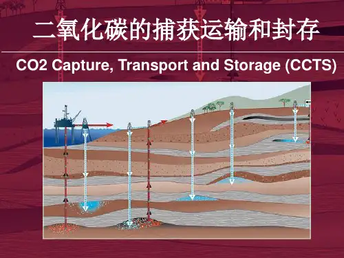
碳的捕集和储存(CCS)技术可以在源头捕集CO2并将其封储在存储设备中,从而减少温室效应。
背景:电力生产中所排放的CO2所占比例最大。
大约60%的排放来自于大型的固定排放源(10万吨CO2/年),使用天然气或煤作为燃料的火电厂大约占其中的30%。
全球大约有2000座年排放量超过100万吨CO2的电站,它们是CO2捕集的最重要的潜在目标。
碳捕集CO2是一种不稳定的气体,要从惰性气体(主要是氮气)中捕集CO2是非常困难的,成本相当高,还需要额外的能量。
由于传统的火电站是在大气压力下燃烧天然气或煤炭,在清洁的惰性气体排放到大气以前,CO2必须在非常困难的条件下分离出来。
这样做的目的是得到浓缩的易于传输的高压CO2气流。
碳捕集的三种方法之预燃烧CO2在燃烧之前分离出来,这一过程比较复杂但潜力巨大。
碳捕集的三种方法之后燃烧CO2从燃烧后的废气中分离出来。
这种方法将电站的能量输出减少了20%以上,但是CCS技术的开发重点目前集中在这一领域。
因为这种方法已经在用,而且现有的电站可以进行更新。
碳捕集的三种方法之全氧燃烧工艺用氧气替代燃烧过程中的空气,因此废气中主要含有CO2和水。
CO2可以通过冷凝分离出来。
现有电站可以根据全氧燃烧工艺的要求进行翻新,这一工艺颇具前景,目前一些示范电站已在建设之中。
碳捕集难题传统火电站的废气率非常高,例如一座400 MW的天然气发电设备废气率超过200万立方米/小时。
另外,高浓缩的溶剂输送到再生塔后释放出CO2,然后稀释的溶剂被输送回吸收塔中。
如何使液体分布器在塔柱交叉部位均匀喷洒是一大难题。
解决方案苏尔寿的液体分布器测试装置可以解决这些难题。
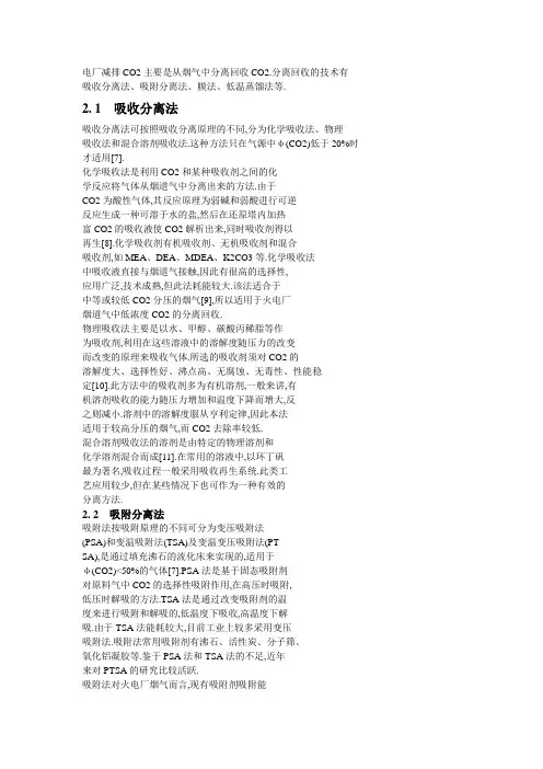
An intelligent system for monitoring and diagnosis of the CO 2capture processQing Zhou a ,Christine W.Chan a ,⇑,Paitoon Tontiwachwuthikul ba Energy Informatics Laboratory,Faculty of Engineering,University of Regina,Regina,Saskatchewan,Canada S4S 0A2bProcess Systems Engineering Laboratory,International Test Centre for CO 2Capture (ITC),University of Regina,Regina,Saskatchewan,Canada S4S 0A2a r t i c l ei n f o Keywords:CO 2capture DeltaV Simulate Intelligent systema b s t r a c tAmine-based carbon dioxide capture has been widely considered as a feasible ideal technology for reduc-ing large-scale CO 2emissions and mitigating global warming.The operation of amine-based CO 2capture is a complicated task,which involves monitoring over 100process parameters and careful manipulation of numerous valves and pumps.The current research in the field of CO 2capture has emphasized the need for improving CO 2capture efficiency and enhancing plant performance.In the present study,artificial intelligence techniques were applied for developing a knowledge-based expert system that aims at effec-tively monitoring and controlling the CO 2capture process and thereby enhancing CO 2capture efficiency.In developing the system,the inferential modeling technique (IMT)was applied to analyze the domain knowledge and problem-solving techniques,and a knowledge base was developed on DeltaV Simulate.The expert system helps to enhance CO 2capture system performance and efficiency by reducing the time required for diagnosis and problem solving if abnormal conditions occur.The expert system can be used as a decision-support tool that helps inexperienced operators control the plant;it can be used also for training novice operators.Ó2010Elsevier Ltd.All rights reserved.1.IntroductionThe emission of large amounts of carbon dioxide (CO 2)has caused increasing public concern regarding environmental pollu-tion and global warming.To mitigate this serious environmental problem,the CO 2capture technology has become widely accepted as useful technology for reducing CO 2emissions from industrial sources.The goal of CO 2capture is to capture and remove CO 2from industrial gas streams before it is released into the atmosphere.The amine-based CO 2capture process has become a common method for CO 2removal because it is energy efficient (Sholeh,Svendsen,Karl,&Olav,2007).In the amine-based CO 2capture pro-cess,an amine solvent is used to absorb CO 2from the flue gas,and CO 2is subsequently extracted from the amine solvent,which can then be regenerated and reused.Operation of an amine-based CO 2capture system is a complicated task because it involves mon-itoring and manipulation of 16components and a number of valves/pumps.The 16components are associated with over a 100parameters,including temperatures,flow rates,pressures,and levels of reaction instruments.The monitoring and control of crit-ical parameters is an important task in operation of the CO 2cap-ture process because it directly impacts plant performance and capture efficiency of CO 2.Since the monitoring and control task is complex,it is desirable to build a knowledge-based system that can automatically monitor,control,and diagnose the CO 2capture process.In this paper,we present research conducted with the objective of building a knowledge-based expert system that can monitor,control,and diagnose the CO 2capture processes at the International Test Centre for CO 2Capture (ITC)located at the University of Regina in Saskatchewan,Canada.The system is called the Knowledge-Based System for Carbon Dioxide Capture (KBSCDC).The knowledge base consists of domain knowledge about:(1)the plant components and their attributes,and (2)the important process parameters and their desired operat-ing ranges.The knowledge base also consists of the remedial actions that would address these abnormal situations.The KBSCDC system can help the operator monitor the operating conditions of the CO 2capture pilot plant by continuously comparing the mea-sured values from sensors with normal or desired values.Plant components that have abnormal parameter values indicate that abnormal operating conditions have occurred.Deviations from the normal ranges would set off an alarm to advise the operator that a problem has occurred.The KBSCDC can conduct real-time monitoring and diagnosis,as well as suggest remedies for any abnormality detected,thereby improving the performance effi-ciency of the plant.An initial prototype of the system was developed on G2(trade-mark of Gensym Corporation,USA),which is an object-oriented expert system development tool.However,the prototype can only monitor reaction instruments and diagnose their abnormalities.The system did not include the process control strategies applied0957-4174/$-see front matter Ó2010Elsevier Ltd.All rights reserved.doi:10.1016/j.eswa.2010.12.010⇑Corresponding author.Tel.:+13065855225;fax:+13065854855.E-mail address:christine.chan@uregina.ca (C.W.Chan).to the control devices.Details of the prototype system have been presented in Zhou,Chan,and Tontiwachiwuthikul(2009).This pa-per presents an improved version of the knowledge-based expert system that was implemented with DeltaV Simulate(trademark of Emerson Corp.,USA).DeltaV Simulate provides control utilities which enables the configuration of control strategies in small mod-ular components.These modules link algorithm,conditions,and provide control over thefield devices such as pumps and valves. Modules can communicate directly with each other,and can be coordinated by other modules to perform higher-level control strategies.The modules deploy different algorithms such as sequential function chart(SFC)and function block diagram(FBD). SFC is made up of a series of steps,transitions,and actions and it is used for representing the sequence of controlling strategies which contain multiple states.FBD is made up of interconnected function blocks,which process the incoming signals and send the signal to the control devices.Each function block contains standard process control algorithm and parameters that customize the algo-rithm to perform a particular function in the process control. Therefore,the new version of KBSCDC has the following additional functions compared to the earlier G2version:(1)modules for dif-ferent control devices are configured based on their characteristics, and(2)the control strategies applied to the control devices are simulated.The paper discusses design and development of the improved version of the knowledge-based system,and demonstrates use of the system by using problems scenarios that occur due to abnor-mal conditions.The paper is organized as follows:Section2pre-sents the background literature relevant to the area of CO2 capture and the knowledge acquisition approach of the inferential modeling technique adopted in this research.Section3describes the process of development of the knowledge base.Section4pre-sents design and implementation of the system on DeltaV Simu-late based on the developed knowledge base.Application of the system is demonstrated using a case study in Section5.Section 6gives a conclusion and includes some discussion about future work.2.Background literature2.1.Studies of amine-based CO2captureThe study of amine-based CO2capture has been ongoing for the last decade.The general objective of the study is to improve effec-tiveness and efficiency of the CO2capture process.The research has been primarily conducted in the following two areas:(1)Study of the behaviour of the conventional amine solventsand development of new or improved solvents with higher CO2absorption capacities,faster CO2reaction rates, higher degradation resistance,and lower heat consump-tion for regeneration.The studies of corrosion were con-ducted in CO2absorption systems using different types of aqueous amine solvents including methyldiethanol-amine(MDEA),diethanolamine(DEA),2-amino-2-methyl-1-propanol(AMP)and monoethanolamine(MEA),and it was found that the corrosiveness increased in the order of MDEA<DEA<AMP<MEA(Veawab,Tontiwachwuthikul, &Bhole,1997;Veawab,Tontiwachwuthikul,&Chakma, 1999).It was suggested that2-(2-aminoethyl-amino)eth-anol(AEEA)is a potentially good absorbent for capturing CO2because of its high absorption rate and high absorp-tion capacity(Sholeh et al.,2007).Chakma(1997)pro-posed that utilization of mixed solvents could reduce energy consumption and solve a number of operationalproblems.Idem et al.(2006)evaluated the benefits of using mixed MEA/MDEA solvent for CO2capture and found that a very large heat-duty reduction could be achieved by using a mixed MEA/MDEA solvent instead ofa single MEA solvent.(2)Selection of appropriate solvents for different applications toreduce the energy penalty.It was proposed that the crucial criteria of solvent selection include feed gas characteristics such as composition,pressure,temperature,and the treated gas specifications(Veawab,Aroonwilas,Chakma,& Tontiwachwuthikul,2001).White,Strazisar,Granite,and Hoffman(2003)suggested that solvent selection is influ-enced by solvent characteristics such as CO2absorption capability and rates and operational issues of the process such as corrosion potential and solvent stability.These fac-tors influence the equipment size,solvent consumption and heat consumption.Tontiwachwuthikul(1996)proposed that the best solvents can be formulated by blending differ-ent amines to take full advantage of the desirable properties of each solvent.Some observations that can be derived from our survey of past research conducted in thefield of CO2capture include the following:(1)With respect to the objective of improving efficiency of theCO2capture process,previous research studies rarely focused on using automation for supporting the process of monitoring and control of the CO2capture system as a means for optimizing the plant performance and enhancing efficiency of the CO2capture process.Operation of a CO2cap-ture system is a complicated task because it involves control of over100parameters.If these parameters are monitored and controlled effectively,the entire plant can work under desirable conditions and efficiency of the CO2capture pro-cess can be greatly enhanced.(2)Application of artificial intelligence technologies has notbeen made to the CO2capture domain.Since operation ofa CO2capture system is extremely complicated,the processoperators have accumulated significant knowledge and problem-solving skills over time.This experience is exclu-sive and hard to develop,and it is desirable to capture and encode the human expertise into a knowledge-based system for documentation and training purposes.Therefore,the objective of this study is to develop a knowledge-based system for monitoring and control of the CO2capture pro-cess.Such a research study would helpfill the gap in research for thefield of CO2capture process.2.2.Inferential modeling techniqueAn important prerequisite for developing a knowledge-based system is to acquire expertise that can be encoded in the knowl-edge base.For acquiring knowledge on the CO2capture process, we adopted the inferential modeling technique,which is derived from the inferential model.An inferential model is a generic cate-gorization of knowledge types.It functions as a‘‘conceptual map’’to aid the knowledge engineer to identify and classify elements of the elicited expertise(Chan,Tontiwachwuthikul,&Cercone,1995). Based on this map,the inferential modeling technique or IMT supports‘‘an iterative-refinement of knowledge elements in a problem-domain that provides top-down guidance on the knowl-edge types required for problem solving’’(Chan,Peng,&Chen, 2002).The resulting inferential model consists of the following four levels of knowledge:7936Q.Zhou et al./Expert Systems with Applications38(2011)7935–7946(1)Domain knowledge consists of objects,attributes,values,and relations.The objects include a set of concrete domain objects.The attributes describe the properties of the objects, which can be defined as a set of functions that receive input values and return output values.The relations describe the relationships among the objects or the attributes.(2)Inference knowledge consists of abstract objects.Theseinference level objects can be described with inference rela-tions and strength of inferences.The inference relations identify different types of relations among sets of abstract objects;the strength of the inference is associated with each inference relation and represents the relative inferential sig-nificance of the relation.(3)Task knowledge consists of a set of procedures or behaviourswhich are performed to complete a goal.A task is accom-plished by means of a method that invokes the domain and inference objects or relations involved in this task.One task can be decomposed into a number of subtasks,and the objective of this task is accomplished by coordinating all the sub-goals.(4)Strategy knowledge is defined as the knowledge used duringthe diagnostic process to decide what is the most opportune choice to make or,alternatively,to judge if it is worth exe-cuting a certain action with respect to other possible actions (Mussi,1993).The IMT was applied and the templates of domain knowledge and task knowledge were used in the process of knowledge base development for the domain of amine-based CO2capture process.2.3.Amine-based CO2capture processThe goal of CO2capture is to separate CO2from industrial gas streams before they are released into the atmosphere.The process of amine-based CO2capture at the International Test Centre for CO2capture(ITC)can be briefly described as follows:prior to CO2capture,theflue gas is cooled down and particulates and other impurities such as SO x and NO x are removed as much as possible. The pre-treatedflue gas is injected into the absorber column from the bottom,and it contacts solvent that is free of CO2or lean amine solvent,which is injected from the top of the absorber column.The amine selectively absorbs CO2from theflue gas.The amine solvent carrying CO2,which is called CO2-rich or rich amine,enters the stripper column,where the CO2is extracted from the amine sol-vent and the lean amine solvent is regenerated.The lean amine sol-vent is returned to the absorber column and used in the CO2 removal process again.The CO2stream produced is dried and post-treated,and it can be either developed to a food grade quality or pressurized and transported to a suitable site for geological stor-age.The CO2capture process is depicted in Fig.1.3.Development of a knowledge baseThe knowledge base in this study was developed in three phases:knowledge acquisition,knowledge analysis,and knowl-edge representation.In the process of knowledge acquisition,the first author acted as the knowledge engineer and interacted with the domain expert,who is the chief engineer of ITC,to acquire knowledge about problem-solving in the domain.The process of knowledge acquisition lasted1year,from January to December 2005.During the phases of knowledge analysis and representation, the knowledge engineer analyzed the verbal information collected from the expert and configured them into a conceptual model.The IMT was applied in knowledge analysis,and the knowledge was formalized into an inferential model.The IMT decomposed knowl-edge into the two levels of domain knowledge and task knowledge.3.1.Domain knowledgeDomain knowledge includes three components:the objects, their attributes,and values related to the attributes.The objects in the plant can be classified into two categories: static and dynamic.The static objects include the constructive components of the plant,which can be divided into the three classes of reaction instruments,valves,and pumps.The dynamic objects include the substances that circulate and react in the plant, i.e.,the water,amine solvent,and gases.The classification of ob-jects is shown in Fig.2,and the details are described in the follow-ing sections.3.1.1.Static objects and their attributesThe three kinds of static objects including reaction instruments, valves and pumps are discussed in details as follows.3.1.1.1.Reaction instruments.There are16primary reaction instru-ments involved in the plant.They are grouped into three main clas-ses based on their functions and listed as follows:(1)Pre-treatment section,which includes the steam boiler,micro turbine,inlet-gas scrubber.(2)Absorption-based CO2section,which includes the absorber,off-gas scrubber,lean amine storage tank,lean amine cooler,rich amine vessel,lean/rich amine exchanger,strip-per,reboiler,and reclaimer.(3)Post-conditioning section for product purification,whichincludes the reflux condenser,reflux accumulator,CO2wash scrubber,and CO2dryer unit.The attributes of the reaction instruments include the tempera-ture,pressure,or level of the instruments and the attributes of their output dynamic objects.The details of the attributes of the reaction instruments will be discussed in Section3.1.2.3.1.1.2.Valves and pumps.The valves and pumps are manipulated to control the process parameters.Therefore,all the pumps and valves are associated with the attributes of the reaction instru-ment.In terms of representation in the knowledge hierarchy,the reaction instruments’attributes are represented one level below the reaction instrument objects.Corresponding to this representa-tion,the pumps and valves are defined as modules in the system design because the modules are one level lower than the plant area in the DeltaV representational hierarchy.Valves:The valves can be categorized into two types based on their control mechanism:PID(proportional-integral-derivative) control valves and solenoid valves.While all the solenoid valves are used for controlling waterflow,the PID valves can be subdi-vided into four groups based on the substances they manipulate: (1)steam supply control valve,(2)amine control valve,(3)water control valve,and(4)gas control valve.All the PID control valves in the plant can be identified byfive attributes:the three system attributes of:(1)tag number(the label for a valve/pump),(2)name(the brief description),(3)type(the mechanism of a valve/pump),and two design attributes of(4)loca-tion(where the valve/pump is installed in the plant),and(5)distri-butionflow(the dynamic object which a valve/pump controls).The solenoid valves can be identified by the additional attribute of sta-tus,which describes their ON/OFF state under normal conditions. Also,the attribute of distributionflow determines the process parameter controlled by a valve,and the attribute of locationQ.Zhou et al./Expert Systems with Applications38(2011)7935–79467937determines the plant area to which a valve belongs in the phase of system design.Pumps:Pumps include liquid distribution pumps and gas blower pumps.The liquid distribution pumps can be divided into three subclasses according to the types of flow they control:(1)water control pumps,(2)amine control pumps,and (3)chemical flow control pumps.Like solenoid valves,all the PID control valves in the plant can be identified by six attributes including tag num-ber,name,type,location,distribution flow,and status.A sample valve and a sample pump are given in Table 1. 3.1.2.Dynamic objects and their attributesThe dynamic objects include amine solvent,water,and gas.The amine solvent can be classified into lean amine and rich amine based on the amount of CO 2it carries.The gases include flue gas (with CO 2),off gas (free of CO 2),CO 2,and steam.All the dynamic objects can be specified by the three attributes of temperature,pressure,and flow rate.Since the dynamic objects circulate and react through the entire process,the values of their attributes are constantly changing.Therefore,a decision was made to identify the properties of dynamic objects at anyparticularFig.1.Amine-based CO 2capture process flow diagram.CO 2 Capture PlantStatic ObjectsWaterDynamic ObjectsReaction InstrumentsGasesPumps ValvesSolventFlue Gas Off Gas CO 2SteamRich AmineLean AmineFig.2.Objects in CO 2capture plant.location with the tag of the sensor.Moreover,the knowledge engi-neer classified the attributes of the dynamic components with the attributes of the reaction instrument from which theyflow.For example,the attributes of the lean amine storage tank include the level and temperature of the tank itself,as well as the attri-butes of its output lean amine.They include:(1)amine storage tank level(DPT-600),(2)lean amine storage tank temperature (TE-640),(3)lean amine to absorberflow rate(FT-600),and(4) lean amine to absorber temperature(TE-600).The attributes of dynamic objects are organized in this way due to three reasons.Firstly,the performance of the reaction instru-ment directly influences the attributes of its output dynamic ob-jects;hence,it is logical to group the reaction instrument with the output dynamic objects.Secondly,this approach enables straightforward examination of the attributes of dynamic objects at different phases in the process.Thirdly,this organization simpli-fies the grouping of attributes and facilitates design and construc-tion of the KBSCDC.In this way,over100process parameters in the plant can be grouped into16reaction instrument groupings. Therefore,the entire system can be viewed in terms of16reaction components,their relevant attributes or process parameters,and the relevant valves/pumps.The values of the process parameters are monitored by the system so that if any abnormal value is de-tected,the relevant pump/valves will be manipulated to remedy the abnormal conditions.3.2.Task knowledgeThe objective of the KBSCDC is to maintain normal plant perfor-mance so that it produces CO2at the desired rate.Therefore,the main task of the system is to monitor all the reaction instruments and ensure they operate under desirable conditions.The instru-ments that have abnormal parameter values indicate that abnor-mal operating conditions have occurred.The system can monitor the operating conditions of the CO2capture plant by constantly comparing the measured values with desired parameter values. Deviation from the normal ranges of values triggers an alarm to ad-vise the operator that a problem has occurred.The system then diagnoses the abnormal state and suggests the remedial control ac-tions that would address the abnormal situation.The task of monitoring each reaction instrument includes the subtasks of monitoring its related attributes,i.e.,process parame-ters.Therefore,it is important to obtain the desirable operating ranges of the process parameters.The knowledge engineer identi-fied25critical process parameters and their normal operating ranges with the help of the domain expert;two sample parameters of the inlet-gas scrubber and their normal ranges of values are shown in Table2.Therefore,monitoring of the inlet-gas scrubber consists of the four subtasks of:(1)controlling theflow rate offlue gas into absor-ber(FT-200),(2)controlling the temperature offlue gas into absor-ber(TE-201),(3)controlling the wash waterflow rate of scrubber (FT-420),and(4)controlling the inlet-gas scrubber water level (LC-410).The two sample subtasks of controlling the water level (LC-410)and controlling the wash waterflow rate(FT-420)are dis-cussed here.They are controlled so that the parameter values fall within the values specified in Table2.If the values should fall out-side the normal ranges,the diagnosis and remedial control actions are determined by various conditions.The details of diagnosis and control actions for the sample parameter of wash waterflow rate (FT-420)are given in Table3.If the wash waterflow rate(FT-420)of the inlet-gas scrubber is less than5.0kg/m,a warning is given to the operator.The diagnosis of the situation is that the over lowflow rate of wash water could be caused by the closed water circulation pump P-420.Therefore,the remedial control action is to open pump P-420to restart water circulation between the water tank and the inlet-gas scrubber.However,if P-420is already open, then the PID valve FCV-420should be opened to increase water flow.4.System design and implementation4.1.System designThe intelligent system of KBSCDC was implemented on DeltaV Simulate(a trademark of Emerson Corp.,USA).DeltaV Simulate logically decomposes the entire system into plant areas and control modules.It supports various algorithms for implementing process control logic,and it allows the simulation of dynamic processes and real-time monitoring.The implementation of KBSCDC on DeltaV involves a hierarchy of 5levels:plant area(level1),module(level2),algorithm(level3), function block(level4),and parameter(level5).The hierarchy is shown in Fig.3.The plant areas are logical divisions of the process control sys-tem,which can be based on physical plant locations or main pro-cess functions.A plant area consists of modules,and each module is a logic control entity responsible for configuring the con-trol strategies.It contains algorithms,alarms,and other character-istics that define the process control.Algorithms define the logic steps that describe how the module behaves and how the tasks are accomplished.In this intelligent system,the function block dia-grams(FBD)were used to continuously execute control strategies. The basic component of a FBD is a function block,which contains the control algorithm and defines the behaviour of the module. Each function block contains parameters which are the user-defined data manipulated by the module’s algorithm in its calcula-tions and logic.Thefive-level hierarchy of the KBSCDC system supports a top-down approach for encoding knowledge into DeltaV Simulate. System construction on DeltaV Simulate can be explained by describing sample components of each level as shown in Fig.4, and the details are described below.Three sample plant areas include the stripper,inlet-gas scrub-ber,and absorber.In this discussion,the inlet-gas scrubber is used as an example to illustrate how a plant area is constructed.TheTable1Samples of valve/pump.Tag Name Type Distributeflow Location StatusFCV-600(valve)Lean amine to absorber control valve PID control valve Amine solvent Between absorber and lean amine storage tank N/A B-200(pump)Inletflue gas blower Gas blower Flue gas Betweenflue gas scrubber and absorber ONTable2Sample parameters and their normal operating ranges.Tag Parameter Unit Limit ValueFT-420Off gas scrubber wash waterflow rate kg/min High37.0Low 5.0LC-410Off gas scrubber water level control%High65.0Low 5.0Q.Zhou et al./Expert Systems with Applications38(2011)7935–79467939plant area of inlet-gas scrubber contains eight modules.Four of these are PID valve control modules for the process parameters of:(1)flue gasflow rate into absorber(FC-200),(2)inlet-gas scrub-ber water level control(LC-410),(3)temperature offlue gas to ab-sorber(TC-201),and(4)wash waterflow rate of inlet-gas scrubber (FC-420).The other four are2-state control modules for the pumps and solenoid valves of:(1)flue gas blower(B-200),(2)make up water control valve(EV-300),(3)wash water control valve(EV-420),and(4)wash water pump(P-420).The algorithm used in the module of wash waterflow rate into absorber(FC-420)is represented in a function block diagram,which consists of the function blocks of data input simulation,data output simulation, and primarily a PID control function.Since the KBSCDC system is not connected to the CO2capture plant at the current stage,the data input and output to the system are simulated by using func-tion blocks.The PID control function block contains the most important parameters,which includes the set-point(SP)of the PID control and alarm activation limits,whose variable names in the system are HIGH_LIMIT and LOW_LIMIT.The details of system construction and implementation are given in Section4.2.More implementation details about the knowledge hierarchy of the KBSCDC in DeltaV Simulate are explained as follows.Fig.5 shows how the system knowledge base was developed in the Del-taV system.In Fig.5,the white boxes on the left side contain the components of the knowledge base.As observed vertically from the top to bottom,the components of the domain knowledge con-sist of objects,the attributes of the objects,and values of the attri-butes.The blue or shaded boxes on the right side contain the components of the DeltaV Simulate.As observed vertically,the components of the DeltaV Simulate are also displayed from the higher to lower hierarchical level from the top to bottom(refer to Fig.3).More details on how the knowledge components are rep-resented as the components of the DeltaV Simulate at different lev-els are given as follows:Level1:The objects of the plant include the reaction instru-ments,pumps,and valves.The reaction instruments are defined as the plant area in DeltaV Simulate.Since the CO2capture plant contains16reaction instruments,there are together16plant areas defined in the system.Level2:As mentioned in Section3.1.1.2,the attribute of location of a valve or pump determines the plant area to which a valve or pump belongs in the system design.Each plant area can consist of a number of valves and pumps which manipulate multiple attributes of this plant area.Therefore,the objects of pumps and valves are defined as modules under the level of plant area in the DeltaV Simulate,although they are at the same level of objects as the reaction instruments in the knowledge base.As mentioned in Section3.1.1.2,the pumps and valves have two different control mechanisms of PID control and two-state control.Therefore,the pumps and solenoid valves based on a two-state control mechanism are defined as two-state control modules;the PID control valves are defined as proportional-integral-derivative or PID control modules.Level3:The function block diagram(FBD)is a diagram that con-tains multiple interconnected function blocks.However,since FBD represents a type of algorithm and is not directly related to the knowledge base,it is not shown in Fig.5.Level4:A function block is a logic processing unit that defines the behaviour of an algorithm for a particular module.Two types of function blocks are available:the two-state function block and the PID control function block.At this level,the attri-butes of the objects in the knowledge base are analyzed.As mentioned in Section3.1.1.1,the attributes of a reaction instru-ment include the attributes of the reaction instrument and the attributes of its output dynamic objects,such as the pressure and temperature.Since the PID control valves are used to con-trol the attributes of the reaction instruments and the dynamic objects,the attributes of reaction instruments and dynamic objects and their relative PID control valves are combined into the PID control function blocks,which enable the present values of the attributes to approach their desired values by controlling the PID valves.As mentioned in Section3.1.1.2,the pumps and solenoid valves have another important attribute of status, which manipulate the attributes of the reaction instruments by switching between the ON/OFF states.Therefore,the pumpsTable3Diagnosis and control strategies for sample parameter of inlet-gas scrubber.Object Task Conditions Diagnosis and controlling actionsInlet-gasscrubber Control wash waterflow rate(FT-420)5.0kg/min<=FT-420<=37.0kg/minNormal operationNo action takenFT-420<5.0kg/min Warning is givenDiagnosis:The wash waterflow to water tank is low or stopped by the closed water circulationpump-420Remedial control action:Open P-420to restart water circulation between water tank and scrubber;otherwise,open up FCV-420to increase volume of water returning to water tank if P-420is open FT-420>37.0kg/min Warning is givenDiagnosis:The volume of wash water between the off gas scrubber and water storage tank is toohighRemedial control action:Close FCV-420to reduce wash waterflow from the scrubber wash water storage tank7940Q.Zhou et al./Expert Systems with Applications38(2011)7935–7946。
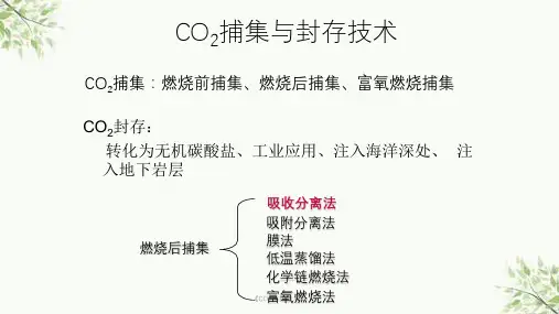
电厂减排CO2主要是从烟气中分离回收CO2.分离回收的技术有吸收分离法、吸附分离法、膜法、低温蒸馏法等.2. 1吸收分离法吸收分离法可按照吸收分离原理的不同,分为化学吸收法、物理吸收法和混合溶剂吸收法.这种方法只在气源中φ(CO2)低于20%时才适用[7].化学吸收法是利用CO2和某种吸收剂之间的化学反应将气体从烟道气中分离出来的方法.由于CO2为酸性气体,其反应原理为弱碱和弱酸进行可逆反应生成一种可溶于水的盐,然后在还原塔内加热富CO2的吸收液使CO2解析出来,同时吸收剂得以再生[8].化学吸收剂有机吸收剂、无机吸收剂和混合吸收剂,如MEA、DEA、MDEA、K2CO3等.化学吸收法中吸收液直接与烟道气接触,因此有很高的选择性,应用广泛,技术成熟,但此法耗能较大.该法适合于中等或较低CO2分压的烟气[9],所以适用于火电厂烟道气中低浓度CO2的分离回收.物理吸收法主要是以水、甲醇、碳酸丙稀脂等作为吸收剂,利用在这些溶液中的溶解度随压力的改变而改变的原理来吸收气体.所选的吸收剂须对CO2的溶解度大、选择性好、沸点高、无腐蚀、无毒性、性能稳定[10].此方法中的吸收剂多为有机溶剂,一般来讲,有机溶剂吸收的能力随压力增加和温度下降而增大,反之则减小.溶剂中的溶解度服从亨利定律,因此本法适用于较高分压的烟气,而CO2去除率较低.混合溶剂吸收法的溶剂是由特定的物理溶剂和化学溶剂混合而成[11].在常用的溶液中,以环丁矾最为著名,吸收过程一般采用吸收再生系统.此类工艺应用较少,但在某些情况下也可作为一种有效的分离方法.2. 2吸附分离法吸附法按吸附原理的不同可分为变压吸附法(PSA)和变温吸附法(TSA)及变温变压吸附法(PT-SA),是通过填充沸石的流化床来实现的,适用于φ(CO2)<50%的气体[7].PSA法是基于固态吸附剂对原料气中CO2的选择性吸附作用,在高压时吸附,低压时解吸的方法.TSA法是通过改变吸附剂的温度来进行吸附和解吸的,低温度下吸收,高温度下解吸.由于TSA法能耗较大,目前工业上较多采用变压吸附法.吸附法常用吸附剂有沸石、活性炭、分子筛、氧化铝凝胶等.鉴于PSA法和TSA法的不足,近年来对PTSA的研究比较活跃.吸附法对火电厂烟气而言,现有吸附剂吸附能力和对CO2选择性较差,从而导致能耗巨大、成本太高[12].若烟道气含CO2量较低,需大量的能量去压缩无用组分来满足吸附压力而且需预处理烟气中的和颗粒物.所以,其更适合于φ(CO2)为20% ~80%的工业气.2. 3膜法膜法可以分为膜分离法和膜吸收法2类.膜分离法是依靠待分离混合气体与薄膜材料(如醋酸纤维、聚酰胺PI、聚矾、聚砜[13-14])间产生的不同化学或物理反应,使某种组分可快速溶解并穿过薄膜,从而将混合气体分成穿透气流和剩余气流2部分.其分离能力取决于薄膜材料的选择性以及穿透气流对总气流的流量比和压力比.主要优点为操作程序简单,高选择性和高稳定性,但缺点是薄膜耐久性差,且分离效率低,因此需要使用2段以上的薄膜分离程序,才能达到一定的分离效率[15].另外受其自身材质的影响,这类膜在高温、高腐蚀性环境中的应用还受一定的限制,在使用过程中容易老化,不大适合于矿物燃料燃烧产生的气体脱除[16],适合处理含量较高的气体.膜分离法非常适用于天然气的处理.膜吸收法是一种将膜分离法和化学吸收法优点相结合的方法.膜吸收法中,在薄膜的一侧有化学吸收液存在,气体和吸收液不直接接触, 2者分别在膜两侧流动,膜本身对气体没有选择性,只起隔离气体和吸收液的作用,膜壁上的孔径足够大,气相组分在驱动力(浓度差)作用下,从气相主体扩散通过气相边界层,到达膜壁,再通过膜孔扩散至液相边界层,通过吸收液的选择性吸收达到分离气体某一组分的目的[17-19].由于吸收液不和烟气直接接触,就克服了化学吸收法中起泡、携带等问题,也解决了膜分离法中烟道气脱除CO2压差不够的缺点,是一种很有前途的气体分离法.膜吸收法主要采用中空纤维膜接触器进行气体吸收.膜法对φ(CO2)高(80% )的原料气的处理在经济上最有利.在燃煤电厂烟气中CO2分离方面,由于膜材料的选择性低、分离纯度不高等问题,目前还处于试验阶段[3].2. 4低温蒸馏法低温蒸馏法是通过低温冷凝分离CO2的一种物理过程,一般是将烟气多次压缩和冷却,以引起CO2的相变,达到从烟气中分离CO2的目的.低温蒸馏法对于φ(CO2)高(60% )的回收较为经济,适用于油田现场.其优点在于能够产生高纯、液态的CO2,便于管道输送.在未来的IGCC或者O2/CO2烟气循环系统中较有前景[12].从烟道气中回收利用CO2,由于烟气温度高,烟气量大,而压力和CO2含量较低,一般来说,用物理溶剂法、薄膜分离法和低温分离法是不太经济的.t燃烧后捕集主要应用于传统燃煤电厂烟道气中CO2与NOX和SOX的分离.由于电厂排放废气中p(CO2)低、处理量大,且同时含有少量氧.所以此技术路线是以气体净化工业上相当成熟的化学溶剂吸收法工艺为基础的,也是当前仅有的已进入工业规模试验的技术路线[20],并已在天然气工业中应用了60 a.对燃煤电厂而言,燃烧产生的烟气含有很多污染物等杂质,杂质的存在会增加捕集的成本.因此,烟气进行吸收处理前要进行预处理,去除其中活性杂质,如硫、氮氧化物和颗粒物等,否则这些杂质会优先与溶剂发生化学反应,消耗大量的溶剂并腐蚀设备[23].燃烧后CO2捕集可分离出高压高浓度的CO2气流,但能耗较高[21].此外,膜法也可用于燃烧后捕集的工艺路线中.工艺流程见图1.燃烧前捕集技术燃烧前捕集技术主要应用于以气化炉为基础(如联合循环技术IGCC)的发电厂[16], IGCC的工艺路线是煤在压力下与氧或空气发生气化及转化反应生成主要由CO和H2组成的混合气体燃料.待混合气体冷却后,在催化转化器中与水蒸汽发生反应,其中的CO转化为分压较高有利于捕集的CO2,并产生更多的H2[22, 23].然后, CO2被分离出来,H2则作为燃气联合循环系统的燃料送入燃气轮机,进行燃气轮机与蒸汽轮机联合循环发电(图2).许多捕集方法都可用于此项技术, IGCC电厂所产生的CO2浓度较高,可采用选择性不强的气体分离技术如物理溶剂吸收、吸附等技术来分离CO2,从而减少能量消耗.另外,膜法对于能产生高压烟气的综合煤气化联合循环电厂而言,也具有无比的诱惑力,因为它可提供膜法所需的压力和动力,从而节省投资.3. 3富氧燃烧捕集富氧燃烧技术是针对燃煤电厂特点所发展的一种既能直接获得高浓度CO2,又能综合控制燃煤污染排放的新一代CO2减排技术[24-26].富氧燃烧技术也称为O2/CO2燃烧技术,或空气分离/烟气再循环技术.该法用空气分离获得的O2和一部分锅炉烟气循环气构成的混合气体代替空气作为化石燃料燃烧时的氧化剂,来保持熔炉中的温度低于可承受点,以提高燃烧烟气中CO2浓度.此燃烧反应发生在O2/CO2混合气的环境中,其主要步骤为空气压缩分离燃烧、电力产生烟气压缩和脱水.见图3.该技术主要优越性在于[5]: 1)采用烟气再循环,以烟气中的CO2来替代助燃空气中的氮气,与氧气一起参与燃烧,这样能使排烟中的φ(CO2)>95%,可直接回收CO2; 2)SO2、NOx排放低,同时矿物质的蒸发量也可比常规空气燃烧时有显著地下降,是一种污染物综合排放低的环境友好型燃烧方式; 3)烟气再循环使得燃烧装置的排烟量仅为传统方式的1/5,从而大大减少排烟损失,由此锅炉热效率得以显著提高; 4)通过调整CO2的循环比例有可能实现燃烧、传热的优化设计[27-28].该技术的缺点是废气中增加的SO2会腐蚀设备,且技术尚不成熟.3. 4化学链燃烧技术化学链燃烧(Chemical Looping Combustion,CLC)技术是一种基于零排放理念的先进技术,其利用氧载体(通常是金属氧化物)中的氧原子来代替空131气中的氧来完成燃料的燃烧过程.它包括两个串联的反应器:燃料反应器和空气反应器.燃料反应器中(还原反应):燃料+MO(金属氧化物)→CO2+H2O+M(金属);空气反应器中(氧化反应):M(金属)+O2(空气)→MO(金属氧化物).燃料从固体金属氧化物获取氧,无需与空气直接接触.还原反应的生成物为高浓度的CO2、水蒸汽和固体金属M.氧化反应是前一个反应中生成的固体金属与空气中的氧反应,重新生成固体金属氧化物MO.金属氧化物MO与金属M在两个反应之间循环使用,起到传递氧的作用.目前主要的氧载体是金属氧化物,包括Fe、Cu、Ni、Mn、Co等的氧化物.空气反应器中产生的废气是无害的,其大部分为N2.整个过程中不会产生NOX,采用物理冷凝法即可分离回收CO2,从而以较低的能耗实现CO2的高浓度富集[29].3. 5以煤制氢为核心的近零排放技术在此技术中,煤与氢在高温、高压下反应生成甲烷,然后在CaO存在的情况下,甲烷与H2O进行重整反应,生成氢气和CaCO3,其中一部分氢气在系统内循环,另一部分被用作燃料电池的燃料产生电力; CaCO3在高温下煅烧产生高纯度的CO2,CaO则被循环利用.煤在该过程中的生成物只是高纯度的H2和CO2[30].该技术为煤的高效洁净利用提供了极大的发展空间,为减少煤利用过程中温室气体CO2的排放提供了一个崭新的途径.技术流程见图4.该技术中,能量与物质在系统中充分循环.一方面,能够充分利用系统自身的能量维持各过程的进行,从而减小了系统的能量损失,提高效率;另一方面,烟气循环使大量污染物在系统内循环,从而减小了污染物的排放量.由于没有空气参与燃烧,避免了颗粒物和其他污染物的释放[5].。
co2捕集与利用
1. 什么是CO2捕集与利用?
CO2捕集与利用是指利用特定技术将大气中的二氧化碳(CO2)捕集并转化为有用的化学品或燃料。
这种技术可以帮助减少大气中的温室气体排放,从而缓解全球气候变化的影响。
2. CO2捕集技术有哪些?
目前,CO2捕集技术主要包括物理吸附、化学吸收和膜分离三种方式。
物理吸附是指利用吸附剂将CO2从气体中分离出来,化学吸收则是通过化学反应将CO2转化为其他化合物,而膜分离则是利用特定的膜将CO2从气体中分离出来。
3. CO2捕集技术的应用领域有哪些?
CO2捕集技术可以应用于多个领域,包括化工、石油、钢铁、水泥等工业领域,以及发电、交通等领域。
在这些领域中,CO2捕集技术可以帮助降低温室气体排放,减少环境污染,同时也可以实现资源的回收利用。
4. CO2捕集与利用的优势是什么?
CO2捕集与利用的优势在于可以帮助减少温室气体排放,缓解全球气候变化的影响。
此外,CO2捕集与利用还可以实现资源的回收利用,降低生产成本,提高经济效益。
5. CO2捕集与利用的未来发展趋势是什么?
随着全球环境保护意识的不断提高,CO2捕集与利用技术将会得到更广泛的应用。
未来,CO2捕集与利用技术将会更加成熟、高效、经济,同时也会出现更多的应用领域,为人类的可持续发展做出更大的贡献。
二氧化碳的捕集与应用技术二氧化碳(CO2)是一种常见的气体,在大气中占据着重要的位置。
然而,由于人类活动的影响,二氧化碳排放量不断增加,对环境和生态系统造成了严重的影响。
因此,开发二氧化碳捕集和利用技术变得尤为重要。
一、二氧化碳的捕集技术1.化学吸收法化学吸收法是一种常见的二氧化碳捕集技术,主要通过吸收剂捕集二氧化碳。
当二氧化碳从烟气中经过吸收剂时,会与吸收剂发生化学反应,从而降低二氧化碳的排放量。
目前常用的吸收剂包括胺类、碳酸物类和新型吸收剂。
2.物理吸附法物理吸附法又称为压缩吸附法,是通过压缩空气来捕集二氧化碳。
当烟气中的二氧化碳经过吸附剂时,二氧化碳与吸附剂物理吸附,从而减少二氧化碳的排放量。
目前常用的吸附剂包括活性炭、分子筛和氧化锆等。
3.生物降解法生物降解法主要是通过微生物和植物等生物体进行二氧化碳的捕集。
通过调节条件和优化基质,可以增加微生物或植物对二氧化碳的吸收量。
目前常用的微生物包括微生物菌株、藻类和真菌,常用的植物包括橡胶树、青海湖湖滨土壤植物和绿色微环境等。
二、二氧化碳的应用技术1.化学利用化学利用是二氧化碳的一种常见使用方式。
二氧化碳可以与水反应,形成碳酸氢根离子,也可以同一分子反应形成碳酸二酯,是生产化肥、塑料等化学品的重要原料。
2.生物利用生物利用是指通过植物、微生物等生物体将二氧化碳转化为油脂、蛋白质等有机物质。
其中,常见的利用方式包括微生物合成生物柴油、利用植物生产生物质量等。
3.物理利用物理利用是指利用二氧化碳的物理性质,在各个领域进行利用。
例如:利用二氧化碳制作碳化硅、钙质等材料,制冷技术等。
总结综上所述,二氧化碳的捕集和利用是关乎人类未来生存的重大问题。
随着科技的不断进步和环保意识的提高,相信新的捕集和利用技术必将涌现。
二氧化碳捕集与利用关键技术及应用1. 引言嘿,大家好!今天我们来聊聊一个大家都听过,但可能不太了解的话题——二氧化碳捕集与利用。
别担心,不会让你觉得像是在听枯燥的课,咱们就像在茶馆聊天一样,轻松点。
你知道吗?二氧化碳(CO₂)可不是单纯的“坏家伙”,虽然它在气候变化中是个大角色,但如果好好利用,竟然还能变成宝贝呢!所以,今天咱们就来看看这项技术的关键点以及它的应用,走起!2. 二氧化碳捕集技术2.1 什么是二氧化碳捕集?先来搞明白,二氧化碳捕集到底是什么。
简单来说,就是把空气中的二氧化碳抓住,像抓小猫小狗一样,把它们“囚禁”起来。
想象一下,咱们的工厂、发电厂排放的二氧化碳就像是肆意奔跑的小妖怪,捕集技术就是那个勇敢的猎人,把它们一一抓回家。
这个过程有很多种方法,比如化学吸收法、物理吸附法,还有膜分离法等等。
每种方法都有自己的特点,就像不同的调料,各有各的风味。
2.2 关键技术说到技术,那可真是一门大学问。
现在最流行的方式是用一些特殊的材料来吸附二氧化碳。
比如,咱们可以用“活性炭”——这东西就像是个超级吸尘器,能把二氧化碳吸得干干净净。
还有一些新型的材料,像是金属有机框架(MOFs),它们就像海绵一样,能把二氧化碳吸收得特别彻底,真是个“顶尖高手”。
再比如,最近有个叫“直接空气捕集”的技术,听起来酷炫吧?它就是从空气中直接把二氧化碳提取出来,像是把水从河里打上来一样。
3. 二氧化碳的利用3.1 二氧化碳变废为宝咱们捕集到的二氧化碳可不能就这么放着。
要知道,它可是个宝藏!拿它来做什么呢?有些聪明的科学家把它转化成燃料,嘿,这样咱们就能用二氧化碳来发电,真是大开眼界!想象一下,家里的灯泡亮起来,背后却是二氧化碳在发光发热,感觉是不是特酷?此外,二氧化碳还可以用来制造化学品,甚至是塑料,简直是个全能选手。
3.2 应用实例在实际应用上,二氧化碳捕集与利用已经开始展现它的威力。
有些企业已经在采用这些技术,把废气变成新产品。