EDITOR B-C Bj6rk
- 格式:pdf
- 大小:203.72 KB
- 文档页数:12

怎么激活最新010Editor12版本?附激活教程+补丁怎么激活最新的010 Editor16进制编辑器?010 Editor是⼀款专业的⽂本编辑器和⼗六进制编辑器,可以编辑任何⽂本⽂件,包括 Unicode ⽂件、批处理⽂件、C/C++、XML 等编程语⾔,⽽在编辑⼆进制⽂件中,010Editor功能强⼤具有很⼤优势。
⼆进制⽂件是⼀种计算机可读,但⼈很难读懂的⽂件(⼆进制⽂件如在⽂本编辑器中打开将显⽰为乱码)。
⼗六进制编辑器是⼀种程序,它允许您查看和编辑⼆进制⽂件的单个字节,以及包括 010 Editor 的⾼级⼗六进制编辑器还允许您编辑硬盘驱动器、软盘驱动器、内存密钥、闪存驱动器、CD-ROM、系统进程等中的字节等。
今天⼩编给⼤家分享得是010 Editor的安装激活版本,只需要简单的复制粘贴即可免费使⽤全部功能,下⾯有详细的安装激活步骤,需要的朋友不要错过哦!010 Editor 下载地址⼗六进制⽂本编辑器010 Editor v12.0.1 免费破解版附激活教程+补丁 64位类型:编程⼯具⼤⼩:17.67MB语⾔:英⽂软件时间:2021-10-11查看详情010 Editor(⼗六进制⽂本编辑器) v12.0.1 免费破解版附激活教程 32位类型:编程⼯具⼤⼩:16.29MB语⾔:英⽂软件时间:2021-10-11查看详情安装激活教程1.在下载解压后,⼤家将获得010EditorWin64Installer12.0.1.exe和crack等⽂件,双击010EditorWin64Installer12.0.1.exe进⼊安装向导,开始安装软件,如图2.勾选我同意此协议,如图3.点击browse选择软件安装⽬录,默认⽬录:C:\Program Files\010 Editor ;如图4.选择开始菜单⽂件夹:安装程序应该把程序的快捷⽅式放在哪⾥?选择完成后直接next继续安装,如图5.选择额外的任务:应该执⾏哪些附加任务? 默认选择也可以,如图6.点击install开始安装,如图7.等待安装完成,如图8.注意:去掉勾选,先不要运⾏软件,如果已经运⾏软件,请彻底去除,如图9.在安装免费⽂件前,⾸先要打开软件的安装⽬录,如果忘记软件的安装⽬录,请返回到桌⾯,找到软件的桌⾯快捷图标,并右键点击图标,出现弹窗后选择“打开⽂件位置”即可获得⽂件安装⽬录。
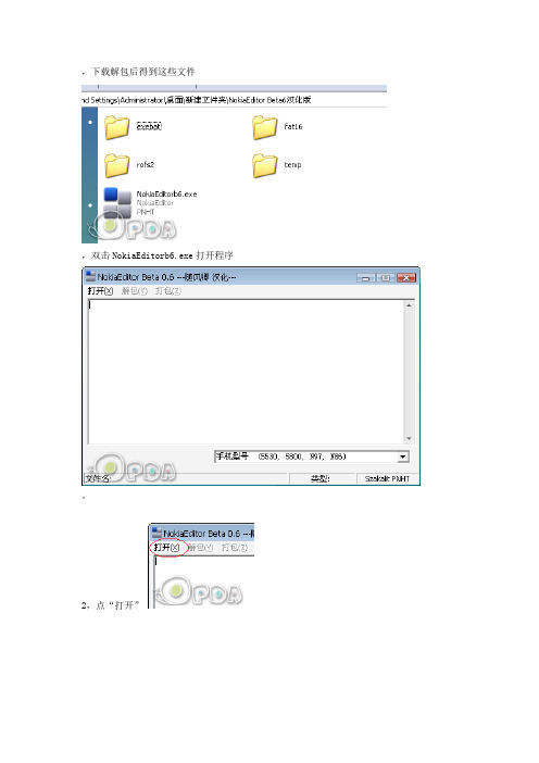
,下载解包后得到这些文件,双击NokiaEditorb6.exe打开程序。
2,点“打开”,在出来的对话框中选择你要修改的固件文件,然后点“解包”。
(注:目前能解开“.uda.fpsx”、“.language.fpsx”和“.core.fpsx”,但只有“.uda.fpsx”和“.language.fpsx”两个文件从新打包后还有效,故CORE暂不在本贴讨论范围。
)3,无论解包的是“.uda.fpsx”还是“.language.fpsx”,都不要现在关闭nbokia editor,最小化在一旁就好。
{:14_344:}4,如果打开的是“.uda.fpsx”,等软件解包完后会在软件目录下的“fat16”文件夹内得到一个“fat16.img”文件,这是C盘的镜像,换句话说这里面包含了所有刷机后出现在你手机C盘的所有文件,可用magiciso或winimage等其他的软件,爱清空的清空,爱修改的修改吧。
理论上全清空了也对手机没影响,而且C盘可用空间还会增大,我自己的N86全清空了刷完机就有65M的可用空间。
{:14_332:}5,如果打开的是“.language.fpsx”,则在软件目录下的rofs2文件夹内得到data、private、resource、sys、System等几个文件夹,这就是刷进Z盘的东西了,固化软件、特效、破解、精减等等等就在这里进行,至于怎么修改,那就不是本贴要说的了,论坛里资料很多,可以搜索看看。
{:14_340:}6,最后,改完fat16或rofs2后,点一下软件的“打包”,等一会就会在软件的根目录下生成一个属于你的固件文件,重命名把“REB-”去掉,把文件覆盖进原来的刷机包就可以开刷了。
(注意:现在只能用JAF强刷。
){:14_350:} {:14_350:} {:14_350:}注:1.目前能解开“.uda.fpsx”、“.language.fpsx”和“.core.fpsx”,但只有“.uda.fpsx”和“.language.fpsx”两个文件从新打包后还有效,故CORE暂不在本贴讨论范围。

FILE(文件) EDIT(编辑) -;Rest(重置) Undo(撤消) uFc+)ASave Selected(保存所选择的对象) Redo(恢复) E XRef Objects(外部参考物体) Clone(复制) 0#^bjXRef Scenes(外部参考场景) Delete(删除) zK'cMerge(合并) Select All(对象选择) fReplace(替换) Select None(取消对象) wImport(输入) Select Invert(对象反转) OVixmExport(输出) Hold(保存) "b9U~Archive(压缩存盘) Fetch(取出) ,)2View File(观看文件) Select BY(根据..选择) @Select By Color(根据颜色..选择)Select By Name(根据名字..选择) "mnf9Region(区域) +m T.9Edit Named Selections(编辑已命名被选物) Sa\J&C Properties(属性) =50qTOOLS(工具菜单) GROUP(分组菜单) 1TeavlMirror(镜像) Group(分组) ~"*Array(阵列) Open(打开) >WrAlign(对齐) Close(关闭) *6pPlace Highlight(放置高亮区) Ungroup(解除群组) X\W< Align Camera(对齐摄像机) Explode(分解) PfUScaping Tool(间距修改工具) Detach(分离) ?c, Transform Type-In(输入变换坐标) Attach(合并) ! Display Floater(显示浮动物体) ^XHide(隐藏) YrhFreeze(冻结) AJSelection Floater(选择浮动物体) tSnapshot(快照复制) eNormal Align(法向对齐) Q~x*mrMaterial Editor(材质编辑器) sMaterial/Map Browser(材质/贴图浏览器) Nr VIEWS(视图菜单) @LUndo(撤消) g#95&mRedo(重复) v,1AkGSave Active View(保存当前激活的视图状态) D Restore Active View(还原当前激活的视图状态) 9n Grids(栅格) o!T=Show Home Grid显示主栅格) :rr|Activate Home Grid(激活主栅格) 6cn$Activate Grid Object(激活栅格对象) G+:p|ALign To View(对齐视图) WmnTzViewport Background(背景图像) b00]/Update Background Transform(更新背景图像) $Rest Background Transform(重设背景转换) +m~M"aShow Transform Gizmo(显示转换范围框) U,Show Ghosting(显示前后帖) MOK>SjShow Key Times(显示轨迹点时间) ?6zD/fShade selected(阴影选择) Hj\Show Dependencies(显示从属物体) b})Instances(相依物体) vReference(参考物体) U#%IAkMatch Camera To View(相机与视图相配) ;|Add Default Lights To Scene(向场景添加缺省灯光) 'Redraw All Views(重画所有的视图) KeVDeactivate All Maps(休眠所有贴图) RQ>xaAUpdate During Spinner Drag(微调控制项拖动时更新) 4wdf7}Expert Mode(专家模式) FkTqH┪绶够ブ槔致厶-- READY TO(饭)- 午(饭)33 Object(物体工具栏) Create(创建命令面板) D_nyCompounds(复合工具栏) Modify(修改命令面板) 2RLighes&Cameras(光线和照相机工具栏) Hierarchy(层级命令面板) v Particles(粒子系统工具栏) Motion(运动命令面板) `~nHelpers(帮助物体工具栏) Display(显示命令面板) ]Space Warps(空间扭曲工具栏) Utilities(实用程序) ,NModifiers(修改工具栏) )aLpRendering(渲染工具栏) uCG!7Shapes(二维图形工具栏) G<Modeling(造型修改工具栏) 2d┪绶够ブ槔致厶-- READY TO(饭)- 午(饭) t| MODIFIER STACK(编辑修改器堆栈) 布尔运算与克隆对象KjPin Stack(钉住堆栈状态) Union(并集) LrActive/Inactive(激活/不激活切换) Subtraction(差集) y5:Show End Result(显示最后结果) Intersection(交集) 6!kv7Make Unipue(使独立) Copy(复制) i)ByRemove Modifier(删除编辑修改器) Instance(关联复制) *46Edit Stack(编辑堆栈对话框) Reference(参考复制) 0T┪绶够ブ槔致厶-- READY TO(饭)- 午(饭))y'& 材质编辑器Reglection(反射) J8Basic Parameters(基本参数) Refraction(折射) `!.Ambient(环境反射) 3D Procedural Maps(三维贴图) )2.Diffuse(漫反射) Face-mapped(面贴图) Ne)}Specular(镜面反射) eExtended Parameters(扩展参数) _O1Maps(贴图) }.Bitmap(位图) +)62d.Checker(棋盘格) 复合材质::ceN%.Gradient(渐变) Double Sided(双面) "|.Adobe Photoshop Plug-In Filter(PS滤镜)Blend(混合) t%=hi9.Adove Premiere Video Filter(PM滤镜) Matte/Shoadow() $fu.FZ .Cellular(细胞) Multi/Sub-object(多重子物体) W3zD(.Dent(凹痕) Raytrace(光线追踪) ~).Noise(干扰) Top/Bottom(项底) Hmv.Splat(油彩) [.Matrble(大理石) nciD.Wood(木纹) q3y/D.Water(水) Time Configuration(时间帧速率) h.Falloff(衰减) Frame Rate(帧速率) -.Flat Mirror(镜面反射) NTSC(NTSC制式) }V.p.Mask(罩框) Film(胶片速度) 9J#.Mix(混合) PAL(PAL制式) w8.Output(输出) Custom(自定义) uR&uI.Planet(行星) 6.Raytrace(光线跟踪) 1.Reglect/Refrace(反射/折射) ts>gd.Smoke(烟雾) Create(创建) ``8B=.Speckle(斑纹) Helpers(帮助物体) Ka&W#.Stucco(泥灰) Dummy(虚拟体) j!I.Vertex Color(项点颜色) Forward Kinematics(正向运动) 8{nha: .Composite(合成贴图) Inverse Kinematics(反向运动) M.Particle age(粒子寿命) 11e:.Patticle Mblur(粒子模糊) ayCreate Section Curve(生成截面曲线) CSYS(坐标系)3D MAX命令翻译FILE(文件) E DIT(编辑)Res t(重置) U ndo(撤消)Save Selected(保存所选择的对象) Redo(恢复) XRef O bj ec ts(外部参考物体) C lone(复制)XRef Scenes(外部参考场景) Delete(删除) Merge(合并) Select A ll(对象选择)Replace(替换) Selec t None(取消对象)I mport(输入) Selec t I nvert(对象反转)Export(输出) H old(保存)Arc hive(压缩存盘) Fetc h(取出)View File(观看文件) Selec t BY(根据..选择) Selec t By C olor(根据颜色..选择)Selec t By Name(根据名字..选择)Region(区域)E dit Named Selec tions(编辑已命名被选物)P roperties(属性)TOOLS(工具菜单) GROUP(分组菜单)Mirror(镜像) Group(分组)Array(阵列) O pen(打开)Align(对齐) C lose(关闭)Place Highlight(放置高亮区) U ngroup(解除群组) Align C amera(对齐摄像机) E xplode(分解)Sc aping T ool(间距修改工具) Detac h(分离)T rans form Type-I n(输入变换坐标) A ttac h(合并) Display Floater(显示浮动物体) YH ide(隐藏)Freeze(冻结)Selec tion Floater(选择浮动物体)Snapshot(快照复制)N ormal A lign(法向对齐)Material E ditor(材质编辑器)Material/Map Brow s er(材质/贴图浏览器)VIEWS(视图菜单)U ndo(撤消)Redo(重复)Save Ac tive V iew(保存当前激活的视图状态)Res tore Active V iew(还原当前激活的视图状态) Grids(栅格)Show H ome Grid显示主栅格)Activate Home Grid(激活主栅格)Activate Grid O bject(激活栅格对象)ALign T o V iew(对齐视图).Viewport Bac kground(背景图像).U pdate Bac kground T rans form(更新背景图像).Res t Background T rans form(重设背景转换).Show T rans form Gizmo(显示转换范围框).Show Ghos ting(显示前后帖).Show Key Times(显示轨迹点时间).Shade s elected(阴影选择).Show Dependencies(显示从属物体)..I ns tances(相依物体)..Referenc e(参考物体).M atch Camera To View(相机与视图相配).A dd Default Lights T o Scene(向场景添加缺省灯光) .Redraw All View s(重画所有的视图).Deactivate A ll M aps(休眠所有贴图).U pdate During Spinner Drag(微调控制项拖动时更新).E xpert M ode(专家模式)Object(物体工具栏) C reate(创建命令面板)Compounds(复合工具栏) M odify(修改命令面板)Lighes&Cameras(光线和照相机工具栏) H ierarc hy(层级命令面板) Partic les(粒子系统工具栏) M otion(运动命令面板)H elpers(帮助物体工具栏) Display(显示命令面板)Space Warps(空间扭曲工具栏) U tilities(实用程序)M odifiers(修改工具栏)Rendering(渲染工具栏)Shapes(二维图形工具栏)M odeling(造型修改工具栏)?宇风多媒体论坛 -- 中国数码制作人在线:多媒体设计人员的交流平台MODIFIER STACK(编辑修改器堆栈) 布尔运算与克隆对象Pin Stac k(钉住堆栈状态) U nion(并集)Active/I nac tive(激活/不激活切换) Subtrac tion(差集)Show E nd Result(显示最后结果) I ntersec tion(交集)Make U nipue(使独立) C opy(复制)Remove M odifier(删除编辑修改器) I ns tanc e(关联复制)E dit Stac k(编辑堆栈对话框) Referenc e(参考复制)材质编辑器 Reglec tion(反射)Basic Parameters(基本参数) Refrac tion(折射).A mbient(环境反射) 3D P rocedural Maps(三维贴图).Diffus e(漫反射) Fac e-mapped(面贴图)Spec ular(镜面反射)Extended P arameters(扩展参数)Maps(贴图).Bitmap(位图).C hec ker(棋盘格) 复合材质.Gradient(渐变) Double Sided(双面).A dobe P hotos hop P lug-I n Filter(P S滤镜)Blend(混合).A dove P remiere V ideo Filter(PM滤镜).Cellular(细胞) M ulti/Sub-object(多重子物体).Dent(凹痕) Raytrac e(光线追踪).N oise(干扰) T op/Bottom(项底).Splat(油彩).M atrble(大理石).Wood(木纹).Water(水) T ime C onfiguration(时间帧速率).Falloff(衰减) Frame Rate(帧速率).Flat M irror(镜面反射) N TSC(NTSC制式).M ask(罩框) Film(胶片速度).M ix(混合) PAL(PAL制式).O utput(输出) C us tom(自定义).P lanet(行星).Raytrac e(光线跟踪).Reglec t/Refrac e(反射/折射).Smoke(烟雾) C reate(创建).Spec kle(斑纹) H elpers(帮助物体).Stucc o(泥灰) Dummy(虚拟体).Vertex C olor(项点颜色) Forward Kinematics(正向运动).C ompos ite(合成贴图) I nvers e Kinematics(反向运动).P article age(粒子寿命).P atticle M blur(粒子模糊)控制器械的种类二维项点 $GZT rac k View(轨迹视图) Smooth(光滑项点) xI jmAssign Controller(指定控制器) C orner(边角项点) `I qBN^ Replace Controller(替换控制器) Bezier(Bezier项点) t\ys`.Linear C ontroller(直线控制器) Bezier C orner(Bezier角点) 95(R .TCB C ontriller(TCB控制器)) ^SR|%0.C ontriller(连续) 8o.P ath C ontroller(路径控制器) :H Y o>N.Lis t C ontroller(列表控制器) vC.E xpression C ontroller(噪声控制器) /0.Look At(看着) F三维造型 Deformations(变形控制) qBox(盒子) Scale(缩放) ACone(圆锥体) T wist(扭曲) %1Z<Sphere(球体) T eeter(轴向变形) U%r'HGeos phere(经纬球) Bevel(倒角) 7LaCylinder(柱体) Fit(适配变形) gfT ube(管子) c%Q&Torus(圆环) +>\*Pyramid(金字塔) y(s UTeapot(茶壶) 0>.,CPlane(平面) 7%P r+参数区卷展栏 v#P h]VShader Basic Parameters(着色基本参数区) wX.Blinn(宾氏) I pxi>.A nis otropic(各向异性) Ft_tB^.M etal(金属) ^"4x.M ulti-layer(多层式) C]dds".P hong(方氏) pH`jl.O ren-N ayar-Blinn(表面粗糙的对象) O B6q.Strauss(具有简单的光影分界线) rK<>'.Wire(线架结构显示模式) 9\w.2-Sided(双面材质显示) $J.Fac e M ap(将材质赋予对象所有的面) N\Z? Q.Fac eted(将材质以面的形式赋予对象) K`|O5~Blinn Basic Patameters(宾氏基本参数区) %3Y`W5 .Diffus e(固有色) G-%..A mbient(阴影色) t!T.Spec ular(高光色) )]Y oI.Self-I llumination(自发光) 3~[.O pac ity(不透明度) yM.Spec ular Highlights(高光曲线区) qlag=..Spec ular Level(高光级别) u"..Gloss iness(光泽度) cO..Soften(柔和度) ^#xExtended P arameters(扩展参数区) `M c6.Falloff(衰减) Bl.Filer(过滤法) ]}XAJ(.Subtractive(删减法) tunPH.A dditive(递增法) #_u.I ndex of Refrac tion(折射率) hI f?{G.Wire(线架材质) V9;M$a.Reflection Dimming(反射暗淡) oSuperSampling(超级样本) 8k gDLMaps(贴图区) N y|J[{.A mbient Color(阴影色贴图) $pg78.Diffus e C olor(固有色贴图) V6+;H9.Spec ular C olor(高光色贴图) };V($6.Glossiness(光泽度贴图) |4.Self-I llmination(自发光贴图) \:\<QC.O pac ity(不透明贴图) T b?^.Filter C olor(过滤色贴图) ..Bump(凹凸贴图) n:E I.Reflc tion(反射贴图) iN.Refrac tion(折射贴图) ;]..Refract Map/Ray T rac e IOR(折射贴图/光线跟踪折射率) VH .Dis placement(置换贴图) [0?Dvnamics P roperties(动力学属性区) ,|材质类型 (1R_Blend(混合材质) 8N{Y:R.M aterial#1(材质#1) ~.M aterial#2(材质#2) }g[.M ask(遮罩) [.I nterac tive(交互) Y W.M ix A mount(混合数值) &}:I d<.M ixing C urve(混合曲线) n6]"%.Us e C urve(使用曲线) $=i&DT.T ransition Zone(交换区域) V aXx"$Composite(合成材质) ^r}i.C ompos ite Bis ic P arameters(合成材质基础参数区) \K..Base Material(基本材质) bA..M at.1~Mat.9(材质1~材质9) Z9zDouble Sided(双面材质).T ranslucenc y(半透明) 贴图类型.Fac ing material(表面材质) Bitmap(位图).Bac k M aterial(背面材质) C ellular(细胞)Matte/Shadow(投影材质) C hec ker(棋盘格).M atte(不可见) C omposite(合成贴图).Atmos phere(大气) Dent(凹痕贴图)..A pply A tmos phere(加入大气环境) Falloff(衰减)..A t Background Depth(在背景深度) Flat M irror(镜面反射) ..A t O bj ec t Depth(在物体深度) Gradient(渐变).Shadow(阴影) M arble(大理石)..Receive Shadow(接受阴影) M adk(罩框)..Shadow Brightness(阴影的亮度) M ix(混合).Reflection(反射) N oise(干扰)M orpher(形态结构贴图) O utput(输出)M uti/Sub-Object(多重子物体材质) P artcle Age(粒子寿命) .Set N umber(设置数目) P erlin M arble(珍珠岩).N umber O f Materials(材质数目) P lanet(行星)Raytrace(光线追踪材质) Raytranc e(光线跟踪).Shading(明暗) Reflect/Refrac t(反射/折射).2-Sided(双面) RGB M ultiply(RGB倍增).Fac e M ap(面贴图) RGB T int(RGB染色).Wire(线框) Smoke(烟雾).Super Sample(超级样本) Speckle(斑纹).A mbient(阴影色) Splat(油彩).Diffus e(固有色) Stucc o(泥灰).Reflect(反射) T hin Wall Refraction(薄壁折射).Luminosity(发光度) Vertex C olor(项点颜色).T ransparenc y(透明) Water(水).I ndex O f Refr(折射率) Wood(木纹).Spec ular Highlight(反射高光)..Spec ular Color(高光反射颜色)..Shininess(反射)..Shiness Strength(反光强度).E nvironment(环境贴图).Bump(凹凸贴图)Shellac(虫漆材质).Bas e M aterial(基础材质).Shellac M aterial(虫漆材质).Shellac C olor Blend(虫漆颜色混合)Standard(标准材质)Top/Bottom(项/底材质).T op M aterial(项材质).Bottom M aterial(底材质).Swap(置换).C oordinates(坐标轴).Blend(融合).P ossition(状态)灯光类型摄像机类型Omni(泛光灯) T arget(目标).General P arameters(普通参数) .Lens(镜头尺寸).P roj ec tor P arameters(投射贴图) .FOV(视域范围).Attenuation P arameters(衰减参数) .Stock Lenses(镜头类型).Shadow Parameters(阴影参数) .Show C ore(显示视域范围).Shadow M ap Params(阴影贴图参数) .Show H orizor(显示地平线) Target Spot(目标聚光灯) .N ear Range(最近范围)Free SP ot(自由聚光灯) .Far Range(最远范围)Target Direc t(目标平行光灯)Render Sc ene(渲染).Rime O utput(输出时间)..Single(渲染单帖)..Range(所有帖).O utput Size(输出尺寸)Rendering(渲染)/E nvironment(环境) 粒子系统Background(背景) Spray(喷射)Global Lighting(球形照明) Snow(雪) Atmosphere(大气) Blizzard(暴风雪) Combus tion(燃烧) PA rray(粒子列阵) Volume Light(体光) Pc loud(粒子云)Fog(雾) Super Spray(超级喷射).Standard(标准).Layered(分层)Volume Fog(体雾)。

START_LICENSESERVER 计算机名称ANY 27000VENDOR ARCGISFEATURE ARC/INFO ARCGIS 10.1 01-jan-2020 2048 CE70209108941467B700 \ vendor_info=H35X2PJFEJCCKTF0N130 ck=208FEATURE 3DEngine ARCGIS 10.1 01-jan-2020 2048 4EA0E0D16929E87FBA62 \ vendor_info=CJ5DE1H0EGEJGH0B8196 ck=9FEATURE Aeronautical ARCGIS 10.1 01-jan-2020 2048 3EB0E0817711D037CFEB \ vendor_info=BN4DE1ESP41E27PR8069 ck=248FEATURE AGSData ARCGIS 10.1 01-jan-2020 2048 6E40D011893D267F2828 \ vendor_info=FERECHCTJZHLJLL1L153 ck=197FEATURE AllEurope ARCGIS 10.1 01-jan-2020 2048 EEA0D001E97695719716 \ vendor_info=Y9R0ZM3L8K466FAZY047 ck=232FEATURE ArcEditor ARCGIS 10.1 01-jan-2020 2048 0E9060D12EA61FBAF6AB \ vendor_info=76B70ESAYS91JASPY015 ck=24FEATURE ArcExpress ARCGIS 10.1 01-jan-2020 2048 AEE0A0B1C8A65FCD82E3 \ vendor_info=TYL0PCL3MX2M0LEPJ212 ck=94FEATURE ArcInfo ARCGIS 10.1 01-jan-2020 2048 8EB020617B2DA0F44EAB \ vendor_info=H1JTZPE52XL20L7YS135 ck=61FEATURE ArcMapServer ARCGIS 10.1 01-jan-2020 2048 3EC080619398A168D6EA \ vendor_info=BN5GEHLCDJTPSRJTF118 ck=252FEATURE ArcPress ARCGIS 10.1 01-jan-2020 2048 FEA080C1FB30EF93391C \ vendor_info=0KZ7MLYE2YTALKE9G170 ck=50FEATURE ArcReader ARCGIS 10.1 01-jan-2020 2048 0EE070E1FBBC4AD5F58D \ vendor_info=76P9NN4PDC3ELJP2H078 ck=65FEATURE ArcScan ARCGIS 10.1 01-jan-2020 2048 9EA0B061861C2B68553A \ vendor_info=J3LTP8ZSR61H1BZ34000 ck=253FEATURE ArcSdeConnects ARCGIS 10.1 01-jan-2020 2048 8E703051170FCA6489E1 \ vendor_info=H12P0PB1H6FH71CST078 ck=3FEATURE ArcSdeServer ARCGIS 10.1 01-jan-2020 2048 0E00C0F18501B83DB002 \ vendor_info=76YEASAHE80APBB0F116 ck=207FEATURE ArcSdl ARCGIS 10.1 01-jan-2020 2048 DE40A0F1596D3A4BA432 \ vendor_info=X64RKZH3XCLH1GHDH161 ck=240FEATURE ArcServer ARCGIS 10.1 01-jan-2020 2048 1E503061C253DA13A8C5 \ vendor_info=898X3TH8L6D0NCSN0110 ck=5FEATURE ArcStorm ARCGIS 10.1 01-jan-2020 2048 DED080A124F5276A2F30 \ vendor_info=X6S6MNXBZYTRG46T6252 ck=221FEATURE ArcStormEnable ARCGIS 10.1 01-jan-2020 2048 1EF0C0017B8321301E6E \ vendor_info=89YFD2F0X275K6M3D246 ck=183FEATURE ArcView ARCGIS 10.1 01-jan-2020 2048 7ED0D081711D713B2D4C \ vendor_info=GYJHE0DB8CYFAEF0B077 ck=16FEATURE ArcView3 ARCGIS 10.1 01-jan-2020 2048 DE308021F4F52678173D \ vendor_info=X62N20H1MEK537ATL109 ck=255FEATURE ArcView31 ARCGIS 10.1 01-jan-2020 2048 0E30D041B9C17FAB2752 \ vendor_info=762NM6SGY0YJA6M0P186 ck=252FEATURE ArcView4 ARCGIS 10.1 01-jan-2020 2048 BEF0803107F6266D1648 \ vendor_info=P1P6MN8EFAHA6KNKE013 ck=2FEATURE Austria ARCGIS 10.1 01-jan-2020 2048 CE2010E18D1EADEE7084 \ vendor_info=H3YHJ3J101J8J4N4L088 ck=43FEATURE AV3D1 ARCGIS 10.1 01-jan-2020 2048 0EA02081D0C1F2957478 \ vendor_info=76LH2SLG1J9PCXTXE192 ck=24FEATURE AVArcPress1 ARCGIS 10.1 01-jan-2020 2048 9EC020511D06426B05BC \ vendor_info=J3L05HJ8PH6LRSHLP027 ck=226FEATURE Avenue ARCGIS 10.1 01-jan-2020 2048 8EB0E0813B7C7A2E6A66 \ vendor_info=H1JTP0DB0PKK609G1218 ck=215FEATURE AVIMAGE1 ARCGIS 10.1 01-jan-2020 2048 EE30501122DECA801032 \ vendor_info=Y95R0T8R7PR8LAZ50199 ck=7FEATURE AVIMS1 ARCGIS 10.1 01-jan-2020 2048 3E00B0B1997B3AE66BC0 \ vendor_info=BNCFCZ7LDND0574LP028 ck=12FEATURE AVIMSGIF ARCGIS 10.1 01-jan-2020 2048 EED060210F01B0BB0F07 \ vendor_info=Y9E9MK3L7XPH0FHCK035 ck=222FEATURE AVLAND1 ARCGIS 10.1 01-jan-2020 2048 9EB030D18B40E8EB7072 \ vendor_info=J3MH4HASRPE4MJE0Z254 ck=14FEATURE AVNetwork1 ARCGIS 10.1 01-jan-2020 2048 BEA0409149ACF340CA2F \ vendor_info=P10JZSNKBJJTE6SBJ061 ck=4FEATURE AVNetwork2 ARCGIS 10.1 01-jan-2020 2048 BEB0405148ABEF41CA2F \ vendor_info=P1JT2HJ8044ATL99L044 ck=42FEATURE AVSpatial1 ARCGIS 10.1 01-jan-2020 2048 BEA09041098D53025D4A \ vendor_info=P10J7AHK42LC8M6TF028 ck=224FEATURE AVSpatial2 ARCGIS 10.1 01-jan-2020 2048 7EF0C04144C85FEB5D4A \ vendor_info=GYM30MA0RPKH0AY6G079 ck=27FEATURE AVSurface1 ARCGIS 10.1 01-jan-2020 2048 DE504081335A47E8772C \ vendor_info=X65P2TLF1LXEK3B3C079 ck=191FEATURE AVSurface2 ARCGIS 10.1 01-jan-2020 2048 9EA070816E9533F1772C \ vendor_info=J3LT76ZEJSP2E92PD067 ck=204FEATURE AVTRACK1 ARCGIS 10.1 01-jan-2020 2048 5ED0B0318C60BA6F0948 \ vendor_info=DSDJM5JECG70CL4HP162 ck=79FEATURE AVVRP1 ARCGIS 10.1 01-jan-2020 2048 3EC0C091987058E177C1 \ vendor_info=BN5GEYPSTENF4TH04219 ck=37FEATURE BaseBISData ARCGIS 10.1 01-jan-2020 2048 9E70F09177CD10C7E328 \ vendor_info=J35XZNJHESNAL1E36185 ck=222FEATURE Belgium ARCGIS 10.1 01-jan-2020 2048 9E80B0A19A882462AD25 \ vendor_info=J370EDN0046E5HLEP245 ck=212FEATURE BingMaps ARCGIS 10.1 01-jan-2020 2048 5EB030715C9C3B321287 \ vendor_info=DSAKR081PNJL6K1NZ152 ck=244FEATURE BingMapsEng ARCGIS 10.1 01-jan-2020 2048 FE30606180280F6173CC \ vendor_info=0KDX70NG7XEJX9PMT218 ck=196FEATURE Business ARCGIS 10.1 01-jan-2020 2048 5EB010D178DE32FF5992 \ vendor_info=DSAKNAP63008RE0MT218 ck=18FEATURE BusinessPrem ARCGIS 10.1 01-jan-2020 2048 1E20B0E16EE9B955AEF3 \ vendor_info=894N0ZG0E010BEPML180 ck=48FEATURE COGO ARCGIS 10.1 01-jan-2020 2048 CE20C0E1316B50C67CD4 \ vendor_info=H3YHDHCHMGEXNYF84082 ck=231FEATURE Coverages ARCGIS 10.1 01-jan-2020 2048 FE6060C135985BB9DD70 \ vendor_info=0K07HBM1JL3ZDATEK161 ck=211FEATURE DataReViewer ARCGIS 10.1 01-jan-2020 2048 EE70E00189E7C4439515 \ vendor_info=Y9B44R7LM396XJ7XE085 ck=237FEATURE DB2 ARCGIS 10.1 01-jan-2020 2048 5E00A05134D55FFDF0DE \vendor_info=DS0XJ3JF1NPG3FZ5N050 ck=9FEATURE Defense ARCGIS 10.1 01-jan-2020 2048 9EB0B0C18F11415F4120 \ vendor_info=J3MHSCP7KNJ420ZKY250 ck=227FEATURE DefenseINTL ARCGIS 10.1 01-jan-2020 2048 2E30D09181F0938BADD2 \ vendor_info=9KDXEE8542ZCCEXXZ151 ck=231FEATURE DefenseINTLEng ARCGIS 10.1 01-jan-2020 2048 7E2000B136********CF \ vendor_info=GYRABSYGXPDFMR8T7002 ck=195FEATURE DefenseUS ARCGIS 10.1 01-jan-2020 2048 FE509041DF7D1F9FBB3E \ vendor_info=0KH4J02R6E4TFTXYP163 ck=71FEATURE DefenseUSEng ARCGIS 10.1 01-jan-2020 2048 0E50807182BE66F1A18A \ vendor_info=765P87XPMFFJM68Y4129 ck=248FEATURE Denmark ARCGIS 10.1 01-jan-2020 2048 7E70B0D1871C14762138 \ vendor_info=GYZRM3H0ZGCTAPNSA026 ck=211FEATURE Designer ARCGIS 10.1 01-jan-2020 2048 CEF08031F92AEBA5302F \ vendor_info=H3S9PRCZL00JEJM0C250 ck=16FEATURE DMTIData ARCGIS 10.1 01-jan-2020 2048 5E2010119F7F16832A30 \ vendor_info=DSL46P2P7APJE5FA3079 ck=192FEATURE Editor ARCGIS 10.1 01-jan-2020 2048 CEE0A0614A64264D964B \ vendor_info=H3R600A3ELBC1KH84083 ck=5FEATURE Foundation ARCGIS 10.1 01-jan-2020 2048 FE107031B16F74C6C0E6 \ vendor_info=0KAFPPG2K830XTE1X129 ck=26FEATURE France ARCGIS 10.1 01-jan-2020 2048 9E90E0316C75611B7964 \ vendor_info=J3844RCZPSNPP4L5M124 ck=227FEATURE GDBEdit ARCGIS 10.1 01-jan-2020 2048 BE90C03195006648591E \ vendor_info=P150XH1LLZEPE9ZH0104 ck=248FEATURE GeoStats ARCGIS 10.1 01-jan-2020 2048 4E7000A187A71C603C53 \ vendor_info=CJJHH080E0LX1TLL2068 ck=216FEATURE Germany ARCGIS 10.1 01-jan-2020 2048 CE80A09145FB363E2B56 \ vendor_info=H370PA52PEHHXLH5S114 ck=228FEATURE Grid ARCGIS 10.1 01-jan-2020 2048 AE80F0313AA162E3B3DC \vendor_info=TY1PEK5RH3GTL2R0X153 ck=247FEATURE ImageExt ARCGIS 10.1 01-jan-2020 2048 5E8020D18D79490A138D \ vendor_info=DSENSES87A9HLE8MJ246 ck=26FEATURE Informix ARCGIS 10.1 01-jan-2020 2048 5E800011605DE3BFFF47 \ vendor_info=DSENL7L6RE05EM0HN127 ck=27FEATURE IntelAgency ARCGIS 10.1 01-jan-2020 2048 FEF00041672496F9A48D \ vendor_info=0K7NPAH0A7M8XP8NK055 ck=24FEATURE Internal ARCGIS 10.1 01-jan-2020 2048 FE107081C5BDE74DDFAE \ vendor_info=0KAFPPLL44PEJYL6B175 ck=53FEATURE Interop ARCGIS 10.1 01-jan-2020 2048 CEF030713B46B2C073E6 \ vendor_info=H3S9HA1ELA0TLTCRD241 ck=192FEATURE InteropEngine ARCGIS 10.1 01-jan-2020 2048 DE0040A187BD6C446CF0 \ vendor_info=X6YELBJTJE176MA4T234 ck=33FEATURE Italy ARCGIS 10.1 01-jan-2020 2048 6E80F0E172D3FA61ECE0 \vendor_info=FEYRSHX0FM7ZM8PXA252 ck=18FEATURE JTX ARCGIS 10.1 01-jan-2020 2048 AE609051F8E5D58F16C2 \vendor_info=TYYN33JF14C0TDEE3237 ck=43FEATURE Luxembourg ARCGIS 10.1 01-jan-2020 2048 EE501041C8A05A95875D \ vendor_info=Y98X0L6P81731XS76193 ck=11FEATURE MajorRdEurope ARCGIS 10.1 01-jan-2020 2048 CEA040A12957862AFE4C \ vendor_info=H3LT2H5H5CN0PKFZB077 ck=34FEATURE Maplex ARCGIS 10.1 01-jan-2020 2048 BE7020715581AE077053 \ vendor_info=P12PYLB5TL7YXYXCK185 ck=224FEATURE MaplexEngine ARCGIS 10.1 01-jan-2020 2048 DEE0206189B029C5F312 \ vendor_info=X6P9F6HLM33FY0JA1025 ck=202FEATURE MappingAgency ARCGIS 10.1 01-jan-2020 2048 1E00000190FB79F8BDAF \ vendor_info=891HH0CELEFEB2PC4084 ck=77FEATURE MPSAtlas ARCGIS 10.1 01-jan-2020 2048 4E9040810C8DBB196AFA \ vendor_info=CJTNELD8NH90BZFNJ022 ck=91FEATURE MrSID ARCGIS 10.1 01-jan-2020 2048 6E4000919FB60665CEB1 \ vendor_info=FEREEHMLDCDXEKPNH113 ck=237FEATURE Nautical ARCGIS 10.1 01-jan-2020 2048 BE00E0917E6FF5E989F5 \ vendor_info=P1R77SNKHK0H54RHE001 ck=75FEATURE Netherlands ARCGIS 10.1 01-jan-2020 2048 0E40A011227EF26C47E4 \ vendor_info=764RKZGH0YC4NJ8J4197 ck=27FEATURE Network ARCGIS 10.1 01-jan-2020 2048 7EB0F01189AC523A8B3E \ vendor_info=GYGJS01LK4YGZR9L0114 ck=66FEATURE NetworkEngine ARCGIS 10.1 01-jan-2020 2048 1E4000A1A7F18410B67E \ vendor_info=897PEEMHB2ARJB0LS225 ck=248FEATURE Plotting ARCGIS 10.1 01-jan-2020 2048 5E8030F1ACB1BB185409 \ vendor_info=DSENT0ZKZKHKTAJEP047 ck=238FEATURE Portugal ARCGIS 10.1 01-jan-2020 2048 6E207001CC8C07AC4F50 \ vendor_info=FEL7JER9LT7JBE1RH030 ck=227FEATURE Publisher ARCGIS 10.1 01-jan-2020 2048 4EF0C091D0D64372829F \ vendor_info=CJDTRC87SM02TLE71127 ck=15FEATURE Reader ARCGIS 10.1 01-jan-2020 2048 CED01011428A97E7A59D \ vendor_info=H3P37HCT0104LDHF2140 ck=21FEATURE ReaderPro ARCGIS 10.1 01-jan-2020 2048 1E600071370F927FBE56 \ vendor_info=89A02LB5PHR8ZG0E1107 ck=249FEATURE SchematicEngine ARCGIS 10.1 01-jan-2020 2048 2E70306145E75915077A \ vendor_info=9KKAG3RK3E5XMADXR255 ck=201FEATURE Schematics ARCGIS 10.1 01-jan-2020 2048 0E60D0715DDC0F77F909 \ vendor_info=767XEH82HPE4C2ELA141 ck=233FEATURE SchematicsSDK ARCGIS 10.1 01-jan-2020 2048 9EF060D11A3DF9924A34 \ vendor_info=J3S9MKZ04S91KTZ0H198 ck=33FEATURE SdePersonal ARCGIS 10.1 01-jan-2020 2048 5E107001C171A37605D7 \ vendor_info=DSK0C7J2DP1RLRCJJ194 ck=173FEATURE SdeStandard ARCGIS 10.1 01-jan-2020 2048 7E9000319B78ABF927F8 \ vendor_info=GY2XY00NH5FH0J8NH164 ck=248FEATURE SdeWorkGroup ARCGIS 10.1 01-jan-2020 2048 CE703081FC9B5381060A \ vendor_info=H35X3TLF1RPNAEPJS184 ck=186FEATURE Spain ARCGIS 10.1 01-jan-2020 2048 5E80009181AE104FBADB \ vendor_info=DSENL70YRHCN0HPE1119 ck=233FEATURE SpatialEngine ARCGIS 10.1 01-jan-2020 2048 7E70D08122A8198A05F7 \ vendor_info=GYZRPA3ZMC1KKR770141 ck=210FEATURE StandardEngine ARCGIS 10.1 01-jan-2020 2048 EE20E0F156A011D98BB6 \ vendor_info=Y94NNASE805LZ4PPX146 ck=21FEATURE StreetMap ARCGIS 10.1 01-jan-2020 2048 1E00C0211D1210A99F67 \ vendor_info=891HDHEHGRPA0HFG1109 ck=199FEATURE StreetMapBA ARCGIS 10.1 01-jan-2020 2048 EEA070F1D09EBB093495 \ vendor_info=Y9R0EDE03YR0AH0M7235 ck=5FEATURE Survey ARCGIS 10.1 01-jan-2020 2048 DE2070514EED98F4B48E \ vendor_info=X61KXTF5RBHJHTYRA195 ck=58FEATURE SvrAdvanced ARCGIS 10.1 01-jan-2020 2048 6EE040E1B2A67B8E7EFB \ vendor_info=FE0H5ZG0HAN0G8HG3243 ck=46FEATURE SvrEnterprise ARCGIS 10.1 01-jan-2020 2048 2E8070C13BAC0E7D17F7 \ vendor_info=9KLEJLXC2P5JEC6HN237 ck=30FEATURE SvrStandard ARCGIS 10.1 01-jan-2020 2048 7ED0F0E1A9A3A90455DB \ vendor_info=GYJHZR5SXLH8GP1A9036 ck=41FEATURE Sweden ARCGIS 10.1 01-jan-2020 2048 BE7000C15B9596F2A681 \ vendor_info=P12PEEJ5YPJR0TPJE069 ck=211FEATURE Switzerland ARCGIS 10.1 01-jan-2020 2048 0E3010E118AD42194F48 \ vendor_info=762NJBJ8PRT2T7PRE156 ck=194FEATURE Sybase ARCGIS 10.1 01-jan-2020 2048 8EF0F081688C78FC7978 \ vendor_info=H1P682TT5C0S3XL0H059 ck=31FEATURE TIFFLZW ARCGIS 10.1 01-jan-2020 2048 5EC02081505E591124D6 \ vendor_info=DSBNS0A5YNL15KJBS104 ck=197FEATURE TIN ARCGIS 10.1 01-jan-2020 2048 5E10B0914302DDA620BE \vendor_info=DSK0EA51SLJBFAEP0134 ck=234FEATURE Tracking ARCGIS 10.1 01-jan-2020 2048 DE10C0015377C4119FED \ vendor_info=X6ZHDHAPG3KL386EH035 ck=36FEATURE TrackingEngine ARCGIS 10.1 01-jan-2020 2048 4EA0A031185608D7DBE5 \ vendor_info=CJ5D7N8EHHTHFKHNB095 ck=43FEATURE UnitedKingdom ARCGIS 10.1 01-jan-2020 2048 8E4040411ADDDFDC3743 \ vendor_info=H1YKS02R5D9N310L4215 ck=247FEATURE VBA ARCGIS 10.1 01-jan-2020 2048 5E00C0616207EF9C22A2 \vendor_info=DS0XTAZP069XKJLZD208 ck=216FEATURE Vector ARCGIS 10.1 01-jan-2020 2048 DE30F0F1747693F5A75F \ vendor_info=X62NPDE0FJRH3ENG3204 ck=42FEATURE Viewer ARCGIS 10.1 01-jan-2020 2048 DEC000C17A8D730BAC55 \ vendor_info=X6R35S5L0G7AZYCM2095 ck=227FEATURE VirtualEarthEng ARCGIS 10.1 01-jan-2020 2048 AE0000116A43ED0B4D07 \ vendor_info=TYL44LYLXMK8DPAKB008 ck=219END_LICENSE。

什么是文本呢?那么什么是文本编辑器呢?常见的有哪些呢?他们对学习技术有什么重要用途呢?本文将带领大家一起去了解这方面的知识。
通过阅读本文,你将领略文本编辑器对学习技术,学习编程以及黑客技术的重要性!以下按次序解决上述四个问题。
一,文本是计算机表示文字信息的一种媒体。
文本是一个字符流,它由一连串的字符组成。
文本处理过程:文本展现(阅读器)---文本处理(文本处理软件)-----文本生成其他媒体-------电子文本文本编辑(编辑器)----格式化的电子文本。
电子(数字)文本的2种形式:1,扫描文本-是纸介质文本经过扫描输入后得到的,实质上是一种特殊的位图图像(bitmap).2,合成文本-也称为编码文本,它是基于特定字符集的,具有上下文相关性的一个字符流,每个字符均使用编码表示.这是计算机中常用的文本形式文本的类型:按是否格式化分:-简单文本(plain text) / 丰富格式文本(rich text)按结构分:-线性文本/ 超文本(hypertext)按是否可执行来分:-静态文本/ 动态文本文本文件的表示:简单文本(纯文本)(.txt):一连串的字符构成,可显示/打印字符(编码依赖支撑系统),简单的格式控制字符,通用,文件体积小,阅读不受限制.,不能揑入图表,图片等.编辑工具:Notepad,Vi等超文本(.HTML):传统文本是线性(顺序)组织的.;阅读是按照固定的顺序;超文本采用网状结构组织信息.;非线性阅读方式.;-基本组成元素:节点,链。
常用的超文本格式:-Windows 中的帮助文件(HLP)-WWW上的HTML文件-其他:doc, ppt, pdf等。
超文本的编辑工具:-HTML编辑工具:Frontpage,dreamweave等-专用工具:Authorware等丰富格式文本(.RTF):许多情况下必须在纯文本的基础上揑入必要的图,表,数学公式,甚至声音和视频图象.为了使文本能以整齐,醒目,美观,大方的形式展现给用户阅读,人们还需要对纯文本迚行必要的加工,例如确定图表的位置,对字体,字号,文字走向,色彩等迚行标注,这个过程称为文本的格式化,或者称为排版.经过上述处理后的文本一般称为"丰富格式文本"(rich text format).专有格式文本(.DOC, .PDF等):美国Adobe公司开収的PDF(Portable Document Format,可移植文档格式)它是丰富格式文本的一种事实上的标准,已经被许多文本处理和电子出版软件所采用.专有格式文本PDF可以将文字,字型,格式,颜色,图形图像,超文本链接,声音和动态图像等信息封装在一个文件中.具有交互功能(如超链接和交互表单等),页面随机存取及字体仿真描述等特性.PDF不仅适合印刷出版,也适合网络电子出版。

editor - 文本编辑器---xxCMCC一个简陋的文本编辑器* 支持超过17K的大文本文件* 支持解码方式自定义* 支持编码转换及编码另存* 支持多国语言自定义* 自动删除BOM有很多设想没有实现,也不打算去实现了,因为,我更倾向于直接在电脑上编辑文本,不喜欢用牙签事实上这个程序写于4月,应10086之请,并参考他的建议,作了一些修改。
致谢。
editor.conf 说明[Caption] cancel = 取消decode by = 解码方式new = 新建no = 否open = 打开query save = 文本已修改,是否保存?read error = 无法打开文件。
save = 保存save as = 另存为write error = 无法修改文件。
yes = 是[System] encodings =ISO8859-1;GBK;Big5;UTF-8;ISO-10646-UCS-2 filetypes =*;*.conf;*.ini;*.lin;*.sh;*.txt fontsize = 14 encodings 解码方式,不明白的机友请勿修改filetypes 文件类型喜欢看英文界面的机友,可简单的删除整个Caption区命令行调用说明editor [-f ] [-c ]例:./editor -f "/mmc/mmca1/hello.txt" -c "UTF-8" ●使用方法有两种:1.点击图标,打开editor新建一个文本,此时默认的编码方式为UTF-8。
你可以输入文字,也可以用自带的“打开”功能选择要编辑文件; 2.从"文件打开方式"打开一个文本文件,当然最理想的方法。
对文本文件预设打开方式(用editor打开),一点文本文件就直接用editor打开了。
*.lrc 和*.txt默认用GBK编码打开,其余的用UTF-8编码打开。
pdf editor怎么用?2013-07-09 作者:佚名来源:本站整理浏览:799 评论:0图片预览pdf editor怎么用这个问题一直困扰着很多使用者本文介绍了如何编辑/插入PDF文本,如何编辑/插入图像和图形?如何转换PDF到Word / PPT / EXCEL / RTF?如何注释PDF文件等等。
1.pdf editor怎么用?如何编辑/插入PDF文本?a.编辑文字:在菜单栏中,单击“主页”选项卡>编辑文本,然后单击文档中的任何文本,将会出现一个指针。
在工具栏上添加文本,然后点击页面上的任何区域,您可以添加文字转换成的PDF文件。
在右上角菜单栏下方会出现一个控制面板,在这里你可以调整字体大小,颜色,应用或删除斜体或粗体样式。
b.插入文本:在菜单栏中,单击“插入”选项卡>文本和文档中的任意位置单击,显示一个文本框。
在右上角菜单栏下方会出现一个控制面板,在这里你可以调整字体大小,颜色,应用或删除斜体或粗体样式。
只需单击“开始编辑任何文档中的文本,并在工具栏调整文本属性。
2.如何编辑/插入图像和图形?a.编辑图片:在菜单栏中,单击“主页”选项卡>编辑对象,然后单击您要编辑的图像上。
现在选择,你能够拖动周围的图像页面,手动调整大小,删除它,或复制并粘贴到新的位置。
b.插入图片:在菜单栏中,单击“插入”选项卡>图片,弹出窗口会出现。
想要的图像浏览你的计算机中的文件,单击“打开”和“图像将出现在文档中。
只需单击“开始编辑文档中的任何图像,并手动调整大小。
3.如何转换PDF到Word / PPT / EXCEL / RTF?a.转换:在菜单栏中,单击“转换”选项卡,然后单击多个选项之一:“到Word”,“Excel的”,“到PowerPoint”,“图片”,“其他(HTML,文本,EPUB ,RTF)“。
您选择的文件类型后,会出现一个弹出窗口。
命名您的文件,并选择一个文件夹保存。
1.FCKeditor他怎么样,我就不用多说了,网上多的很,不过有近300K的体积~~~2.xheditor这个控件好象用的人比较少,不过看起来感觉不错!JS+CSS+图片一共有50K,小啊,中文!3.tinyMCE网上的评价很高,值得一试,不过比较大,近200K了,中文!4.xinha网上的评价也很高,值得一试,不过体积也有120多K~~~5.CuteEditor据说CSDN用的是这个,收费的,不过有破解的版本.呵呵6.kindeditor美化的不错,有兴趣可以玩一玩,很好用,70~80K的样子,有中文语言!7.HTMLArea功能都大同小异的,可以试一试8.Cross-Browser Rich Text Editor很小,全部体积不超过40K,可以试一试9.SinaEditor新浪编辑器应该算是最贴近网友体验的编辑器,简洁、大方,并且使用方便、功能强大。
不过体积嘛,自己去看吧~~以下是我觉得一般的(个人感觉哈!)1.InnovaStudio WYSIWYG Editor要收费2.eWebEditor国人制作,收费的3.jwysiwyg虽然小,但不好用4.WYMeditor样式不好看,个人不喜欢~~5.openWYSIWYG样式不好看,有近100K6.Free Rich Text Editor相当不好用,连加个表格都是用专门的html页面,维护太复杂了7.MarkitUp无法"所见即所得"总结:我所认为值得一用的编辑器,一般都有完整的帮助文档,有社区在持续开发,最近有更新,在使用上方便灵活,支持多种定义方式,能所见即所得,在编码上安全与快捷,程序界面支持中文,界面风格比较漂亮,功能完整.如果想选择功能强大,流行的,可以选FCKeditor与tinyMCE,但代价为体积较大,在性能上值得考虑一下,如果功能要求不是很高,或者对性能有需求,则可以选择xheditor或者kindeditor,当然还有更小的,比如jwysiwyg或Damn Small Rich Text Editor ,但使用上很不方便,得不偿失.PS:如果有代码着色的需求,可以使用一个jquery的插件:highlighter,它对highlighter的非jquery版本做了一定的封装,使用非常方便!引用来源:/sxwlty/blog/item/dc5cc30942e78a2e6b60fbb6.htmljwysiwygWYSIWYG jQuery插件。
MISCONCEPTIONS ABOUT INTEGRATED PROJECT DATABASES RECEIVED: July 2001.REVISED: September 2001PUBLISHED: September 2001 at /2001/5/EDITOR: B-C BjörkRo bert Amor, Dr.Department of Computer Science, University of Auckland, Auckland, New Zealand.email: trebor@Ihsan Faraj, Dr.Department of Business Information Technology, Manchester Metropolitan University, Manchester, UK. email: i.faraj@SUMMARY: The notion of an integrated project database (IPDB) has existed for decades. Over that time many projects have been undertaken to develop the technologies and frameworks required to implement an IPDB. Also over that time, there has been promotion of the benefits and impacts that IPDB systems will have on the industry. As there are still no industrially stable IPDB systems in existence, the industry’s perception of what they are and what they can do has diverged from many of the original presentations. It is also clear that researchers and de-velopers involved in IPDB development have many different ideas about what constitutes an IPDB and what is, or is not, possible to create. This paper aims to describe misconceptions which are growing up around IPDB systems, and presents the authors’ view of reality (informed by the opinions of the UK network of experts in ob-jects and integration (URL-1 1999) which was run by the DETR).KEYWORDS: integrated project database, misconception.1.INTRODUCTIONThis paper aims to promote discussion on what is, and is not, possible with an Integrated Project Database (IPDB) with an attempt to draw out a consensus and common understanding for those who work in the area. With the concept of an IPDB promoted for the industry at top levels (e.g., Egan 1998) there are many new peo-ple coming into the area. The authors' perception is that this is also leading to a plethora of views and stand-points, not all of which reflect the reality of historic IPDB research and development.In this paper the authors raise a number of ideas and issues where they believe there are misconceptions. A short case is argued for each of these. The authors are aware that they may have their own misconceptions about the area, and there may be important points missed from this list. This paper has developed from an earlier discus-sion paper that was circulated within the UK network of experts in objects and integration (URL-1 1999).1.1Definition of an IPDBAs a starting point let us consider the scope of what is encompassed by an IPDB. The description and definition of an IPDB that comprises this sub-section is taken from Anumba and Amor (1999).There are several views within the construction industry and the research community on what constitutes an in-tegrated project database (which is also sometimes referred to as the shared construction project model). Some see it simply as an amorphous collection of all the information relating to a project, irrespective of the storage medium (people’s heads, paper drawings and specifications, CAD files, etc.) or the method of dissemination of the project information. Others see it in terms of a single database which holds all the information on a project and which is accessible to all members of the project team. Yet others view the integrated project database as an integration of product models (which hold information relating to the building product) and process models (which hold information regarding the construction and business processes required to translate the product in-formation into a constructed facility). These different perspectives are reflected in some of the following defini-tions:ITcon Vol. 6 (2001); Amor R. and Faraj, I.; pg. 57•Gann et al. (1996) ‘a single project database is an electronic data model to which all participants refer throughout the processes of design, construction, operation and maintenance’•Björk and Penttilä (1989) ‘project models are conceptual structures specifying what kind of infor-mation is used to describe buildings and how such information is structured’•Fisher et al. (1997) ‘project modelling is object modelling applied to a project and including more information than just geometry’Although the concept of an integrated project database may be difficult to define precisely, the above definitions focus too much on the data representation aspects and thus, are neither wholly accurate nor comprehensive. Greater insight into what constitutes an integrated project database can be gleaned from its requirements and characteristics.1.1.1Attributes, Requirements and CharacteristicsSeveral attributes, requirements and characteristics have been associated with the integrated project database. Many of these are reflective of the individual perspectives and biases of the authors whilst others are more robust and generic. There are also those that constitute no more than a wish list.Anumba et al. (1997a and 1997b) see the shared construction project model or integrated project database as central to concurrent engineering in construction and vital for facilitating effective communications between project team members and between stages in the project lifecycle. They suggest that, as a minimum, it should support the following:•individual discipline interactions with the central model;•heterogeneous intra-discipline tools;•configuration management;•perpetuation of design intent and rationale across stages in the project lifecycle;•emerging standards for information representation, interchange and interoperability;•integration with a robust and multi-faceted project communications infrastructure;•enhanced visualisation of design and construction processes based on multimedia, virtual and mixed reality, simulations, video, etc.•an open architecture to facilitate extensions and customisation to suit individual project and team requirements.Similar views on attributes, requirements, and characteristics are promoted by Construct IT (1996), Fischer and Froese (1992), Froese et al. (1996), Arnold and Teicholz (1996), Law and Krishnamurthy (1996), and Gadient et al. (1996).These attributes, requirements and characteristics of a shared construction project model or integrated project database extend the definitions provided earlier well beyond the scope of just data modelling. They are reflective of the huge potential that many in the construction industry (researchers and practitioners alike) think is embod-ied within the concept of the integrated project database. Some of the general approaches being employed in the development of the integrated project database are summarised below.1.1.2Approaches to DevelopmentAlthough there is a consensus that an integrated construction project database is highly desirable for computer-integrated construction, there is far less agreement on what form it should take. This was alluded to in the discus-sion of definitions of the term, ‘project model’ or ‘integrated project database’. It is also reflected in the ap-proaches that have been proposed or adopted so far in the development of the model. Some of these approaches are briefly summarised here with references, where appropriate, to prototypes.1)Project Model as Reference Model - This is the approach that many practitioners seem to favour.This is based on having a 3D CAD or Virtual Reality (VR) model, which simply acts as a common ITcon Vol. 6 (2001); Amor R. and Faraj, I.; pg. 58reference model for the project team. In this case, the model does not necessarily hold all projectinformation but acts as a gateway to it.2)Centralised Project Database - This approach involves the use of a single centralised database towhich all members of the project team have controlled access. The main difficulty with this ap-proach is that the database can become very large and unwieldy with consequent maintenance andinformation retrieval difficulties, particularly in a multi-user environment. This approach alsoraises issues of ownership and control of the centralised data. This approach includes current sys-tems that contain only project documents (Document Management Systems) such as Buzzsaw,Columbus, Cadweb, etc.3)Distributed Project Database - In this approach, there is no single repository. Rather, aspects of theproject database (such as those produced by each discipline) are held at various locations and ac-cessed via a common, standard interface (such as CORBA or DCOM). This approach requires thatthe different applications support the standard interface, but is potentially very effective. Concep-tually this approach is identical to that described in 2). However, the impact on ownership rightsand current business models are such that a distributed system is seen as distinct from 2) above.4)Neutral Format Project Database - A neutral format database is the core of this approach which re-quires that individual applications transfer information to a central project database in a neutral(e.g., STEP-based) format which can be read by other applications. This has the potential for fa-cilitating multi-lateral information interchange but requires that all applications have pre- and post-processors for effecting the bi-directional transfer of information (or mapping of information fromtheir bespoke viewpoint). There is potential for the loss of data integrity and semantics in this ap-proach. Currently, the neutral standards required for this approach are not developed to an extentthat makes it commercially feasible (Eastman and Augenbroe 1998).5)Proprietary Approaches - In addition to the above generic approaches, there have been a number ofproprietary developments which embody some features of the above. A couple of these will begiven a brief mention. Fischer and Froese (1992) propose an object-oriented system called OPISthat provides for integration of a product model, a process model, a resource model and an organi-sation model. It also allows for objects to be classified as either project-specific or project-independent. Tah et al. (1997) describe a concurrent engineering environment for integrated designand construction which links CAD and project management applications using a central object-oriented database management system and Microsoft’s OLE/COM distributed computing stan-dards. A developing commercial system of this type is Bentley's ProjectBank (Aish 2000, Bentley2001) service.Currently, the commercial route towards an IPDB is embodied in the commercial success of (Internet-based) document management systems as described in 2) above. The evolutionary path from these current systems to a more data centric approach (as in 4) above) is not clearly defined or understood.2.MISCONCEPTIONSWith an understanding of what may constitute an IPDB this section looks at a series of misconceptions which have grown up around IPDB development.2.1OO provides the complete solutionThe fad of the moment is objects. Object technology has been embraced in almost every area of IT and con-struction. This ranges from object-oriented modelling (e.g., UML, EXPRESS-G), to object-oriented program-ming languages (e.g., C++, Java), through to object-based CAD systems (e.g., ArchiCAD, AutoCAD Architec-tural Desktop, ProReflex, MicroStation TriForma, etc). The appeal is easy to see, analogous to Minsky’s frames (Minsky 1975), objects are intuitive to specialists and non-specialists alike. For example, in contrast to relational representations, where there is a formal underpinning which requires specialist knowledge to utilise (e.g., 3rd normal form), object-oriented representations require no rigorous analysis to apply. This means that object-based systems can more easily model a user's view of the world (a major criticism of relational systems whose re-ITcon Vol. 6 (2001); Amor R. and Faraj, I.; pg. 59quirements often render a user's view incomprehensible), however, it also means that object-based systems are more likely to contain inconsistencies and redundancies.The majority of construction IT work is not object-oriented in the sense understood in computer science, it is more object-based (in that abstractions to object level representations are supported, e.g., wall, column, window, etc) but the more powerful notions of reuse, functionality, inheritance, etc are poorly supported. In the computer-science arena it is recognised that objects are just one of a set of approaches which form the toolkit required to solve problems, and many research projects have been initiated to find the successor paradigms to objects. This is in recognition of some of the problems associated with objects, and these are worth considering in the con-struction IT area. Major problems include the following:•Object-oriented modelling and programming is not well suited to very large systems. This should be of serious concern to the construction industry's modellers as construction models are arguablysome of the largest and most complex models which have ever been developed. The main problemhere is that object-based systems are well suited to micro-level specification, but have few con-structs which enable a macro-level specification to be managed. Those who have worked withlarge object-based models will recognise this problem (e.g., understanding ISO-STEP (ISO/TC1841993) or IAI-IFC (IAI 2001) models with two to three hundred object definitions), even wherehigher level graphical representations are employed (e.g., EXPRESS-G).•Object-oriented systems are not easy to validate. It is not easy to show that an object-oriented model is consistent and non-redundant. This is due to the paradigm having no underlying formal-ism, unlike relational systems where, when the steps are followed, it is possible to guarantee thatthere is no duplicate or inconsistent information in the model, and that changes will never causeinconsistencies. It is also not easy to test (or prove) that an object-based system works correctly.This is mostly due to the method paradigm for describing the functionality of an object. For exam-ple, as public methods can be invoked by any object, it is very difficult to show that a large object-based system will work correctly under all circumstances.The main point here is that object-oriented modelling and systems are not a panacea for the construction indus-try. While they offer a range of tools and systems which provide great benefits for construction, they also bring problems to the table. The industry needs to recognise that object-based approaches are not inherently better than non-object-based approaches, and that object-based systems are not guaranteed to be better than non-object-based systems.2.2The single data model will appearThis idea, which is intoxicating in its naivety, seems to be raised by everyone new to this field. Indeed, august organisations such as ISO initially promulgated this idea when they started working on the STEP data models in the 1970's. History has consistently shown this to be impossible for complex domains and it is frustrating to have to reiterate the problems with, and arguments against, a single data model with every new generation of model-lers in this area. There are publications and books around this topic (e.g., Eastman 1999; Brandon and Betts 1995; Eastman and Augenbroe 1998) and it would behoove new researchers to study previous work to gain a proper understanding of the problems. Summarised, there are several issues which make a single data model im-probable:• A major issue in developing a single data model for the built environment is the scope this em-braces. When one starts mapping out the various axes of this area it becomes clear that a singledata model would have to encompass an enormous range of information; for example, require-ments of clients, architects, engineers, constructors, facility managers, renovators, and demolitionspecialists, along with sub-domains such as landscape architecture or civil engineering. There iseven major overlap with other industries, for example, ship building and aeronautical for struc-tures, HVAC, wiring, etc where there are existing data models.•Following on from the point above is the number of objects that would need to be modelled for such a data model. Current views are that two to three hundred objects in a data model are not eas-ily manageable (the CIS/2 model (CIMsteel 1995) is seen as a likely upper-limit on the size of ITcon Vol. 6 (2001); Amor R. and Faraj, I.; pg. 60model which can be handled). A single data model would have tens of thousands of objects to de-scribe, with complex inter-relationships between one another.•Another major issue related to the domains involved is how the differing views would be recon-ciled. For example, the world view of an architect (and hence the model they would require) isvery different from that of a structural engineer, or a quantity surveyor. Even if a single modelcould be created for each domain (and this is not thought to be feasible) it would not be possible tomerge all views into a single coherent whole (see Section 2.4).2.3We represent realitySome people believe, in a similar way to the notion outlined in Section 2.2, that it is possible to completely model reality. It is clear that a data model is an approximation of reality, or some conceptual notion; for exam-ple, space and zone. The effort that would be required to model the full range of attributes of any single object utilised in construction is beyond the effort available for simple objects (e.g., a nail), and representationally im-possible for more complex objects (e.g., a door or chair). Simply put, it is impossible to model all the designed combinations of the majority of objects. This means that every model that is generated is only capable of repre-senting a portion of the possible structures that could be created. For those interested in how complex this can be there is an excellent data model developed in the EC-funded ATLAS project which, despite its prodigious size, represents a small percentage of the door types which exist in this world (ATLAS 1993).There are few rigorous approaches to tackling this problem. For example, in the IAI every model is developed for a closely defined set of processes in the industry. This helps draw the bounds around what needs to be mod-elled, but does not help in the final decision of what range of a particular object should be modelled (e.g., 80% of what is used in the world; at least all of the products of the manufacturers involved in defining the standard, etc), and who validates this, or how it is validated. Arbitrary decisions, which have a major impact on representational scope and are hard to document, are constantly made as a model is specified. When creating a model there are three aspects of modelling which are used to ensure a larger set of possible representations. These are:•Structural specifications which define a particular type of object fairly abstractly and then have more detailed specialisations based upon them (e.g., door with sliding, revolving, etc specialisa-tions). This also allows the major components of an object to be identified and modelled inde-pendently, for example with a door having its frame, hinges, handle, lock, and inserts. The struc-tural specification provides the most information about the object in terms of explicitly represent-ing the major aspects, but provides the greatest difficulty in providing enough structure to cover allpossibilities (e.g., all structures which can be doors).•Functional specifications allow the modeller to define what an object does rather than the struc-tures and components which makes it possible. This is a less detailed, but more general method ofproviding a model with information about the utility of an object. For example, that a door allowsegress and ingress for a space and the parameters of the possible movement.•Graphical specifications which, if general enough, allow any permutation of a structure to be rep-resented graphically. This provides no machine understandable structuring for an object (e.g., notpossible to infer that the fire resistance is 2.5 hours), but allows every possible type to be repre-sented in a way that can be comprehended by a human user. Herein lies the dilemma: we can rep-resent everything if we have dumb graphics, but can not do anything intelligent without the struc-tural and functional specifications which can never be comprehensive.2.4User views are reconcilableThis is a view which is proffered in many modelling areas; the assumption seems to be that because profession-als are able to communicate and understand each other, then their views are obviously reconcilable. This view is closely related to issues in Section 2.2 and 2.5 where a parallel is drawn from human comprehension to com-puter-based models and systems. However, the basis for this association is unclear.The authors’ contention is that different professionals’ perspectives of a system are often irreconcilable. The only reason that the utterances of different professionals are understood and lead to a single view of a construct ITcon Vol. 6 (2001); Amor R. and Faraj, I.; pg. 61is through the application of considerable human intellect and experience to understanding them. To reconcile formalised models of two different professionals’ world view would require a greater application of artificial in-telligence than is currently possible; let alone to meld two models into one and still represent both of those world views. An analogous problem of similar complexity is language translation. It is clear that two humans who know part of the other's language can communicate and reach an understanding. However, despite many years of intense research, it is still not possible to completely represent different languages in computerised form, let alone translate between them consistently, let alone have a single common representation which covers the com-plexities of both languages.Two concrete examples of the types of views which cause problems are described below. One is the difference between a space-based view of a structure versus a component-based view (e.g., walls, floors, etc to enclose a volume). The models to represent these two views are structurally very different and hard to reconcile without loss of detail from one of the views. Another, an example of aggregate versus component views, is where one professional would consider a series of walls which are vertically aligned as individual components, the second would view this as a single element (e.g., a structural wall).Many projects look at reconciling the views of their respective users and tools. However, it is clear that, except in trivial cases, the reconciled views can not be complete, i.e., there is not a total mapping between the scope of the views. As in section 2.3 this leads to a problem in specifying how much of the individual views has been rec-onciled (i.e., what has been missed or was not possible to fully reconcile).2.5Mapping is easyThere are many who proffer a view that once two data models exist it is then a relatively straightforward process to provide a mapping between them. This unfortunately is not the case. Because construction encompasses a number of inter-disciplinary domains and work efforts, a major study must be undertaken to know what has been done and what can't be done. There are many examples of very simple mappings which are not possible to per-form; the majority in the category of aggregate to component views. For example, a U-value is a concept well understood by certain professionals and used consistently in their domains. However, in other domains there is a requirement for greater detail than offered by a U-value, and the equivalent representation of thickness, capaci-tance, and resistance is utilised. It is impossible to map automatically from a U-value to thickness, resistance, and capacitance.Even if such simple mappings did not trip up the mapping process, there is a difficulty in providing bi-directional mappings between models (Amor 1997). In relational systems there is a concept of a view which is utilised to provide different representations of an underlying model (analogous to a one-way mapping). However, the view mechanism is only bi-directional under very tightly constrained conditions. This is due to the great difficulty that exists in being able to describe a mapping which can work equivalently in both directions. The best solution would be if the same mapping code could be run in both directions. Anyone conversant with procedural pro-gramming will understand that this is not feasible. So, to create a bi-directional mapping, it is necessary to write two sets of mappings, one for each direction. This approach makes it impossible to prove that the two mappings are equivalent, and hence whether moving information from one view to another, and then back again, will pre-serve the information that existed in the first place. This must be a serious concern to all attempts to create a collaborative work environment around an IPDB. While standardised mapping languages are being developed (EXPRESS-X (ISO/NWI 2000)), novel (incremental and just-in-time) mapping approaches trialled (e.g., East-man et al. 1997), and projects are developing bespoke mappings for their users and design tools, it is clear that these mappings are asymmetrical in nature and semantically incomplete in their specification.2.6The Internet solves the communication problemThe Internet is assumed to be able to solve all communication problems existing between dispersed project part-ners. While it is indeed becoming a ubiquitous transfer mechanism, the control offered by the Internet is still quite simple in comparison to the requirements of collaborative construction projects. As the Internet does not have a session-based protocol (Gutzmann 2001), or centralised management, many collaborative tasks are harder to manage. For example, the Internet does not support identification of who is working on a particular resource (e.g., a document) at any one time, or to work out when the resource is available for another project participant to work on. Another example is the openness of the Internet, which allows anyone to communicate with whom-ITcon Vol. 6 (2001); Amor R. and Faraj, I.; pg. 62ever they wish; whilst this makes it very easy to interact with others, it does not enforce the centralised manage-ment and registering protocols which are liability management requirements for many firms. It is recognised that these are mostly process management issues. However, it must be realised that the Internet does not currently offer solutions to enforcing good practice for collaborative working.2.7XML solves the representation problemIf you listen to the marketing, XML (eXtensible Markup Language) is the hottest new technology, with everyone jumping on the bandwagon. However, all it really provides is another (albeit Internet-based and extensible) method of coding data, and one which has less representational capability than current ISO methods. The STEP physical file format (ISO-STEP Part 21 (ISO/TC184 1994)) is a comparable (though not Internet-based) nota-tion. In order to be usable for construction, it is still necessary to have an agreed standard data model (e.g., ISO-STEP or IAI-IFC). There are major initiatives to develop the data models for construction in this area, including ifcXML (based on the IAI-IFC data model), bcXML, and aecXML (initiated by Bentley and now incorporated into IAI developments). However, a generally accepted XML vocabulary has not emerged to date, and the re-strictions on single data models described in section 2.2 will still apply to XML-based vocabularies.A widely adopted and comprehensive XML schema for the architecture, engineering, and construction (A/E/C) domains could greatly benefit the construction industry. It could play a major role in the future development of software applications, in particular how information is coded, represented, accessed, queried, shared, and ex-changed on the Internet. It would certainly reduce the entry cost for organisations wishing to exchange informa-tion in a structured format, with standard XML tools appearing in many office automation systems, e.g., Micro-soft products. This is likely to be a benefit for the whole industry irrespective of developments in building repre-sentation. XML technologies are exciting compared with the high cost and complexity of implementing inter-faces to products for the ISO and IAI standard formats. However, until agreed data representations are available and utilised all of these potentials are not achievable.2.8Documents will disappearIPDB systems will not cover the whole project cycle, from inception to demolition, in the foreseeable future. Further, construction projects involve a large number of participants with varying capabilities which range from a one person company to multinational organisations, which makes it difficult to assume that everyone has the same capability to work and share information electronically.Many information systems have been developed; the intended benefit is to cut down the time and cost associated with exchanging information between the project teams and members through a paperless link between the re-mote offices. Our observation shows that although a large amount of the information is generated electronically, they are printed on paper to be processed by other members of the team, or re-keyed into another system. Al-though this process adds no value to a project, is time consuming, and makes the management of information difficult as the same data exists in more than one form, many find it necessary. For example, site engineers carry a paper copy of the design around the site with their notes upon it. These notes are considered important to the individuals. Subsequent electronic updates to the design necessitate the need for the updated copy of the design to be reprinted, which may cause loss of information.A report by Barbour (1999) states that “project information is recorded on a mix of paper and electronic media, with paper still being the predominant medium. Incompatibility of systems, varying levels of IT adoption and concerns about contract and legal issues are given as factors limiting greater usage of electronic media”. Further, a survey reported in the same document (Barbour 1999) shows that 71% prefer paper-based sources as the means of delivering information.Although developing data models have the potential to support a large subset of the project lifecycle, not all the documents are, or can be, derived from a data model e.g., contracts for a project or site instructions.2.9CAD is the centre of an IPDBA common assumption is that a CAD system will be the centre of an IPDB. This is certainly promulgated by CAD developers in their marketing strategy (e.g., Autodesk, Graphisoft, Bentley, etc), through new offerings of their CAD tools (e.g., with IFC exchange capability), and in their adjunct products (e.g., ProjectBank). So whilst ITcon Vol. 6 (2001); Amor R. and Faraj, I.; pg. 63。