AP7009_Display side pixel-cnt_lnbflvl_sync_delay setting
- 格式:pdf
- 大小:12.77 KB
- 文档页数:2

0.96inch OLEDUser Manual 1.Driver Chip SSD1306Interface 3-wire SPI、4-wire SPI、I2CResolution 128x64Display Size 0.96 inchDimension 29mm*33mmColors Yellow, BlueVisible Angle >160°Operating Temp. (℃) -20℃~70℃Storage Temp. (℃) -30℃~80℃2.We will illustrate the usage of the module with an example of 4-wire SPI mode (defaultworking mode) by connecting Waveshare Open103R development board (STM32V MCU onboard).2.1.Hardware configurationThis module provides 3 kinds of driver interfaces; they are 3-wire SPI, 4-wire SPI and I2C interface. In its factory settings, BS0/BS1 pins are set to 0/0 and 4-wire SPI is selected as default.Different working mode and pin function of the module can be set by hardware selection on BS0/BS1 pins. (Notice: In this operation, welding is required. Any changes under no guidance from Waveshare will be considered as a waiver of warranty).Table 1: Working mode setting122.2.Software configurationOpen the project file .\IDE\ OLED.uvproj in Keil, navigate to the following text, delete the ‘//’ (Double slash) before #define INTERFACE_4WIRE_SPI After compiling successfully, download the project to Open103R development board. Note: You should delete the ‘//’ (Double slash) corresponding to the mode selection2.3. Hardware connectionsConnect module to the SPI2 interface of Open103R development board, power up. OLED displays information as Figure 1 shows.Figure 1: OLED information display3. 4-wire SPI and I2C interfaces of SSD1306 OLEDThis module provides 3 kinds of driver interfaces. We introduce 4-wire SPI and I2C interfaceshere. You can read Chap. 8.1 from SSD1306-Revision_1.1.pdf for more details.The 4-wire serial interface consists of serial clock: SCLK, serial data: SDIN, D/C#, CS#. In 4-wire SPI mode,D0 acts as SCLK, D1 acts as SDIN. For the unused data pins, D2 should be left open. The pins from D3 to D7, E and R/W# (WR#)# can be connected to an external ground.Table 2: 4-wire SPI Control pins of 4-wire Serial interfaceNote(1) H stands for HIGH in signal(2) L stands for LOW in signalSDIN is shifted into an 8-bit shift register on every rising edge of SCLK in the order of D7, D6 0D/C# is sampled on every eighth clock and the data byte in the shift register is written to the Graphic Display Data RAM (GDDRAM) or command register in the same clock.Under serial mode, only write operations are allowed.Figure 2: Write procedure in 4-wire Serial interface modeThe I2C-bus interface gives access to write data and command into the device. Please referto Figure 2 for the write mode of I2C-bus in chronological order.a)Slave address bit (SA0)SSD1306 has to recognize the slave address before transmitting or receiving any information by the I2C-bus. The device will respond to the slave address following by the slave address bit (“SA0”bit) and the read/write select bit (“R/W#” bit) with the following byte format,b7 b6 b5 b4 b6 b2 b1 b00 1 1 1 1 0 SA0 R/W#“SA0” bit provides an extension bit for the slave address. Either “0111100” or3“0111101”, can be selected as the slave address of SSD1306. D/C# pin acts as SA0 for slave address selection. “R/W#” bit is used to determine the operation mode of the I2C-bus interface.R/W#=1, it is in read mode. R/W#=0, it is in write mode.b)I2C-bus data signal (SDA)SDA acts as a communication channel between the transmitter and the receiver. The data and the acknowledgement are sent through the SDA.It should be noticed that the ITO track resistance and the pulled-up resistance at “SDA” pinbecomes a voltage potential divider. As a result, the acknowledgement would not be possible to attain a valid logic 0 level in “SDA””SDAIN” and “SDAOUT” are tied together and serve as SDA. The “SDAIN” pin must be connected to act as SDA. The “SDAOUT” pin may be disconnected. When “SDAOUT” pin is disconnected, the acknowledgement signal will be ignored in the I2C-bus.c)I2C-bus clock signal (SCL)The transmission of information in the I2C-bus is following a clock signal, SCL. Each transmission of data bit is taken place during a single clock period of SCL.Table 3. I2C I2C-bus data format1)The slave address is following the start condition for recognition use. For the SSD1306, the slaveaddress is either “b0111100” or “b0111101” by changing the SA0 to LOW or HIGH (D/C pin acts as SA0).2)The write mode is established by setting the R/W# bit to logic “0”43)An acknowledgement signal will be generated after receiving one byte of data, including theslave address and the R/W# bit.4)After the transmission of the slave address, either the control byte or the data byte may be sentacross the SDA. A control byte mainly consists of Co and D/C# bits following by six “0” ‘s.a)If the Co bit is set as logic “0”, the transmission of the following information will containdata bytes only.b)The D/C# bit determines the next data byte is acted as a command or a data. If the D/C# bitis set to logic “0”, it defines the following data byte as a command. If the D/C# bit is set tologic “1”, it defines the following data byte as a data which will be stored at the GDDRAM.The GDDRAM column address pointer will be increased by one automatically after eachdata write.5)Acknowledge bit will be generated after receiving each control byte or data byte.5。
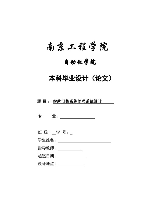
南京工程学院自动化学院本科毕业设计(论文)题目:指纹门禁系统管理系统设计专业:班级:学号:学生姓名:指导教师:起迄日期:设计地点:Graduation Design (Thesis)Fingerprint door system management system designBySupervised bySchool of AutomationNanjing Institute of TechnologyJuly, 2010摘要如今保险箱已经进入了各行各业,大量用于银行、宾馆、家庭等场合,而门锁是决定保险箱安全系数的最重要的因素。
随着科技的进步,指纹识别技术己经开始走入了我们的日常生活之中。
由于指纹具有唯一性和不变性,因此将指纹识别的应用,将大大提高安全性和可靠性。
指纹门禁系统硬件主要由指纹识别模块、微控器、液晶显示器、键盘、指纹识别模块的电源管理、存储器、日历/时钟芯片、电压检测、电控锁等部分组成。
软件主要由与指纹识别模块的通讯程序模块、指纹识别模块返回代码识别程序模块、开门模块程序模块、关门程序模块、显示程序模块、键盘识别程序模块、按I2C总线协议对时钟芯片和串行E2PROM的读/写程序模块等模块组成。
在本次指纹门禁系统管理系统的开发过程中,重点开发了门禁控制器中央模块及接口硬件设计,以及在AT89C52上对指纹模块SM-60的软件驱动子系统的开发工作,实现了相应的软硬件功能。
综上所述,论文开发了一套集多种功能于一体的门禁系统,可用于小区或楼宇的智能化工程。
该系统的开发为楼宇或小区的科学管理,以及建设适宜人居环境具有一定积极意义。
关键词:指纹门禁;单片机;I2C总线;AT89C52ABSTRACTNow safe already entered the professions, for Banks, hotels, families, etc and locks are safe safety coefficient of the most important factors. With the progress of science and technology, fingerprint identification technology has started to our daily life. Because, so will the fingerprint identification of application, will greatly improve the safety and reliability.Fingerprint door system hardware consists mainly of fingerprint module, micro control device, LCD monitor and keyboard, fingerprint module power management, memory, and calendar/clock chip, voltage detection, electronic lock components. Software with fingerprint module mainly by the communication program modules, fingerprint module return code identification procedures module, open and close program modules module, display module program modules, keyboard keys number identification procedures, according to the module of I2C bus protocols and serial E2PROM chips clock the read/write program module modules.In the fingerprint door system management system in the development process, the key development the central door controller interface module and hardware design, as well as on fingerprint module in AT89C52 SM - 60 software development work driving subsystem, the corresponding software and hardware function.To sum up, this paper developed a set of functions in one of the entrance guard system, can be used for residential building intelligence engineering or. This system development for building or residential construction of scientific management, and suitable for living environment has certain positive significance.Keywords: fingerprint door; microcontroller; AT89C52; I2C bus目录第一章绪论 (1)1.1引言 (1)1.2研究背景及意义 (1)1.3本文的结构 (2)第二章系统硬件设计 (3)2.1系统的硬件结构 (3)2.1.1 系统硬件设计综述 (3)2.1.2 硬件系统元器件概述 (4)2.2主控芯片硬件设计 (5)2.2.1 AT89C52介绍 (5)2.2.2 主要功能特性 (5)2.2.3 管脚说明 (6)2.2.4 主控芯片模块设计 (8)2.3指纹识别模块的硬件设计 (9)2.3.1 指纹识别模块 (9)2.3.2 电平信号转换 (10)2.3.3 稳压器 (11)2.3.4 数据接收设置 (12)2.4LCD液晶显示器模块硬件设计 (13)2.4.1 LCD模块 (13)2.4.2 接口电路设计 (14)2.5时钟/日历芯片模块硬件设计 (15)2.5.1 时钟/日历芯片元器件 (15)2.5.2 接口电路设计 (16)2.6E2PROM的读写程序模块硬件设计 (17)2.6.1 元器件参数 (17)2.6.2 元器件工作分配 (18)2.6.3 接口电路设计 (19)2.7键盘输入模块的硬件设计 (20)2.8电机正反转电路设计 (21)2.9紧急复位电路设计 (22)第三章系统软件设计 (24)3.1系统软件结构 (24)3.1.1 系统功能 (24)3.1.2 系统职能模块 (24)3.1.3 系统软件流程 (25)3.2显示程序软件设计 (26)3.2.1 显示器的读写时序及初始化 (26)3.2.2 显示程序设计 (27)3.3键盘输入模块软件设计 (29)3.4串行E2PROM的读/写程序模块软件设计 (31)3.4.1 I2C总线协议 (31)3.4.2 I2C总线写入程序 (31)3.4.3 I2C总线读程序 (32)3.5时钟/日历模块软件设计 (35)总结 (39)结论 (39)感悟 (39)致谢 (40)参考文献 (41)附录A: 系统硬件图 (42)附录B: 系统程序 (44)附录C: 系统调试图 (51)附件毕业论文光盘资料第一章绪论1.1 引言智能门禁系统是一种新型现代化安全管理系统,集自动识别技术和现代安全管理措施为主体,涉及电子、机械、光学、计算机技术、通讯技术、生物技术等诸多新技术。

Camera Card ConnectorsWiGig ModuleSensor ExpansionHDMIPower SwitchType C USBAudio CardConnectorsVolumeAMOLED 5.5" display with T ouch PanelJTAGAPQ8098 ProcessorCard NFC ExpansionSolution HighlightsMaterials are subject to change without notice.87-PD100-1 Rev BComprehensive and expandable development and evaluation kit for the Snapdragon 835 Mobile Platform.The Snapdragon 835 Mobile Hardware Development Kit provides an open-frame solution for technology companies tointegrate and innovate devices based on the Snapdragon 835 Mobile Platform.The Snapdragon 835 Mobile Hardware Development Kit is a feature-rich Android development platform that is designed to provide an ideal starting point for creating high-performance mobile devices and applications based on the Snapdragon 835 Mobile Platform. The kit includes the hardware, software tools and accessories needed to immediately begin your mobile development work.With an advanced 10-nanometer design, the Snapdragon 835 Mobile Platform can support phenomenal mobile performance. It is 35% smaller and uses 25% less power than its predecessor and is engineered to support exceptionally long battery life, lifelike VR and AR experiences, cutting-edge camera capabilities and Gigabit Class download speeds.The Snapdragon 835 mobile development platform is designed to provide original equipment manufacturers (OEMs),hardware/software vendors, developers and engineers with next generationsoftware technology and tools to accelerate development and testing of devices.Kit ContentsProcessor Card wtih APQ8098 Mini-ITX carrier board GNSS card12V AC power adapter Battery (optional) Charger USB cableSetup guideDisplay Adapter Card is an additional accessoryDevelopment PlatformQualcomm Snapdragon and APQ8098 are products of Qualcomm T echnologies, Inc. and/or its subsidiaries.Snapdragon 835 Processor CardThe Snapdragon 835 Processor Card measuring 60mm x 70mm is where all the processing occurs. It is connected to the carrier via two 240-pin high speed board-to-board connectors. A top side heat sink and a bottom side heat conductive metal plate provide thermal protection.The Processor Card provides the basic common set of features with minimal integration effort. It integrates the following: Snapdragon 835 (APQ8098) mainapplication processorLPDDR4X up to 1866MHz 4GB RAM (POP) PMi8998 + PM8998 – PMIC forPeripheral LDOs, Boost RegulatorsWCN3990 Wi-Fi+ BT+ FM combo chipover SLIMbus, Analog IQ, UART, PCM128 GB UFS 2.1WCD9341 Audio Code Dimensions170mm x 170mm Mini-ITX CPU Quad-core Qualcomm® Kryo™ 280 CPU64-bit ARMv8-compliant processor at up to 2.2GHz GPU Qualcomm® Adreno™ 540 GPUOpenGL ES 3.2, OpenCL 2.0 Full, Vulkan, DX12 DSP Qualcomm® Hexagon™ 682 DSP Memory and Storage4GB LPDDR4X PoP memory128GB UFS 2.1 Connectivity Wi-Fi: 802.11a/b/g/n/ac 2.4/5GHzBluetooth 5.0 + HS (backward compatible)GNSS (GPS/GLONASS/COMPASS/GALILEO) Camera Support3x MIPI CSI with support for 3D camera configuration Display2x MIPI dual 4-lane DSI + touch panel Multimedia HDMI 2.0 output - supports up to 4K UHD(3840 x 2400 at 60fps)and HDMI 2.0a (4K60)/ 4K30 Miracast I/O Interfaces1x PCIe, 1x JTAG, HDMI 2.0, 1x USB 3.1 Type C,1x USB 2.0 micro-B, 3x MIPI-CSI, 2x MIPI dual 4-lane DSI 4x Expansion headers for additional features (NFC, sensors etc.) LED3x General purpose LED, PMIC driven Battery 4.35V/3000mAh Operating System Android 7 Optional Accessories Display: 5.5” AMOLED LED (1440 x 2560)with PCAP Touch PanelCameras: 8M FF, Single 12M 2PD, Dual 12M+13M OZ+OIS SpecificationsWCN3990, WCD9341, PMi8998, PM8998, Qualcomm Hexagon, Qualcomm Adreno and Qualcomm Kryo are products of Qualcomm T echnologies, Inc. and/or its subsidiaries.©2018 Qualcomm T echnologies, Inc. All Rights Reserved. Qualcomm, Snapdragon, Hexagon, Kryo and Adreno are trademarks of Qualcomm Incorporated, registered in the United States and other countries. Other products and brand names may be trademarks or registered trademarks of their respective owners. 0318AT o learn more visit:。
![AT070TNA2 V[1].1 Pre(V01)_0830高清屏](https://img.taocdn.com/s1/m/3dcbc877f46527d3240ce02f.png)
CHIMEI INNO L U X DISPLAY CORPORATIONLCD MODULESPECIFICATIONCustomer:Model Name: AT070TNA2 V.1SPEC NO.: A070-A2-TT-11Date: 2010/08/30Version: 01■Preliminary Specification□Final SpecificationFor Customer’s AcceptanceApproved by CommentApproved by Reviewed by Prepared byHans Chen2010/08/30James YuCharlie Chou2010/08/30David Lee2010/08/30CHIMEI InnoLux copyright2004All rights reserved,Copying forbidden. Record of RevisionVersion ReviseDatePage ContentPre-Spec.01 2010/08/30 Initial Release.CHIMEI INNO L U XContents1. General Specifications (1)2. Pin Assignment (2)3. Operation Specifications (5)3.1. Absolute Maximum Ratings (5)3.1.1. Typical Operation Conditions (6)3.1.2. Current Consumption (7)3.1.3. Backlight Driving Conditions (7)3.2. Power Sequence (8)3.3. Timing Characteristics (9)3.3.1. AC Electrical Characteristics (9)3.3.2. Input Clock and Data Timing Diagram (9)3.3.3. DC Electrical Characteristics (10)3.3.4. Timing (11)3.3.5. Data Input Format (12)4. Optical Specifications (13)5. Reliability Test Items (17)6. General Precautions (18)6.1. Safety (18)6.2. Handling (18)6.3. Static Electricity (18)6.4. Storage (18)6.5. Cleaning (18)7. Mechanical Drawing (19)8. Package Drawing (20)8.1. Packaging Material Table (20)8.2. Packaging Quantity (20)8.3. Packaging Drawing (21)1. General SpecificationsNo. Item Specification Remark1 LCD size 7.0 inch(Diagonal)2 Driver element a-Si TFT active matrix3 Resolution 1024 × 3(RGB) × 6004 Display mode Normally White, Transmissive5 Dot pitch 0.05(W) × 0.15(H) mm6 Active area 153.6(W) × 90.0(H) mm7 Module size 165.75 (W) ×105.39(H) ×3.4(D) mm Note 18 Surface treatment Anti-Glare9 Color arrangement RGB-stripe10 Interface Digital11 View direction(Gray Inversion) 6 O’Clock12 Backlight power consumption 1.2W (Typ.)13 Panel power consumption 0.45W (Typ.)14 Weight TBD (Typ.)Note 1: Refer to Mechanical Drawing.2. Pin AssignmentFPC Connector is used for the module electronics interface. The recommended model is 20455-040E-02 manufactured by I-PEX.Pin No. Symbol I/O Function Remark1 VCOM P Common Voltage2 VDD P Power Voltage for digital circuit3 VDD P Power Voltage for digital circuit4 NC --- No connection5 Reset I Global reset pin6 STBYB I Standby mode, Normally pulled high STBYB = “1”, normal operation STBYB = “0”, timing controller, source driver will turn off, all output are High-Z7 GND P Ground8 RXIN0- I - LVDS differential data input9 RXIN0+ I + LVDS differential data input10 GND P Ground11 RXIN1- I - LVDS differential data input12 RXIN1+ I + LVDS differential data input13 GND P Ground14 RXIN2- I - LVDS differential data input15 RXIN2+ I + LVDS differential data input16 GND P Ground17 RXCLKIN- I - LVDS differential clock input18 RXCLKIN+ I + LVDS differential clock input19 GND P Ground20 RXIN3- I - LVDS differential data input21 RXIN3+ I + LVDS differential data input22 GND P Ground23 NC --- No connection24 NC --- No connection25 GND P Ground26 NC --- No connection27 DIMO O Backlight CABC controller signal output28 SELB I 6bit/8bit mode select Note129 AVDD P Power for Analog Circuit30 GND P Ground31 LED- P LED Cathode32 LED- P LED Cathode33 L/R I Horizontal inversion Note334 U/D I Vertical inversion Note335 VGL P Gate OFF Voltage36 CABCEN1 I CABC H/W enable Note237 CABCEN0 I CABC H/W enable Note238 VGH P Gate ON Voltage39 LED+ P LED Anode40 LED+ P LED AnodeI: input, O: output, P: PowerNote1: If LVDS input data is 6 bits ,SELB must be set to High;If LVDS input data is 8 bits ,SELB must be set to Low.Note2: When CABC_EN=”00”, CABC OFF.When CABC_EN=”01”, user interface image.When CABC_EN=”10”, still picture.When CABC_EN=”11”, moving image.When CABC off, don’t connect DIMO, else connect it to backlight. Note3: When L/R=”0”, set right to left scan dirction.When L/R=”1”, set left to right scan dirction.When U/D=”0”, set top to bottom scan dirction.When U/D=”1”, set bottom to top scan dirction.Note: Definition of scanning direction.Refer to the figure as below:3. Operation Specifications3.1. Absolute Maximum Ratings(Note 1)ValuesUnit Remark Item SymbolMin. Max.DV DD -0.3 5.0 VAV DD 6.5 13.5 V Power voltageV GH -0.3 42.0 VV GL -20.0 0.3 VV GH-V GL- 40.0 V Operation Temperature T OP -20 60 ℃Storage Temperature T ST-30 70 ℃LED Reverse Voltage V R- 5 VEach LED LED Forward Current I F- 35 mA Each LEDNote 1: The absolute maximum rating values of this product are not allowed to be exceeded at any times. Should a module be used with any of the absolute maximum ratingsexceeded, the characteristics of the module may not be recovered, or in an extremecase, the module may be permanently destroyed.3.1.1. Typical Operation Conditions( Note 1)ValuesUnit Remark Item SymbolMin. Typ. Max.DV DD 3.0 3.3 3.6 V Note 2AV DD 10.8 11 11.2 VPower voltageV GH 19.7 20 20.3 VV GL -6.5 -6.8 -7.1 VInput signal voltage V COM 3.6 3.8 4.0 VInput logic high voltage V IH 0.7 DV DD - DV DD VNote 3 Input logic low voltage V IL 0 - 0.3 DV DD VNote 1: Be sure to apply DV DD and V GL to the LCD first, and then apply V GH.Note 2: DV DD setting should match the signals output voltage (refer to Note 3) of customer’s system board.Note 3: LVDS,Reset.3.1.2. Current ConsumptionValuesItem SymbolMin. Typ. Max.Unit RemarkI GH - 0.2 1.0 mA V GH =20VI GL - 0.2 1.0 mA V GL = -6.8V IDV DD - 50 60 mA DV DD =3.3VCurrent for DriverIAV DD - 25 30 mA AV DD =11V3.1.3. Backlight Driving ConditionsValuesItem SymbolMin. Typ. Max.Unit Remark Voltage for LED backlight V L -- 9.3 10.2 V Note 1 Current for LED backlight I L -- 120 130 mALED life time - - 20,000 - Hr Note 2Note 1: The LED Supply Voltage is defined by the number of LED at Ta=25℃ andI L =120mA.Note 2: The “LED life time” is defined as the module brightness decrease to 50% original brightness at Ta=25℃ and I L =120mA. The LED lifetime could be decreased ifoperating I L is lager than 120mA.3.2. Power Sequencea. Power on:T=0 GNDVGLDATASTBYB VDD A VDDBLU VGH >20ms>20ms>10ms>10ms>20msTT=0>20msT>5ms>50ms>50ms>10ms>=0msVGH A VDD VDD STBYB RESETVGLB/LDATA3.3. Timing Characteristics3.3.1. AC Electrical CharacteristicsValuesParameter SymbolUnit RemarkMin. Typ. Max.Clock frequency R xFCLK40.8 51.2 71 MHzInput data skew margin T RSKM500 - - psClock high time T LVCH- 4/(7* R xFCLK) - nsClock low time T LVCL- 3/(7* R xFCLK) - ns3.3.2. Input Clock and Data Timing Diagram3.3.3. DC Electrical CharacteristicsValuesParameter SymbolMin. Typ. Max.Unit RemarkDifferential input highThreshold voltageR xVTH- - +0.1 VDifferential input low Threshold voltage R xVTH-0.1 - - VR XVCM=1.2VInput voltage range(singled-end)R xVIN0 - 2.4 V Differential input common modevoltageR xVCM|V ID|/2 - 2.4-|V ID|/2 V Differential voltage|V ID|0.2 - 0.6 V Differential input leakage current RV xliz-10 - +10 uA3.3.4. TimingValuesItem SymbolMin. Typ. Max.Unit RemarkClock Frequency fclk 40.8 51.2 67.2 MHz Frame rate =60HzHorizontal display area thd1024 DCLK HS period time th1114 1344 1400 DCLK HS Blanking thb90 320 376 DCLK Vertical display area tvd600 H VS period time tv610 635 800 H VS Blanking thb10 35 200 H3.3.5. Data Input Format6bit LVDS input8bit LVDS inputNote: Support DE timing mode only, SYNC mode not supported.4. Optical SpecificationsValuesItemSymbolConditionMin.Typ. Max. UnitRemarkθLΦ=180°(9 o’clock) - 75 - θR Φ=0°(3 o’clock) - 75 -θT Φ=90°(12 o’clock) - 70 - Viewing angle (CR≥ 10)θB Φ=270°(6 o’clock)- 75 - degree Note 1 T ON-1020msecNote 3Response timeT OFF- 10 20 msec Note 3 Contrast ratioCR 500 700 - - Note 4 W X0.26 0.31 0.36 - Color chromaticityW Y0.28 0.33 0.38 - Note 2 Note 5 Note 6 LuminanceL200250-cd/m²Note 6LuminanceuniformityY U Normal θ=Φ=0°70 75 - % Note 7Test Conditions:1. DV DD =3.3V, I L =120mA (Backlight current), the ambient temperature is 25℃.2. The test systems refer to Note 2.Fig. 4-1 Definition of viewing angleNote 2: Definition of optical measurement system.The optical characteristics should be measured in dark room. After 30 minutesoperation, the optical properties are measured at the center point of the LCD screen. (Response time is measured by Photo detector TOPCON BM-7, other items are measured by BM-5A/Field of view: 1° /Height: 500mm.)Fig. 4-2 Optical measurement system setupNormal line θ=Φ=0°Photo detectorΦ=90°12 o’clock directionΦ=270°6 o’clock directionΦ=0°Φ=180°Active Area500mmLCMθ=Φ=0°Φ=90°12 o’clock direction Φ=270°6 o’clock direction Φ=0°Φ=180°Active AreaθLθTθBθRLCMNote 3: Definition of Response timeThe response time is defined as the LCD optical switching time interval between“White” state and “Black” state. Rise time (T ON ) is the time between photo detector output intensity changed from 90% to 10%. And fall time (T OFF ) is the time between photo detector output intensity changed from 10% to 90%.Fig. 4-3 Definition of response timeNote 4: Definition of contrast ratiostate Black"" the on LCD when measured Luminance state White"" the on LCD when measured Luminance (CR) ratio Contrast =Note 5: Definition of color chromaticity (CIE1931)Color coordinates measured at center point of LCD.Note 6: All input terminals LCD panel must be ground while measuring the center area ofthe panel. The LED driving condition is I L =120mA .90%10% 0%P h o t o d e t e c t o r o u t p u t (R e l a t i v e v a l u e )ONT White (TFT OFF)Black (TFT ON)White (TFT OFF)Note 7: Definition of Luminance UniformityActive area is divided into 9 measuring areas (Refer to Fig. 4-4 ).Every measuring point is placed at the center of each measuring area.max minB B (Yu)Uniformity Luminance =L-------Active area length W----- Active area widthWW /3W /3W /6L/3L/3L/6LFig. 4-4 Definition of measuring pointsB max : The measured maximum luminance of all measurement position. B min : The measured minimum luminance of all measurement position.5. Reliability Test Items(Note3)Item Test Conditions Remark High Temperature Storage Ta = 70℃240hrs Note 1,Note 4 Low Temperature Storage Ta = -30℃240hrs Note 1,Note 4 High Temperature Operation Ts = 60℃240hrs Note 2,Note 4 Low Temperature Operation Ta = -20℃240hrs Note 1,Note 4 Operate at High Temperatureand Humidity+40℃, 90%RH 240hrs Note 4Thermal Shock -30℃/30 min ~ +70℃/30 min for a total 100cycles, Start with cold temperature and endwith high temperature.Note 4Vibration Test Frequency range:10~55Hz Stroke:1.5mmSweep:10Hz~55Hz~10Hz2 hours for each direction of X. Y. Z.(6 hours for total)Mechanical Shock 100G 6ms,±X, ±Y, ±Z 3 times for each directionPackage Vibration Test Random Vibration :0.015G*G/Hz from 5-200HZ, -6dB/Octave from 200-500HZ2 hours for each direction of X. Y. Z.(6 hours for total)Package Drop Test Height:60 cm1 corner, 3 edges, 6 surfacesElectro Static Discharge ± 2KV, Human Body Mode, 100pF/1500ΩNote 1: Ta is the ambient temperature of samples.Note 2: Ts is the temperature of panel’s surface.Note 3: In the standard condition, there shall be no practical problem that may affect the display function. After the reliability test, the product only guarantees operation,but don’t guarantee all of the cosmetic specification.Note 4: Before cosmetic and function test, the product must have enough recovery time, at least 2 hours at room temperature.6. General Precautions6.1. SafetyLiquid crystal is poisonous. Do not put it in your mouth. If liquid crystal touches your skin or clothes, wash it off immediately by using soap and water.6.2. Handling1. The LCD panel is plate glass. Do not subject the panel to mechanical shock or toexcessive force on its surface.2. The polarizer attached to the display is easily damaged. Please handle it carefullyto avoid scratch or other damages.3. To avoid contamination on the display surface, do not touch the module surfacewith bare hands.4. Keep a space so that the LCD panels do not touch other components.5. Put cover board such as acrylic board on the surface of LCD panel to protect panelfrom damages.6. Transparent electrodes may be disconnected if you use the LCD panel underenvironmental conditions where the condensation of dew occurs.7. Do not leave module in direct sunlight to avoid malfunction of the ICs.6.3. Static Electricity1. Be sure to ground module before turning on power or operating module.2. Do not apply voltage which exceeds the absolute maximum rating value.6.4. Storage1. Store the module in a dark room where must keep at 25±10℃ and 65%RH or less.2. Do not store the module in surroundings containing organic solvent or corrosivegas.3. Store the module in an anti-electrostatic container or bag.6.5. Cleaning1. Do not wipe the polarizer with dry cloth. It might cause scratch.2. Only use a soft sloth with IPA to wipe the polarizer, other chemicals mightpermanent damage to the polarizer.7. Mechanical Drawing8. Package Drawing8.1. Packaging Material TableNo. ItemModel(Material)Dimensions(mm)UnitWeight(kg)Quantity Remark1 LCMModuleAT070TNA2 V.1 165.75 × 105.39 × 3.4 TBD 502 Partition BC Corrugatedpaper512 × 349 × 226 1.466 1set3 CorrugatedPaperB Corrugatedpaper510 × 350 0.071 4pcs4 CorrugatedBarB Corrugatedpaper512 × 11 × 3 0.046 4pcs5 Dust-ProofBagPE 700 × 530 0.048 1pcs6 A/S Bag PE 180 × 133 × 0.2 0.002 50pcs7 Carton Corrugatedpaper530 × 355 × 255 1.100 1pcs8 Total weight TBD8.2. Packaging QuantityTotal LCM quantity in Carton: no. of Partition 2 Rows × quantity per Row 25 = 508.3. Packaging Drawing。

CAMERA COMPONENT DESCRIPTIONSSPECIFICATIONS* All specifications subject to change without notice for quality improvementIn-Line Cable Mounted OSD ControlMounting Base Locking CollarFocusAdjustmentZoomAdjustmentAVAILABLE ACCESSORIESPACKAGE CONTENTS(1) Camera(1) Mounting Hardware Packet (1) User ManualOSD CONTROLPress the Joystick button on the cable mounted OSD control to access the OSD menu.DWMVFBB Gray Back Box DWMVFBBW White Back BoxLensMANUAL USER 1 / USER2BACKLIGHT D-WDRON / OFFAutoMODE = AUTO, CENTER LEVEL = 0~31CAMERA ID ON/OFFSYNC LANGUAGEON = 50 Characters Maximum, Position Selectable ENGLISH, CHINESE, JAPANESE, SPANISH PORTUGUESE, RUSSIAN, FRENCH, GERMANINTCAMERA RESET / BACK / EXIT / SAVE ALLOSD MenuDAY/NIGHTNR MODE2-DNR YC = Y LEVEL, C LEVEL 0~15 AdustableC = C LEVEL 0~15 AdustableY = Y LEVEL, 0~15 AdustableOFFBURST = ON/OFF, DELAY COUNT = 0~255, DAY->NIGHT = 0~255,NIGHT->DAY = 0~255BURST = ON/OFFIR OPTIMIZER = ON / OFFB/WEXT1 / EXT2COLORAREA SELECT 1/4, 2/4, 3/4, 4/4, TOP, BOTTOM, LEFT, RIGHT AdustableOFFAREA SELECT 1/8 ~ 8/8 , TOP, BOTTOM, LEFT, RIGHT AdustableCOLOR = 1~8 SelectableTRANSP = 0.25, 0.50, 0.75, 1.00MOSAIC ON/OFFON - 8 ZONEMONITOR AREA = ON/OFFLevel 24~90 AdustableB-GAIN / R-GAIN LEVEL 0~255 AdjustableANTI CR PUSH PUSH LOCK OFF / BLC / HLC HUE = 0~255 Adjustable GAIN = 0~255 AdjustableON = Luminance = MID - LOW - HIGHCONTRAST = LOW - MID - MIDLOW - MIDHIGH - HIGH OFFDETECT SENSE = 0~127BLOCK DISP = OFF / ON ON = 16X24 Grid AdjustablePRIVACYManualHigh Luminance Mode SHUT / Brightness 0~255 AdjustableLow Luminance Mode AGC / OFF - Brightness x0.25 ~ x 1.00 AdjustableMode = SHUT+AGCSHUTTER = 1/60, 1/120, 1/250, 1/500, 1/1000, 1/2000, 1/4000, 1/10000AGC = 6, 12, 18, 24, 30, 36, 42, 44.8SPEED = 0~255 / DELAY CNT = 0~255 / ATW FRAME = x0.50. x1.00, x1.50, x2.00ENVIRONMENT = INDOOR/ OUTDOORPICTURE ADJUSTMOTION DETON - 4 ZONEMIRROR = ON/OFFBRIGHTNESS = 0~255 Adjustable CONTRAST = 0~255 Adjustable SHARPNESS = 0~255 AdjustableAutoManual SHUTTER / AGCATWWHITE BALANCEOSD MENU TREE。

用户手册DLP 投影仪使用产品前请阅读使用说明。
保留备用。
BU50NST-GLBU60PST-GLP/NO : SAC37813570 (2102-REV02)版权 © 2020 乐金电子(中国)有限公司版权所有。
2中文目录许可证 3开源软件提示信息 4安全预防措施 5准备工作 17安装 25遥控器 34连接设备 37规格 43标志 49故障排除 503中文许可证不同型号所支持的许可证可能会有所不同。
有关许可证的详细信息,请访问 。
HDMI、HDMI高清晰度多媒体接口以及HDMI标志是HDMI Licensing Administrator, Inc.在美国和其他国家的商标或注册商标。
本产品经过杜比实验室的许可而制造。
杜比, 杜比视界,杜比音效,杜比全景声,和双 D 符号是杜比实验室的注册商标。
有关 DTS 专利,请参阅 。
在获得 DTS Licensing Limited 许可的条件下制造。
DTS、符号、DTS 与符号同时出现、DTS 2.0 Channel、DTS 2.0+Digital Out、DTS-HD 和 DTS Virtual:X 是 DTS, Inc. 在美国和/或其他国家/地区的注册商标或商标。
© DTS, Inc. 保留所有权利。
注意• 所示的图像可能与您的投影仪有所不同。
• 投影仪的 OSD(在屏显示)可能与此手册的显示略有不同。
4中文开源软件提示信息为取得本产品内搭载的 GPL、LGPL、MPL 及其他开源证书下的源代码,请您访问 。
除源代码以外,所有相关的许可条款、免责声明和版权通知均可供下载。
LG Electronics 也可以 CD-ROM 的形式为您提供开源代码,如有需要,请发送电子邮件至******************,仅收取执行配送的费用(如介质费用、运输费和手续费)。
此报价从该产品出厂之日起,三年内有效。
此报价对收到本信息的任何人有效。
w w w.d a t a v i d e o.c o m7" TFT LCD MONITOR2Standard Warranty• Datavideo equipment is guaranteed against any manufacturing defects for one year from the date of purchase.• The original purchase invoice or other documentary evidence should be supplied at the time of any request for repair under warranty.• Damage caused by accident, misuse, unauthorized repairs, sand, grit or water is not covered by this warranty.• All mail or transportation costs including insurance are at the expense of the owner.• All other claims of any nature are not covered.• Cables & batteries are not covered under warranty.• Warranty only valid within the country or region of purchase.• Your statutory rights are not affected.Two Year Warranty• All Datavideo products purchased after 01-Oct.-2008 qualify for a free one year extension to the standard Warranty, providing the product is registered with Datavideo within 30 days of purchase. For information on how to register please visit or contact your local Datavideo office or authorized Distributors• Certain parts with limited lifetime expectancy such as LCD Panels, DVD Drives, Hard Drives are only covered for the first 10,000 hours, or 1 year (whichever comes first).• Any second year warranty claims must be made to your local Datavideo office or one of its authorized Distributors before the extended warranty expires.WarrantyWelcome to the TLM-700HD Instruction ManualThank you for choosing a Datavideo product, pleasevisit the support pages on our website for the latestversion of the instruction manual./LCD+Monitors/TLM-700HDDon’t forget to register your product online to qualify foran additional free one year extension to the standardwarranty, and to receive information from Datavideo onservice & information relevant to your Datavideo productincluding new software updates & driversTLM-700HD3Disclaimer of Product and Services The information offered in this instruction manual is intended as a guide only. At all times, Datavideo Technologies will try to give correct, complete and suitable information. However, Datavideo Technologies cannot exclude that some information in this manual, from time to time, may not be correct or may be incomplete. This manual may contain typing errors, omissions or incorrect information. Datavideo Technologies always recommend that you double check the information in this document for accuracy before making any purchase decision or using the product. Datavideo Technologies is not responsible for any omissions or errors, or for any subsequent loss or damage caused by using the information contained within this manual. Further advice on the content of this manual or on the product can be obtained by contacting your local Datavideo Office or dealer. ContentsWelcome to the TLM-700HD Instruction Manual 2Warranty 2Standard Warranty 2Two Year Warranty 2Disposal 4Warnings and Precautions 4Packing List 5Introduction 5Features 6Supported Formats 6Connections & Controls 7Front Panel 7Rear Panel 9Menu Options 101. Picture (Screen Setup) 10Picture setting 10Brightness 102. Audio (Audio Indicator) 103. Function (Center Mark, Safety Zone) 10Center Mark 10Safety Zone 104. Setup (On Screen Display, Time Code) 11OSD Timer 11OSD Blending 11Time Code 11TC Position 11TC HD Line 11TC SD Line 11TC Font Size 115. Advance (LCD Display, Reset Firmware Version) 12LCD L/R Scan 12LCD U/D Scan 12Reset 12Calibrating Datavideo Monitors 12Tally light indication 13TLM-700HD Model & Battery Plate Variations 14Specifications 15Service & Support 167" TFT LCD MONITOR4Warnings and Precautions1.Read all of these warnings and save them for later reference.2.Follow all warnings and instructions marked on this unit.3.Unplug this unit from the wall outlet before cleaning. Do not use liquid or aerosol cleaners. Use a slightly damp cloth for cleaning.4.Do not use this unit in or near water.5.Do not place this unit on an unstable surface, cart, stand, or table. The unit may fall, causing serious damage.6.Any slots and openings on the case top, back, and bottom are provided for ventilation. To ensure safe and reliable operation of this unit, and to protect it from overheating, do not block or cover these openings. Do not place this unit on a bed, sofa, rug, or similar surface, as the ventilation openings may become blocked. This unit should never be placed near or over a heat source or radiator. This unit should not be placed in a built-in installation unless proper ventilation is provided.7.This product should only be operated from the type of power source indicated on the marking label of the AC adapter. If you are not sure of the type of power available, consult your Datavideo dealer or your local power company.8.Do not allow anything to rest on the power cord. Do not locate this unit where the power cord will be walked on, rolled over, damaged or otherwise stressed.9.If an extension cord must be used with this unit, make sure that the total of the ampere ratings on the products plugged into the extension cord do not exceed the extension cord’s rating.10.Make sure that the total amperes of all the units that are plugged into asingle wall outlet do not exceed 15 amperes.11.Never push objects of any kind into this unit through the case ventilationslots, as they may touch dangerous voltage points or short out parts that could result in risk of fire or electric shock. Never spill liquid of any kind onto or into this unit.12.Except as specifically explained elsewhere in this manual, do not attemptFor EU Customers only - WEEE MarkingThis symbol on the product indicates that it will not be treatedas household waste. It must be handed over to the applicabletake back scheme for the recycling of electrical and electronicequipment. For more detailed information about the recycling ofthis product, please contact your local Datavideo office.DisposalTLM-700HD5Introductionto service this product yourself. Opening or removing covers that are marked “Do Not Remove” may expose you to dangerous voltage points or other risks, and will void your warranty. Refer all service issues to qualified service personnel.13.Unplug this product from the wall outlet and refer to qualified service personnel under the following conditions:a.When the power cord is damaged or frayed;b.When liquid has spilled into the unit;c.When the product has been exposed to rain or water;d.When the product does not operate normally under normal operating conditions. Adjust only those controls that are covered by the operating instructions in this manual; improper adjustment of other controls may result in damage to the unit and may often require extensive work by a qualified technician to restore the unit to normal operation;e.When the product has been dropped or the case has been damaged;f. When the product exhibits a distinct change in performance, indicating a need for service.The Datavideo TLM-700HD is a 7 Inch monitor designed for use in the field or in a studio. The TLM-700HD can be powered from a standard V-Mount battery connection or by mains power. It is rugged and easy to carry with a variety of professional features and connections that make it easy for set up and intuitive to use.7" TFT LCD MONITOR6FeaturesSupported Formats• 7" 16:9 Wide Screen Panel• Resolution: 800 x 480 dots• View Angle (V)+60/-40°, (H)+60/-60°• HD/SD-SDI, YUV, HD-YUV, HDMI & CV Input• Internal colour bar• Blue only function• Audio indicator for SDI, HDMI• Safe Area indicator• VITC time code display• Dual colour tally light indicator• Brightness, Contrast, Colour, Tint Adjustable• Colour T emp* adjustable• Audio Level indicators• NTSC / PAL Auto Switching• 4:3 / 15:9 / 16:9 switchable* can be set to 9300, 7500, 6500, 5400 or USER RGB values.■ HDMI YUV• 720 x 576i x 50 Hz• 720 x 480i x 60 Hz• 1280 x 720p x 50 Hz• 1280 x 720p x 60 Hz• 1920 x 1080i x 50 Hz• 1920 x 1080i x 60 Hz■ HDMI RGB• 720 x 576i x 50 Hz• 720 x 480i x 60 Hz• 1280 x 720p x 50 Hz• 1280 x 720p x 60 Hz• 1920 x 1080i x 50 Hz• 1920 x 1080i x 60 Hz■ SDI• 720 x 576i / 50 Hz• 720 x 480i / 60 Hz• 1280 x 720p / 60 Hz• 1280 x 720p / 50 Hz• 1920 x 1080i / 50 Hz• 1920 x 1080i / 60 Hz■ YUV• 720 x 576i x 50 Hz• 720 x 480i x 60 Hz• 1280 x 720p x 50 Hz• 1280 x 720p x 60 Hz• 1920 x 1080i x 50 Hz• 1920 x 1080i x 60 Hz■ CV• 720 x 576i (PAL)• 720 x 480i (NTSC)TLM-700HD7Front Panel Connections & ControlsPOWERON OFFSOURCEASPECT Power Switch Switches the power On / Off.Stereo Headphone Mini Jack socket The level is adjusted by headphone volume control.Listen to embedded audio from HDMI or SDI sources.Source Button Selects Input include SDI, YPbPr, CVBS, and HDMI.Aspect Ratio Button Select 4.3, 15:9, or 16:9PATTERN Generate on colour bars.7" TFT LCD MONITOR8BLUEFor blue only display to allow accurate chromaand phase adjustments with NTSC signals.MENUCalls up the on-screen adjustment menu (SeePage10 Menu Options for more details).UP / DOWNMenu navigation controls.ENTERConfirms the new settings or return to the defaultstate.TALLY LIGHTRed = LiveAmber = StandbyMENUENTERTLM-700HD9BNC connector for Analogue (Composite) videoinput.HDMI in interface Supports HDMI 1.1Tally In Sends in red and amber colour tally signal to tally LED. Red means on-air, amber means standby.DC in socket Connects the supplied 12V 1A PSU to this socket. The connection can be secured by screwing the outer fastening ring of the DC In plug to the socket.7" TFT LCD MONITOR10Menu Options1. Picture (Screen Setup)Picture setting■ Press the MENU button once to display the Picture setting menu.■ Press the ENTER button to highlight the Brightness setting.■ Press the UP or DOWN button to highlight the setting that needs to be adjusted.Brightness■ Press ENTER button to select the Brightness setting.■ Press the UP or DOWN button to adjust the Brightness value between 0 and 100.■ Press ENTER button again to save and return to the Picture setting menu;now highlight another Picture setting to be adjusted. To select a different setting (Contrast, Saturation, Tint, Color Temp*) use the UP / DOWN buttons. Follow the same procedure to set the other values.■ Keep pressing the MENU button to cycle through the main menu options.■ Press the SOURCE button to exit the menu mode.* N.B.: Color Temp can be set to 9300, 7500, 6500, 5400 or USER RGB values.2. Audio (Audio Indicator)■ Press the MENU button twice to display the Audio setting menu.■ Press the ENTER button to highlight the Indicator setting.■ Press the ENTER button again to toggle the on screen audio indicator ON/OFF.■ Keep pressing the MENU button to cycle through the main menu options.■ Press the SOURCE button to exit the menu mode.3. Function (Center Mark, Safety Zone)■ Press the MENU button three times to display the Function. Settings menu.Center Mark■ Press the ENTER button to highlight the Center Mark setting.■ Press the ENTER button to toggle the on screen Center Mark ON/OFF. Safety Zone■ Press the UP or DOWN button to highlight the Safety Zone setting.■ Keep pressing the ENTER button to cycle through the values 80%, 90% or OFF.■ Press the UP or DOWN button to exit the Safety Zone setting. To selecta different setting (4:3 Screen, Cinema Zone) use the UP or DOWNbuttons. Follow the same procedure to set the next setting.■ Keep pressing the MENU button to cycle through the main menu options.■ Press the SOURCE button to exit the menu mode.TLM-700HD114. Setup (On Screen Display, Time Code)■ Press the MENU button four times to display the Setup setting menu.OSD Timer■ Press the ENTER button to highlight the OSD Timer setting.* N.B.: OSD Timer sets how long the setting menus will stay on screen.■ Press the ENTER button again to display the OSD Timer setting position.■ Press the UP or DOWN button to set the OSD value between 5 to 60 SEC.■ Press ENTER button to save the OSD value.OSD Blending■ Press the UP or DOWN button to highlight the OSD Blending setting.* N.B.: OSD Blending sets how transparent the setting menus will be on screen.■ Press the ENTER button to display the OSD Blending setting position.■ Press the UP or DOWN button to select the OSD blending value (from 0~7).* N.B.: OSD Blending value 0 = Min transparency 7 = Max transparency ■ Press the ENTER button to save the OSD blending value. Time Code■ Press the UP or DOWN button to highlight the Time Code setting.■ Press the ENTER button to toggle the on screen Time Code display ON/OFF.TC Position■ Press the UP or DOWN button to highlight the TC Position setting.* N.B.: TC Position is used to set where on the monitor Time Code will be shown.■ Press the ENTER button to cycle through the possible Time Code Positions on the monitor (Left/Up, Middle/Down, Right/Down, Right/Up)TC HD Line■ Press the UP or DOWN button to highlight the TC HD Line setting.■ Press ENTER button to cycle through the possible HD time code lines (8~20).TC SD Line■ Press the UP or DOWN button to highlight the TC SD Line setting.■ Press ENTER button to cycle through the possible SD time code lines (10~21).TC Font Size■ Press the UP or DOWN button to highlight the TC Font Size setting.■ Press ENTER button to cycle through the possible time code font sizes on the screen (Large or Small).■ Keep pressing the MENU button to cycle through the main menu options.■ Press the SOURCE button to exit the menu mode.7" TFT LCD MONITOR12Calibrating Datavideo MonitorsCalibrating professional monitors is crucial.For guidance on how to calibrate a Datavideo Monitor using SMPTE colour bars please visit our website /specs/Datavideo_Calibrating_Monitors.pdf 5. Advance (LCD Display, Reset Firmware Version)■ Press the MENU button five times to display the Advance setting menu.LCD L/R Scan■ Press the ENTER button to highlight the LCD L/R Scan setting.* N.B.: The LCD L/R Scan will reverse the image displayed horizontally.■ Press the ENTER button, the screen image will be reversed (Left to Right).■ Press the ENTER button again, the screen image will return to normal view.LCD U/D Scan■ Press UP / DOWN button to highlight the LCD U/D Scan setting.* N.B.: The LCD U/D Scan will reverse the image displayed vertically.■ Press the ENTER button, the screen image will be reversed (Top to Bottom).■ Press the ENTER button again, the screen image will return to normal view.Reset■ Press UP / DOWN button to highlight the Reset option.* N.B.: This option will return the monitor to the factory default settings.■ Press the ENTER button to re-start the monitor with the factory default settings.Version■ Press UP / DOWN button to highlight the Version setting.■ Press the ENTER button, the firmware version will be displayed on screen.■ Keep pressing the MENU button to cycle through the main menu options.■ Press the SOURCE button to exit the menu mode.TLM-700HD13Tally light indicationThe TLM-700HD has a tally input connector on the rear panel; many digital video switchers can provide tally light signals to this connector. The Datavideo range of intercom systems can also be used to pass on thesetally signals.Tally InD-sub 15pin type connector.TALLY LIGHTRed = LiveAmber = Standby7" TFT LCD MONITOR14TLM-700HD Model & Battery Plate VariationsTLM-700HD:with V-mount Battery PlateTLM-700HD-C:with Canon battery mountTLM-700HD-P:with Panasonic battery mountTLM-700HD-S1 & -S2:with Sony battery mountTLM-700HD-A:with Anton Bauer battery mountThere are several versions ofTLM-700HD monitor with differentbattery connection plates.TLM-700HD Specifications15All the trademarks are the properties of their respective owners. Datavideo Technologies Co., Ltd. All rights reserved 2018Service & SupportJan-24.2014 P/N: G082060476E6It is our goal to make your products ownership a satisfying experience. Our supporting staff is available to assist you in setting up and operating your system. Please refer to our web site for answers to common questions, support requests or contact your local office below.R.O.C.U.S.A.Datavideo Technologies (S) PTE Ltd No. 178 Paya Lebar Road #06-03Singapore 409030Tel:+65-6749 6866Fax:+65-6749 3266E-mail:******************Datavideo United KingdomDatavideo SingaporeDatavideo UK LimitedUnits1 & 2 Waterside Business Park Hadfield, Glossop, Derbyshire SK13 1BE, UKTel:+44-1457 851 000Fax:+44-1457 850 964E-mail:******************.ukDatavideo IndiaDatavideo Technologies India Pvt Ltd Fax:+91-0120-2427338E-mail:******************Tel:+91-0120-2427337A-132, Sec-63,Noida-201307,Uttar Pradesh (UP), India.Datavideo Technologies Co. Ltd10F. No. 176, Jian 1st Rd.,Chung Ho District, New Taipei City 235, Taiwan, Tel: +886-2-8227-2888Fax: +886-2-8227-2777E-mail:*********************.twDatavideo Corporation 7048 Elmer Avenue.Whittier, CA 90602, Tel:+1-562-696 2324Fax:+1-562-698 6930E-mail:******************Datavideo USADatavideo TaiwanDatavideo Hong KongDatavideo Hong Kong Ltd G/F.,26 Cross Lane Wanchai, Hong Kong Tel: +852-2833-1981Fax: +852-2833-9916E-mail:******************.hkDatavideo Technologies Europe BV Floridadreef 1063565 AM Utrecht, The NetherlandsTel:+31-30-261-96-56Fax:+31-30-261-96-57E-mail:*****************Datavideo The NetherlandDatavideo ChinaDatavideo Technologies China Co101,NO.618,LiuYing Rd,Zhabei District,Shanghai,ChinaTel: +86 21-5603 6599Fax: +86 21-5603 6770E-mail:********************Datavideo FranceDatavideo France s.a.r.lCité Descartes 1,rue Albert Einstein Champs sur Marne774477-Marne la Vallée cedex 2Tel:+33-1-60370246E-mail:*****************。
1. OVERVIEW 1. OVERVIEW CLAA CLAA070WP03070WP03070WP03 is 7” color TFT-LCD (Thin Film Transistor Liquid Crystal Display) module composed of LCD panel, LVDS driver ICs, control circuit and backlight. By applying 6 bit digital data, 800×RGB (3) ×1280, 262,144-color images are displayed on the 7” diagonal screen. general specifications are summarized in the following table:ITEM ITEMSPECIFICATION SPECIFICATIONDisplay Area94.2(H)x150.72(V) (mm) (7-inch diagonal)Number of Pixels 800 ×3(H)×1280 (V) Pixel Pitch0.11775(H)×0.11775(V) (mm)Color Pixel Arrangement RGB vertical stripe Display Mode Normally Black Number of Colors 262,144(6bits)(LVDS)Gamut60%(Typ) Optimum Viewing Angle whole view Response Time 60ms (Max) Surface TreatmentHC , Hardness:3H Viewing Angle(CR>10) 85°、85° / 85°、85°(Min)Brightness 450 cd/m 2(5points, average) (Typ)Uniformity9point:80 %(Typ.)Consumption of Power 0.5 (LCD Module Typical)/ 1.692 (Backlight Typical)Module Size 161.67(H)×104.32(V)×3.85(D) (Typ.)Module Weight101g (Max)The LCD Products listed on this document are not suitable for use of aerospace equipment, submarine cable, and nuclear reactor control system and life support systems. If customers intend to use these LCD products for applications listed above or those not included in the "Standard" list as follows, please contact our sales in advance.Standard:Computer, Office equipment, Communication equipment, Test and Measurement equipment,Machine tool, Industrial robot, Audio and Visual equipment, Other consumer products.2. ABSOLUTE MAXIMUM RATINGS 2. ABSOLUTE MAXIMUM RATINGSThe following are maximum value, which if exceeded, may cause faulty operation or damage to the unit.ITEM ITEM SYMBOL SYMBOL MIN.MIN. MAX.MAX. UNIT UNIT NOTE NOTE LCD Power Voltage VDD 0 5 V Operation Temperature Top 0 50 ℃ *1). 2). 3). 4) Storage TemperatureTstg-2565℃*1). 2). 3)【Note】*1) The relative temperature and humidity range are as below sketch, 90%RH Max. (Ta≦40℃) *2) The maximum wet bulb temperature ≦39℃(Ta>40℃) and without dewing.*3) If product in environment which over the definition of the relative temperature and humidity outof range too long, it will affect visual of LCD.*4) If you operate LCD in normal temperature range, the center surface of panel should be under50℃.3. ELECTRICAL CHARACTERISTICS 3. ELECTRICAL CHARACTERISTICS (A) TFT LCD TFT LCDTEM SYMBOL SYMBOL MIN MIN TYP TYP MAX MAX UNIT UNIT NOTE NOTE LCD Power Voltage VDD 3 3.3 3.6 V*1) LCD Power Current IDD - - - mA *2) Rush CurrentIrush--2A*4)【Note】*1) Power Sequence:0.5 ms ≦t1≦10ms 500 ms≦t4 0.01 ms<t2≦50 ms 200 ms≦t5 0.01 ms<t3≦50 ms200 ms≦t6Vin-dip state(1)when 3.0V>Vin≧2.7V,td≦10 ms.(2)when Vin<2.7V,Vin-dip condition should as the Vin-turn-off condition.V*2) Max value is White Pattern:1280 line mode。
for the DCS 700 Series Digital CamerasbuttonCamera Strap eyelet Sub-Command dial buttonMirror Lockup leverCamera FrontCamera SidesCamera Strap eyelet Battery/PC Card doorBattery/PC Card door latchAlert LED OK button ISO buttonLock buttonCamera BackViewfinder eyepieceAuto Exposure/Autofocus Lock button AF Start button Main-Command dialMicrophoneNavigate switch Flash Sync Mode button Custom Setting Menu buttonRemote Release Accessory portVertical AF Start buttonCamera TopCamera BottomShutter Release button Power Switch Lock release Timer selectorBattery/PC Card doorTop Status LCD PanelbracketingFlash sync modePersonal computer connectionCustom setting Card present Microphone Battery levelBack Status LCD PanelViewfinder1. Focus area indicators2. Exposure level3. Reference circle for Center-weighted metering4. Focus brackets/Spot metering5. Ready light6. Focus indicators7. Aperture direct readout8. Focus area indicators 11. Exposure mode12. Exposure compensation13. Metering system14. Shutter speed15. Aperture16. Electronic analog exposure display17. Exposure compensationImage LCD/Menu BarFolder iconMenu iconWhite Balance iconVideo icon (appears if Video is enabled using Main Menu)Contrast iconTurning the Image LCD OnThere are two ways to turn the Image LCD on:✔Press the OK button to turn the Image LCD on in Display mode✔Press the Menu button to turn the Image LCD on with the Menu bar and the last-used menudisplayed.Turning the Image LCD Off✔ Press the Cancel button to turn the Image LCD off.If you turned the LCD on using the OK button and the LCD is not in Display mode, press the Cancel button more than once.If you turned the LCD on using the Menubutton, pressing the Cancel button once turns the LCD off without returning to Display mode.Displaying and Navigating the Menu Bar 1Turn the Image LCD on.2Press the Menu button to turn the Menu bar on. 3Press the left or right side of the Four-way switch to highlight the needed Menu bar icon. 4Press the Cancel button or Menu button to turn the Menu bar off.☛Alternatively you can press the Menu button to turn the Image LCD on with the Menu barand the last-used menu displayed.Making a Menu Selection1Navigate the Menu bar until the Folder or Menu icon is highlighted.A dropdown menu lists the available options.2Press the top or bottom of the Four-way switch to highlight an option.3Press the OK button to activate the option.Using the Image LCD and Digital ButtonsTurn the Image LCD on:Press the OK button.Select a highlighted menu option:Press the OK button.Enable Region of Interest box (Zoom mode):Press the OK button.Implement a zoom (Zoom mode):Press the OK button.Delete an image (Delete mode):Press the OK button.Toggle the Menu bar on/off:Press the Menu button.Turn the Image LCD off:Press the Cancel button.Dismiss a menu without implementing change:Press the Cancel button.Disable Region of Interest box (Zoom mode):Press the Cancel button.Press the left or right side of the Four-way switch. Navigate through images in all Display modes exceptZoom mode when Region of Interest box is on:Navigate the Menu bar and display menus:Press the left or right side of the Four-way switch. Navigate a dropdown menu:Press the top or bottom of the Four-way switch. Change to a different display mode:Press the top or bottom of the Four-way switch. Move the Region of Interest box (Zoom mode):Press any side of the Four-way switch.Charging BatteriesYou will need to charge a battery before using it for the first time, then whenever it is low.1Plug the cablefrom the charger’s AC adapter into the battery charger jack.2Select thepower cordwith the universal plug that is appropriate for your area.3Insert the appropriate end of the power cordinto the receptacle on the rear of the charger AC adapter.4Plug the power cord into a wall outlet.5Insert one or two batteries into the slots on the topof the battery charger. (For one battery, you can use either slot).On average, the charger will completely charge a battery in approximately one hour. If two batteries are inserted, it will charge them simultaneously.6batteries from the charger when the lights on the charger turn green.INITIAL SETUP2Lift the latch assembly onthe Battery/PC Card door and turn it counterclockwise to open the door.3Insert the batteryinto the battery slot.Battery, PC Card and Lens4Insert a PC Card into either (or both)slots.5door.6Position the lens in theuntil it locks in place.2Plug the AC adapter into the round connector on theside of the camera.AC Adapter1When working indoors, you canconserve your battery andpower your camera using theAC adapter provided with yourcamera.3Select the power cordwith the universal plugthat is appropriate foryour area.4Plug the appropriateend of the power cordinto the AC adapter.5Plug the power cordinto a wall outlet.☛The AC adapter willnot charge yourbattery.Time and Date1Highlight the Menu icon and choose MainMenu from the dropdown menu.2Choose Time/Date from the Main menu.The Date/Time screen appears.GENERAL SETUP3Press the left or right side of the Four-wayswitch to sequence through the numeric fields.4Press the top or bottom of the Four-wayswitch to change the highlighted numeric value.5Press the OK or Cancel button.White BalanceThere are two types of white balance: preset (which provides preset settings) and custom (which is based1Highlight the White Balance icon.The White Balance screen appears. A • symbol appears by the current setting.2Highlight your choice.The White Balance icon on the BackStatus LCD changes as shown.Images are stored in folders on a PC Card. You can specify a folder to hold subsequently captured images.1Highlight the Folder icon.The Folder menu appears. It varies,depending on whether one or two cards are inserted.☛When two cards are inserted, folders on theactive card appear.Folders2Select a card if two are inserted.3Select a folder.Camera PropertiesYou can use the Properties menu to change the following camera settings:✔Delay before Battery Save mode activation ✔Delay before the Image LCD turns off ✔View total number of camera actuations ✔Default folder for image capture ✔Video format ✔Video signal1Highlight the Menu icon and choose Mainmenu from the dropdown menu.2Choose Properties from the Main menu.The Properties menu appears.3Make your selection and change settings, asneeded.☛Use the same technique described for settingthe time and date to change the Battery Save Onset and Display Off Time.Basic Settings1Set the lens to itsminimum aperture(f/16).Slide the lock levertowards the aperturering so that the whitedot on the tab alignswith the orange dot.3Set the Drive modeselector to S forSingle-frameshooting.4Set the Focus Modeselector to S forSingle Servo AF.5Press and hold the AFArea Mode buttonand rotate the Main-Command dial toselect Single Area AFmode.CAPTURINGIMAGES6While pressing the lock release, set theMetering Systemselector for 3D ColorMatrix Metering.Press and hold theExposure Modebutton and rotate theMain-Command dialto select ProgrammedAuto exposure mode.8Press the Navigateswitch to position thefocus brackets on themain subject.9Lightly press theShutter Releasebutton.10Confirm that a green• appears inside theviewfinder(indicating successfulfocusing), then fullydepress the ShutterRelease button tocapture the image.Reviewing ImagesYou can review images on the active PC Card in one of five Display modes:✔Single Image mode - displays 1 image.✔Zoom mode - zooms to 1:3 or 1:1.✔Histogram mode - displays a histogram and other information about the image.✔Multiple Image mode- displays 4 images.✔Delete mode - deletes 1 image a time. There is an option in the Main menu for deleting more than 1 image.CAMERA IMAGESSelecting a Display Mode1Press the OK button to turn the Image LCD onor, if a menu is displayed, press the Cancel or Menu button to return to Display mode.2Press the top or bottom of the Four-way switchto sequence through the Display modes in the order shown below.A pop-up appears briefly with the active mode highlighted.Single ZoomHistogram Multiple DeleteSelecting an ImageAs you navigate through images, they are highlighted one at a time. Release the Four-way switch when the desired image is highlighted.Navigating Through ImagesPress the left or right side of the Four-way switch to navigate through images in the selected folder.☛This works in all Display modes exceptZoom mode when the Region of Interest box is enabled.Enabling/Disabling the Region of Interest Box in Zoom ModeIn Zoom mode you can pan or zoom when the Region of Interest box is enabled or navigate to a different image when it is disabled.Press the OK button to enable, or the Cancel button to disable the Region of Interest box.Tagging Images or Recording SoundsYou can tag images that you do NOT want to delete or record sounds to be associated with an image.The tags remain when you open taggedimages in the DCS Host software (included) and can be used there when selecting images.1Select any Image Review mode.2Select an image.3Press and release the Tag/Record buttonquickly (less than one second) to tag or un-tag an image, or press and hold the button to activate the camera’s microphone and record a sound.Display ContrastYou can adjust the contrast on the Image LCD (not on the actual images):1Highlight the Contrast icon.The Contrast screen appears.2Press the top or bottom of the Four-wayswitch to move the slider bar up to lighten, or down to darken the displayed image.4Select the desired option.5When prompted, press the OK orCancel button.Deleting Multiple ImagesYou can delete all images in a folder, all untagged images in a folder, all images on a PC Card, or all untagged images on the card.1Tag any images that you DO NOT want to delete(if you plan to use a tagged option).2Highlight the Menu icon and choose Main Menufrom the dropdown menu.3Choose Delete Images from the Main menu.The Delete Images menu appears.EASTMAN KODAK COMPANY Kodak Professional Division Rochester, New Y ork 14650 /go/professional © Eastman Kodak Company, 2001. TM: Kodak and Kodak ProfessionalP/N 4E3622。
Protecting the Important Things inYour Life.New Product Information: New Product Information: OS 1704OS 1704An ideal solution for commercial users needing the perfect bal-ance of technical advances and economic operation. Everything isincluded to set up a single camera CCTV system, with easy ex-pansion to four cameras.Reliability and convenient use are important features in everyvideo security installation, and this system excels at both. A highresolution CCD image sensor provides the precise detail neededfor commercial use. Control functions for remotely adjusting a pan& tilt dome camera offer ease of use not found in other products.Truly an excellent choice for businesses of all sizes that needstate-of-the-art video surveillance.Specifications:Camera:Monitor:Image sensor: 1/3" B/W CCD Screen: 17" diagonal CRT, 90° deflection Resolution: >380 TV lines Channels: 4 DIN/BNC inputs, 4 BNC outputs No. of pixels: 251,000 pixels Display: Single, sequential or quad-split Usable illumination: 0.1 lux Audio output: 0.1 Volt P-PIris:1/100,000 sec. (Auto) Power supply: 90~220VAC, 60Hz, 80W Mic sensitivity: Within 6~10' Dimensions 16”W x 14”D x 15”H Power supply:12 VDC, from monitorWeight32 LbsLens/mount: 6.0mm, C/CS mount Hor. resolution >750 lines Video output 1 Vp-p, 75 Video format: NTSCAudio output200 mVVideo output: 1 Volt P-P (VCR or Slave monitor) OS 1704OS 170417” B/W Quad-Screen Observation System♦Complete observation system in-cludes a 17" B/W monitor, high reso-lution camera, remote control and 65’ cable♦Built-in 4 channel switcher provides sequential or split-screen viewing ♦The monitor includes controls for dome camera pan & tilt adjustment ♦Picture freeze function makes identifi-cation easier during playback ♦Alarm mode activates full screen display of trouble location together with warning buzzer♦BNC looping input and outputs for each channelFeatures:♦On-screen display of time, date, cam-era ID and alarm mode status♦Self-diagnostic start up and camera loss alarm♦Outputs for recording to A VCR or DVR recorder♦Multi-function remote control♦2-way audio communication with high-resolution camera。
T t f r i d
e n
C
o n
i d e
n t
i a l
DISPLAY SIDE PIXEL-CNT/LNBFLVL/SYNC_DELAY SETTING GUIDE
Product:
SVP-EX
Document Control / Rev. No:AP7009/Rev. 1
Distribution:Internal Application Engineers and OEM Date:7/20/04
1Introduction
This application note lists all the registers that are related to image active area.
2Important registers regarding pixel_cnt and lnbflvl
1. Pixel_count: {P1: 10[3:0], P1: 0F[7:0]}
2. Lnbflvl: {P1: 12[1:0], P1: 11[7:0]}, {P5: 00[1:0], P5: 01}
3. auto_lvl_pcnt_en: P1: 0C[7] (suggested to set to 0)
Pixel_count: The valid input pixels used to generate the output image.
If P1: 0C[7]=1, pixel_count and lnbflvl is not used.
If P1: 0C[7]=0, pixel_count and lnbflvl must be calculated using the following equations:Pixel_count = round_up(((Hend –Hstart + 1) * HZF )/1024 + 1);Lnbflvl = P1: 17[7]? round_up(pixel_count*3/16) :
Round_up(pixel_count/8);
Where Hstart = {P1: 06[3:0], P1: 05}
Hend = {P1: 07, P1: 06[7:4]}HZF = {P1: 0C[5:0], P1: 0B}
Normally {P5: 00[1:0], 01} should be the same as {P1: 12[1:0], P1: 11}.
3Important registers regarding sync_delay
1. auto_sync_delay_en:P1: 24[7]
2. sync_delay:P1: 41[7:0]
3. hstart_vscalar:P1: 47[7:0]
4. Hstart:
{P1: 06[3:0], P1: 05[7:0]}5. CRTC_Htotal:{P2: 07, P2: 06}
6. Pixel_count:{P1: 10[3:0], P1: 0F}
7. Lnbflvl:
{P1: 12[1:0], P1: 11}
Conditions that need to be met to ensure proper functioning:
(1) (P1: 41 + P1: 47) > (CRTC_htotal/2 + Hstart –MP_display ? 640 : 384)/4;(2) (P1: 41 + P1: 47) < (CRTC_Htotal/2 + Hstart)/4;
T t f r i d
e n
C
o n
i d e
n t
i a l
(3) P1: 41[7:0] < (CRTC_Htotal/8–2);
Register setting methods:
(1) Full screen display and Horizontal 1:1 or zoom mode:
Fix P1: 41[7:0] = CRTC_htotal / 16;
Then calculate P1: 47[7:0] to meet the above conditions (2) Full screen and horizontal minify mode:
P1: 41[7:0]=’h10.
Calculate P1: 47 to meet the above condition,
If P1: 47 > ‘h255, then increase P1: 41 and re-calculate P1: 47.
Pick the minimum value of P1: 47 to meet conditions (1), (2), and (3).(3) POP mode:
Normally always use the MP display at the right side.(4) PIP case (to PIP display only)
When PIP is at the right side, P1: 41 should pick the maximum value that meets condition (3).。