USBCAN CANalyst II分析仪 产品说明书
- 格式:pdf
- 大小:1.73 MB
- 文档页数:28
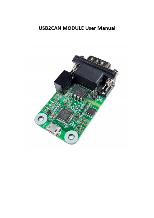
USB2CAN MODULE User ManualUSB2CAN module is a‘plug and play’and bi-directional port powered USB to CAN converter which realizes long-distance communication between your Raspberry Pi/SBC/PC and other devices stably though CAN-Bus connection.With small size and convenient operation,It’s a cost-effective solution that are safe and reliable for all your data-conversion/device-protection applications for any experienced engineer interfacing to expensive industrial equipment yet simple enough for home use by an amateur hobbyist.USB2CAN can also be applied to obtain the data of car via the OBD connector,but you need to configured and secondary development by yourself.2.patible with Raspberry Pi Zero(W)/Pi3B+/PI4/Beaglebone/Tinker Board and any single board computer.2.Plug and Play USB device.No external power required.Support wider CAN baud rate,From 20Kbps to1Mbps can be programmed arbitrarily.3.On board STM32F0microcontroller,high speed data transfer with DMA technique.Support for CAN bus2.0A and2.0B specification.4.Power supply isolation,signal input/output isolation,Built-in surge and static protection.120 Ohm resistor selectable jumper feature.es with C/Python demos of Socket-CAN,detailed user manual and friendly technology support.4.1CAN connectorPinout4.2120Ohm Resistor Setting.A High-speed CAN bus (ISO 11898-2)must be terminated on both ends with 120Ohms.The USB2CAN module with a on-board 120Ωselectablejumer.Disable 120Ohm Resistor.Enable120Ohm Resistor.4.3LEDIndicate5.Run USB2CAN Test DemoUSB2CAN module can run properly without any additional driver request on all Linux system since version3.9.such as Ubuntu,Debian and Raspbian.If you meet problems in older system, You need to reconfigure the kernel drivers.Enable‘gs_usb.c’and install‘gs_usb.ko’into system. So notice that if you only compile this drivers,It may fail to load in system.At this time,compile fully with new configure.You can test the USB2CAN module any single board computer or PC with the right Linux version. We take Raspberry Pi4as an example to show you how to run the C/Python and can-utils demo.5.1Preparatory work5.1.1ConnectionThere are two way to test the USB2CAN module.One is plug two USB2CAN module into the USB Host of each Raspberry Pi.The other is plug two USB2CAN into one Raspberry Pi.But the codes and commands are a little bit different.And then connect the CAN_H pin and CAN_L pin to eachother.No GND pin connection requirement.Methods A Methods BUse two Raspberry Pi to test USB2CAN Use one Raspberry Pi to test USB2CAN 5.1.2ifconfig-aType command‘ifconfig-a’to check‘can0’device is available in system.If you plug two USB2CAN into one Raspberry PI,You will see one more‘can1’device.5.1.3demsgYou can type command‘demsg’for see more information about USB2CAN module at the bottom.5.2Use can-utils toolThis tool is a very easy way to test CAN commuincation by only type two command.5.2.1Install Toolssudo apt-get install can-utils5.2.2Initialize CAN portsudo ip link set can0type can bitrate125000sudo ifconfig can0up5.2.3Set one as receivercandump can05.2.4Set the other as sendercansend can0123#12345678905.2.5Test two module on one Raspberry PiDo as above steps,set‘can0’as receiver and‘can1’as sender.5.3Run C Demo(1)Load C Demo named‘usb2cantest’from our Wiki and up-zip it to the desktop of Rasbian./wiki/doku.php?id=usb_canOr /wiki/doku.php(2)Go to folder named‘c’and change the permissions.chmod-R a+x*(3)Set one as receiver,execute following commands in serial terminal.Now this Raspberry pi is blocked../can0_receive(4)Set the other Pi as sender,execute following commands../can0_send(5)You should see that the receiver has received the packet.(6)You also can plug two USB2CAN module on one Raspberry PI board to test.You should see two can socket“can0”and“can1”devices.So notice that you need to change“can0”to“can1”when you use“can1”device.5.4Run Python3DemoDownload Python Demo named‘python3’from our Wiki and up-zip it to Desktop(or wherever you want put it)./wiki/doku.php?id=usb_canOr /wiki/doku.phpThere are three files in the folder.‘send.py’and‘receive.py’is for you use two Raspberry Pi to test,and‘test.py’is for you use one Raspberry Pi and two USB2CAN module to test.(1)Check the Python version of your Raspbian.Python3.7.3default in2019-09-26-Raspbian.img. Our Demo can run on any Python3version.python3-V(2)If you can’t find the Python3in system.Install the Python3sudo apt-get install python3-pip(3)Install Python CAN library.sudo pip3install python-can(4)Set one Raspberry Pi as receiver.sudo python3receive.py(5)Set the other as sender.sudo python3receive.py(6)You will see the data received.(7)If you use one Raspberry Pi and two USB2CAN modeule for testing.Run‘test.py’and check the result.sudo python3test.py6.Now with previous demo’s code to show you how to program socket can in Raspbian with C and Python.The socket can is an implementation of CAN protocols(Controller Area Network)for Linux.CAN is a networking technology which has widespread use in automation,embedded devices,and automotive fields.While there have been other CAN implementations for Linux based on character devices,Socket CAN uses the Berkeley socket API,the Linux network stack and implements the CAN device drivers as network interfaces.The CAN socket API has been designed as similar as possible to the TCP/IP protocols to allow programmers,familiar with network programming,to easily learn how to use CAN sockets.For more Socket CAN detail please refer to below link:https:///doc/Documentation/networking/can.txt6.1Programming in C6.1.1For Sender’s codes(1):Create the socket,If an error occurs then the return result is-1.(2):Locate the interface to“can0”or other name you wish to use.The name will show when you execute“./ifconfig–a”.(3):Bind the socket to“can0”.(4):Disable sender’s filtering rules,this program only send message do not receive packets.(5):Assembly data to send.(6):Send message to the can bus.You can use the return value of write()to check whether all data has been sent successfully.(7):Close can0device and disable socket.6.2.3For Receiver’s codes(1)step1and(2)is same as Sender’s code.(3):It’s different from Sender’s.(4):Define receive filter rules,we can set more than one filters rule。


USBCAN II调试器用户手册V5.0目录一、功能特点 (2)二、硬件参数 (3)2.1外观 (3)2.2参数 (3)2.3软件支持 (3)2.4产品清单 (4)2.5典型应用 (4)三、设备安装 (5)3.1供电模式 (5)3.2CAN接线端 (5)3.3信号指示灯 (6)3.4终端电阻 (6)3.5内部接口介绍 (7)3.6驱动程序安装 (7)四、工具软件使用 (11)五、产品服务 (21)5.1系统升级 (21)5.2技术支持 (21)一、功能特点USBCAN II调试器带有2路CAN接口,PC可以通过USB总线连接到一个标准的CAN 网络中,构建现场总线测试实验室,工业控制,智能楼寓,汽车电子等领域中数据处理,数据采集,数据通讯网络的CAN核心控制单元;USBCAN II调试器可以被作为一个标准的CAN节点,是CAN总线产品开发,CAN总线设备测试,数据分析的强大工具;同时,USBCAN II调试器具有体积小、方便安装等特点,也是便携式系统用户的最佳选择;USBCAN II调试器可以利用本店提供的CANMonitor工具软件,直接进行CAN总线的配置,发送和接收。
用户也可以参考本店提供的DLL动态连接库、例程编写自己的应用程序,方便的开发出CAN系统应用软件产品;USBCAN II调试器设备中,CAN总线电路采用独立的DCDC电源模块,进行光电隔离,使该接口适配器具有很强的抗干扰能力,大大提高了系统在恶劣环境中使用的可靠性。
二、硬件参数2.1外观2.2参数USB与CAN总线的协议转换;USB接口支持USB2.0,兼容USB1.1;支持2路独立CAN通道;支持CAN2.0A和CAN2.0B协议,支持标准帧和扩展帧;支持双向传输,CAN发送、CAN接收;支持数据帧,远程帧格式;CAN控制器波特率在20Kbps-1Mbps之间可选,也软件配置特殊波特率;CAN收发器采用的是工业级磁耦芯片隔离,具有2500V的隔离电压;CAN控制器带有32个硬件FIFO接收缓冲器,每个通道最高接收能力可达3000帧/秒; CAN控制器带有16个硬件接收滤波器,可通过软件进行配置;USB总线直接供电;工作温度:0~70℃;外壳尺寸:98*78*30mm;2.3软件支持USBCAN II调试器拥有自己的USBCAN驱动库,支持WIN98、WIN2000和XP操作系统。

广州致远电子股份有限公司CANalyst-II+用户手册CAN-bus 总线分析仪类别内容关键词CANalyst-II+ 分析仪 摘要CANalyst-II+产品描述与使用指导修订历史版本日期原因V1.00 2015/06/26 创建文档目录1. 功能简介 (1)1.1产品概述 (1)1.2功能特点 (1)1.3典型应用 (2)2. 设备安装 (3)2.1供电模式 (3)2.1.1外部电源供电模式 (3)2.1.2USB总线供电模式 (3)2.2CAN-bus连接器 (3)2.3信号指示灯 (3)2.4系统连接 (4)2.4.1CAN总线连接 (4)2.4.2总线终端电阻 (5)2.4.3USB总线连接 (5)3. 软件安装及使用 (6)3.1系统要求 (6)3.2软件安装 (6)3.3初次使用指南 (6)4. 常见问题 (12)5. 检查和维护 (15)6. 附录:CAN2.0B协议帧格式 (16)7. 免责声明 (18)1. 功能简介1.1 产品概述CANalyst-II+高性能CAN接口卡是与USB2.0总线全速规范兼容的,集成1~2路CAN 接口的高性能型CAN-bus总线通讯接口卡。
采用CANalyst-II+高性能CAN接口卡,PC可以通过USB总线连接至CAN-bus网络,构成现场总线实验室、工业控制、高性能小区、汽车电子网络等CAN-bus网络领域中数据处理、数据采集的CAN-bus网络控制节点。
CANalyst-II+高性能CAN接口卡是CAN-bus产品开发、CAN-bus数据分析的强大工具;同时,具有体积小巧、即插即用等特点,也是便携式系统用户的最佳选择。
CANalyst-II+接口卡上自带电气隔离模块,使接口卡避免由于地环流的损坏,增强系统在恶劣环境中使用的可靠性。
CANalyst-II+高性能CAN接口卡支持Win2000/XP等操作系统,也支持Linux2.6版版本的操作系统。
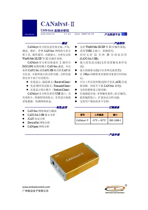
CANalyst-Ⅱ ——————————————产品特性 支持Win98/Me/2K/XP 等32位操作系统; 采用USB1.1接口,即插即用;同时支持11位和29位的标识符(CAN2.0A/2.0B);强大的发送功能(支持设置触发条件发送);强大的接收功能(可以多种过滤设置); 以100μs 的解析度对接收对象进行时间标记;可以工作在监听模式(即不发送ACK 位或错误帧,因此不干扰CAN-bus 系统); 支持检测和显示错误帧; 在线跟踪存盘,多种触发条件,前/后触发; 提供编程接口,扩展协议分析功能; 支持用户模块的多个实例。
————————————典型应用 z CAN-bus 网络调试与测试z CAN2.0A/2.0B 报文分析z i CAN 协议分析z DeviceNet 网络分析z CANopen 网络分析—————————————订购信息型号 工作温度接口 CANalyst -Ⅱ-25°C ~ +85°C ISO 11898-2————————————————————————————————产品外观——————————————概述 CANalsyt-Ⅱ分析仪是用来安装、开发、测试、维护、管理CAN-bus 网络的专业分析工具,操作通用,功能强大。
分析仪支持Win98/Me/2K/XP 等32位操作系统。
CANalsyt-Ⅱ分析仪集成有2路符合ISO11898标准的独立CAN-bus 通道,可以处理CAN2.0A 或CAN2.0B 格式的CAN 报文信息,并提供强大的分析功能。
分析仪提供有多个客户应用程序:z 在线显示、跟踪报文(ReceiveClient )z 发送/循环发送报文(TransmitClient )z 在线显示统计数字(StatisticClient )CANalsyt-Ⅱ分析仪采用USB 接口,具有体积小、即插即用的特点,非常适合现场采集数据,检测网络状态。
contents1 Introduction (4)1.1 Description (4)1.2 Features (4)1.3 External interfaces (4)1.4 Applications (4)1.5 Supporting Operating System (5)1.6 Using Environment (5)2 Technical Support (5)3 About Function (5)3.1 Summary (5)3.2 Parameters (5)3.3 Appearance (6)4 Using Product (6)4.1 Power supply (6)4.2 CAN-bus connector (7)4.3 Signal Indicator LED (7)5 System Connection (8)5.1 CAN-bus Connection (8)5.2 USB Connection (9)6 Version Information (10)Appendix 1: The Frame Format of CAN2.0 (11)Appendix 2: SJA1000 Standard Baud Rate (13)Appendix 3: Configuration for CAN Message Filter (14)Appendix 4: CAN-bus Communication distance(Reference Value) (20)Appendix 5: list of CAN-bus products (21)1 Introduction1.1 DescriptionUSBCAN-2I intelligent module integrates two isolate CAN-bus interfaces. With USB interface, it can transfers data from PC and CAN-bus. The CAN-bus interfaces accord with the CAN Specification 2.0A/B, and it supports the any baud rate from 5Kbps to 1Mbps. It has perfect protection function and high reliability asa CAN-bus node.1.2 FeaturesCAN: Supports CAN Specification 2.0A/B, Conforms to ISO/DIS11898;USB: Supports USB2.0, Compatible with USB1.1;Baud Rate:From 5K bps To 1Mbps;Power: USB port or an external power supply(DC5V and ≥500mA).1.3 External interfacesUSB:Connector of USB-B;CAN:The 3 Pin open Connector;Terminal Resistance:With the dip switch.1.4 ApplicationsCAN-bus Data Analysis;Adjustment of CAN-bus Equipment;Expanding the CAN-bus Nodes.1.5 Supporting Operating SystemWindows98/Me/2000/XP/2003;Linux 2.4、Linux 2.6.1.6 Using EnvironmentOperating Temperature: -25°C ~ +85°C;Storage Temperature: -40°C ~ +85°C.2 Technical SupportIf you want get technical support or the latest information about this product, please access the website: http:/.3 About Function3.1 SummaryUSBCAN-2I intelligent CAN interface module made in iTEK. It is convenient to Using it for collecting data, and analysing data, and processing data in building CAN-bus laboratory, or industrial control, or intelligent community, or automotive electronics. USBCAN-2I has these characteristics, such as compact design and beautiful appearance and plug-and-play etc, and it is dependable assistant in matching equipment and debugging equipment and developing equipment.3.2 ParametersAdopts electrical isolation, the isolation voltage is : 2500Vrms;Max data flow for a single channel: 3000 fps (standard frame);Power consumption: ≤2W.Physical size: (length) 100mm * (width) 65mm * (height) 25mm.Supports iTEK CANalyst software.3.3 Appearance4Using Product4.1 Power supplyIt can be powered by either PC USB port or an external DC5V power supply.Using USB port power supply:Connecting the USBCAN-2I module to the PC with the attached cable can provide the module with a +5V voltage. Firstly, the LED POWER becomes to green,indicating the power supply works normally.External DC5V Power Supply:External power supply is used in case that the USB port is unable to provideenough current for USBCAN-2I interface when the PC is using an USB hub or connected with many USB terminal devices.When the external power supply (DC5V@500mA, Inner pin is positive andoutside is negative) is connected to the POWER jack of the USBCAN-2I module,the LED POWER becomes to green. Now, user only need to connect the USBCAN-2I module to the PC with the attached USB cable to start the module.4.2 CAN-bus connectorUSBCAN-2I module integrates two independent CAN-bus channels, and they are can be connected with two different CAN network. The pin signal definitions for CAN port, please see Table 1.Table 1 Pin Signal Definitions for CANPin Channel Definition Function1CAN0 H CAN_H signal cable2 GShieldcable3 L CAN_L signal cable1CAN1H CAN_H signal cable2 GShieldcable3 L CAN_L signal cable4.3 Signal Indicator LEDUSBCAN-2I module integrates three signal indicator LEDs, they are PWR and ERR and CAN0/CAN1. Detailed function, please see Table 2.When USBCAN-2I module is power up, the PWR LED becomes green, indicating that the power supply is working. Then the ERR LED and the CAN0/CAN1 LED flashes red with same frequency, indicating that the inner MCU is working and waiting for starting. When the software starts the any CAN channel, the ERR LED and the CAN0/CAN1 LED stops flashing and in turn off status. Indicatingthat the USBCAN-2I module is ready for data transmission .Table 2 LEDs StatusDefinition Color Status FunctionPWR GREEN LIGHT Power supply is OK.ERRCAN-busFLASHERR REDRED FLASH Data transmission in CAN0 channel.CAN0/CAN1GREEN FLASH Data transmission in CAN1 channel.5System Connection5.1 CAN-bus ConnectionTo connect USBCAN-2I module to the CAN-bus, user only need to connectCAN_L and CAN_L, CAN_H and CAN_H. CAN-bus network adopts straight-line topology, and two terminal 120Ω resistances need to be installed on the two bus terminals. If the number of nodes larger than 2, the 120Ω resistance is notnecessary to be installed on the middle node. The module integrates two terminal 120Ω resistances for two CAN channels. You can enable them with the dip switch.The usage, please see Table 3.Table 3 Dip Switch Status definitionSwitch ChannelStatusFunctionR0 CAN0ONEnable the 120Ω resistance. OFF Disable the 120Ω resistance. R1 CAN1ONEnable the 120Ω resistance. OFFDisable the 120Ω resistance.Note: CAN-bus cable can be either ordinary twisted-pair or shield twisted-pair. If the communication distance is longer than 1Km, then the area of section for the twisted-pair should be larger than Φ1.0mm 2. The particular specification depends upon the communication distance, and a longer distance usually requires a larger area.5.2 USB ConnectionThe USB port of USBCAN-2I supports USB1.1 protocol specification, and can be used to connect PCs that support USB1.1 and USB2.0 standards. There are two modes for USBCAN-2I interface connecting to PC: Bus power supply:Directly connects to USB port on the PC by using the attached USB cable. This USB port provides +5V voltage to USBCAN-2I module. External power supply:USBCAN-2I interface module connects to the PC USB hub. If this USB hub is powered by bus, USBCAN-2I module should use external power supply. Then connects to USB port on the USB hub by using the attached USB cable.6 Version InformationVersion Add/Del/Rev DataVersion 2012-11-15 V1.00 InitialAppendix 1: The Frame Format of CAN2.0CAN2.0B standard frame:The length for CAN standard frame message is 11 bytes, including two parts: message and data. The first 3 bytes are used for message.。
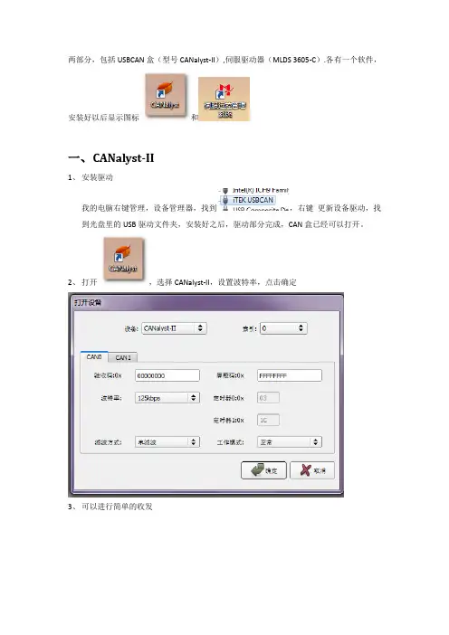
两部分,包括USBCAN盒(型号CANalyst-II),伺服驱动器(MLDS 3605-C).各有一个软件,
安装好以后显示图标和
一、C ANalyst-II
1、安装驱动
我的电脑右键管理,设备管理器,找到,右键更新设备驱动,找到光盘里的USB驱动文件夹,安装好之后,驱动部分完成,CAN盒已经可以打开。
2、打开,选择CANalyst-II,设置波特率,点击确定
3、可以进行简单的收发
二、伺服管理软件
1、打开软件,选择驱动器型号,点击选择
2、选择连接类型,设置波特率,所有主从设备的波特率必须统一。
打开设备
3.点击“搜索节点”(下图为搜索前和搜索后),发现设备
3、选中节点,打击左上角连接设备(上图),此时软件右边开始列出电机状态(下图)
4、点选标签页PID设置,可以设置或获取PID
5、对电机进行简单的控制,并可以监测电机去行状态。
USBCAN II调试器用户手册V5.0目录一、功能特点 (2)二、硬件参数 (3)2.1外观 (3)2.2参数 (3)2.3软件支持 (3)2.4产品清单 (4)2.5典型应用 (4)三、设备安装 (5)3.1供电模式 (5)3.2CAN接线端 (5)3.3信号指示灯 (6)3.4终端电阻 (6)3.5内部接口介绍 (7)3.6驱动程序安装 (7)四、工具软件使用 (11)五、产品服务 (21)5.1系统升级 (21)5.2技术支持 (21)一、功能特点USBCAN II调试器带有2路CAN接口,PC可以通过USB总线连接到一个标准的CAN 网络中,构建现场总线测试实验室,工业控制,智能楼寓,汽车电子等领域中数据处理,数据采集,数据通讯网络的CAN核心控制单元;USBCAN II调试器可以被作为一个标准的CAN节点,是CAN总线产品开发,CAN总线设备测试,数据分析的强大工具;同时,USBCAN II调试器具有体积小、方便安装等特点,也是便携式系统用户的最佳选择;USBCAN II调试器可以利用本店提供的CANMonitor工具软件,直接进行CAN总线的配置,发送和接收。
用户也可以参考本店提供的DLL动态连接库、例程编写自己的应用程序,方便的开发出CAN系统应用软件产品;USBCAN II调试器设备中,CAN总线电路采用独立的DCDC电源模块,进行光电隔离,使该接口适配器具有很强的抗干扰能力,大大提高了系统在恶劣环境中使用的可靠性。
二、硬件参数2.1外观2.2参数USB与CAN总线的协议转换;USB接口支持USB2.0,兼容USB1.1;支持2路独立CAN通道;支持CAN2.0A和CAN2.0B协议,支持标准帧和扩展帧;支持双向传输,CAN发送、CAN接收;支持数据帧,远程帧格式;CAN控制器波特率在20Kbps-1Mbps之间可选,也软件配置特殊波特率;CAN收发器采用的是工业级磁耦芯片隔离,具有2500V的隔离电压;CAN控制器带有32个硬件FIFO接收缓冲器,每个通道最高接收能力可达3000帧/秒; CAN控制器带有16个硬件接收滤波器,可通过软件进行配置;USB总线直接供电;工作温度:0~70℃;外壳尺寸:98*78*30mm;2.3软件支持USBCAN II调试器拥有自己的USBCAN驱动库,支持WIN98、WIN2000和XP操作系统。
如何兼容使用周立功CANTest软件说明书说明书版本:V2.03更新日期:2016.06.15首先感谢您购买和使用本公司的产品,本公司将始终竭诚为您服务!本文档的目的在于指导第一次购买使用USB-CAN适配器/CANalyst-II分析仪的用户如何兼容使用周立功USB_CAN设备的上位机软件,即CANTest。
一、安装周立功CANTest软件1、软件的下载用户可以自行到周立功的官方网站上下载免费的CANTest软件。
下载地址:/can/down/down/id/22.html在资料下载栏目下,可以下载到最新的CANTest软件。
软件安装与使用,请参照光盘目录下的《1.如何兼容使用周立功CANTest软件.pdf》、《CANTest使用说明书V3.04.pdf》说明文档。
运行CANTest_Setup_V2.xx.exe开始安装:1232、将CANTest安装目录下的“ControlCAN.dll”文件名改为“ControlCAN.dll.bak”,作为备份;ZLG的dll文件信息43、将本公司提供的光盘目录下的[二次开发库文件]文件夹中的ControlCAN.dll复制到CANTest的安装目录下;4、打开并运行CANTest.exe,在正确安装了本公司的USB_CAN适配器的驱动程序后,即可通过CANTest软件进行操作了。
5注意:1、型号建议选择ZLG最新的USBCAN型号:USBCAN-2E-U。
2、DBC协议解析功能,只能选择USBCAN-2E-U型号,其它型号不支持该功能。
3、解析汽车J1939协议,直接选择USBCAN-2E-U型号,用DBC解析功能。
4、关于DBC解析功能,请参照《15.附件8:如何解析和破解车载CAN协议--DBC协议.docx》说明文档。
65、若需要再使用周立功的USBCAN适配器,可将备份的“ControlCAN.dll.bak”文件改回“ControlCAN.dll”并覆盖替换现有的同名文件。
USBCAN-II SUSB-CAN转换器用户手册文档版本:V1.0(2017/04/19)目录目录 (2)1.功能简介 (3)1.1功能概述 (3)1.2性能特点 (3)1.3典型应用 (3)2.设备安装 (4)2.1设备尺寸 (4)2.2接口定义及功能 (4)2.3驱动及软件安装 (5)3.设备使用 (7)3.1与PC连接 (7)3.2与CAN-bus连接 (7)3.3CAN总线终端电阻 (8)3.4系统状态指示灯 (8)4.CAN Test软件使用 (10)4.1软件启动 (10)4.2数据收发 (11)4.3DBC文件解析功能 (11)4.4其他功能 (12)5.CAN Pro软件使用 (13)6.二次开发 (14)7.技术规格 (15)8.常见问题 (16)附录CAN2.0B协议帧格式 (19)1.功能简介1.1功能概述USBCAN-II S是集成2路CAN接口的非工业级CAN-bus总线通讯接口卡。
该型号CAN卡可兼容USB2.0总线全速规范,采用USBCAN-II S接口卡,PC 可以通过USB接口快速连接至CAN-bus网络,构成现场总线实验室、工业控制、智能小区、汽车电子网络等CAN-bus网络领域中数据处理、数据采集的CAN-bus 网络控制节点。
USBCAN-II S接口卡是CAN-bus产品开发、CAN-bus数据分析的强大工具;同时具有体积小巧、即插即用等特点,也是便携式系统用户的最佳选择。
USBCAN-II S接口卡上自带CAN接口电气隔离保护模块,使其避免由于瞬间过流/过压而对设备造成损坏,增强系统在恶劣环境中使用的可靠性。
USBCAN-II S接口卡支持Win2000/XP/Win7/Win8等32位/64位操作系统。
我公司为用户提供统一的应用程序编程接口和完整的应用示范代码,含VC、VB、Net、Delphi、Labview和C++Builder等开发例程示范,方便用户进行应用程序开发。
CANalyst-Ⅱ+分析仪CAN通信网络协议分析全能助手CANalyst-Ⅱ+分析仪是广州致远电子股份有限公司全新推出的一款用于安装,开发,测试,维护,管理CAN-bus网络的专业分析工具。
可处理CAN2.0A和CAN2.0B格式的CAN报文信息,通过配套的CANPro协议分析平台软件,提供对CAN底层协议分析、CANOpen协议分析、DeviceNet协议分析、SAE J939协议分析、iCAN 协议分析及自定义协议分析的支持。
②规格参数•USB接口支持USB1.1,USB1.1,USB2.0和USBOTG规范;•USB总线供电,供电不足时可使用外接电源;•CAN通道支持CAN2.0A与CAN2.0B协议,符合ISO/DIS 11892-1/2/3标准;•可编程任意设置CAN波特率,范围在5Kbps~1Mbps之间;•CAN接口EMC等级:接触放电±8KV,群脉冲±2KV;•CAN通道采用电磁隔离,隔离电压:2500VDC;•工作温度:-40℃~85℃;•可用于有安全防爆需求的环境中;②产品功能1.CAN底层协议分析与控制操作CANalyst-II+可准确接收总线网络上的CAN帧数据,同时也可向CAN线网络中发送数据,确保通讯具有一个可靠的数据传输通道。
设备免费提供上位机接口函数动态库文件,用户也可自己开发相关程序,如图1. 1所示:图1. 1 CAN底层协议的数据收发2.CAN总线波特率探测:在某些场合中,也许会不知道现场CAN总线网络中的波特率是多少,则平常的CAN总线分析仪将无法获取到网络中的数据,更不用谈及总线测试分析了,这个时候即使是经验丰富的工程师也将无从下手。
CANalyst-II+的总线波特率自动探测功能则可快速准确检测出现场总线的通信波特率,让所有的CAN通信测试踏出关键的第一步,如图2. 1和图2. 2所示:图2. 1 探测总线波特率图2. 2 CAN波特率自动探测操作3.CAN总线状态分析:如何搭建一个可靠的CAN通信网络,无错误帧和合适的通信流量控制是关键。
目录1 产品介绍 (4)1.1 产品概述 (4)1.2 产品特性 (4)1.3 接口形式 (4)1.4 产品应用 (4)1.5 操作系统支持 (5)1.6 使用环境 (5)2 技术支持 (5)3 产品功能 (5)3.1 概述 (5)3.2 参数指标 (5)3.3 产品外观 (6)4 设备使用 (6)4.1 设备供电 (6)4.2 CAN总线连接 (7)4.3 指示灯 (7)5 系统连接 (8)5.1 CAN-BUS连接 (8)5.2 USB总线连接 (9)6 修订历史 (9)附录1 CAN2.0B协议帧格式 (10)附录2 标准波特率设置 (12)附录3 CAN报文滤波器设置 (13)附录4 CAN总线通信距离(参考值) (18)1产品介绍1.1 产品概述CANalyst-II分析仪是用来安装、开发、测试、维护、管理CAN-bus网络的专业分析工具,操作通用,功能强大。
CANalyst-II分析仪集成有2路符合ISO11898标准的独立CAN-bus通道,可以处理CAN2.0A或CAN2.0B格式的CAN报文信息,并提供强大的分析功能;CANalyst-II分析仪采用USB接口,具有体积小、即插即用的特点,非常适合现场采集数据,检测网络状态。
CANalyst-II的标配软件,提供对CAN底层协议分析、iCAN协议分析、DeviceNet协议分析、CANopen 协议分析以及SAE J1939协议分析的支持。
1.2产品特性¾CAN:适用CAN2.0A/B, 符合 ISO11898规范;¾USB:适用USB2.0,符合 USB1.1协议规范;¾波特率:5Kbps~1Mbps之间任意设定;¾电源:USB供电或外接DC5V供电(≥500mA)。
1.3接口形式¾USB:USB B型座;¾CAN:3位菲尼克斯端子;¾端接电阻:拨码开关。
1.4产品应用¾CAN总线数据分析;¾CAN通信设备调试;¾CAN网络节点扩展。
USB-CAN总线接口适配器CANalyst-II分析仪使用说明书说明书版本:V1.90说明书更新日期:2014.05.01目录第一章产品简介 (1)1.1 概述 (1)1.2 性能与技术指标 (1)1.3 典型应用 (2)1.4 产品销售清单 (2)1.5 技术支持与服务 (3)1.6 产品选型 (3)第二章外形与接口描述 (4)2.1 外观与接口 (4)2.2 信号定义 (5)2.3 出厂配置 (6)第三章安装USB_CAN Tool软件 (7)3.1 驱动程序安装 (7)3.2 USB-CAN Tool软件 (18)3.3 软件操作与功能介绍 (19)3.4 自发自收测试 (22)3.5 多个USB-CAN设备同时使用 (22)第四章附录 (23)4.1 CAN2.0B标准帧格式. (23)4.2 CAN2.0B扩展帧格式 (24)I第一章产品简介1.1 概述USB-CAN-2(A/C)总线适配器是带有USB2.0接口和2路CAN接口的CAN总线适配器。
CANalyst-II分析仪是带有USB2.0接口和2路CAN接口的CAN总线适配器,具备CAN总线协议分析功能,支持SAE J1939、DeviceNet、CANopen、iCAN以及自定义高级协议分析功能,兼容周立功的CANPro软件。
可进行双向传送。
USB-CAN总线适配器/CANalyst-II分析仪可以被作为一个标准的CAN节点,是CAN总线产品开发、CAN总线设备测试、数据分析的强大工具。
采用该接口适配器,PC可以通过USB接口连接一个标准CAN网络,应用于构建现场总线测试实验室、工业控制、智能楼宇、汽车电子等领域中,进行数据处理、数据采集、数据通讯。
同时,USB-CAN接口适配器/CANalyst-II分析仪具有体积小、方便安装等特点,也是便携式系统用户的最佳选择。
USB-CAN-2A接口适配器设备,CAN总线未隔离,由USB直接供电。
目录1 产品介绍 (4)1.1 产品概述 (4)1.2 产品特性 (4)1.3 接口形式 (4)1.4 产品应用 (4)1.5 操作系统支持 (5)1.6 使用环境 (5)2 技术支持 (5)3 产品功能 (5)3.1 概述 (5)3.2 参数指标 (5)3.3 产品外观 (6)4 设备使用 (6)4.1 设备供电 (6)4.2 CAN总线连接 (7)4.3 指示灯 (7)5 系统连接 (8)5.1 CAN-BUS连接 (8)5.2 USB总线连接 (9)6 修订历史 (9)附录1 CAN2.0B协议帧格式 (10)附录2 标准波特率设置 (12)附录3 CAN报文滤波器设置 (13)附录4 CAN总线通信距离(参考值) (18)1产品介绍1.1 产品概述CANalyst-II分析仪是用来安装、开发、测试、维护、管理CAN-bus网络的专业分析工具,操作通用,功能强大。
CANalyst-II分析仪集成有2路符合ISO11898标准的独立CAN-bus通道,可以处理CAN2.0A或CAN2.0B格式的CAN报文信息,并提供强大的分析功能;CANalyst-II分析仪采用USB接口,具有体积小、即插即用的特点,非常适合现场采集数据,检测网络状态。
CANalyst-II的标配软件,提供对CAN底层协议分析、iCAN协议分析、DeviceNet协议分析、CANopen 协议分析以及SAE J1939协议分析的支持。
1.2产品特性¾CAN:适用CAN2.0A/B, 符合 ISO11898规范;¾USB:适用USB2.0,符合 USB1.1协议规范;¾波特率:5Kbps~1Mbps之间任意设定;¾电源:USB供电或外接DC5V供电(≥500mA)。
1.3接口形式¾USB:USB B型座;¾CAN:3位菲尼克斯端子;¾端接电阻:拨码开关。
1.4产品应用¾CAN总线数据分析;¾CAN通信设备调试;¾CAN网络节点扩展。