Quasi-phase-matching of laser harmonics using
- 格式:pdf
- 大小:1.08 MB
- 文档页数:10

首字母英文中文索引A absolute error 绝对误差absorbing clamp 吸收钳AC-DC comparator 交流一直流比较仪AC-DC conversion 交流一直流转换AC-DC converter 交流一直流转换器adjacent channel selectivity 邻频道选择性alternating component 交流分量apparent power 视在功率appliance impedance 设备阻抗artificial hand 模拟手artificial mains network 人工电源网络asymmetrical control (single phase) 不对称控制(单相)asymmetrical terminal voltage 不对称端子电压average detector 平均值检波器average power 有功功率B balun 平衡-不平衡转换器bandwidth(of a device) (设备的)带宽bandwidth(of an emlssion or signal) (发射或信号的)带宽basic range 基本量程broadband device 宽带设备broadband disturbance 宽带骚扰burst firing control 猝发导通控制burst(of pluses or oscillations) 猝发(脉冲或振荡)C cabinet radiation 壳体辐射class index 级别指数click 喀呖声click rate 喀呖声率combination method of measurement 组合测量法common mode current 共模电流common mode impedance 共模阻抗common mode interference 共模于扰common mode rejection ratio 共模抑制比common mode voltage 共模电压common mode voltage 共模电压commutation notch 换相缺口commutation notch 换相缺口conductance 电导conducted disturbance 传导骚扰conductor 导体contact electromotive force 接触电动势contact potential (difference) 接触电位(差)continuous disturbance 连续干扰continuous noise 连续噪声coupling factor 耦合系数coupling path 耦合路径crossmodulation 交调current 电流current probe 电流探头cycle 周期cycle of operation 工作周期cyclic on/off switching control 周期性通/断开关控制D damped oscillatory wave 阻尼振荡波dead band 死区degradation(of performance) (性能)降低delay angle 延迟角delta network △形网络desensitization 灵敏度降低dielectric strength 介电强度differential mode current 差模电流differential mode voltage 差模电压discontinuous disturbance 断续干扰discontinuous disturbance 断续骚扰disturbance field strength 骚扰场强disturbance power 骚扰功率disturbance suppression 骚扰抑制disturbance voltage 骚扰电压dummy lamp 模拟灯duration of a voltage change 电压变化持续时间E earth-coupled interference; ground-coupledinterference地耦合干扰effective radiated power(of any device inagiven direction)(装置在给定方向上的)有效辐射功率effective selectivity 有效选择性electrical charge time constant(of adetector)(检波器的)充电时间常数electrical zero 电零位electricity 电electromagnetic compatibility margin [电磁]兼容裕量electromagnetic compatibility; EMC 电磁兼容性electromagnetic disturbance 电磁骚扰electromagnetic disturbance level [电磁]骚扰电平electromagnetic emission [电磁]发射electromagnetic environment 电磁环境electromagnetic interference;EMI 电磁干扰electromagnetic noise 电磁噪声electromagnetic radiation [电磁]辐射electromagnetic screen 电磁屏蔽electromagnetic susceptihility [电磁]敏感度electromotive force 电动势electrostatic discharge;ESD 静电放电electrostatic screen 静电屏蔽eletrical discharge time constant(of a(检波器的)放电时间常数detector)eletromagnetic compatibility level [电磁]兼容电平emission level(of a disturbance source) (骚扰源的)发射电平emission limit(from a disturbance source) (骚扰源的)发射限值emission margin 发射裕量emission(in radio communication) (无线电通信中的)发射emitter(of electromagnetic disturbance) (电磁骚扰的)发射体external immunity 外部抗扰度F flicker 闪烁flickermeter 闪烁计floating input 浮置输人fundamental factor 基波因数fundamental(component) 基波[分量]fusion frequency 停闪频率G generalized phase control 广义相位控制ground(reference)plane 接地[参考]平面grunded input / earthed input 接地输人H harmonic (component) 谐波[分量]harmonic content 谐波含量harmonic number 谐波次数I image rejection ratio 镜频抑制比immunity (to a disturbance) (对骚扰的)抗扰度immunity level 抗扰度电平immunity limit 抗扰度限值immunity margin 抗扰度裕量immunity test level 抗扰度试验电平impedance 阻抗impulse 脉冲冲击impulsive disturbance 脉冲骚扰impulsive noise 脉冲噪声induced electromotive force 感应电(动)势information technology equipment;ITE 信息技术设备input power control 输入功率控制installation wiring impedance 设备连接线阻抗instantaneous value of an electric signal 电信号的瞬时值instrument constan 仪表常数insulation resistance 绝缘电阻insulator 绝缘体interference suppression 干扰抑制interfering signal 干扰信号intermediate frequency rejection ratio 中频抑制比intermodulation 互调internal immunity 内部抗扰度inter-system interference 系统间干扰ISM frequency band 工科医频段ISM(qualifier) 工科医(经认可的设备)L leakage current 泄漏电流level(of a time varying quantity) (时变量的)电平limit of disturbance 骚扰限值limit of interference 干扰限值line voltage regulation 电源电压调整率load regulation 负载调整率long-term flicker indicator 长时闪烁值M magnitude of a voltage fluctuation 电压波动幅度mains decoupling factor 电源去耦因数mains immunity 电源抗扰度mains-borne disturbance 电源骚扰man-made noise 人为噪声maximum limited current 最大限制电流mechanical time constant(of an indicating(指示仪表的)机械时间常数instrument)multicycle control( by half-cycles) 多周控制(按半周的)N narrowband device 窄带设备narrowband disturbance 窄带骚扰natural noise 自然噪声noise 噪声nth harmonic ratio 第n次谐波比O open circuit voltage 开路电压out of band emission 带外发射output impedance 输出阻抗output power control 输出功率控制over-current protection 过电流保护overload factor(of a receiver) (接收机的)过载系数over-voltage protection 过电压保护P parasitic oscillation 寄生振荡peak detector 峰值检波器peak value of an electric signal 电信号的峰值peak-ripple factor 纹波峰值因数permittivity 介电系数、电容率phase control 相位控制photoelectric effect 光电效应piezoelectric effect 压电效应point of common coupling;PCC 公共耦合点potential screen 电位屏蔽power factor 功率因数p-p value of an electric signal 电信号的峰一峰值professional equipment 专用设备program (of a control system) (控制系统的)程序protection ratio 保护率pulsating 脉动pulse 脉冲pulse response characteristic(of aquasi-peak voltmeter)(准峰值电压表的)脉冲响应特性Q quasi-impulsive 准脉冲噪声quasi-peak detector 准峰值检波器quasi-peak voltmeter 准峰值电压表R R.M .S (effective) value of a periodicquantity周期量的方均根值r.m.s-ripple factor 纹波均方根因数radiated disturbance 辐射骚扰radiation test site [辐射]测试场地radio environment 无线电环境radio frequency heating apparatus 无线电频率加热装置radio frequency interference;RFI 无线电频率干扰radio( frequency) noise 无线电[频率]噪声radio(frequency)disturbance 无线电[频率]骚扰random noise 随机噪声range-changing device 量程变换器rate of occurrence of voltage changes 电压变化发生率rate of rise 上升率rated value 额定值reactive power 无功功率reference impedance 参考阻抗relative voltage change 相对电压变化resistivity 电阻率reverse current protection 反向电流保护reverse voltage protection 反向电压保护ring wave 振铃波ripple 纹波ripple factor 纹波因数rise time(of a pulse) (脉冲的)上升时间root-mean-square detector 均方根值检波器S screen 屏蔽selectivity 选择性semiconductor 半导体sensitivity 灵敏度sensitivity threshold 灵敏度闹series mode interference 串模干扰series mode rejection ratio 串模抑制比series mode voltage 串模(干扰)电压service connection impedance 供电连接阻抗shielded enclosure 屏蔽壳体short interruption(of supply voltage) (供电电压的)短时中断short-circuit current 短路电流short-term flicker indicator 短时闪烁值signal-to-disturbance ratio 信骚比signal-to-noise ratio 信噪比single-signal method 单信号法spike 尖峰脉冲spurious emission(of a transmitting station) (发射台的)杂散发射spurious emission(of a transmitting) 接收机与发射机spurious response frequency 杂散响应频率spurious response rejection ratio 杂散响应抑制比stop(quarter-wave) filter [四分之一波长] 阻塞滤波器stripline 带状线superconductor 超导体supply system impedance 供电系统阻抗suppressor;suppression component 抑制器surface transfer impedance(of a coaxial(同轴线的)表面转移阻抗line)susceptible device 敏感装置symmetrical control (single phase) 对称控制(单相)symmetrical terminal voltage 对称端子电压synchronous multicycle control 同步多周控制T TEM cell 横电磁波室thermal converter 热电变换器thermoelectric effect 热电效应threshold of flicker perceptibility 闪烁感觉阈值threshold of flicker perceptibility 闪烁应激性阈值time constant of ac resistor 交流电阻时间常数total harmonic factor [总]谐波因数transfer impedance(of a screened circuit) (屏蔽电路的)转移阻抗transient(adjective and noun) 瞬态[的]two-signal method 双信号法U under-voltage protection 欠电压保护unwanted signal; undesired signal 无用信号V V-network V形网络voltage 电压voltage change interval 电压变化时间间隔voltage dip 电压暂降voltage dip 电压暂降voltage drop 电压降voltage fluctuation 电压波动voltage fluctuation waveform 电压波动波形voltage surge 电压浪涌voltage surge 电压浪涌voltage unbalance;voltage imbalance 电压不平衡voltage unbalance;voltage imbalance 电压不平衡voltage-reeulation coefficient 稳压系数V-terminal voltage V端子电压Z zero current 零电流。

物理英文术语及常用词汇物理英文术语及常用词汇为了方便广大考生更好的'复习,店铺整理了物理英语术语及常用词汇,以供各位考生考试复习参考。
希望对考生复习有所帮助。
物理英文术语及常用词汇篇1力 force重力 gravity摩擦力 friction拉力 traction质量 mass惯量 Interia加速度 acceleration力矩 torque静止 at rest相对 relative能量 energy动能 kenetic energy势能 potential energy功 work动量 momentum角动量 angular momentum能量守恒 energy conservation保守力 conserved force振动 vibration振幅 amplitude波 wave驻波 standing wave震荡 oscillation相干波 coherent wave干涉 interference衍射 diffraction轨道 obital速度 velocity速率 speed大小 magnatitude方向 direction水平 horizental竖直 vertical相互垂直 perpendicular坐标 coordinate直角坐标系 cersian coordinate system 极坐标系 polar coordinate system弹簧 spring球体 sphere环 loop盘型 disc圆柱形 cylinder电学磁学:电子 electron电荷charge电流 current电场 electric field电通量 electric flux电势electirc potential导体 conductor电介质 dieletric绝缘体 insultalor电阻 resistor电阻率 resistivity电容capacitor无穷 infinite横截面 cross ection匀强电场 uniform electric field分布 ditribution磁场 magnetic field磁通量 magnetic flux电感 inductance变压器 transformer频率 frequency周期 period电磁波 electomagnetic wave平面 plane热学:热平衡 thermal equilibrium理想气体 ideal gas热能 thermal energy热量 heat热容 heat capacity外界 surrounding准静态过程 quasi-static process等体过程 isochoric process等压过程 isobaric process等温过程 isothermal process绝热过程 adiabatic process循环 cycle光学光 light光程 optical path光强度 light intensity偏振 polarization 波长 wave length 传播 propagation量子力学(高中好像讲了一点点)原子 atomic 光子 photon光电效应 photo-electric effect物质波 matter wave光谱 spectrum激光 laser衰减 decay辐射 radiation械振动 mechanical vibration简谐振动 simple harmonic oscillation振幅 amplitude周期 period频率 ferquency赫兹 hertz单摆 simple pendulum受迫振动 forced vibration共振 resonnance机械波 mechanical wave介质 medium横波 transverse wave纵波 longitudinal wave波长 wavelength超声波 supersonic wave阿伏加德罗常数 Avogadro constant布朗运动 Brown mation热运动 thermal motion热力学能 thermal energy内能 internal energy热力学第一定律 first law of thermodynamics 能量守恒定律 law of conservation of energy热力学第二定律 second law of thermodynamics 各向同性 isotropy各向异性 anisotropy单晶体 single crystal(monocrystal)多晶体 ploycrystal表面张力 surface tension毛细现象 capillarity液晶 liquid crystal电荷 electric charge电荷量 queantity df electricity正电荷 positive charg负电荷 negative charg库仑定律 Coulomb law静电感应 electrostatic induction感应电荷 inducde charge元电荷 elementary charge电荷守恒定律 law of conservation of charge库仑(电荷单位) coulomb电场 electric fileld电场强度 electric field strength电场线 electric potential电势 electric potential电势差/电压 electric potential difference伏特 volt电容 capacitance电容器 capacitor法拉(电容单位) farad电流 electric current安培(电流单位) ampere电阻 resistance欧姆(电阻单位) ohm电动势 electormotive force(e.m.f.)半导体 semiconductor超导体 superconductor磁性 magnetism磁场 magnetic field磁感线 magnetic induction line安培定则 Ampere rule安培力 Ampere force磁感应强度 magnetic induction左手定则 left-hand rule洛伦兹力 Lorentz force磁通量 magnetic flux电磁感应 elctromagnetic induction感应电流 induction current感应电动势 induction electromotive force电磁感应定律 law of electromagnetic induction 右手定则 right-hand rule自感 self-induction交流 alternating current瞬时值 instantaneous value峰值 peak value有效值 effective value电感 inductance变压器 transformer电能 electric energy电磁场 electromagnetic field电磁波 electromagnetic wave雷达 radar光线 light ray平行光 parallel light实象 real image虚象 virtual image折射 refaction入射角 incident angle反射角 reflection angle折射角 diffraction angle折射率 diffraction index全反射 total reflection临界角 critical angle光导纤维 optical fiber棱镜 prism色散 dispersion光谱 spectrum波的衍射 diffraction of wave波的干涉 interference of waves 红外线 infrared ray紫外线 ultraviolet rayX射线 X-ray电磁波谱 electromagnetic effect 光电效应 photoelectric effect光子 photon普朗克常数 Planck constant波粒二象性 wave-particle duality 概率波 probability wave物质波 matter wave电子 electron质子 proton中子 neutron核子 nucleon同位数 isotope原子核 nucleus能级 energy level基态 ground state激发态 excited state跃迁 transition放射性 radioactivityα射线α rayβ射线β rayγ射线γ ray衰变 decay核反应 nuclear reaction核能 nuclear energy质能方程 mass-energy equation裂变 fission链式反应 chain reaction聚变 fusion热核反应 thermonuclear reaction介子 meson轻子 lepton强子 hadron物理英文术语及常用词汇篇2AAbsolute acceleration 绝对加速度Absolute error 绝对误差Absolute motion 绝对运动Absolute temperature 绝对温度Absolute velocity 绝对速度Absolute zero 绝对零度Absorption 吸收Absorptivity 吸收率Accelerated motion 加速运动Acceleration of gravity重力加速度Acceleration 加速度Accidental error 偶然误差Acoustics 声学Acting force 作用力Adjustment 调节Aether 以太Air pump 抽气机Air table 气垫桌Air track 气垫导轨Alternating current circuit 交流电路Alternating current generator交流发电机Alternating 交流电Altimeter 测高仪Ammeter 安培计Amperemeter 电流计Ampere 安培Ampere’s experiment 安培试验Ampere’s force 安培力Ampere’s law 安培定律Amperemeter 安培计Amplitude 振幅Angle of rotation 自转角转动角Angular acceleration 角加速度Angular displacement 角位移Angular velocity 角速度Anion 负离子Anisotropy 各向异性AnnihilationAnode 阳极Antenna 天线Applied physics 应用物理学Archimedes principle阿基米德原理Area 面积Argumentation 论证Argument 辐角Astigmatoscope 散光镜Atomic nucleus 原子核Atomic physics 原子物理学Atomic spectrum 原子光谱Atomic structure 原子结构Atom 原子Atwood’s machine阿特伍德机Average power 平均功率Average velocity 平均速度Avogadroconstant 阿伏加德罗常数Avogadro law 阿伏加德罗定律Bbalance 天平ballistic galvanometer 冲击电流计band spectrum 带状谱barometer 气压机basic quantity 基本量basic units 基本单位battery charger 电池充电器battery accumulator 蓄电池battery 电池组beam 光束betatron 电子感应加速器Bohr atom model 波尔原子模型Boiling point 沸点Boiling 沸腾Bounce 反弹Bound charge 束缚电荷Bound electron 束缚电子Branch circuit 支路Breakdown 击穿Brightness 亮度Buoyancy force 浮力CCalorifics 热学camera 照相机capacitance 电容capacitor 电容器capillarity 毛细现象cathode ray 阴极射线cathode-ray tude 阴极射线管cathode 阴极cation 正离子cell 电池Celsius scale 摄氏温标Centre of gravity 重心Centre of mass 质心Centrifugal force 离心力Centripetal acceleration 向心加速度Centripetal force 向心力Chain reaction 链式反应Chaos 混沌Characteristic spectrum 特征光谱Charged body 带电体Charged particle 带电粒子Charge 充电Circular hole diffraction 圆孔衍射Circular motion 圆周运动Classical mechanics 经典力学Classical physics 经典物理学Cloud chamber 云室Coefficient of maximum static friction 最大静摩擦系数Coefficient of restitution 恢复系数Coefficient of sliding friction 滑动摩擦系数Coefficient 系数Coil 线圈Collision 碰撞Component force 分力Coherent light 相干光源Component velocity 分速度Composition of forces 力的合成Composition of velocities 速度的合成Compression 压缩Concave lens 凹透镜Concave mirror 凹面镜Concurrent force 共点力Condensation 凝结Condenser 电容器Conducting medium 导电介质Conductor 导体Conservative force field 保守立场Conservative force 保守力Constant force 恒力Constant 常量Continuous spectrum 连续谱Convergent lens 会聚透镜Convex lens 凸透镜Convex mirror 凸面镜Coordinate system 坐标系Coplanar force 共面力Corolis force 科里奥利力Corpuscular property 例子性Corpuscular theory 微粒说Coulomb force 库仑力Coulomb 库仑Coulomb’s law库仑定律counter 计数器creation 产生creepage 漏电crest 波峰critical angle 临界角critical resistance 临界电阻critical temperature 临界温度crystal 晶体current density 电流密度current element 电流元current source电流源current strength 电流强度curvilinear motion 曲线运动cyclotron 回旋加速器DDamped vibration 阻尼震动Damping 阻尼Daniell cell 丹尼尔电池Data processing 数据处理Data 数据Decay衰变Definition of ampere 安培的定义Defocusing 散集Density 密度Derived quantity 导出量Derived unit 导出单位Dielectric 电介质Diffraction pattern衍射图样Diffraction 衍射Diffuse reflection 漫反射Digital timer 数字计时器Dimensional exponent量纲指数Dimension 量纲Diode 二极管Diopter 屈光度Direct current 直流(dc)Direct impact 正碰Direct measurement 直接测量Discharge 放电Disorder 无序物理英文术语及常用词汇篇3physics 物理physics 物理mechanics 力学thermodynamics 热力学electromagnetism 电磁学optics 光学dynamics 动力学force 力velocity 速度acceleration 加速度equilibrium 平衡statics 静力学motion 运动inertia 惯性gravitation 引力relativity 相对gravity 地心引力vibration 震动medium (media) 媒质frequency 频率wavelength 波长pitch 音高intensity 强度echo 回声resonance 回声,洪亮sonar 声纳ultrasonics 超声学electricity 电static electricity 静电magnetism 磁性,磁力magnet 磁体electromagnet 电磁magnetic field 磁场electric current 电流direct current (DC) 直流电alternating current (AC) 交流电electric circuit 电路electric charge 电荷electric voltage 电压electric shock 触电electric appliance 电器conductor 导体insulator 绝缘体semiconductor 半导体battery (cell) 电池dry battery 干电池storage battery 蓄电池electronics 电子学electronic 电子的electronic component (part) 电子零件integrated circuit 集成电路chip 集成电器片,集成块electron tube 电子管vacuum tube 真空管transistor 晶体管amplification (名词)放大amplify (动词)放大amplifier 放大器,扬声器oscillation 震荡optical 光(学)的optical fiber 光学纤维lens 透镜,镜片microscope 显微镜telescope 望远镜magnifier 放大镜microwaves 微波dispersion 色散transparent 透明translucent 半透明opaque 不透明的【物理英文术语及常用词汇】。

基于光学超晶格材料的超快激光脉冲整形和压缩研究摘要光脉冲整形可作为飞秒光脉冲产生的补充手段。
在过去几十年间,人们已经发展了一系列光波形合成(或脉冲整形)方法,可根据使用要求产生复杂的超短光学波形。
已经证明,脉冲整形系统为超快光谱学,非线性光纤光学和强场物理提供了前所未有的控制超短光脉冲波形的手段。
本文介绍了超短光脉冲整形的两种办法,第一种是即基于空间光调制器的光脉冲整形,其核心是利用模板(Mask)对在空间色散开来的各频率成分进行平行调制,从而获得所需的波形,它不改变脉冲的频谱成分,被称之为位相型整形技术,这种技术一般只改变光脉冲所包含的单色光的位相。
第二种是利用各种光学非线性手段展宽脉冲的频谱宽度,然后再利用位相型整形技术来产生各种脉冲波形,然而有些技术将这两步整合到一起,完成所需的功能。
这个技术就是利用光学超晶格材料中的倍频效应来进行脉冲整形与压缩。
近年来,各种微结构的准位相匹配材料广泛应用于频率转换领域,准位相匹配技术有很多优点:可以利用材料较大的非线性系数,不必再使用临界角匹配技术,不需要再利用材料的双折射,最重要的是,只需要相互作用的光在材料的透明范围内,利用单种材料就可以产生各种非线性过程,这对于倍频超短脉冲非常具有价值,准位相技术可以设计器件的振幅和位相响应,因此这种技术非常适合脉冲整形。
在本论文中,我们从波动方程出发,在慢变包络近似下,重新推导出了在准位相光栅中耦合波动方程的频域表达式,给出了一般色散条件下的谐波输出表达式,分析了在忽略GVD及以上的色散,谐波输出的简化表达式,详细解释了它对脉冲整形的意义。
Gennady Imeshev等人根据这些公式给出了设计各种整形功能光栅的一般步骤,并实现了fs脉冲的压缩与整形。
Gennady Imeshev等人给出的这些设计方法实现起来有一定的难度,并且对于必须考虑高阶色散条件下,设计比较繁琐,我们仔细分析了脉冲整形与压缩原理,并结合准位相匹配光栅的优点,提出了另一种方案。
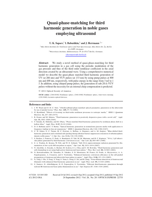
Quasi-phase-matching for third harmonic generation in noble gases employing ultrasoundU. K. Sapaev,1 I. Babushkin,2 and J. Herrmann 1,∗1 Max-Born-Institutefor Nonlinear optics and Fast Spectroscopy, Max-Born-Str. 2a, Berlin D-12489, Germany 2 Weierstrass Institute, Mohrenstrasse 39, D-10117 Berlin, Germany∗ jherrman@mbi-berlin.deAbstract: We study a novel method of quasi-phase-matching for third harmonic generation in a gas cell using the periodic modulation of the gas pressure and thus of the third order nonlinear coefficient in the axial direction created by an ultrasound wave. Using a comprehensive numerical model we describe the quasi-phase matched third harmonic generation of UV (at 266 nm) and VUV pulses (at 133 nm) by using pump pulses at 800 nm and 400 nm, respectively, with pulse energy in the range from 3 mJ to 1 J. In addition, using chirped pump pulses, the generation of sub-20-fs VUV pulses without the necessity for an external chirp compensation is predicted.© 2012 Optical Society of AmericaOCIS codes: (190.0190) Nonlinear optics; (190.4380) Nonlinear optics, four-wave mixing; (230.1040) Acousto-optical devices.References and links1. J. W. Ward and G. H. C. New, “Ultrabroadband phase-matched optical parametric generation in the ultraviolet by use of guided waves,” Phys. Rev. 185, 57–72 (1969). 2. G. Bjorklund, “Effects of focusing on third-order nonlinear processes in isotropic media,“ IEEE J. Quantum Electron. 11, 287–296 (1975). 3. R. Eramo and M. Matera, “Third-harmonic generation in positively dispersive gases with a novel cell,“ Appl. Opt. 33, 1691–1696 (1994). 4. T. Tamaki, K. Midirika, and M. Obara, “Phase-matched third-harmonic generation by nonlinear phase shift in a hollow fiber,“ Appl. Phys. B 67, 59–63 (1998). 5. D. S. Bethune and C. T. Retter, “Optical harmonic generation in nonuniform gaseous media with application to frequency tripling in free-jet expansions,“ IEEE J. Quantum Electron. 23, 1348–1360 (1987). 6. C. W. Siders, N. C. Turner, M. C. Downer, A. Babine, A. Stepanov, and A. M. Sergeev, “Blue-shifted thirdharmonic generation and correlated self-guiding during ultrafast barrier suppression ionization of subatmospheric density noble gases,“ J. Opt. Soc. Am. B 13, 330–336 (1996). 7. S. Backus, J. Peatross, Z. Zeek, A. Rundquist, G. Taft, M. M. Murnane, and H. C. Kapteyn, “16-fs, 1-μ J ultraviolet pulses generated by third-harmonic conversion in air,“ Opt. Lett. 21, 665–667 (1996). 8. S. A. Trushin, K. Kosma, W. Fub, and W. E. Schmid, “Sub-10-fs supercontinuum radiation generated by filamentation of few-cycle 800 nm pulses in argon,“ Opt. Lett. 32, 2432–2434 (2007). 9. N. Akozbek, A. Iwasaki, A. Becker, M. Scalora, S. L. Chin, and C. M. Bowden, “Third-harmonic generation and self-channeling in air using high-power femtosecond laser pulses,“ Phys. Rev. Lett. 89, 143901 (2002). 10. N. Kortsalioudakis, M. Tatarakis, N. Vakakis, S. D. Moustaizis, M. Franco, B. Prade, A. Mysyrowicz, A. A. Papadogiannis, A. Couairon, and S. Tzortzakis, ”Enhanced harmonic conversion efficiency in the self-guided propagation of femtosecond ultraviolet laser pulses in argon,” Appl. Phys. B 80, 211–214 (2005). 11. X. Yang, J. Wu, Y. Peng, Y. Tong, S. Yuan, L. Ding, Z. Xu, and H. Zeng, ”Noncollinear interaction of femtosecond filaments with enhanced third harmonic generation in air,” Appl. Phys. Lett. 95, 111103 (2009). 12. S. Suntsov, D. Abdollahpour, D. G. Papazoglou, S. Tzortzakis, ”Efficient third-harmonic generation through tailored IR femtosecond laser pulse filamentation in air,” Opt. Express 17, 3190–3195 (2009).#173228 - $15.00 USDReceived 24 Jul 2012; revised 6 Sep 2012; accepted 6 Sep 2012; published 19 Sep 2012(C) 2012 OSA24 September 2012 / Vol. 20, No. 20 / OPTICS EXPRESS 2275313. S. Suntsov, D. Abdollahpour, D. G. Papazoglou, S. Tzortzakis, ”Filamentation-induced third-harmonic generation in air via plasma-enhanced third-order susceptibility,” Phys. Rev. A 81, 033817 (2010). 14. Y. Liu, M. Durand, A. Houard, B. Forestier, A. Couairon, A. Mysyrowicz, ”Efficient generation of third harmonic radiation in air filaments: A revisit,” Opt. Commun. 284, 4706–4713 (2011). 15. C. G. Durfee, S. B. Margaret, M. Murnane, and H. C. Kapteyn, “Ultrabroadband phase-matched optical parametric generation in the ultraviolet by use of guided waves,” Opt. Lett. 22, 1565–1567 (1997). 16. P. Tzankov, O. Steinkellner, J. Zheng, M. Mero, W. Freyer, A. Husakou, I. Babushkin, J. Herrmann, and F. Noack, “High-power fifth-harmonic generation of femtosecond pulses in the vacuum ultraviolet using a Ti:sapphire laser,” Opt. Express 15, 6389–6395 (2007). 17. I. V. Babushkin and J. Herrmann, “High energy sub-10 fs pulse generation in vacuum ultraviolet using chirped four wave mixing in hollow waveguides,” Opt. Express 16, 17774–17779 (2008). 18. J. A. Armstrong, N. Bloembergen, J. Ducuing, and P. S. Persham, ”Interactions Between Light Waves in a Nonlinear Dielectric,” Phys. Rev. 127, 1918–1939 (1962). 19. M. M. Fejer, G. A. Magel, D. H. Jundt, and R. L. Byer, ”Quasi-phase-matched second harmonic generation: tuning and tolerances,” IEEE J. Quantum Electron. QE-28, 2631–2654 (1992). 20. A. Paul, R. A. Bartels, R. Tobey, H. Green, S. Weiman, I. P. Christov, M. M. Murnane, H. C. Kapteyn, and S. Backus, “Quasi-phase-matched generation of coherent extreme-ultraviolet light,” Nature (London) 421, 51–54 (2003). 21. S. L. Voronov, I. Kohl, J. B. Madsen, J. Simmons, N. Terry, J. Titensor, Q. Wang, and J. Peatross, “Control of laser high-harmonic generation with counterpropagating light,” Phys. Rev. Lett. 87, 1339021 (2001). 22. X. Zhang, A. L. Lytle, T. Popmintchev, X. Zhou, H. C. Kapteyn, M. M. Murnane, and O. Cohen “Quasi-phasematching and quantum-path control of high-harmonic generation using counterpropagating light,” Nature Phys. 3, 270–275 (2007). 23. J. Herrmann, ”Apparatus and method for amplification and frequency transformation of laser radiation using quasi-phase matching of four-wave mixing,” Patent: DE102009028819A1 (2011). 24. T. G. Leighton, “What is ultrasound?” Prog. in Bioph. and Molec. Biol. 93, 3–83 (2007). 25. A. Holm and H. W. Persson, “Optical diffraction tomography applied to airborne ultrasound,” Ultrasonics 31, 259–265 (1993). 26. J. A. Gallego-Juarez and L. Gaete-Garreton, “Experimental study of nonlineairity in free progressive acoustic waves in air at 20 kHz,” J. De Phys. 40, C8-336–340 (1979). 27. H. Tijdeman, “On the propagation of sound wave in cylindrical tubes,” J. Sound Vibr. 39, 1–13 (1975). 28. E. Rodarte, G. Singh, N. R. Miller, and P. Hrnjak, “Sound attenuation in tubes due to visco-thermal effects,” J. Sound Vibr. 231, 1221–1241 (2000). 29. T. D. Rossing, Handbook of Acoustics (Springer, 2007). 30. M. Iskhakovich, General Acustics (Nauka, Moscow, 1973). 31. L. J. Bond, C. Chiang, and C. M. Fortunko, “Absorption of ultrasonic waves in air at high frequencies (10-20 MHz),” J. Acoust. Soc. Am. 92, 2006–2015 (1992). 32. Z. Song, Y. Qin, G. Zhang, S. Cao, D. Pang, L. Chai, Q. Wanga, Z. Wangb, and Z. Zhang, “Femtosecond pulse propagation in temperature controlled gas-filled hollow fiber,” Opt. Commun. 281, 4109–4113 (2008). 33. M. Mlenjnek, E. M. Wright, and J. V. Moloney, “Femtosecond pulse propagation in argon: A pressure dependence study,” Phys. Rev. Lett. 58, 4903–4910 (1998). 34. A. Couairon, M. Franco, G. Mechain, T. Olivier, B. Prade, and A. Mysyrowicz, “Femtosecond filamentation in air at low pressures: Part I: Theory and numerical simulations,” Opt. Commun. 58, 265–273 (2006). 35. G. P. Agrawal, Nonlinear Fiber Optics (Academic press, USA, 2001). 36. A. Couairon and A. Mysyrowiczb, “Femtosecond filamentation in transparent media,” Phys. Repor. 441, 47-189 (2007).1.IntroductionThird harmonic generation (THG) in gases is a method with one of the simplest setup allowing to generate picosecond and femtosecond pulses in the UV and VUV spectral ranges. Compared with alternative schemes employing solid-state crystals several disadvantages can be avoided by using gases such as low damage threshold, strong dispersion, bandwidth limitations and restrictions of the spectra to the range above 200 nm. For intensities below the ionization threshold THG cannot take place for pump beams focused into a gas cell because the emitted third harmonic (TH) before the focus cancels the one emitted after the focus [1, 2] due to destructive interference. This problem can be avoided by placing the gas cell before or after the focus [1,2], by using a differentially pumped gas cell, a narrow gas jet [3], or hollow waveguides [4, 5]. THG during ultrafast ionization with higher efficiencies has been generated by focusing the#173228 - $15.00 USD Received 24 Jul 2012; revised 6 Sep 2012; accepted 6 Sep 2012; published 19 Sep 2012(C) 2012 OSA24 September 2012 / Vol. 20, No. 20 / OPTICS EXPRESS 22754pump beam inside a chamber with a noble gas with intensities far in excess of that necessary for ionization [6–8]. TH has also been generated during filamentation of femtosecond pulses in air and argon [9–14]. Several papers reported that the efficiency of THG in a filament can be increased by using a second intercepting IR pulse [11–14], which can be explained by the quenching of interference effects [14]. One of the main difficulties, limiting the efficiency in frequency conversion in the above described methods is the problem to realize phase-matching. In UV and VUV pulse generation in hollow waveguides by four-wave mixing phase-matching can be realized using the anomalous dispersion of the fiber [15–17]. However, the small diameter of the capillary limits the pulse energy and leads to more complexity in practical realization. In the case of frequency conversion in solid nonlinear crystals an alternative approach, quasi-phase matching (QPM), is used. It exploits a periodic modulation of the nonlinear susceptibility to correct the linear phase mismatch [18, 19]. For the application in high-order harmonic generation in gas-filled hollow waveguides QPM was demonstrated by using modulated hollow-core waveguides [20] or using counter-propagating light [21, 22]. In this paper, we investigate a novel technic for quasi-phase matching by ultrasound in THG. As presented in Fig. 1 in this scheme a cell filled with a noble gas is excited by a pump pulse and an ultrasound wave which modulates the gas pressure and thus the third order nonlinearity of the gas. For an ultrasound wave-number approximately equal to the module of the linear phase mismatch between the fundamental and the generated TH QPM can be realized, greatly increasing the conversion efficiency. Since the beam diameter is not limited as in hollow waveguides, this method allows the use of very high pump energies with larger diameters for frequency transformation into the VUV. Here we study THG in an argon-filled cell with the pump wavelength at 800 nm for UV and at 400 nm for VUV pulses generation with moderate and high pump energies up to the joule level. Using a comprehensive nonlinear model including the influence of dispersion, diffraction, third-order nonlinearity, ionization as well as the sound loss, we show that the conversion efficiency can be increased as a result of QPM. In particular, we show the possibility that by using pre-chirped femtosecond pump pulses at 400 nm sub-20 fs VUV pulses can be generated. Intriguingly, due to the normal dispersion of the gas the generated VUV pulse at the output is nearly unchirped and thus does not need any additional chirp compensation stage.(a)1.2 1(b)0.3 0.25(c)Ωs [MHz]] β [cm s400 600 800 1000 12000.8 0.6 0.4 0.2 0−10.2 0.15 0.10.05 0λ [nm]0.2 0.4 0.6 0.8Ω [MHz]11.2Fig. 1. QPM for THG using an ultrasound wave. (a) - The basic scheme: the pump with frequency ω is sent into a tube where an ultrasound wave is exited to achieve the QPM. At the output, third harmonic 3ω is observed. (b) - Dependence of the ultrasound frequency Ωs on the pump wavelength λ for THG QPM in argon at 1 atm. (c) - The absorption rate of the ultrasound wave in argon at the normal conditions in dependence on its frequency Ωs .#173228 - $15.00 USDReceived 24 Jul 2012; revised 6 Sep 2012; accepted 6 Sep 2012; published 19 Sep 2012(C) 2012 OSA24 September 2012 / Vol. 20, No. 20 / OPTICS EXPRESS 227552.Quasi-phase matching using ultrasoundQPM is a technic to correct the phase mismatch between interacting waves without matching the phase velocities. QPM in periodically poled nonlinear crystals is realized by a nonlinear structure in which the sign of the nonlinear susceptibility is periodically reversed throughout the medium [18, 19]. However, QPM can also be realized by a periodic modification of the nonlinear coefficient without sign change. A method for QPM in isotropic gases was described in [23], in which an ultrasound transducer in a gas cell excites ultrasound waves which periodically change the pressure or, in other words, the particles number density and therefore the third-order nonlinear susceptibility. The ultrasound wavevector Ks required to achieve QPM of interacting waves in the cell is approximately equal to the phase-mismatch |Δk| due to dispersion of the corresponding waves. In this paper we study in detail THG as a simplest prototypical interaction (see Fig. 1). In this case the phase mismatch is given by Δk = k3ω − 3kω , where kω is the pump wavevector with the frequency ω and k3ω is the TH wavevector with the frequency 3ω . The dependence of the ultrasound frequency Ωs = 2π /Ks on the pump wavelength λ = 2π /ω is shown in Fig. 1(b). As seen for argon QPM for THG with a pump pulse at 800 nm requires an ultrasound frequency of Ωs ≈ 22 kHz and for a pump pulse at 400 nm we find Ωs ≈ 300 kHz. For high intensities the Kerr effect introduces an additional phase shift. Ultrasound waves can be efficiently generated by the application of piezoelectric generators. In liquids, high power ultrasound waves up to tens of MHz are heavily used in many applications in technology, medicine, biology and chemistry [24]. In contrast, in gases typical highpower ultrasound devices rarely exceed ∼ 40 kHz limit. However, some ultrasonic applications such as nondestructive testing require airborn ultrasound from 100 kHz up to 1 MHz. In such applications, the pressure amplitudes p in a pulsed regime can achieve ∼ 10−2 atm inside the area of ∼ 1 cm2 [25]. Even using relatively common airborn high-power ultrasound source with frequency around 20 kHz, higher frequencies can be obtained as harmonics of the fundamental one. In particular, in [26], high power (200 W) cw ultrasound with high pressure level ≈ 160 dB (this corresponds to p ∼ 10−2 atm) was excited in air at atmospheric pressure for a transducer with resonant frequency Ωs = 20 kHz. Due to nonlinearities of generation and propagation, the ultrasound contained higher harmonics; in particular, the contribution of fourth-order harmonic (Ωs = 80 kHz) in this wave was estimated to be up to ≈ 130 dB ( p ≈ 5 × 10⁻⁴ atm). The propagation of sound wave in a tube is relatively well studied [27, 28]. If the viscous effects from the walls can be neglected (the case of “wide tube”), the fundamental sonic mode in a waveguide is homogeneous across the direction transverse to the propagation one. Such mode have also a free-space dispersion and negligible waveguide-induced losses. In the case when viscosity effects becomes important (the case of “narrow tube”), the situation changes. Viscosity leads to the occurring of a boundary layer, with pressure variations decreasing to zero at the walls, and also to additional losses. The role of viscosity is determined by the soΩs called shear wave number s = D 2 ν [27, 28] where D is the tube diameter, ν is the kinematic viscosity. Viscosity effects become important for s ≤ 1. For typical parameters considered in the present article (atmospheric pressure, Ωs = 0.3 MHz) and assuming reasonable tube diameter of ≈ 1 cm ( [25]) we obtain s ∼ 3 × 10³ , that is the approximation of “wide tube” is very well applicable. For the above mentioned parameters, the losses induced by the tube itself are of order of 5 × 10⁻² cm−1 , according the model introduced in [28]. Even in a free space the high frequency ultrasound has noticeable decay, which is in the case of noble gas can be described by the formula [29, 30]:βs =Ω2 s 8π 2 ρ0 c3 s4 κ η + (γ − 1) 3 Cp,(1)where ρ0 is the gas atomic density, cs is the sound speed, κ is the thermal conductivity, η is the#173228 - $15.00 USD Received 24 Jul 2012; revised 6 Sep 2012; accepted 6 Sep 2012; published 19 Sep 2012(C) 2012 OSA24 September 2012 / Vol. 20, No. 20 / OPTICS EXPRESS 22756shear viscosity, γ = Cp /Cv is the rate of the heat capacity at constant pressure (Cp ) and constant volume (Cv ). The dependence of the loss coefficient βs on the ultrasound frequency Ωs for argon is shown in Fig. 1(c). Although the losses given by the classical formula Eq. (1) are underestimated for liquids and multi-atomic gases, Eq. (1) works still reasonably good for noble gases [29–31]. According to the facts mentioned above, the gas pressure can be described in a simple way as a decaying plane wave along the propagation axis z: P(x, y, z) = Po + p(x, y)e−βs z cos(KS z). Here Po is the background pressure and p(x, y) is the ultrasound amplitude, which is constant inside the tube ( x2 + y2 ≡ r < D/2) and zero otherwise (the “wide tube” approximation discussed above) that is, p(x, y) ≡ p = const. The propagation of the pump and TH in the gas-filled tube excited by the ultrasound wave can be described by a comprehensive model taking into account diffraction, dispersion, third-order nonlinearity, gas ionization effects and periodically changing pressure. Using the slowly varying envelope approximation the amplitudes of the pump Aω (x, y, z, t ) and the TH A3ω (x, y, z, t ) as well as the free electron density ρ (x, y, z, t ) in time t and space are given by:∂ Aω 2 iΔkz + Mω Aω = iγω (z) Aω |Aω |2 + 2 |A3ω |2 − Γω + A∗ , (2) ω A3ω e ∂z ∂ A3ω −iΔkz + M3ω A3ω = iγ3ω (z) A3ω |A3ω |2 + 2 |Aω |2 − Γ3ω + A3 /3 , (3) ωe ∂z ∂ρ ρ = (ρo (z) − ρ ) σKω |Aω |2Kω + σK3ω |A3ω | 2K3ω + σω (z) |Aω |2 + σ3ω (z) |A3ω |2 . ∂t Ui (4)Here γm (z) = 3π m2 χ (3) (z) is the third order nonlinear coefficient (m = ω and 3ω for the fundao 2c2 km mental and TH, correspondingly); χ (3) (z) is the third-order nonlinear susceptibility, depending on the pressure P (and hence on z); Δk is the linear phase mismatch for the gas pressure P0 . Mω , M3ω and Γω , Γ3ω are defined as:o ) + νm (z) Mm = −i (km (z) − kmigm (z) ∂ 2 i ∂ ∂2 ∂2 + − + 2 , 2 2 ∂t 2 ∂ t 2km (z) ∂ x ∂y β σm (z) K o (1 + iωm Γm = τc (z)) + m (ρo (z) − ρ ) |Am |2Km −2 , 2 2(5) (6)where νω = 0 and ν3ω (z) = 1/Vω (z) − 1/V3ω (z); Vm (z) and gm (z) are the group velocities and o are the wave numbers for the group velocity dispersions of the interacting pulses; km (z) and km (z-dependent) pressure P and for the background pressure P0 , respectively; σm (z) is the cross section of inverse Bremsstrahlung; τc (z) is the free-carrier collision time; σKm is the ionization cross section, where Km ≡< Ui /h ¯ ωm + 1 > here also Ui is the ionization potential of the gas; βKm is the multiphoton ionization coefficient, which is defined as βKm = Km h ¯ ωm σKm ; ρo (z) is the density of neutral atoms [32, 33]. The coefficients km (z), γm (z), Vm (z), gm (z), σm (z), τc (z), are assumed here to be proportional to the pressure (and thus varying along the z-coordinate) [32–34]. Let us first consider the simplest approximation assuming an un-depleted pump pulse and neglecting diffraction, dispersion, ionization (Γm = 0) and loss, but taking into account the nonlinear self-phase modulation of the pump. Then, the on-axis QPM condition for the ultrasound wave vector Ks is: 2 o 2 (7) KS = Δk + 3γω |Ao ω | − 2γ3ω |Aω |#173228 - $15.00 USDReceived 24 Jul 2012; revised 6 Sep 2012; accepted 6 Sep 2012; published 19 Sep 2012(C) 2012 OSA24 September 2012 / Vol. 20, No. 20 / OPTICS EXPRESS 22757where Ao ω is the field amplitude of the pump at the input. If this condition is fulfilled and the weak non-phase matched contributions are neglected one obtains for the intensity of the third harmonic I3ω : cεo (γ3ω pz)2 o 6 |Aω | . (8) I3ω (z) ≈ 12 Remarkably, I3ω does not depend on the background pressure P0 but only on the ultrasound amplitude p. For a more exact treatment we solved Eqs.(2) − (4) numerically using the split-step method [35] with the fast Fourier transform in time and 2D transverse space dimensions to calculate the linear part of the equations and the fifth-order Runge-Kutta method for the nonlinear one. In the solution of Eq. (4) the fourth-order Runge-Kutta method were used. The results of numerical simulations of Eqs. 2-4 for bandwidth-limited femtosecond and chirped picosecond pump pulses at 800 nm as well as at 400 nm are presented in the Chapter 3. 3. 3.1. Results and their discussion UV pulse generation by using 800 nm pump pulsesFirst, we studied the proposed method for a bandwidth-limited 800 nm Gaussian pump pulse with a duration (FWHM) τω = 700 fs, a radius rω = 0.05 cm and an energy 3 mJ (corresponding to the input intensity Io ≈ 1 TW/cm2 and power Pω ≈ 3.97 GW) with a sound amplitude of p = 0.01 atm. The required ultrasound frequency necessary to fulfill the QPM condition according Eq. (7) is Ωs = 22.24 kHz. For these parameters the self-focusing distance is z f ≈ 11.01 m, the critical power of self-focusing is Pcrit ≈ 3.94 GW and the walk-off length is Lν = τω /ν ≈ 345 m. Therefore one can expect a relatively long propagation distance without beam collapsing, temporal walk-off or formation of a filament [36]. The results for these parameters are presented in Fig. 2. Figure 2(a) shows the results of the analytical formula Eq. (8) (red dashed curve) and of the numerical simulations (red solid curve) for the efficiency of THG defined as η3ω (z) = |A3ω (z, x, y, t )|2 dxdydt / |Aω (z = 0, x, y, t )|2 dxdydt . One can see from the Fig. 2(a) that QPM results in the efficient conversion to the TH at the optimum ultrasound frequency, which is 27 times larger than without ultrasound (green curve). The self-focusing effect is relatively weak as seen from the evolution of pump intensity (blue curve in Fig. 2(b)) and beam radius (red curve in Fig. 2(d)), while that spatial profile of the TH shows a good beam quality (Fig. 2(c)).0.02 0.015 (a) 0.01 0.008 (b) 2 1.8 1.6 1.4 1.2 100 200 z [cm] 1 3 x 10⁻³(c)0.05(d)I [TW/cm 2]η3ω[%]0.01 0.005 0 0r [cm]0.2 0 −0.2 y [mm]0.006 0.004 0.002I ω[TW/cm ][TW/cm 2]22 103ωI3ω0 0.2 0 x [mm] −0.2100 200 z [cm]3000 0−0.050100 200 z [cm]Fig. 2. THG for a 0.7 ps pump pulse at 800 nm with 3 mJ energy. In (a) the conversion efficiency η3ω calculated analytically by Eq. (8) (red-dashed) and numerically (red-solid) in dependence on the propagation distance z (the result in the absence of ultrasound is shown by the green curve); in (b) the evolution of the peak intensity of the pump (blue) and the TH (red); in (c) the spatial intensity profile of the TH at the output and in (d) the change of the radii of the pump (red) and the TH (blue) are presented.Figure 3 shows the results for the case of a bandwidth-limited pump pulse at 800 nm with a high energy of 1 J, a duration of τω = 1 ps (transform-limited), a radius of rω = 0.5 cm and a#173228 - $15.00 USD Received 24 Jul 2012; revised 6 Sep 2012; accepted 6 Sep 2012; published 19 Sep 2012(C) 2012 OSA24 September 2012 / Vol. 20, No. 20 / OPTICS EXPRESS 227580.12 (a) 0.16 5(b)60 50 40 30 20 10 100 200 z [cm] 300 0 (c) 1.50.5(d)I 3ω[TW/cm ]η3ω[%]0.08 0.06 0.04 0.02 0 0 100 200 z [cm] 3004 3 2 1 0 0I ω[TW/cm ][TW/cm 2]22r [cm]0.5 0 −0.5 y [mm]1 0.5 0 0.5 0 −0.5 x [mm]0I3ω−0.50100 200 z [cm]Fig. 3. THG for a 1 ps pump pulse at 800 nm with 1 J energy. The description of (a)-(d) and the curves are analogous as Fig. 2.sound amplitude of p = 0.01 atm. For these parameters one can calculate: Io ≈ 2.4 TW/cm2 , z f ≈ 247 cm, Lν = τω /ν ≈ 487 cm. In this case the power of the pump pulse Pω ≈ 940 GW is much larger than the critical power of self-focusing Pcrit ≈ 3.94 GW, therefore as seen in Fig. 3(d) after a propagation distance of about 2.5 m the pump beam radius significantly decreases and its intensity increases. The efficiency increases up to η3ω ≈ 0.12%, but due to the change of the pump intensity the QPM condition Eq. (7) is violated after this distance. Without ultrasound (green curve) the efficiency is at ∼ 2.5 m 18 times smaller, but after self-focusing distance it increases significantly due to the increase of the pump intensity. 3.2. VUV pulse generation by using 400 nm pump pulsesUsing THG with pump pulses at 400 nm allows frequency transformation into the VUV spectral range at 133 nm. Nowadays, generation of such pump pulses with high energy by second harmonic generation in nonlinear crystals from near-infrared ones is a standard method. Here we study THG with a bandwidth-limited pump pulse at 400 nm with 0.3 mJ energy, duration of τω = 1.4 ps, beam radius of rω = 0.03 cm, pump intensity Io ≈ 1.4 TW/cm2 and sound amplitude of p = 0.01 atm. As one can see from the Fig. 4, the conversion efficiency increases up to the propagation length of about 50 cm. The saturation of THG is caused by the strong self-focusing effect with the formation of a filament. The strong increase of the pump intensity leads to the violation of the optimum QPM condition, which terminates the frequency conversion. Figure 4(b) and 4(d) illustrates the well known dynamics of the formation of a filament after approximately ∼ 50 cm propagation. As seen the combined action of the optical Kerr effect, multiphoton absorption and ionization leads to focusing and defocusing cycles with very small quasi-periodicity [36]. This highly dynamic process leads to aperiodic spikes in the free electron density (Fig. 4.(c)) and recurrent, aperiodic intensity variations (Fig. 4(b)) of the fundamental (blue curve) and the TH (red curve). The resolution in the numerical simulation of Fig. 4. is about 0.2 mm. Next, we investigate TGH with a higher pump energy of 0.1 J with the duration of τω = 1 ps, radius rω = 0.1 cm (Io ≈ 6 TW/cm2 ) and the sound wave amplitude p = 0.01 atm. As can be seen from the Fig. 5. the conversion efficiency of THG up to ≈ 0.02% can be obtained. However, in this case a multifilamentation takes place. It appears because the input peak power (Pω ≈ 93 GW) is much larger than the critical power (Pcrit ≈ 0.9 GW) [36]. 3.3. Sub-20 fs VUV pulse generation by using chirped 400 nm pump pulsesThe method under consideration can be combined with a stretching of the pump pulses to much longer durations. This allows to reduce the peak intensity to a range where deleterious nonlinear effects do not play a role. Using negatively chirped pump pulses the generated chirp of the TH can be compensated by normal dispersive elements. In the simulation shown in Fig. 6 and Fig. 7 we assume a negatively chirped pump pulse with a duration of τω = 1 ps and 0.3 mJ energy#173228 - $15.00 USDReceived 24 Jul 2012; revised 6 Sep 2012; accepted 6 Sep 2012; published 19 Sep 2012(C) 2012 OSA24 September 2012 / Vol. 20, No. 20 / OPTICS EXPRESS 22759x 10 (a) 5 4η3 ω[%]−30.4 (b)100 2x 10 (c)17(d) 0.02[TW/cm 2 ]I ω[TW/cm ] −3 ρ [cm ]21.5 1r [cm]3 2 1 0 0 20 40 z [cm] 600.2500I3ω0.5 0 0 0 0 0 20 40 60−0.02 0 20 40 602040 z [cm]60z [cm]z [cm]Fig. 4. THG for a 1.4 ps pump pulse at 400 nm with 3 mJ energy. In (a) the conversion efficiency calculated analytically by Eq. (8) (dashed) and numerically (solid); in (b) the evolution of the peak intensity of the fundamental (blue) and the TH (red); in (c) the maximum electron density and in (d) the change of radii of the fundamental (red) and the TH (blue) are presented.Fig. 5. THG for a 1 ps pump pulse at 400 nm with 0.1 J energy. In (a) the conversion efficiency calculated analytically by Eq. (8) (dashed) and numerically (solid); in (b) the evolution of the peak intensity of the fundamental (blue) and the TH (red); in (c) the spatial intensity profile of the TH at the output are presented.obtained after phase-modulation from a bandwidth-limited one of 20 fs duration. The beam radius is rω = 0.25 cm, the input intensity is Io ≈ 2.87 TW/cm2 and the sound amplitude is p = 0.01 atm. As one can see, the conversion efficiency is limited to the same level as in the previous example. However, the duration of both pump and TH pulses decrease significantly because of chirp compensation due to propagation in the normal-dispersive argon gas (Fig. 7(a)). The duration of the generated VUV pulse at 133 nm is reduced down to 18 fs (Fig. 7(c)) and its pulse energy is ∼ 3 μ J. This self-compression is caused by a chirp compensation during propagation due to normal dispersion of the gas.x 10 (a)−34η3 ω[%]3 2 1 0 0 10z [cm] 20 300.16 (b) 0.14 0.12 0.1 0.08 0.06 0.04 0.02 0 010z [cm]203080 70 60 50 40 30 20 10 0(c) 0.12 0.1 0.08 0.06 0.04 0.02 0.05 0 x [mm]−0.05 0 −0.05 y [mm][TW/cm 2 ]0.02 0.01r [cm](d)[TW/cm 2 ]I ω[TW/cm 2 ]03ω3ω−0.01 −0.02 0.05 0 z [cm]20IFig. 6. THG for a negatively chirped pump with the energy of 3 mJ. (a) The THG efficiency η3ω in dependence on z; (b) Peak intensity of the fundamental (blue) and the TH (red) pulses versus z; (c) Spatial profile of the TH at the output; (d) Change of radii of the fundamental (red) and TH (blue) with z.#173228 - $15.00 USDReceived 24 Jul 2012; revised 6 Sep 2012; accepted 6 Sep 2012; published 19 Sep 2012(C) 2012 OSA24 September 2012 / Vol. 20, No. 20 / OPTICS EXPRESS 22760I。
力学 mechanics 牛顿力学 Newtonian mechanics 经典力学 classical mechanics 静力学 statics 运动学 kinematics 动力学 dynamics子波 wavelet 次级子波 secondary wavele 驻波 standing wave声强 intensity of sound 声强计 phonometer 声调 intonation音色 musical quality 音调 pitch 声级 sound level声压[强] sound pressure 声源 sound source 声阻抗 acoustic impedance声抗 acoustic reactance 声阻 acoustic resistance 声导纳 acoustic admittance声导 acoustic conductance 声纳 acoustic susceptance 声共振 acoustic resonance声波 sound wave 超声波 supersonic wave 声速 sound velocity次声波 infrasonic wave 亚声速 subsonic speed又称“亚音速”。
超声速 supersonic speed又称“超音速”。
声呐 sonar 共鸣 resonance回波 echo 回声 echo 拍 beat 拍频 beat frequency群速 group velocity 相速 phase velocity 能流 energy flux能流密度 energy flux density 材料力学 mechanics of materials, strength of materials 应力 stress 法向应力 normal stress 剪[切]应力 shear stress单轴应力 uniaxial stress 双轴应力 biaxial stress 拉[伸]应力 tensile stress压[缩]应力 compressive stress 周向应力 circumferential stress纵向应力 longitudinal stress 轴向应力 axial stress弯[曲]应力 bending stress, flexural stress 扭[转]应力 torsional stress局部应力 localized stress 残余应力 residual stress 热应力 thermal stress最大法向应力 maximum normal stress 最小法向应力 minimum normal stress最大剪应力 maximum shear stress 主应力 principal stress主剪应力 principal shear stress 工作应力 working stress 许用应力 allowable stress应力集中 stress concentration 应力集中系数 stress concentration factor应力状态 state of stress 应力分析 stress analysis结构[强度]分析 structured analysis 应变 strain 剪[切]应变 shear strain法向应变 normal strain 拉[伸]应变 tensile strain 压[缩]应变 compressive strain 体积应变 volumetric strain 残余应变 residual strain 热应变 thermal strain最大法向应变 maximum normal strain 主应变 principal strain主剪应变 principal shear strain 名义应变 nominal strain应变状态 state of strain 载荷 load又称“荷载”。
振动方面的专业英语及词汇参见《工程振动名词术语》1 振动信号的时域、频域描述振动过程(Vibration Process)简谐振动(Harmonic Vibration)周期振动(Periodic Vibration)准周期振动(Quasi-periodic Vibration)瞬态过程(Transient Process)随机振动过程(Random Vibration Process)各态历经过程(Ergodic Process)确定性过程(Deterministic Process)振幅(Amplitude)相位(Phase)初相位(Initial Phase)频率(Frequency)角频率(Angular Frequency)周期(Period)复数振动(Complex Vibration)复数振幅(Complex Amplitude)峰值(Peak-value)平均绝对值(Average Absolute Value)有效值(Effective Value,RMS Value)均值(Mean Value,Average Value)傅里叶级数(FS,Fourier Series)傅里叶变换(FT,Fourier Transform)傅里叶逆变换(IFT,Inverse Fourier Transform)离散谱(Discrete Spectrum)连续谱(Continuous Spectrum)傅里叶谱(Fourier Spectrum)线性谱(Linear Spectrum)幅值谱(Amplitude Spectrum)相位谱(Phase Spectrum)均方值(Mean Square Value)方差(Variance)协方差(Covariance)自协方差函数(Auto-covariance Function)互协方差函数(Cross-covariance Function)自相关函数(Auto-correlation Function)互相关函数(Cross-correlation Function)标准偏差(Standard Deviation)相对标准偏差(Relative Standard Deviation)概率(Probability)概率分布(Probability Distribution)高斯概率分布(Gaussian Probability Distribution)概率密度(Probability Density)集合平均(Ensemble Average)时间平均(Time Average)功率谱密度(PSD,Power Spectrum Density)自功率谱密度(Auto-spectral Density)互功率谱密度(Cross-spectral Density)均方根谱密度(RMS Spectral Density)能量谱密度(ESD,Energy Spectrum Density)相干函数(Coherence Function)帕斯瓦尔定理(Parseval''''s Theorem)维纳,辛钦公式(Wiener-Khinchin Formula2 振动系统的固有特性、激励与响应振动系统(Vibration System)激励(Excitation)响应(Response)单自由度系统(Single Degree-Of-Freedom System) 多自由度系统(Multi-Degree-Of- Freedom System) 离散化系统(Discrete System)连续体系统(Continuous System)刚度系数(Stiffness Coefficient)自由振动(Free Vibration)自由响应(Free Response)强迫振动(Forced Vibration)强迫响应(Forced Response)初始条件(Initial Condition)固有频率(Natural Frequency)阻尼比(Damping Ratio) 衰减指数(Damping Exponent)阻尼固有频率(Damped Natural Frequency)对数减幅系数(Logarithmic Decrement)主频率(Principal Frequency)无阻尼模态频率(Undamped Modal Frequency)模态(Mode)主振动(Principal Vibration)振型(Mode Shape)振型矢量(Vector Of Mode Shape)模态矢量(Modal Vector)正交性(Orthogonality)展开定理(Expansion Theorem)主质量(Principal Mass)模态质量(Modal Mass)主刚度(Principal Stiffness)模态刚度(Modal Stiffness)正则化(Normalization)振型矩阵(Matrix Of Modal Shape)模态矩阵(Modal Matrix)主坐标(Principal Coordinates)模态坐标(Modal Coordinates)模态分析(Modal Analysis)模态阻尼比(Modal Damping Ratio)频响函数(Frequency Response Function)幅频特性(Amplitude-frequency Characteristics)相频特性(Phase frequency Characteristics)共振(Resonance)半功率点(Half power Points)波德图(Bodé Plot)动力放大系数(Dynamical Magnification Factor)单位脉冲(Unit Impulse)冲激响应函数(Impulse Response Function)杜哈美积分(Duhamel’s Integral)卷积积分(Convolution Integral)卷积定理(Convolution Theorem)特征矩阵(Characteristic Matrix)阻抗矩阵(Impedance Matrix)频响函数矩阵(Matrix Of Frequency Response Function)导纳矩阵(Mobility Matrix)冲击响应谱(Shock Response Spectrum)冲击激励(Shock Excitation)冲击响应(Shock Response)冲击初始响应谱(Initial Shock Response Spectrum)冲击剩余响应谱(Residual Shock Response Spectrum) 冲击最大响应谱(Maximum Shock Response Spectrum)冲击响应谱分析(Shock Response Spectrum Analysis 3 模态试验分析模态试验(Modal Testing)机械阻抗(Mechanical Impedance)位移阻抗(Displacement Impedance)速度阻抗(Velocity Impedance)加速度阻抗(Acceleration Impedance)机械导纳(Mechanical Mobility)位移导纳(Displacement Mobility)速度导纳(Velocity Mobility)加速度导纳(Acceleration Mobility)驱动点导纳(Driving Point Mobility)跨点导纳(Cross Mobility)传递函数(Transfer Function)拉普拉斯变换(Laplace Transform)传递函数矩阵(Matrix Of Transfer Function)频响函数(FRF,Frequency Response Function)频响函数矩阵(Matrix Of FRF)实模态(Normal Mode)复模态(Complex Mode)模态参数(Modal Parameter)模态频率(Modal Frequency)模态阻尼比(Modal Damping Ratio)模态振型(Modal Shape)模态质量(Modal Mass)模态刚度(Modal Stiffness)模态阻力系数(Modal Damping Coefficient)模态阻抗(Modal Impedance)模态导纳(Modal Mobility)模态损耗因子(Modal Loss Factor)比例粘性阻尼(Proportional Viscous Damping)非比例粘性阻尼(Non-proportional Viscous Damping) 结构阻尼(Structural Damping,Hysteretic Damping) 复频率(Complex Frequency)复振型(Complex Modal Shape)留数(Residue)极点(Pole)零点(Zero)复留数(Complex Residue)随机激励(Random Excitation)伪随机激励(Pseudo Random Excitation)猝发随机激励(Burst Random Excitation)稳态正弦激励(Steady State Sine Excitation)正弦扫描激励(Sweeping Sine Excitation)锤击激励(Impact Excitation)频响函数的H1 估计(FRF Estimate by H1)频响函数的H2 估计(FRF Estimate by H2)频响函数的H3 估计(FRF Estimate by H3)单模态曲线拟合法(Single-mode Curve Fitting Method) 多模态曲线拟合法(Multi-mode Curve Fitting Method) 模态圆(Mode Circle)剩余模态(Residual Mode)幅频峰值法(Peak Value Method)实频-虚频峰值法(Peak Real/Imaginary Method)圆拟合法(Circle Fitting Method)加权最小二乘拟合法(Weighting Least Squares Fitting method)复指数拟合法(Complex Exponential Fitting method) 1.2 振动测试的名词术语1 传感器测量系统传感器测量系统(Transducer Measuring System)传感器(Transducer)振动传感器(Vibration Transducer)机械接收(Mechanical Reception)机电变换(Electro-mechanical Conversion)测量电路(Measuring Circuit)惯性式传感器(Inertial Transducer,Seismic (地震?)Transducer)相对式传感器(Relative Transducer)电感式传感器(Inductive Transducer)应变式传感器(Strain Gauge Transducer)电动力传感器(Electro-dynamic Transducer)压电式传感器(Piezoelectric Transducer)压阻式传感器(Piezoresistive Transducer)电涡流式传感器(Eddy Current Transducer)伺服式传感器(Servo Transducer)灵敏度(Sensitivity)复数灵敏度(Complex Sensitivity)分辨率(Resolution)频率范围(Frequency Range)线性范围(Linear Range)频率上限(Upper Limit Frequency)频率下限(Lower Limit Frequency)静态响应(Static Response)零频率响应(Zero Frequency Response)动态范围(Dynamic Range)幅值上限(Upper Limit Amplitude)幅值下限(Lower Limit Amplitude)最大可测振级(Max.Detectable Vibration Level)最小可测振级(Min.Detectable Vibration Level)信噪比(S/N Ratio)振动诺模图(Vibration Nomogram)相移(Phase Shift)波形畸变(Wave-shape Distortion) 比例相移(Proportional Phase Shift)惯性传感器的稳态响应(Steady Response Of Inertial Transducer)惯性传感器的稳击响应(Shock Response Of Inertial Transducer)位移计型的频响特性(Frequency Response Characteristics Vibrometer)加速度计型的频响特性(Frequency Response Characteristics Accelerometer)幅频特性曲线(Amplitude-frequency Curve)相频特性曲线(Phase-frequency Curve)固定安装共振频率(Mounted Resonance Frequency) 安装刚度(Mounted Stiffness)有限高频效应(Effect Of Limited High Frequency)有限低频效应(Effect Of Limited Low Frequency)电动式变换(Electro-dynamic Conversion)磁感应强度(Magnetic Induction,Magnetic Flux Density)磁通(Magnetic Flux)磁隙(Magnetic Gap)电磁力(Electro-magnetic Force)相对式速度传感器(Relative Velocity Transducer)惯性式速度传感器(Inertial Velocity Transducer)速度灵敏度(Velocity Sensitivity)电涡流阻尼(Eddy-current Damping)无源微(积)分电路(Passive Differential (Integrate) Circuit)有源微(积)分电路(Active Differential (Integrate) Circuit)运算放大器(Operational Amplifier)时间常数(Time Constant)比例运算(Scaling)积分运算(Integration)微分运算(Differentiation)高通滤波电路(High-pass Filter Circuit)低通滤波电路(Low-pass Filter Circuit)截止频率(Cut-off Frequency)压电效应(Piezoelectric Effect)压电陶瓷(Piezoelectric Ceramic)压电常数(Piezoelectric Constant)极化(Polarization)压电式加速度传感器(Piezoelectric Acceleration Transducer)中心压缩式(Center Compression Accelerometer)三角剪切式(Delta Shear Accelerometer)压电方程(Piezoelectric Equation)压电石英(Piezoelectric Quartz)电荷等效电路(Charge Equivalent Circuit)电压等效电路(Voltage Equivalent Circuit)电荷灵敏度(Charge Sensitivity)电压灵敏度(Voltage Sensitivity)电荷放大器(Charge Amplifier)适调放大环节(Conditional Amplifier Section)归一化(Uniformization)电荷放大器增益(Gain Of Charge Amplifier)测量系统灵敏度(Sensitivity Of Measuring System) 底部应变灵敏度(Base Strain Sensitivity)横向灵敏度(Transverse Sensitivity)地回路(Ground Loop)力传感器(Force Transducer)力传感器灵敏度(Sensitivity Of Force Transducer)电涡流(Eddy Current)前置器(Proximitor)间隙-电压曲线(Voltage vs Gap Curve)间隙-电压灵敏度(Voltage vs Gap Sensitivity)压阻效应(Piezoresistive Effect)轴向压阻系数(Axial Piezoresistive Coefficient)横向压阻系数(Transverse Piezoresistive Coefficient) 压阻常数(Piezoresistive Constant)单晶硅(Monocrystalline Silicon)应变灵敏度(Strain Sensitivity)固态压阻式加速度传感器(Solid State PiezoresistiveAccelerometer)体型压阻式加速度传感器(Bulk Type Piezoresistive Accelerometer)力平衡式传感器(Force Balance Transducer)电动力常数(Electro-dynamic Constant)机电耦合系统(Electro-mechanical Coupling System) 2 检测仪表、激励设备及校准装置时间基准信号(Time Base Signal)李萨茹图(Lissojous Curve)数字频率计(Digital Frequency Meter)便携式测振表(Portable Vibrometer)有效值电压表(RMS Value Voltmeter)峰值电压表(Peak-value Voltmeter)平均绝对值检波电路(Average Absolute Value Detector) 峰值检波电路(Peak-value Detector)准有效值检波电路(Quasi RMS Value Detector)真有效值检波电路(True RMS Value Detector)直流数字电压表(DVM,DC Digital Voltmeter)数字式测振表(Digital Vibrometer)A/D 转换器(A/D Converter)D/A 转换器(D/A Converter)相位计(Phase Meter)电子记录仪(Lever Recorder)光线示波器(Oscillograph)振子(Galvonometer)磁带记录仪(Magnetic Tape Recorder)DR 方式(直接记录式) (Direct Recorder)FM 方式(频率调制式) (Frequency Modulation)失真度(Distortion)机械式激振器(Mechanical Exciter)机械式振动台(Mechanical Shaker)离心式激振器(Centrifugal Exciter)电动力式振动台(Electro-dynamic Shaker)电动力式激振器(Electro-dynamic Exciter)液压式振动台(Hydraulic Shaker)液压式激振器(Hydraulic Exciter)电液放大器(Electro-hydraulic Amplifier)磁吸式激振器(Magnetic Pulling Exciter)涡流式激振器(Eddy Current Exciter)压电激振片(Piezoelectric Exciting Elements)冲击力锤(Impact Hammer)冲击试验台(Shock Testing Machine)激振控制技术(Excitation Control Technique)波形再现(Wave Reproduction)压缩技术(Compression Technique)均衡技术(Equalization Technique)交越频率(Crossover Frequency)综合技术(Synthesis Technique)校准(Calibration)分部校准(Calibration for Components in system)系统校准(Calibration for Over-all System)模拟传感器(Simulated Transducer)静态校准(Static Calibration)简谐激励校准(Harmonic Excitation Calibration)绝对校准(Absolute Calibration)相对校准(Relative Calibration)比较校准(Comparison Calibration)标准振动台(Standard Vibration Exciter)读数显微镜法(Microscope-streak Method)?光栅板法(Ronchi Ruling Method)光学干涉条纹计数法(Optical Interferometer Fringe Counting Method)光学干涉条纹消失法(Optical Interferometer Fringe Disappearance Method)背靠背安装(Back-to-back Mounting)互易校准法(Reciprocity Calibration)共振梁(Resonant Bar)冲击校准(Impact Exciting Calibration)摆锤冲击校准(Ballistic Pendulum Calibration)落锤冲击校准(Drop Test Calibration)振动和冲击标准(Vibration and Shock Standard) 迈克尔逊干涉仪(Michelson Interferometer)摩尔干涉图象(Moire Fringe)参考传感器(Reference Transducer)3 频率分析及数字信号处理带通滤波器(Band-pass Filter)半功率带宽(Half-power Bandwidth)3 dB 带宽(3 dB Bandwidth)等效噪声带宽(Effective Noise Bandwidth)恒带宽(Constant Bandwidth)恒百分比带宽(Constant Percentage Bandwidth)1/N 倍频程滤波器(1/N Octave Filter)形状因子(Shape Factor)截止频率(Cut-off Frequency)中心频率(Centre Frequency)模拟滤波器(Analog Filter)数字滤波器(Digital Filter)跟踪滤波器(Tracking Filter)外差式频率分析仪(Heterodyne Frequency Analyzer) 逐级式频率分析仪(Stepped Frequency Analyzer)扫描式频率分析仪(Sweeping Filter Analyzer)混频器(Mixer)RC 平均(RC Averaging)平均时间(Averaging Time)扫描速度(Sweeping Speed)滤波器响应时间(Filter Response Time)离散傅里叶变换(DFT,Discrete Fourier Transform) 快速傅里叶变换(FFT,Fast Fourier Transform)抽样频率(Sampling Frequency)抽样间隔(Sampling Interval)抽样定理(Sampling Theorem)抗混滤波(Anti-aliasing Filter)泄漏(Leakage)加窗(Windowing)窗函数(Window Function)截断(Truncation)频率混淆(Frequency Aliasing)乃奎斯特频率(Nyquist Frequency)矩形窗(Rectangular Window)汉宁窗(Hanning Window)凯塞-贝塞尔窗(Kaiser-Bessel Window)平顶窗(Flat-top Window)平均(Averaging)线性平均(Linear Averaging)指数平均(Exponential Averaging)峰值保持平均(Peak-hold Averaging)时域平均(Time-domain Averaging)谱平均(Spectrum Averaging)重叠平均(Overlap Averaging)栅栏效应(Picket Fence Effect)吉卜斯效应(Gibbs Effect)基带频谱分析(Base-band Spectral Analysis)选带频谱分析(Band Selectable Spectral Analysis) 细化(Zoom)数字移频(Digital Frequency Shift)抽样率缩减(Sampling Rate Reduction)功率谱估计(Power Spectrum Estimate)相关函数估计(Correlation Estimate)频响函数估计(Frequency Response Function Estimate)相干函数估计(Coherence Function Estimate)冲激响应函数估计(Impulse Response Function Estimate)倒频谱(Cepstrum)功率倒频谱(Power Cepstrum)幅值倒频谱(Amplitude Cepstrum)倒频率(Quefrency)4 旋转机械的振动测试及状态监测状态监测(Condition Monitoring)故障诊断(Fault Diagnosis)转子(Rotor)转手支承系统(Rotor-Support System)振动故障(Vibration Fault)轴振动(Shaft Vibration)径向振动(Radial Vibration)基频振动(Fundamental Frequency Vibration)基频检测(Fundamental Frequency Component Detecting)键相信号(Key-phase Signal)正峰相位(+Peak Phase)高点(High Spot)光电传感器(Optical Transducer)同相分量(In-phase Component)正交分量(Quadrature Component)跟踪滤波(Tracking Filter)波德图(Bode Plot)极坐标图(Polar Plot)临界转速(Critical Speed)不平衡响应(Unbalance Response)残余振幅(Residual Amplitude)方位角(Attitude Angle)轴心轨迹(Shaft Centerline Orbit)正进动(Forward Precession)同步正进动(Synchronous Forward Precession)反进动(Backward Precession)正向涡动(Forward Whirl)反向涡动(Backward Whirl)油膜涡动(Oil Whirl)油膜振荡(Oil Whip)轴心平均位置(Average Shaft Centerline Position) 复合探头(Dual Probe)振摆信号(Runout Signal)电学振摆(Electrical Runout)机械振摆(Mechanical Runout)慢滚动向量(Slow Roll Vector)振摆补偿(Runout Compensation)故障频率特征(Frequency Characteristics Of Fault) 重力临界(Gravity Critical)对中(Alignment)双刚度转子(Dual Stiffness Rotor)啮合频率(Gear-mesh Frequency)间入简谐分量(Interharmonic Component)边带振动(Side-band Vibration)三维频谱图(Three Dimensional Spectral Plot)瀑布图(Waterfall Plot)级联图(Cascade Plot)阶次跟踪(Order Tracking)阶次跟踪倍乘器(Order Tracking Multiplier)监测系统(Monitoring System)适调放大器(Conditional Amplifier)趋势分析(Trend Analysis)倒频谱分析(Cepstrum Analysis)直方图(Histogram)确认矩阵(Confirmation Matrix)通频幅值(Over-all Amplitude)幅值谱(Amplitude Spectrum)相位谱(Phase Spectrum)报警限(Alarm Level)往复式制冷压缩机(Reciprocating refrigeration compressor)润滑系统(lubrication system)离心油泵(centrifugal oil pump)。
二阶级联非线性光学效应中的最佳耦合函数安斓;朱海飞;徐永刚;林钱兰;李永放【摘要】为了获得非线性光学晶体中最大的能量转化,研究了由两个二阶非线性效应实现三次谐波产生的物理过程.基于能量守恒条件,得到在能量最大转换条件下两个耦合系数比所具有的函数形式和特点.利用数值计算验证了耦合函数比为t =tanh(z),t=arctan(tz)/1.55以及t=(1-sech(1.8z))时均可获得三次谐波的最大能量输出.%The physical process of the third-harmonic generation (THG)produced by cascaded second-order nonlinear optical effects is investigated in order to obtain the maximum energy conversion in nonlinear optical crystals.Based on the energy conservation condition,the functional form and characteristics of two coupling parametric ratios are obtained under the maximum THG conversion efficiency.When coupling parametric ra-tios has the form thatt=tanh(z),t=arctan(4z)/1.55,t=(1-sech(1.8z)),the maximum energy output of third harmonic can be obtained.【期刊名称】《陕西师范大学学报(自然科学版)》【年(卷),期】2014(000)005【总页数】4页(P43-46)【关键词】非线性级联过程;三次谐波;能量转移【作者】安斓;朱海飞;徐永刚;林钱兰;李永放【作者单位】陕西师范大学物理学与信息技术学院,陕西西安 710119;陕西师范大学物理学与信息技术学院,陕西西安 710119;陕西师范大学物理学与信息技术学院,陕西西安 710119;陕西师范大学物理学与信息技术学院,陕西西安710119;陕西师范大学物理学与信息技术学院,陕西西安 710119【正文语种】中文【中图分类】O437在光学参量频率转换的效率中,三阶效应通常小于二阶效应.为了提高转换效率,人们可以利用级联的二阶非线性效应代替三阶效应.例如:利用对基频光场的倍频后再与基频光耦合获得和频ω+2ω=3ω产生三次谐波,这便是两个二阶非线性光效应的级联过程.利用这种方法代替利用三阶非线性效应直接产生三次谐波过程是近些年来人们十分关注的研究问题,称为多级参量过程[1].在非线性光学频率转化过程中,满足相位匹配是提高能量转换的重要问题,由于准相位匹配(QPM)技术的广泛使用,即在晶体中制备具有周期或非周期性结构来调制晶体的特性(本质上是利用了光学超晶格方法构建光学晶体),有效地解决相位匹配和设计极化参数的问题,从而实现宽带频率的转换问题[2-5]、二次谐波(SHG)的产生[6-8]、差频产生[9]和参量放大[7-10]过程中操纵短脉冲等问题.由此可见利用超晶格技术实现准相位匹配、设计合理有效的极化参数是实现高效频率转换的重要手段.在级联二阶非线性光学效应中,由于同时有两个二阶效应存在,即存在两个耦合系数.在一个晶体中两个耦合系数应该满足何种关系可以实现能量的最大转换,这无疑是一个重要的问题.在这方面文献[11]研究了利用二阶级联非线性耦合效应实现三次谐波最大转换效率的最佳耦合系数比为0.885 8.本文基于能量守恒条件拓展文献[11]的研究结果,在能量最大转换条件下获得一组耦合系数比的函数,描述了函数形式与特点.利用数值计算验证这些函数均可获得三次谐波的最大能量输出.研究结果为利用光学超晶格方法设计合适光学晶体提供的参考.1 耦合波方程在非线性光学的研究过程中,通常假设较强基频泵浦光场的能量是不损耗的,这样可将非线性方程组转化为线性方程组加以求解.但考虑到能量守恒和在较高转换效率的情况下,基频泵浦光场的能量会转换为其他频率场辐射,因此基频光场的能量变化不能忽略.由此,描述这样过程的方程便成为非线性方程,而描述级联二阶非线性光学效应便是一组非线性方程.由级联二阶非线性效应获得三次谐波的耦合波方程组可以写为[11]其中Ai=Ei(i=1,2,3),Δk1=k2ω-2kω-G1,Δk2=k3ω-k2ω-kω -G2,α=(f1deff/c)[ω2/(n2)]1/2,β=(f2,deff/c)[ω1ω2ω3/(n1n2n3)]1/2,分别表示产生与二次谐波和三次谐波相关的耦合系数.c表示真空中的光速,deff是有效非线性系数.fa和Ga是傅里叶系数和结构所对应倒格矢.Ai、ωi和ni(i=1,2,3)分别是基频、二次谐波和三次谐波的光场振幅、频率和折射率.方程(1)所描述的级联二阶非线性光学效应中的三次谐波产生过程如图1所示.它包含了两个和频和三个差频过程.方程只包含二阶非线性效应,但不包括ω+ω+ω=3ω的三阶非线性过程.图1 三次谐波产生的级联二阶非线性光学效应关联图Fig.1 The schematic diagram of the third-harmonic produced by cascaded second-order nonlinear optical effects.根据方程组(1)可以证明,基频、二次谐波和三次谐波之间满足能量守恒关系其中假设初始入射的基频光场能量|A1|2=1.在方程(1)中要实现相位匹配,关键是要建立一种超晶格结构以满足QPM技术要求,它提供一个倒格矢以补偿由于晶体色散导致的相位匹配作用.倒格矢可以使光学参量过程在材料中满足相位匹配.即满足关系:Δk1=k2ω-2kω-G1和Δk2=k3ω-k2ω-kω-G2=0,如图2所示.图2 二次谐波和三次谐波过程中的相位匹配关系Fig.2 The phase matching relationship in the secondharmonic(SH)and the third-harmonic(TH)generation process为了简化方程,令y1=A1,y2=-i A2,A2=i y2,y3=-A3,t=α/β,代入方程(1)中可以得到满足相位匹配条件的简化方程组同时能量守恒关系改写为为了求解(3)式中两个耦合系数比t为实现三次谐波最大能量转换应满足的条件,令y3=uy1,其微分关系式为dy3=y1du+udy1.将其带入方程(3)后可以得到方程对方程(4)两边积分后,并根据变换关系:arctan(θ)±arctan(φ)=arctan 可得简化后的结果为其中g=t/2.在频率转换过程中,当入射泵浦光场和中间产生的二次谐波光场的能量通过和频过程全部转换为三次谐波时,可以得到最大三次谐波能量转换.即满足y1=y2=0时,y3达到最大值.根据,可以得到=1/3.因此在y3最大值时有:uy1=y3=1.将其带入方程(5)并考虑在y1=0时,u→0.这样对(5)式取极限可以得到(6)式是满足能量守恒条件下,并考虑了最大能量转换时耦合系数比应满足的关系式,其中θ=arctan根据三角函数关系,可以确定θ角与g的关系为:tanθ=,由此可以得到cosθ=g.对方程(6)式两边取对数可得到:θ=ln3.再依据上面的三角函数关系最后可以得到:根据这一关系[11],可以得到一个重要参数,即当t=0.885 8时可以实现三次谐波的最大转换,而另外一个t=2.0则不能够实现三次谐波的最大转换.但(7)式是一个超越方程,应该有一系列函数满足这一关系.而获得关于g的函数表示对于利用光学超晶格设计产生级联二阶非线性光学效应的光学晶体具有重要意义.2 非线性耦合系数关系与能量完全转移2.1 耦合系数比t=α/β为常数时的能量转换图3给出三角函数y=cos和直线y=t/2的演化关系.显然只有在交点处两个函数相等.由于余弦函数在t≤0.5之前为快速振荡,其平均值为零.只有达到稳定后的交点才是有价值的.余弦函数接近稳定值后与直线有两个交点,它们分别为t=0.885 8和t=2.0.图3 余弦函数y=cos和y=t/2直线函数的演化关系Fig.3 The relationship between y=cosand y=t/2将两个数值带入到方程(3)进行数值计算发现只有当t=0.885 8时可以实现光场能量的完全转换.这说明两个耦合系数均为常数,其中α表示的是基频光场与二次谐波的产生有关,β是与三次谐波的产生相关联.在晶体中它们在所有位置满足α<β的条件说明,只有与三次谐波产生相关的耦合过程大于二次谐波产生过程方可实现能量的最大转换,如图4结果所示.而第二值t=2.0,在晶体中始终满足关系α>β,与前一结果相反,不能够获得完全能量转换.这种关系类似于在三能级系统中利用受激拉曼绝热转移技术实现将基态的粒子完全转移到终态之中对耦合场的要求[12-13].图4 耦合系数比为t=0.885 8,级联二阶非线性过程中基频光、二次谐波和三次谐波的能量转换关系Fig.4 The energy conversion process between fundamental frequency light field and the SH and TH for t=0.885 82.2 耦合系数t=α/β比为晶体长度的函数时的能量转换从方程(7)左边的余弦函数可以看到,只有t/2≤1时函数是有意义的.而在t<0.2之前时函数呈震荡形式,它的平均值为零.而当t/2→1时余弦函数趋近于1.由此可以知道,若方程(7)右边的函数也满足初始时t/2→0,之后满足t/2→1的特征时便可使方程(7)两边成立.依据这一特点,我们选取如图5中所示的3个函数,它们具有相同的特征,即初始为零,之后逐渐趋近于1.利用3个比值函数,对方程(3)做数值计算便可实现三次谐波的最大能量转换,如图6所示.这些耦合系数比函数是在系统满足能量守恒条件和在基频光、二次谐波光场能量都转换为三次谐波时获得最大能量输出的结果.因此由方程(7)所得到的3个耦合系数比函数均满足上述条件,因此都可实现最佳二阶级联非线性光频转换.这一结果对于设计非线性光学晶体中的极化参数具有一定的意义,这也是本文主要结果.图5 不同耦合系数比函数的演化关系Fig.5 The relationship of different coupling coefficients ratio function3 结论依据级联二阶非线性光学效应研究了三次谐波产生过程中的能量最大转换问题.一个基频光场作用到非线性光学晶体后,首先通过一个二阶非线性效应产生二次谐波,然后由基频光场与二次谐波通过和频过程再产生三次谐波.这其中经历了两个二阶非线性光学效应,因此存在着两个耦合系数α和β.利用能量守恒条件,在满足相位匹配条件下,研究了当两个耦合系数比满足方程(7)的解便可实现将基频光场的能量完全转换为三次谐波能量.从3个耦合系数比t的特征以及耦合波方程可以看到,在初始阶段α=0而β=1,这说明在二次谐波与基频光之间的耦合要先于二次谐波的过程;随着α的逐渐增加,二次谐波逐渐产生,而产生后的二次谐波很快就和基频光场耦合产生三次谐波.这一物理过程与三能级系统中的受激拉曼绝热通道转移技术完全一样.由此可见,这一物理过程与原子分子中的粒子布居完全转移相类似.文中所得结果对于研究、设计级联二阶非线性频率转换器件具有一定参考价值.图6 不同耦合系数比情况下的级联二阶非线性过程中基频光、二次谐波和三次谐波的能量转换关系Fig.6 The energy conversion relationship between fundamental frequency light field and the SH and TH for different coupling coefficients ratioa.耦合系数比为α/β=tanh(z) b.耦合系数比为α/β=(1-sech(1.8z)) c.耦合系数比为α/β=acrtan(4z)/1.55参考文献:[1]Saltiel S M,Sukhorukov A A,Kivshar Y S.Multistep parametric processes in nonlinear[J].Progress in Optics,2005,47:1-73.[2]Bortz M L,Fujimura M,Fejer M M.Increased acceptance bandwidth for quasi-phasematched second harmonic generation inLiNbO3waveguides[J].Electronics Letters,1994,30(1):34-35.[3]Mizuuchi K,Yamamoto K,Kato M,et al.Broadening of the phase-matching bandwidth in quasi-phasematched second-harmonic generation [J].IEEE Journal of Quantum Electronics,1994,30:1596-1604.[4]Guo Hongchen,Tang Singhai,Qin Yiqiang,et al.Nonlinear frequency conversion with quasi-phase-mismatch effect[J].Physical Review E,2005,71:066615.[5]Baudrier-Raybaut M,Haidar R,Kupecek P,et al.Random quasi phase matching in bulk polycrystalline isotropic nonlinear materials[J].Nature,2004,432:374-376.[6]Arbore M A,Galvanauskas A,Harter D,et al.Engi-neerable compression of ultrashort pulses by use of second-harmonic generation in chirped-period-poled lithium niobate[J].Optics Letters,1997,22:1341-1343.[7]Imeshev G,Arbore M A,Fejer M M,et al.Ultrashortpulse second-harmonic generation with longitudinally nonuniform quasi-phase-matching gratings:pulse compression and shaping[J].Journal of the Optical Society of America B,2000,17:304-318.[8]Hum D S,Fejer M M.Quasi-phasematching[J].Comptes Rendus Physique,2007,8:180-198.[9]Imeshev G,Fejer M,Galvanauskas A,et al.Pulse shaping by difference-frequency mixing with quasi-phasematching gratings[J].Journal of the Optical Society of America B,2001,18(4):534-539. [10]Charbonneau-Lefort M,Afeyan B,Fejer M M.Optical parametric amplifiers using chirped quasiphase-matching gratings I:Practical design formulas[J].Journal of the Optical Society of America B,2008,25(4):463-480.[11]Zhang Chao,Zhu Yongyuan,Yang Suxia,et al.Crucial effects of coupling coefficients on quasi-phasematched harmonic generation in an optical superlattice[J].Optics Letters,2000,25:436-438.[12]Bergmann K,Theuer H,Shore B W,Coherent population transfer among quantum states of atoms and molecules[J].Reviews of Modern Physics,1998,70(3):1003-1025.[13]Kuklinski J R,Gaubatz U,Hioe F T,et al.Adiabatic population transfer in a three-level system driven by delayed laser pulses[J].Physical Review A,1989,40:6741-6744.。
Journal of Nonlinear Optical Physics &Materials Vol.23,No.1(2014)1450013(10pages)cWorld Scientific Publishing Company DOI:10.1142/S0218863514500131Quasi-phase-matching of laser harmonics usingvariable multi-jet plasmasR.A.Ganeev ∗,†,§,M.Suzuki ∗,P.V.Redkin ‡and H.Kuroda ∗∗Ophthalmologyand Advanced Laser Medical Center,Saitama Medical University,Saitama 350-0495,Japan†VoronezhState University,Voronezh 394006,Russia‡SamarkandState University,Samarkand 140104,Uzbekistan§rashid ganeev@mail.ru Received 9February 2014In this paper,we demonstrate the enhancement of high-order harmonics induced by the quasi-phase-matching (QPM)in different spectral ranges.The tuning of QPM harmonics was accomplished by changing the sizes of multiple plasma jets.The 40×and 15×enhancement factors for the QPM harmonics were achieved in the silver and manganese multiple-jet plasmas for the 35th and 55th harmonics.Keywords :Laser plasma;high-order harmonics.1.IntroductionCreation of the coherent extreme ultraviolet (XUV)radiation sources through the harmonic generation by different means and using various media (gases,surfaces,plasmas)is a well elaborated technique,which however shows the low efficiency of those sources.The relatively high efficiencies of generating harmonics obtained using several plasma formations,resonance-induced enhancement of individual har-monics,efficient harmonic generation from the plasma plumes containing clusters of different materials,and other features have demonstrated the attractiveness of the high-order harmonic generation (HHG)in the laser-produced plasmas.The intensity of plasma harmonics has been increased by proper optimization of the (a)intensity of the heating pulse,(b)delay between heating pulse and driving fem-tosecond pulse,(c)focal position of the driving radiation in the plasma plume,(d)pulse duration of the heating radiation,(e)chirp of the driving radiation,(f)use of the clustered targets,and (g)plasma characteristics.1J . N o n l i n e a r O p t i c . P h y s . M a t . 2014.23. D o w n l o a d e d f r o m w w w .w o r l d s c i e n t i f i c .c o m b y Z H E J I A N G U N I V E R S I T Y o n 08/07/14. F o r p e r s o n a l u s e o n l y .R.A.Ganeev et al.The majority of plasma harmonic studies were carried out using the short length plasma plumes (≤0.5mm).In the meantime,one could expect that the applica-tion of longer plasmas would further enhance the conversion efficiency due to the quadratic dependence of the nonlinear optical response of the medium on the length of the laser–matter interaction.To create an extended ablated area on the tar-get surface,one has to carefully choose the conditions of plasma formation.The absorption of extended plasma can prevent the enhancement of harmonic yield.The presence of free electrons and excited ions in the extended plasma plumes can cause the growth of the phase mismatch between the driving and harmonic waves during propagation of the laser pulse through the medium.One of the ways to overcome this obstacle is a division of extended plasma onto a group of small jets to create a condition for the quasi-phase-matching (QPM)for the plasma harmon-ics.The concept of the QPM for the HHG in the multi-jet media has previously been demonstrated using the gaseous media,2–4while various peculiarities of this technique have been reported in Refs.5–11.The attractiveness of the application of the QPM for the amendment of plasma HHG is related with the adjustment of the electron concentration (N e )in the periodically modulated plasma plume by appropriate excitation of the ablating target.The variation of N e allows the manipulation of the coherence length of har-monics in different spectral ranges.The adjustment of N e could be easily accom-plished during harmonic generation in the plasma medium through the proper variation of the fluence of ablating beam on the target surface to achieve a required concentration of the free electrons in the plasma jets.The length of individual plasma jet can significantly influence the harmonic enhancement in different ranges of XUV.In this paper,we analyze the HHG in the multiple plasma jets of different sizes.We show both the enhancement of some groups of harmonics along the plateau range and the tuning of maximally enhanced harmonic order at different conditions of multi-jet plasma formation.The tuning of QPM-enhanced harmonics was accom-plished by changing the sizes of plasma jets.We demonstrate the ∼40×and 15×enhancement factors for the QPM harmonics in the silver and manganese multi-jet plasmas compared with extended plasma plumes.2.Experimental ArrangementsThe uncompressed radiation of Ti:sapphire laser was used as a heating pulse (cen-tral wavelength λ=804nm,pulse duration 370ps,pulse energy up to 4mJ)to ablate the targets for plasma formation.The heating pulse was focused using the 200mm focal length cylindrical lens inside the vacuum chamber containing an ablat-ing target to create the extended plasma plume above the target surface.The sizes of ablated area were defined by the length of our targets.The intensity of heat-ing pulses on a plain target surface was varied in the range of 1×10⁹W cm −2–4×10⁹W cm −2.We studied Ag and Mn as the ablating targets.The length ofJ . N o n l i n e a r O p t i c . P h y s . M a t . 2014.23. D o w n l o a d e d f r o m w w w .w o r l d s c i e n t i f i c .c o m b y Z H E J I A N G U N I V E R S I T Y o n 08/07/14. F o r p e r s o n a l u s e o n l y .Quasi-phase-matching of laser harmonicsthe targets was 5mm.The application of these targets enables the observation of harmonic generation along a broad spectral range.12–15The compressed driving pulse from the same laser with the energy of up to 5mJ and 64fs pulse duration was used,after 43ns delay from the beginning of plasma ablation,for the harmonic generation in the plasma plumes.The driving pulse was focused using the 400mm focal length spherical lens onto the extended plasma from the orthogonal direction,at a distance of ∼100µm above the target surface.The confocal parameter of the focused radiation was 12mm.The intensity ofdrivingFig.1.Experimental arrangement for multi-jet plasma formation.DB:driving beam;HB:har-monic beam;HP:heating pulse;CL:cylindrical lens;MSS:multi-slit shield;T:target;PJ:plasma jets.Inset:Image of multi-slit shield with the slit sizes of 0.3mm.Fig.2.Images of plasma.(1)Extended plasma obtained without inserting the multi-slit shield;(2)0.9mm-long plasma jets;(3)0.4mm-long plasma jets.TS:target surface;HB:heating beam;DB:driving beam;MSS:multi-slit shield.J . N o n l i n e a r O p t i c . P h y s . M a t . 2014.23. D o w n l o a d e d f r o m w w w .w o r l d s c i e n t i f i c .c o m b y Z H E J I A N G U N I V E R S I T Y o n 08/07/14. F o r p e r s o n a l u s e o n l y .R.A.Ganeev et al.pulse in the focus area was varied up to 5×10¹⁴W cm −2.The harmonic emission was analyzed by an XUV spectrometer containing a gold cylindrical mirror and a 1200grooves/mm flat field grating with variable line spacing.The spectrum was recorded by a micro-channel plate detector with the phosphor screen,which was imaged onto a CCD camera.The arrangement for perforated plasma formation and harmonic generation is shown in Fig.1.We used the multi-slit shields to create the multiple plasma jets.The example of such shields is shown in the inset in Fig.1.The slit sizes of this shield were 0.3mm,and the distance between the slits was 0.3mm.Other multi-slit shields had the 0.9mm and 0.45mm slits and the distances between these slits were 0.9mm and 0.45mm,respectively.These multi-slit shields were installed between the focusing cylindrical lens and the ablating target in such a manner,that they allowed the division of the 5mm-long plasma onto the set of a few plasma jets of different sizes.Figure 2shows the images of plasmas in the cases of (1)the absence of multi-slit shield and (2,3)the application of different shields leading to the formation of multiple plasma jets.The sizes of these individual jets produced on the 5mm-long plain targets using the 0.9mm and 0.3mm multi-slit shields were ∼0.9mm (2)and ∼0.4mm (3).The sizes of plasma jets were defined by the measurements of the ablated areas of the targets.3.Results and DiscussionThe harmonics were generated from the ablated silver and manganese atoms and singly-charged ions,which was confirmed from the observed harmonic cut-offs cor-roborating with the three-step model of HHG.16,17The spectroscopy studies of plasmas also showed the neutral and singly charged ionic lines.The plasma con-centrations calculated using the code ITAP IMD (at the 1.2J cm −2fluence of heat-ing radiation on the surfaces of Ag and Mn targets at the distance of 100µm above the surfaces and the delay between heating and driving pulses of 43ns)were 2.7×1017cm −3and 1.8×1017cm −3,respectively.The important issue of these plasma harmonic studies is a role of the length of plasma plume (d )in the variation of the harmonic yield from this medium.At the conditions of the moderate heating of target (i.e.,at the intensity of 2.2×10⁹W cm −2and the fluence of 0.9J cm −2)the harmonic yield should follow the quadratic dependence on the plasma length.However,at the higher intensities and fluences of heating radiation (4.5×10⁹W cm −2and 1.8J cm −2,respectively),a deviation from the I H ∞d 2rule was observed at the plasma lengths ≥1mm.The reasons of this deviation are the destructive interference of harmonics and the growing influence of plasma absorption.One can estimate the length of nonlinear medium at which the coherence properties of the macro-processes became significant for the specific harmonics gen-erating at these conditions.The coherence length for the q th harmonic at a wave-length of λ∼800nm is L coh ∼1.4×10¹⁸/qN e ,where L coh is the length measuredJ . N o n l i n e a r O p t i c . P h y s . M a t . 2014.23. D o w n l o a d e d f r o m w w w .w o r l d s c i e n t i f i c .c o m b y Z H E J I A N G U N I V E R S I T Y o n 08/07/14. F o r p e r s o n a l u s e o n l y .Quasi-phase-matching of laser harmonicsin millimeters and N e is the free electron density measured per cubic centime-ter.18For the thirties harmonics,the L coh at the conditions of plasma formation using the laser fluence of >1.5J cm −2becomes less than 0.7mm,which led to a destructive interference of those harmonics along the propagation through the long (5mm)plasma.The lower-order harmonics were also decreased due to a lack of positive interference;however,the phase mismatch at these conditions was not as strong as in the case of higher-order harmonics,which allowed the observation of the harmonics alongside the incoherent emission of plasma.The harmonic spectra from the 5mm-long plasma in the case of the absence of incoherent plasma emission (i.e.,at a fluence of ∼0.9J cm −2)showed a featureless plateau-like shape,with a gradual decrease of harmonic intensity at the shorter-wavelength range (see the thick curves in Fig.3).The harmonic cut-offwas in the range of fifties orders.The harmonic conversion efficiency in the plateau range at these conditions was estimated to be 4×10⁻⁶using the method of harmonic yield measurements described in Ref.19.This pattern of featureless harmonic spectrum was drastically changed once we introduced the multi-slit shields on the path of heating radiation.Figure 3(thin curves)comprises three spectra of the plasma harmonics obtained using the multi-slit shields which produced the 0.4,0.5and 0.9mm-long plasma jets.Notice that no other changes were introduced in these experiments,but just the insertion of the shields in and out of the path of the heating radiation (i.e.,at similar conditions of silver target excitation using the heating pulse fluence of 0.9J cm −2).In each of these cases,we observed a characteristic growth of the group of har-monics in different spectral ranges.The maximum enhancements were observed for the 25th,35th and 43rd harmonics in the cases of the sizes of individual plasma jets of 0.9,0.5and 0.4mm,respectively.The enhancement factors of those harmonics compared with the case of using the line 5mm-long plasma were 18×,39×and 23×,respectively.During the calculations of enhancement factors,we did not take into account the difference in the whole length of laser–plasma interaction,which was two time shorter in the case of multi-jet structure compared with the extended non-perforated plasma,as it was done during the calculations of the QPM enhancement in the multi-jet gas medium,3where they compared the harmonic yields from the equal lengths of gas HHG sources.Once we recalculate our results for the similar lengths of plasma sources,then the above enhancement factors should be four times higher.Even without this recalculation,one can see a considerable enhancement and separation of the groups of harmonics,which clearly confirms the involvement of the QPM effect.The energy and photon flux of the enhanced 35th harmonic generated in the five-jet silver plasma was calculated to be 4×10⁻⁷J and 4×10¹⁰photons per pulse.Notice that,in the case of eight plasma jets [Fig.3(c),thin curve],the harmonics outside the 33rd to 51st orders were suppressed (see the absence of 21st to 25th harmonics in this curve;the spectral peaks in this region are attributed to the second-order diffraction of the strong short-wavelength harmonics from the flat-filed grating).J . N o n l i n e a r O p t i c . P h y s . M a t . 2014.23. D o w n l o a d e d f r o m w w w .w o r l d s c i e n t i f i c .c o m b y Z H E J I A N G U N I V E R S I T Y o n 08/07/14. F o r p e r s o n a l u s e o n l y .R.A.Ganeev et al.0,00,51,0H a r m o n i c i n t e n s i t y (a r b . u n i t s )Harmonic orderLine 5-mm-long plasma Three 0.9-mm-long jets25H (18x)(a)H a r m o n i c i n t e n s i t y (a r b . u n i t s )Harmonic order(b)0,00,51,0H a r m o n i c i n t e n s i t y (a r b . u n i t s )Harmonic orderLine 5-mm-long plasma Eight 0.4-mm-long jets43H (23x)(c)Fig.3.Normalized harmonic spectra in the cases of multi-jet plasmas (thin curves)and line 5mm-long plasmas (thick curves)produced on the surface of silver target.Sizes of jets were (a)0.9mm,(b)0.5mm and (c)0.4mm.The heating pulse fluence (0.9J cm −2)was used during all these studies.The enhanced lines in the lower-order side of spectrum (c)correspond to the second-order diffraction of the QPM-enhanced harmonics.The numbers on the plots show the maximally enhanced harmonic orders and the enhancement factors.Inset in Fig.3(b):Dependence of the 31st harmonic yield on the length of line plasma plume measured at the 0.9J cm −2fluence of heating pulse on the target surface.J . N o n l i n e a r O p t i c . P h y s . M a t . 2014.23. D o w n l o a d e d f r o m w w w .w o r l d s c i e n t i f i c .c o m b y Z H E J I A N G U N I V E R S I T Y o n 08/07/14. F o r p e r s o n a l u s e o n l y .Quasi-phase-matching of laser harmonicsIn the case of QPM,the harmonic yield should follow the n 2dependence,where n is the number of coherent zones contributing to the signal.We carried out such experiment,which further confirmed the involvement of coherent accumulation of harmonic yield along the whole length of perforated medium.For this,we shielded step-by-step the number of heating areas on the target surface to create differ-ent number of plasma jets and confirmed the quadratic growth of the enhanced harmonics with the growth of the number of jets.Below,we present the comparative studies of the QPM of plasma harmonics in two different materials at the conditions when the eight 0.4mm-long jets were created on the surfaces of Ag and Mn plain targets.Figure 4shows the spectra of enhanced groups of harmonics in the ranges of 20nm [Ag plasma;41st harmonic,Fig.4(a),thin curve]and 15nm [Mn plasma;55th harmonic,Fig.4(b),thin curve].Here,we also show the harmonic spectra from the extended 5mm-long plasmas20040060063554741353127Harmonic orderH a r m o n i c i n t e n s i t y (a r b . u n i t s )Wavelength (nm)Ag plasmaLine 5-mm-long plasma 8-jet plasma(a)200400600152025635547413531Harmonic orderH a r m o n i c i n t e n s i t y (a r b . u n i t s )Wavelength (nm)Mn plasmaLine 5-mm-long plasma 8-jet plasma27(b)Fig.4.QPM-enhanced harmonic spectra generated in the (a)Ag and (b)Mn eight-jet plasmas.The length of each jet was 0.4mm.The thin curves show the harmonic spectra obtained from the eight-jet plasmas.Thick curves show the harmonic spectra obtained from extended line plasmas.The spectra were measured at similar conditions of plasma formation by moving the multi-slit shield in and out the path of the heating pulse.J . N o n l i n e a r O p t i c . P h y s . M a t . 2014.23. D o w n l o a d e d f r o m w w w .w o r l d s c i e n t i f i c .c o m b y Z H E J I A N G U N I V E R S I T Y o n 08/07/14. F o r p e r s o n a l u s e o n l y .R.A.Ganeev et al.produced on the same targets.The enhancement factor for the 41st harmonic pro-duced from the Ag plasma jets and the 55th harmonic produced from the Mn plasma jets were ∼25×and 15×.The latter material showed the resonantly enhanced 33rd harmonic in the case of line plasma [Fig.4(b),thick curve],which has already been observed in previous studies of Mn plasma harmonics.15Our present studies show that the enhancement induced by the optimal phase relation between the harmonic and driving waves was prevailed over the resonance-induced enhancement of 33rd harmonic.This is a clear evidence of the stronger influence of the macro-processes over the micro-processes during plasma HHG.Among the advantages of the demonstrated approach for the formation of QPM conditions are the simplicity in regulation of the electron concentration in the mul-tiple plasma jets,high enhancement factors,and availability of the express analysis of N e .Two former advantages were demonstrated throughout the paper.As for the latter advantage,the definition of the maximally enhanced harmonics at the fixed sizes of separated plasma jets allows the calculation of N e from the above formula.Particularly,the electron concentration in the case of various multiple jets produced at similar excitation of the silver target could be defined through the relation N e ≈1.4×10¹⁸/(L coh ×q coh )as 6.2×1016,8×1016,and 8.1×1016cm −3assuming the experimentally measured parameters of L coh and q coh in the cases of used multi-slit shields.Here,q coh is the harmonic order in the QPM region showing the highest intensity and L coh corresponds to the sizes of individual plasma jets.We obtained a reasonable coincidence of these measurements of N e with each other,as well as with the calculations based on the code ITAP IMD (N e =7.2×1016cm −3).At the same time,the comparative studies of the HHG from the multi-jet structures produced on the Ag and Mn targets at similar conditions of surface excitation have shown the difference in the q coh of these species (correspondingly 41st and 55th har-monics),which was defined by different concentrations of electrons in those plasma jets.Thus,the potential of the proposed plasma harmonic QPM approach is related with the express analysis of the plasma characteristics,along with the amendments of harmonic yield in different spectral ranges.Present studies showed the realization of the advanced properties of perforated plasma,as the source of harmonics,through the demonstration of the coherent superposition of the interacting waves.The claim regarding the control of the coher-ent superposition of harmonics from successive sources is supported by the data shown in Fig.3.The experimental results presented in Figs.3and 4also clearly indicate that,by varying the sizes of jets and target material,one can manipulate the phase matching in different spectral ranges.In that case,different ranges of harmonic spectra show the destructive or constructive interference.4.ConclusionIn conclusion,we have presented the analysis of the harmonic generation in the long (∼5mm)plasma plumes divided onto a set of small jets.We have shown both theJ . N o n l i n e a r O p t i c . P h y s . M a t . 2014.23. D o w n l o a d e d f r o m w w w .w o r l d s c i e n t i f i c .c o m b y Z H E J I A N G U N I V E R S I T Y o n 08/07/14. F o r p e r s o n a l u s e o n l y .Quasi-phase-matching of laser harmonicsQPM-induced enhancement of some groups of harmonics along the plateau range and the tuning of maximally enhanced harmonic order at different regimes of multi-jet plasma formation.The tuning of QPM-enhanced harmonics was accomplished by changing the sizes of multiple plasma jets.The ∼40×and 15×enhancement factors for the QPM-enhanced harmonics were achieved in the silver and manganese multi-jet plasmas.We have also shown the potential of the proposed plasma harmonic QPM approach for the express analysis of the plasma characteristics.AcknowledgmentThis work was partially supported by JSPS KAKENHI (Grant No.24760048).References1.R.A.Ganeev,High-Order Harmonic Generation in Laser Plasma Plumes (Imperial College Press,London,2012).2.J.Seres,V.S.Yakovlev,E.Seres,C.H.Streli,P.Wobrauschek,C.H.Spielmann and F.Krausz,Coherent superposition of laser-driven soft-X-ray harmonics from succes-sive sources,Nature Phys.3(2007)878–883.3. A.Pirri,C.Corsi and M.Bellini,Enhancing the yield of high-order harmonics with an array of gas jets,Phys.Rev.A 78(2008)011801.4.V.Tosa,V.S.Yakovlev and F.Krausz,Generation of tunable isolated attosecond pulses in multi-jet systems,New J.Phys.10(2008)025016.5. A.Paul,R.A.Bartels,R.Tobey,H.Green,S.Weiman,I.P.Christov,M.M.Murnane,H.C.Kapteyn and S.Backus,Quasi-phase-matched generation of coherent extreme-ultraviolet light,Nature 421(2003)51–54.6.X.Zhang,A.L.Lytle,T.Popmintchev,X.Zhou,H.C.Kaptayn,M.M.Murnane and O.Cohen,Quasi-phase-matching and quantum-path control of high-harmonic generation using counterpropagating light,Nature Phys.3(2007)270–275.7.T.Auguste,B.Carr´e and P.Sali`e res,Quasi-phase-matching of high-order harmonics using a modulated atomic density,Phys.Rev.A 76(2007)011802.8. A.Bahabad,M.M.Murnane and H.C.Kapteyn,Quasi-phase-matching of momentum and energy in nonlinear optical processes,Nature Phys.4(2010)570–575.9. A.Willner,F.Tavella,M.Yeung,T.Dzelzainis,C.Kamperidis,M.Bakarezos,D.Adams,M.Schulz,R.Riedel,M.C.Hoffmann,W.Hu,J.Rossbach,M.Drescher,N.A.Papadogiannis,M.Tatarakis,B.Dromey and M.Zepf,Coherent control of high-harmonic generation via dual-gas multijet arrays,Phys.Rev.Lett.107(2011)175002.10.X.Wang,M.Chini,Q.Zhang,K.Zhao,Y.Wu,D.A.Telnov,S.-I.Chu and Z.Chang,Mechanism of quasi-phase-matching in a dual-gas multijet array,Phys.Rev.A 86(2012)021802.11.L.Z.Liu,K.O’Keeffe and S.M.Hooker,Quasi-phase-matching of high-order-harmonic generation using multimode polarization beating,Phys.Rev.A 87(2013)023810.12.L.B.Elouga Bom,J.-C.Kieffer,R.A.Ganeev,M.Suzuki,H.Kuroda and T.Ozaki,Influence of the main pulse and prepulse intensity on high-order harmonic generation in silver plasma ablation,Phys.Rev.A 75(2007)033804.13.R.A.Ganeev,H.Singhal,P.A.Naik,U.Chakravarty,V.Arora,J.A.Chakera,R.A.Khan,M.Raghuramaiah,S.R.Kumbhare,R.P.Kushwaha and P.D.Gupta,J . N o n l i n e a r O p t i c . P h y s . M a t . 2014.23. D o w n l o a d e d f r o m w w w .w o r l d s c i e n t i f i c .c o m b y Z H E J I A N G U N I V E R S I T Y o n 08/07/14. F o r p e r s o n a l u s e o n l y .R.A.Ganeev et al.Optimization of the high-order harmonics generated from silver plasma,Appl.Phys.B 87(2007)243–247.14.T.Ozaki,L.B.Elouga Bom,R.Ganeev,J.-C.Kieffer,M.Suzuki and H.Kuroda,Intense harmonic generation from silver ablation,Laser Part.Beams 25(2007)321–327.15.R.A.Ganeev,L.B.Elouga Bom,J.-C.Kieffer and T.Ozaki,Demonstration of the 101st harmonic generated from laser-produced manganese plasma,Phys.Rev.A 76(2007)023831.16.J.L.Krause,K.I.Schafer and K.C.Kulander,High-order harmonic generation from atoms and ions in the high intensity regime,Phys.Rev.Lett.68(1992)3535–3538.17.P.B.Corkum,Plasma perspective on strong-field multiphoton ionization,Phys.Rev.Lett.71(1993)1994–1997.18. C.Kan,N.H.Burnett,C.Capjack and R.Rankin,Coherent XUV generation from gases ionized by several cycle optical pulses,Phys.Rev.Lett.79(1997)2971–2974.19.R.A.Ganeev,M.Baba,M.Suzuki and H.Kuroda,High-order harmonic generation from silver plasma,Phys.Lett.A 339(2005)103–109.J . N o n l i n e a r O p t i c . P h y s . M a t . 2014.23. D o w n l o a d e d f r o m w w w .w o r l d s c i e n t i f i c .c o m b y Z H E J I A N G U N I V E R S I T Y o n 08/07/14. F o r p e r s o n a l u s e o n l y .。