威能锅炉安装人员说明书
- 格式:pdf
- 大小:7.57 MB
- 文档页数:40
德国威能壁挂炉使用说明精编版
1.安装步骤:
a.在壁挂炉安装位置选择一个坚固的墙壁,确保能够承受壁挂炉的重量。
b.使用合适的工具将壁挂炉固定在墙壁上。
确保壁挂炉与水管、烟囱等设备正确连接。
c.连接壁挂炉的电源,并根据说明书进行正确的电气接线。
2.启动和关闭壁挂炉:
a.打开主电源开关,确认壁挂炉的显示屏亮起。
b.按下电源按钮启动壁挂炉。
壁挂炉会自动进入预热模式,预热完成后即可开始使用。
c.要关闭壁挂炉,简单地按下电源按钮即可。
3.温度调节:
a.壁挂炉配备了一个温度控制调节器,通过调节温度控制旋钮,可以将室内温度调节到所需温度。
b.当壁挂炉达到设定温度时,它将自动关闭加热功能,并保持室内温度在设定温度上下波动。
c.如需调整设定温度,只需转动温度控制旋钮即可。
4.温暖水供应:
a.壁挂炉不仅可以提供供暖,还可以提供热水供应。
通过热水龙头使
用热水时,壁挂炉会自动启动热水供应功能。
b.当您不再需要热水时,关闭热水龙头,壁挂炉将停止供应热水。
5.维护和保养:
a.定期清洁壁挂炉,确保炉体和烟道畅通无阻。
b.检查燃气管道和电线是否破损,如有破损请及时修复。
6.安全注意事项:
a.使用壁挂炉时,请保持室内通风良好,确保燃烧产生的废气排出。
b.不要将易燃物品靠近壁挂炉,以免引起火灾。
c.在长时间不使用壁挂炉时,请关闭电源开关以节省能源并确保安全。

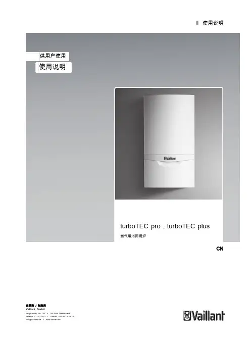
CNJNG27-VU CN 242/3-5-H JNG31-VU CN 282/3-5-H JNG41-VU CN 362/3-5-HJLG27-VUW CN 242/3-3-H JLG27-VUW CN 242/3-5-H JLG31-VUW CN 282/3-5-HJLG41-VUW CN 362/3-5-H供用户使用操作手册turboTEC pro / turboTEC plus壁挂式燃气采暖锅炉壁挂式燃气采暖/热水锅炉目录turboTEC pro / turboTEC plus系列壁挂炉特点 (2)推荐配件 (2)1 阅读提示 (3)1.1 文件保管 (3)1.2 符号说明 (3)1.3 产品名称和产品标识 (3)1.4 手册的适用性 (3)2 安全性 (4)3 操作说明 (6)3.1 关于保修期的说明 (6)3.2 特定用途 (6)3.3 安装地点要求 (7)3.4 保养 (7)3.5 循环利用和废弃处理 (7)3.6 节能提示 (7)4 壁挂炉的运行 (9)4.1 壁挂炉控制部件 (9)4.1.1 turboTECplus系列控制面板 (9)4.1.2 turboTECpro系列控制面板 (10)4.2 调试前准备 (11)4.2.1 打开管路阀门 (11)4.2.2 检查系统压力 (11)4.3 启动 (12)4.4 生活热水模式运行 (12)4.4.1 设置生活热水温度 (12)4.4.2 速热启动运行(只适用于具有热水速热功能的turboTEC plus系列壁挂炉) (13)4.4.3 取用生活热水 (13)4.5 供暖模式运行 (14)4.5.1 设置供暖供水温度(未连接外部控制器) (14)4.5.2 设置供暖供水温度 (连接有外部控制器) (14)4.5.3 关闭供暖 (夏季模式) (14)4.5.4 设置室内温控器或气候补偿器 (15)4.6 状态显示(供工程师在维护和维修时参考) (15)4.7 故障检修 (16)4.7.1 缺水引起的故障 (16)4.7.2 点火故障 (17)4.7.3 排烟系统故障 (17)4.7.4 给壁挂炉/供暖系统注水 (17)4.8 暂时关闭采暖及生活热水供应 (18)4.9 防冻保护 (18)4.9.1 防冻保护功能 (18)4.9.2 通过排水防冻 (19)4.10 维护与客户服务..............................................................19turboTEC pro / turboTEC plus系列壁挂炉特点turboTEC pro / turboTEC plus为威能新一代壁挂式燃气锅炉(以下简称壁挂炉),结构紧凑,外观庄重、大方。
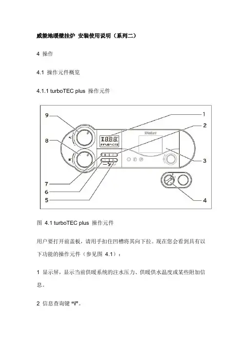
威能地暖壁挂炉安装使用说明(系列二)4 操作4.1 操作元件概览4.1.1 turboTEC plus 操作元件图4.1 turboTEC plus 操作元件用户要打开前盖板,请用手扣住凹槽将其向下拉。
现在您会看到具有以下功能的操作元件(参见图4.1):1 显示屏,显示当前供暖系统的注水压力、供暖供水温度或某些附加信息。
2 信息查询键“i”。
3 装控制器(配件)。
4 主开关,用于启动或关停燃气采暖热水炉。
5 “+” 按钮,用于向前滚动显示屏上的信息(威能技术服务人员在设置参数和排除故障时使用)和切换到显示当前供暖供水温度。
6 “-”按钮,用于显示屏的显示信息向回翻页(威能技术服务人员在设置参数和排除故障时使用)。
7 “复位”按钮,用于复位某些故障。
8 用于设置供暖供水温度的旋钮。
9 仅针对集成有生活热水供应的turboTEC:用于设置热水出水温度的旋钮。
仅针对连接有热水储水罐的turboTEC:用于设置储水罐水温的旋钮。
数字化信息和分析系统(DIA)图4.2 显示屏(turboTEC plus 取用生活用水时)turboTEC pro / turboTEC plus 系列燃气采暖热水炉配备有一个数字化信息与分析系统。
该系统可以提供燃气采暖热水炉运行状态的信息并帮助您排除故障。
在燃气采暖热水炉正常运行期间,显示屏(3) 显示供暖系统的当前注水压力(在示例中为1.2 bar = 0.12 MPa)。
如果出现故障,一个错误代码将取代注水压力的显示。
此外,还可以从所显示的符号获得以下信息:* 只适用于集成有生活热水供应(VUW) 的turboTEC plus 系列燃气采暖热水炉。
** 只适用于连接有热水储水罐(VU) 的turboTEC plus 系列燃气采暖热水炉。
表4.1 显示屏上符号的含义按住“-” 按钮约5 秒钟将显示从供暖供水温度切换为系统注水压力,反之亦然。
4.1.2 turboTEC pro 操作元件图4.3 turboTEC pro 操作元件操作元件具有下列功能(参见图4.3):1 显示屏,显示当前供暖系统的注水压力、供暖供水温度或某些附加信息。
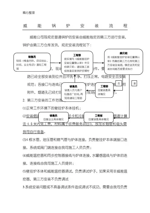
威能锅炉安装流程威能公司现规定普通锅炉的安装由威能指定的第三方进行安装,锅炉由第三方仓库发货,规定安装流程如下:⑷威能温控器和同步控制器接线与炉体连接,水罐感温线与炉体的连接,连接线由我司施工人员提供;⑸壁挂炉本体和威能温控器调试,负责调试炉子,如果采用非威能温控器,第三方安装不负责调试3.系统安装问题或不具备调试条件造成调试不成功,需要由我司负责本次200元/次上门费。
4.施工班组要准备的相关辅材,包括电线、波纹管、PPR管和管件、加长烟道、吊卡等,如需要带货安装方携带需要提前告知,付费使用,因第三方安装携带辅材价格较贵,不建议让其携带辅材安装。
5.因个人或部门原因,第三方安装出现费用问题,由责任人承担。
5、壁挂炉禁止安装在燃气灶台、水池上方;应保证壁挂炉安装位置与燃气管路及燃气表之间的距离符合国家的现行规定标准。
6、壁挂炉尽量安装在承重墙上,若无法安装在承重墙上,必须保证壁挂炉可以牢固安装。
7、壁挂炉尽量安装在厨房,设备间或封闭的阳台。
如果安装在未封闭的阳台,必须保证设备有安全的半封闭背阴环境,不能受到日光照晒和雨淋,保证水电气充足供应,最低环境温度应保证在5℃以上;威能壁挂炉为室内安装机型,不允许安装在室外。
8、壁挂炉安装需要至少保持以下距离:壁挂炉安装后距离地面安全同燃气壁挂炉耗气量匹配;燃气管路安装必须牢固固定;燃气表的选择:18kw-36kw炉型选用4m3燃气表,≥36kw-50kw炉型选用6m3燃气表,≥50kw-80kw炉型选用10m3燃气表;更大功率根据实际耗气量进行选择。
三、水管路连接壁挂炉下方应预留排水地漏,壁挂炉安装完毕后必须连接安全阀泄压管至地漏处或泄水口;采暖系统管路应安装过滤器;有龙门系统应安装自动排气阀;采暖系统管径应按需求进行严格计算;所有水路管路必须与墙面或地面进行安装固定。
四、烟道安装注:此表为TurboTEC系列壁挂炉烟道要求;每增加一个90°弯头,烟道长度减少1m;每增加一个45°弯头,烟道长度减少0.5m;垂直烟道超过0.5m,必须加装冷凝水收集器。
德国威能壁挂炉使用说明引言:一、产品概述:德国威能壁挂炉是一种燃气供暖设备,采用了先进的燃烧技术和高效的加热系统,既能够提供温暖的空气,又能够为家庭提供热水。
其主要特点包括:简洁紧凑的设计、高效的能源利用、智能化的控制系统和全面的安全保护措施。
二、安装步骤:1.在选择安装位置时,请确保墙壁牢固且能承受足够重量,并在安装位置附近有适当的排气通风设施。
2.将威能壁挂炉安装在合适的位置,并将其稳固固定在墙壁上。
3.连接燃气管道和水管道,并确保连接处密封良好,没有泄漏。
4.通过电源插头将壁挂炉连接到电源。
三、操作指南:1.打开天然气阀门,确保天然气供应畅通,并确保壁挂炉通电。
2.将壁挂炉的温度调至所需温度。
大多数威能壁挂炉配备了温度调节器,用户可以根据需要进行调节。
3.等待一段时间,直到壁挂炉达到所设定的温度。
一般情况下,壁挂炉会自动运行和停止,以维持设定的温度。
4.如果需要热水,您可以打开对应的热水龙头。
壁挂炉会自动加热水源,当水温达到设定的温度时,会停止加热。
四、保养维护:1.定期清洗灰尘和杂物,保持壁挂炉的表面干净。
2.检查燃气和水管道的连接处是否有泄漏,并及时修复。
3.定期检查和更换壁挂炉的滤网和过滤器,确保炉内燃烧清洁。
4.定期检查壁挂炉的燃烧器和火焰是否正常,如有异常请及时维修。
5.如果长时间不使用壁挂炉,请关闭天然气阀门,切断电源。
五、安全注意事项:1.在使用壁挂炉之前,请仔细阅读产品说明书,了解使用方法和注意事项。
2.在使用壁挂炉时,请确保房间内有适当的通风和排气设施,避免一氧化碳中毒。
3.按照正常操作规程使用壁挂炉,不要擅自改动或拆卸设备,以免引发火灾或其他安全事故。
结论:。
德国威能壁挂炉使用说明
德国威能壁挂炉是一种高品质、高效率的供暖设备,为用户提供舒适的取暖体验。
为了正确、安全地使用威能壁挂炉,以下是一些使用说明和注意事项:
1. 确认安装位置:在安装威能壁挂炉之前,请确保安装位置通风良好,远离易燃材料,并且有足够的空间进行维护和维修。
2. 供暖调节:威能壁挂炉配备了智能温控系统,用户可以通过控制面板或遥控器来调节供暖温度和时间,以满足不同季节和个人需求。
3. 热水功能:除了供暖功能,威能壁挂炉还可以提供热水,用户可以根据需要选择加热水温度和水量,享受热水的便利。
4. 定期检查:为了确保威能壁挂炉的正常运行,用户需要定期检查设备的排气和进气口是否畅通,并清洁灰尘和杂物。
5. 保养维护:定期进行燃气灶具的清洁和保养,保持设备的整洁和高效,延长使用寿命。
6. 安全使用:在使用威能壁挂炉时,请注意防火和防爆安全,避免在设备周围堆放易燃物品,定期检查燃气管道是否安全可靠。
7. 故障排除:如果威能壁挂炉出现故障或异常情况,用户应立即停止使用,并联系专业技术人员进行检修,切勿私自处理,以免造成安全事故。
通过以上的使用说明和注意事项,相信用户可以更好地了解和正确使用德国威能壁挂炉,享受舒适、安全的取暖体验。
祝愿您在冬季温暖舒适,生活愉快!。

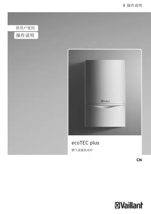
操作手册供用户使用CN操作手册turboTEC pro , turboTEC plus燃气采暖热水炉 VUW 燃气采暖热水炉(单采暖)VU目录燃气采暖热水炉特点 (3)1阅读提示 (3)1.1文件保管 (3)1.2符号说明 (4)1.3手册的适用性 (4)1.4CE 标志 (4)1.5铭牌 (4)2安全须知 (5)2.1警告提示 (5)2.1.1警告提示的分类 (5)2.1.2警告提示的结构 (5)2.2规定用途 (5)2.3对错误操作危险的警告提示 (6)3运行说明 (8)3.1保修 (8)3.2安装地点要求 (8)3.3维护 (9)3.4循环利用与废弃处理 (8)3.4.1燃气采暖热水炉废弃处理 (8)3.4.2包装废弃处理 (9)3.5节能提示 (9)4操作 (11)4.1操作元件概览 (11)4.1.1turboTEC plus 系列操作元件 (11)4.1.2turboTEC pro 系列操作元件 (12)4.2燃气采暖热水炉投入运行前准备 (13)4.2.1打开截止阀 (13)4.2.2检查系统压力 (13)4.3启动燃气采暖热水炉 (14)4.4生活热水供应 (14)4.4.1设置生活热水温度 (14)4.4.2启动和关闭速热启动功能(只适用于集成有生活热水供应的turboTEC plus 系列燃气采暖热水炉) (15)4.4.3取用生活热水 (15)4.5供暖模式运行的设置 (15)4.5.1设置供暖供水温度(未连接外部控制器) (16)4.5.2设置供暖供水温度(连接有外部控制器) (16)4.5.3设置室内温控器或气候补偿器 (16)4.5.4关闭供暖(夏季模式) (17)4.6给燃气采暖热水炉/供暖系统注水 (17)4.7防冻保护 (18)4.7.1防冻保护功能 (18)4.7.2通过排水防冻 (18)4.8将燃气采暖热水炉停止运行 (19)4.9状态显示(供威能专业技术人员在保养和维修时参考) ..........................195排除故障 .. (20)5.1缺水引起的故障 (20)5.2点火故障 (21)5.3进气或排烟通道故障 (21)6保养和售后服务 (22)6.1有关规定用途、清洁和每日维护的注意事项 (22)6.2客户服务 (22)关键词索引 (23)目录燃气壁挂式采暖热水炉特点威能 turboTEC pro/turboTEC plus 系列为结构紧凑的燃气壁挂式采暖热水炉(以下简称燃气采暖热水炉)。
威能锅炉主机设计、安装、调试注意事项
需注意以下事项:
一,设计与安装的注意事项
1,禁止室外安装,不对防冻、防雨承担责任;
2,不允许威能主机配其他品牌水箱供应生活热水;
3,禁止使用双用锅炉利用热水管网设计循环热水;
4,安装串联外置循环水泵必须与主机循环水泵型号一致,必须安装威能水泵同步控制器;
5,锅炉安装必须在采暖供回水管上安装水箱保养阀(2只)、冷水进水阀上安装Z型阀;
6,锅炉烟道必须符合烟道安装规范;
7,威能水箱安装必须根据水箱大小安装对应威能水箱安全组件;
以上是几项基本注意事项,安装须仔细查看安装手册,符合规范要求。
二,程序注意事项:
1,提取主机时需留下设备安装的详细客户信息。
包括:客户全名、电话、详细安装地址;
2,威能设备仅能安装在南京地区,特殊情况必须提前向我司即时报备;
3,我司将提供一次免费上门设备调试(限市区、限一次),浦口江北等地区我司调试收取交通费;
4,对于非设备质量原因造成的二次上门及多次上门调试,我司将收取200元/次的费用;
5,我司完成调试后,将尽快将客户信息数据报备至威能数据库,为杜绝安装后久不调试,我司将在主机提走后一个半月内将数据报备至威能数据库,二者先到者为准。
从报备之
日起将进入售后服务质保阶段;。
IST 03 C 476 - 12安装、使用以及维护亲爱的顾客:感谢您选购本公司锅炉。
请认真阅读本说明书,以便正确安装、使用及维护本设备。
禁止乱动器具密封。
所有器具密封如有破裂应要修复和重密封,所有的调整装置应密封。
安装人员、维修技术人员以及用户基本常识本说明书是本产品不可或缺的重要组成部分。
安装人员必须将本说明书交付给用户。
用户应妥善保管本说明书,以便日后参考使用。
出售锅炉或以及转让其所有权时必须附带本说明书。
本锅炉必须由合格专业人员,根据适用的法律、标准以及厂家在本说明中规定的要求安装。
安装不当可能会导致人员及/或动物伤害或财产损失。
对于此类伤害和损失,厂家概不负责。
厂家不承担任何合同内及合同外,因安装不当或使用不当或未遵守厂家要求而引起的伤害或损失。
安装之前,检查锅炉技术参数是否符合在系统中正确使用的要求。
检查锅炉是否完好无损,运输以及搬运过程中是否有损坏。
请勿安装受损及/或存在缺陷的设备。
请勿堵塞进气口。
只能安装厂家批准和提供的配件或选件(包括电气配件)以免降低产品的安全性 。
请妥善处理产品包装,鉴于本产品所有包装材料均可回收利用,应将包装材料送至专门的垃圾管理场所。
儿童和不会使用的人不应该操作器具 儿童严禁玩弄器具,请将包装材料放在远离儿童的地方,否则可能成为危险源。
请将包装材料放在儿童接触不到地方,否则可能成为危险源。
设备故障及/或运转异常时,请关闭锅炉。
联系专业维修技师,切勿尝试自行维修。
锅炉维修时只能使用厂家批准和提供的部件。
违反上述要求可能影响锅炉的安全性并危及人员、动物和财产。
厂家强烈建议顾客联系专业服务中心寻求维护维修帮助,他们均受过良好的相关培训。
如果锅炉长时间不使用,应切断它与市电的连接,关闭煤气旋塞。
注意:锅炉的电子防冻功能将无法运行。
锅炉面临冰冻风险时,加入防冻剂:请勿排空系统,否则会导致危险;请使用适合多金属加热系统的专用防冻剂产品。
3厂家不承担任何合同内及合同外,因安装不当或使用不当或未遵守厂家要求而引起的伤害及/或损失。
威能地暖壁挂炉安装使用说明〔系列二〕4 操作4.1 操作元件概览4.1.1 turboTEC plus 操作元件图4.1 turboTEC plus 操作元件用户要打开前盖板,请用手扣住凹槽将其向下拉。
现在您会看到具有以下功能的操作元件〔参见图4.1〕:1 显示屏,显示当前供暖系统的注水压力、供暖供水温度或某些附加信息。
2 信息查询键“i〞。
3 装控制器〔配件〕。
4 主开关,用于启动或关停燃气采暖热水炉。
5 “+〞按钮,用于向前滚动显示屏上的信息〔威能技术服务人员在设置参数和排除故障时使用〕和切换到显示当前供暖供水温度。
6 “-〞按钮,用于显示屏的显示信息向回翻页〔威能技术服务人员在设置参数和排除故障时使用〕。
7 “复位〞按钮,用于复位某些故障。
8 用于设置供暖供水温度的旋钮。
9 仅针对集成有生活热水供给的turboTEC:用于设置热水出水温度的旋钮。
仅针对连接有热水储水罐的turboTEC:用于设置储水罐水温的旋钮。
数字化信息和分析系统(DIA)图4.2 显示屏〔turboTEC plus 取用生活用水时〕turboTEC pro / turboTEC plus 系列燃气采暖热水炉配备有一个数字化信息与分析系统。
该系统可以提供燃气采暖热水炉运行状态的信息并帮助您排除故障。
在燃气采暖热水炉正常运行期间,显示屏(3) 显示供暖系统的当前注水压力〔在示例中为1.2 bar = 0.12 MPa〕。
如果出现故障,一个错误代码将取代注水压力的显示。
此外,还可以从所显示的符号获得以下信息:* 只适用于集成有生活热水供给(VUW) 的turboTEC plus 系列燃气采暖热水炉。
** 只适用于连接有热水储水罐(VU) 的turboTEC plus 系列燃气采暖热水炉。
表4.1 显示屏上符号的含义按住“-〞按钮约5 秒钟将显示从供暖供水温度切换为系统注水压力,反之亦然。
4.1.2 turboTEC pro 操作元件图4.3 turboTEC pro 操作元件操作元件具有如下功能〔参见图4.3〕:1 显示屏,显示当前供暖系统的注水压力、供暖供水温度或某些附加信息。
威能锅炉使用说明
威能锅炉是一款高效、可靠的热水供暖设备,本文将为您提供详细的使用说明,以确保您正确、安全地操作威能锅炉。
1. 开启锅炉:在使用威能锅炉前,请确保供电正常并确认水压在安全范围内。
打开供水阀门,并将控制器设置为合适的温度和时间。
2. 温度控制:通过控制器上的温度设定按钮,您可以调整锅炉的加热温度。
根
据您的需要,可以将温度设定为适宜的供暖温度。
请注意,过高的温度设定可能造成危险,所以请务必谨慎使用。
3. 时间设定:通过控制器上的时间设定按钮,您可以设置锅炉的运行时间。
根
据您的供暖需求,可以将锅炉设定为适当的运行周期。
威能锅炉配备了智能节能功能,可以根据实际需求自动调节时间,以确保供暖效果和能源利用效率的最佳平衡。
4. 安全操作:在使用威能锅炉时,请务必注意以下安全事项:
a. 确保供水管道畅通,检查水压是否在正常范围之内;
b. 定期清洁锅炉内部,以防止积灰和水垢对热交换器的影响;
c. 确保锅炉周围的通风良好,避免堵塞;
d. 如果发现任何异常现象或故障,请立即断电并咨询专业人士进行维修。
5. 维护保养:为了确保威能锅炉的长期稳定运行,请定期进行维护保养。
这包
括清洁燃料喷嘴、更换滤网、检查电路连接等。
建议找专业的维修人员进行定期维护,以延长锅炉的使用寿命。
威能锅炉的使用说明如上所述,请在使用前仔细阅读并遵照本文提供的指导进
行操作。
如有任何疑问或需要进一步的帮助,请联系威能锅炉的客服部门,他们将乐意为您提供支持和解答。
祝您使用愉快,享受温暖的供暖体验!。
Technical Data ManualVITOCROSSAL200Gas-fired Condensing Boiler1445 to 2245 MBH (423 to 658 kW)Model Nos. and pricing : See Price ListVitocrossal 200CM2 Series 400, 500, 620 and 620 TXHigh efficiency, gas-fired condensing boilerwith pre-mix modulating cylinder burnerfor natural gas or liquid propane gas with Inox-Crossal heatexchanger made of high-grade SA 240-316 Ti stainless steel.For operation without low limit on boiler return watertemperature.For closed loop hot water heating systems with maximumsupply water temperatures of 210° F (99° C) for amaximum operating pressure of 75 psig.Heating input: 1445 to 2245 MBH(423 to 658 kW)Product may not be exactly as illustrated.H73 596 - 03Benefits at a glance:Inox-Crossal heat exchanger surface made of high- grade SA 240-316 Ti stainless steel for high operational reliability and long service life. - Easy dispersal of condensate through vertical gas flues; therefore no concentration of condensate. - Increased self-cleaning effect through smoothstainless steel surfaces.Highly efficient heat transfer and high condensation rate through - highly turbulent flow of flue gas through the heat exchanger.- boiler water and hot gases flowing in counter flow.Efficiency up to 98% through intensive condensation. The flue gas temperature is only approximately 9-27° F (5 - 15° C) above boiler return temperature (see chart below).Clean combustion - through perfect match of burner and boiler, low combustion chamber loading andstraight-through combustion chamber.Easy handling in boiler rooms through particularly lowbuild height and weight.Easy installation and elimination of wiring mistakeswith Viessmann pre-wired plug-in system.Heating boiler, heating system control, domestic hot water storage tank and all other Viessmann system technology components are coordinated to one another. All components are design-matched for quick installation.Pre-mix cylinder burner for environmentally-friendly operation with a modulation range from 20 to 100%.All hydronic connections can be fitted from above.Economical and safe heating system operation through Vitotronic digital control system with communication capability. Tailored to every need, covering all known control strategies and applications. Standard LON BUS for complete integration intobuilding management systems.Particularly quiet operation.High altitude operation up to 10,000 ft. (3000 m) with a simple electronic adjustment.Vitocrossal 200 boiler efficiency dependent on system heating water return temperatures and load conditionsB o i l e r E f f i c i e n c y i n %System Partial Load in %DesignSupply / Return104° F - 88° F (40° C - 30° C)Curve 0.5DesignSupply / Return 167° F - 140° F (75° C - 60° C)Curve 1.4DesignSupply / Return 194° F / 158° F (90° C - 70° C)Curve 1.8Outdoor TemperatureB o i l e r W a t e r / S u p p l y T e m p e r a t u r eRoom Set-Point Temperature73 596 - 03LegendA Supply/return temperature of 176/140° F (80/60° C)B Supply/return temperature of 158/122° F (70/50° C)C Supply/return temperature of 140/104° F (60/40° C)D Supply/return temperature of 122/86° F (50/30° C)E Supply/return temperature of 104/68°F (40/20° C)Flue gas temperature as a function of average partial load firings.73 596 - 03LegendA Stainless steel Inox-Crossal heat exchangerB Highly effective thermal insulationC Water-cooled stainless steel combustion chamberD Wide water passageways - good natural circulationE Modulating MatriX cylinder burner73 596 - 03Boiler Model CM2400500620620 TX InputMBH 1445180022451999*3(kW)(423)(527)(658)(585)Minimum Input NG MBH 287358450450(kW)(84)(105)(132)(132)Minimum Input LPG MBH 351440545545(kW)(103)(129)(160)(160)Output *1MBH (kW)1372(402)1710(501)2132(625)1899*2(556)Net AHRI ratingMBH (kW)1193(350)1487(436)1854(543)1651(484)Combustion efficiency *1%95.195.195.195.1*2Thermal efficiency *1%95.095.095.095.0*2Overall length(e)in.89b 955/81007/81007/8(mm)(2273)(2429)(2562)(2562)Overall width (c)in.423/8423/8443/8443/8(including insulation)(mm)(1078)(1078)(1128)(1128)Overall height (a)in.655/8655/868c 68c (including control unit)*4(mm)(1666)(1666)(1748)(1748)Concrete boiler base Lengthin.465/8535858(mm)(1185)(1345)(1475)(1475)Widthin.42.542.544.544.5(mm)(1245)(1245)(1295)(1295)Thickness in.4444(mm)(100)(100)(100)(100)Weight Boiler bodylb 1136125714881488(Kg)(515)(570)(675)(675)Complete with the burner, control lb 1495166219291929and thermal insulation(Kg)(678)(754)(875)(875)*1 Tested to U.S. Standards ANSI Z21.13/CSA 4.9 and AHRI, BTS-2000 Testing Standard Method to determine the efficiency of Commercial Heating Boilers.*2 T ested to U.S. Standards ANSI Z21.13/CSA 4.9.*3 Boilers with this maximum input rating is only offered in the USA.*4 A dd 1f in. (40 mm) when using seismic mounts (optional accessory).Note: For altitude operation up to 4,999 feet, derate the input capacity by 3%/1000 ft. For operation from 5,000 to 10,000 feet, with the electronic altitude adjustment made, derate the input capacity by an additional 0.6%/1000 ft. for a total derate of 18%.AA Input capacity after electronic altitude adjustment is made.73 596 - 03Boiler ModelCM2400500620620 TX Boiler Water ContentUSG 104112131131(L)(395)(425)(495)(495)Heat exchanger surface ft.2166.6208.6234234water cooled(m 2)(15.5)(19.4)(21.7)(21.7)Maximum Operating Temperature °F (°C)210 (99)210 (99)210 (99)210 (99)Maximum Adjustable High Limit °F (°C)203 (95)203 (95)203 (95)203 (95)Maximum Operating Pressure psig 75757575(bar)(5)(5)(5)(5)Boiler ConnectionsBoiler supply and return (BS), (BR)in.4444(ANSI flanges)(mm)(100)(100)(100)(100)Safety Supply in.1a 1a 1a 1a Boiler Drainin.1b1b1b1bCondensate Drain in.¾¾¾¾Vent pipeInternal Diameterin.10101010(mm)(252)(252)(252)(252)Flue Gas Valuestemperature (at a returntemperature of 86° F (30° C)at rated input °F 113113113113(°C)(45)(45)(45)(45)at partial load°F 86868686(°C)(30)(30)(30)(30)Temperature (at a returntemperature of 140° F (60° C)at rated input°F 167167167167(°C)(75)(75)(75)(75)Mass flow rate (of flue gas)at rated inputlbs/h 1276158719861767(kg/h)(579)(720)(901)(802)at partial loadlbs/h 255317399399(kg/h)(116)(144)(181)(181)Pressureat boiler flue outlet pa 70707070at rated input “w.c.0.280.280.280.28Standby lossat maximun input and steady state condition 180° F/80° F (82° C/27° C) supply and return water temperatureBTU/h (W)%1878 (550)0.132520 (738)0.143367 (986)0.153367 (986)0.15At boiler water temperature 158° F (70° C) [roomtemperature 68° F (20° C)]BTU/h (W)%4335 (1270)0.35400 (1580)0.36735 (1973)0.36735 (1973)0.373 596 - 03LegendA Boiler LengthB Boiler WidthC Boiler Height AGA Flue outletBO Inspection Opening (Canada only)E DrainKOA Condensate drainKTS Boiler water temperature sensor KR Boiler return KV Boiler flowRG Female connection R b for additional control equipment (e.g. fitting assembly with minimum and maximum pressure switch)SA safety connection (safety valve)STB Flue outletDimensions Model CM2400500620620 TX a*in. (mm)655/8 (1666)655/8 (1666)68c (1748)68c (1748)b*in. (mm)56a (1428)56a (1428)59b (1511)59b (1511)c in. (mm)423/8 (1078)423/8 (1078)443/8 (1128)443/8 (1128)d=B in. (mm)35c (910)35c (910)37c (960)37c (960)e in. (mm) 89b (2273)955/8 (2429)1007/8 (2562)1007/8 (2562)f in. (mm)85a (2163)85a (2319)96c (2455)96c (2455)g in. (mm)46c (1187)527/8 (1343)58a(1477)58a (1477)h=A in. (mm) 59 (1497)65 (1650)703/8 (1787)703/8 (1787)i in. (mm)217/8 (555)28c (713)33b (851)33b (851)j=BO in. (mm) 4 (101) 4 (101) 4 (101) 4 (101)k in. (mm) 34a (870)34a (870)345/8 (879)345/8 (879)l in. (mm)15d (383)12c (435)187/8 (480)187/8 (480)m in. (mm) 10 (254)12d (308)13c (351)13c (351)n in. (mm)12b (318)145/8 (370)163/8(415)163/8(415)o in. (mm) 2c (70)2c (70)25/8 (67)25/8 (67)p*in. (mm)277/8 (708)277/8 (708)29 (736)29 (736)q*in. (mm)53b (1360)545/8 (1387)57b (1460)57b (1460)r=C*in. (mm)583/8 (1482)593/8 (1509)62a (1582)62a (1582)s in. (mm)23c (601)23c (601)23c (601)23c (601)t*in. (mm)9 (229)9 (229)9 (229)9 (229)u*in. (mm) 57/8 (149) 57/8 (149)57/8 (149)57/8 (149)vin. (mm)5a (133)5a (133)5a (133)5a (133)* Add 1f in. (40 mm) when using seismic mounts (optional accessory).73 596 - 03Mechanical roomotherwise the system may suffer faults and damage. In rooms where air contamination from halogenated hydrocarbons is to be expected, operate the boiler only in balanced flue mode.Minimum clearances to combustibles Boiler model CM2400500620620 TXTop 0Sides 0Flue As per vent manufacturer’s specificationsFront 0FloorcombustibleLegend A Boiler B Burner*1 Clearance may be reduced to zero in multi-boiler installations, provided the side panel removal is not required.Note: The burner, boiler control, condensate trap, venting and heat exchanger are still fully accessible from the front and rear of the boiler.*2 Clearance for vent pipe installation.To enable convenient installation and maintenance, observe the stated clearance dimensions. Maintain the minimum clearances where space is tight.In the delivered condition, the boiler door hinge bracket is factory installed on the left side of the door. If required, the boiler door hinge bracket can be reinstalled on the right side of the door. CM2400500620/620 TX a *1 in. (mm)20 (500)20 (500)20 (500)b *2 in. (mm)30 (760)30 (760)30 (760)c in. (mm)20 (500)20 (500)20 (500)d in. (mm)20 (500)20 (500)20 (500)e in. (mm)24 (600)24 (600)24 (600)f in. (mm)11 (280)11 (280)11 (280)g in. (mm)15b (395)15b (395)15b (395)73 596 - 03Pressure drop (primary circuit)The Vitocrossal 200 is only suitable for fully pumped hot water heating systems.Recommended Flow Rates CM2Boiler model 400500620620 TX 20° F ❒t GPM 137.2171.0213.2198.940° F ❒t GPM 68.685.5106.695.011° C ❒t m 3/h 31.138.848.443.222° C ❒tm 3/h15.519.424.221.6❒t = temperature differenceThis boiler does not require a flow switch.P r e s s u r e dr o pFlow rate73 596 - 03Specifications Boiler Model CM2400500620620 TX Voltage V 120120120120FrequencyHz60606060Power consumption NG at max. input W 540700900801at min. inputW54606060Power consumption LPG at max. input W 467590700623at min. input W59686060Version modulatingDimensionsLength in. (mm)385/8 (980)385/8 (980)41¾ (1060)41¾ (1060)Widthin. (mm)26 (661)265/8 (675)265/8 (675)265/8 (675)Height in. (mm)21a (540)205/8 (525)24b (622)24b (622)Weight Burner onlyBurner package (with kits, flanges and mounting hardware)lb. (kg)lb. (kg)75 (34)91 (41.3)90 (41)90 (41)93 (42)93 (42)93 (42)93 (42)Min. gas supply pressure Natural gas “w.c.4444Liquid propane gas “w.c.10101010Max. gas supply pressure Natural gas “w.c.14141414Liquid propane gas “w.c.14141414Gas connectionNPT1a1a1a1a115773 596 - 03CM2 pre-mix cylinder burner 400/500/620/620 TXLegendA Burner frameB Air pressure switch 1C Air pressure switch 2D Display and programming unitE Gas valveF Gas supply pipeG Gas pressure switchH Rotary damper with servomotor (400, 620 and 620 TX only)I Gas pipeJ Manual shut-off valve K Venturi mixing pipe L Gas fanM Burner gauze assembly N Ignition electrodes O Ionization electrode P Ignition unitQBurner control unitR Mains filter unit with contactorCM2 Boiler model 400500620620 TX a in. (mm)20 (506)20 (506)20 (506)20 (506)b in. (mm)385/8 (980)385/8 (980)41c (1060)41c (1060)c in. (mm)26 (661)265/8 (675)265/8 (675)265/8 (675)din. (mm)21a (540)20f (525)24b (622)24b (622)125773 596 - 03Installation fittings for standard equipment includes:- low water cut-off- safety header (c/w 75 psig pressure relief valve, air vent and pressure gage)- drain valve - product documentation - combustion air intake kit - NG to LPG conversion kitVitotronic 300 (type GW5B) and LON module for modulating boiler water temperature for eachboiler of the multi-boiler system and Vitotronic 300 (type GW5B) and LON module for modulating boiler water temperature inconjunction with an external control unit (BMS). Vitocontrol-S, CM2 control panelwith Vitotronic (300-K, type MW1B) for multi-boiler system, outdoor reset mode and mixing valve control for a m aximum of 2 heating circuits with mixing valve and additional Vitotronic 200-H, type HK1B for 1heating circuit with mixing valve.For single boiler systemsVitotronic 300 (type GW5B)Outdoor reset control for stand alone operation, for modulating water temperature with mixing valve(optional expansion board for two additional circuits).CM2 Boiler model 400500620620 TX Thermal insulation 2222Cylinder burner1111Boiler control unit (see boiler control alternatives below)1111Boiler coding card 1111Technical documentation 2222Combustion air intake kit 1111Junction box1111Boiler body with fitted mating ANSI flanges and gaskets to all connectors and fitted protective crate, plus flue gas collector collar.For single-boiler or multiple-boiler installationsCustom control panels for residential or commercialapplications are designed and manufactured by Viessmann to suit any customer’s specific requirements. Customcontrol panels can integrate features such as pool heating, hot tub heating, snow melting, telephone tie-in, integration with Building Management Systems, as wellas several other functions. Please inquire.Refer to the common venting flue vent damper Installation Instructions.- Motorized flue gas damper (for cascade venting system)135773 596 - 03Note: The ‘amount of condensate” and the “flue gas temperature gross” graphs are independent of each other.Condensate and its disposalDuring the operation of the boiler, the amount ofcondensate to be expected can be read from the above diagram.The values given are approximate amounts occurring under practical conditions. Not included in the diagram is the amount of condensate occurring in the vent pipe and chimney system. The condensate from the chimney system can be collected together with the condensate from the heating boiler and be disposed of into a floor drain. The condensate will be between 3 and 4 on the pH scale. If local building requirements demand neutralizing the condensate before disposal, contact Viessmann Manufacturing Company Inc. for a correctly sized neutralization tank. The treated condensate will show pH values of between 6.5 and 9 and can then be disposed of into the waste water system.Design notes regarding draining condensateThe condensate drain to the sewer connection must be able to be inspected.Route it with a gradient and equip the pipe with a P-trap; also provide suitable facilities for taking samples.The bottom drain should be located below the anti-flooding level of the flue gas collector box.Condensate drains must only be made from corrosion resistant materials (e.g. fibre reinforced hoses). Never use any galvanized materials or those containing copper or black iron for pipes, connectors, etc.Install a P-trap in the condensate drain to prevent flue gases from escaping.Venting optionsPP(s) (Polypropylene) flue gas/fresh air system for room air independent operation (sealed combustion), and PP(s) flue gas for room air dependent operation are tested to ANSI Z21.13 - CSA 4.9 - 2000 standards and are certified together with the Vitocrossal 200 boiler as a constructional unit.The Vitocrossal 200 boiler may also be vented using an special stainless steel, single-wall, (UL listed for category IV).The boiler may be vented horizontally through the side wall or vertically through the roof.For a more detailed description of the direct vent and single-wall vent system, please refer to the Vitocrossal 200 Installation Instructions venting section.Use ULC S-636 / UL 1738 certified for category IV boilers. The following vent system suppliers may be contacted for assistance in designing the appropriate PP(s) venting system for Vitocrossal 200 CM2 boilers.M&G / Duravent Tel. 800-835-4429Tel. 518-649-9700Fax: 518-463-5271Email:******************Web: Centrotherm InnoFlue Eco Systems. L.L.C.Tel. (877) 434-3432Fax. (518) 618-3166Email:*******************.com Web: A m o u n t o f c o n d e n s a t eBoiler water return temperatureF l u e g a s t e m p e r a t u r e g r o s sF l u e g a s t e m p .a t f u l l i n p u ta t pa r t i a l l o ad F l ue g a s t e m p .A m o u n t o f c on d e n s a t e Ensure that the domestic drainage systems are madefrom materials which are resistant to acidic condensatesuch as:Burner adjustmentMartix cylinder burner tested at operating temperature and adjusted in the factory.145773 596 - 03System layoutThe boiler water temperature limit is factory set to 167° F (75° C).The boiler water temperature limit can be increased by altering the adjustable high limit (AHL) to increase the supply water temperature.To minimize piping losses of the system, however,Viessmann recommends that the radiation and domestic hot water production in the system be designed for a 158° F (70° C) boiler supply water temperature.WarrantyOur warranty does not cover damages resulting from the following:- Operation with contaminated fill and supplementary feed water- Operation with contaminated combustion air- Exposing the boiler to pressures and temperatures higher than its certified rating See warranty sheet for details.Use ULC S-636 / UL 1738 certified venting systems for category IV boilers. The following vent system suppliers may be contacted for assistance in designing theappropriate stainless steel venting system for Vitocrossal 200 CM2 boilers.Combustion air supplyThe boiler must not be located in areas or rooms where chemicals containing chlorine, bromine, fluorine, or other corrosive chemicals are stored. Examples include bleach, refrigerants, paint, paint thinner, hair spray, cleaning solvents, water softener salt, etc. The combustion air must not be contaminated with any amount of the above mentioned chemicals.Boiler should never be installed in areas where excessive dust, high humidity, or risk of frost exist. Ensure adequate ventilation and supply of fresh combustion air.Consult your local Viessmann sales representative with uncertainties in regard to a suitable boiler installation location.This boiler/burner unit needs clean fresh air for safe operation. Provisions for combustion and ventilation air must be made at time of installation. For gas or propane installations, use the “Natural Gas Installation Code CAN/CSA-B149.1 or B149.2” (Canada), or “National Fuel Gas Code ANSI Z223.1” (USA), and/or provisions of local codes.The sizing methods outlined in the aforementioned codes should be used when installing a round duct to supply combustion air from the outside.M&G / Duravent Tel. 800-835-4429Tel. 518-649-9700Fax: 518-463-5271Email:******************Web: ICC - Industrial Chimney Co.400 J-F Kennedy,St-Jerome, Quebec Canada, J7Y 4B7Tel. 514-565-6336Fax: 514-565-6519Email:*****************Selkirk Canada Corporation 375 Green RoadStoney Creek, ON L8E 4A5Tel.: (905) 662-6600Fax: (905) 662-5352(US) 1-800-992-8368(Canada) 1-888-735-5475Email:********************Web: Novaflex1-20 East Pearce St.,Richmond Hill, Ontario,Canada, L4B 1B7Tel. 905-731-9411Email:********************Wesmech Technical Sales 50 Ronson Drive, Suite 160Toronto, ON M9W 1B3Tel.: (416) 251-8990Fax: (416) 251-89001-800-613-3789Email:********************Web: Van-Packer Co. Inc.302 Mill Street PO Box 307Buda, IL 61314Tel.: (309) 895-2311Fax: (309) 895-38911-888-877-8225Email:*******************Web: Security Chimneys International Ltd.2125 Rue Monterey, Laval, Quebec H7L 3T6Tel. 450-973-9999(US) 1-800-361-4909(Canada) 1-800-667-3387Fax: 450-973-2222Email: infoeng@Web: Enervex Inc.(formerly Exhausto)Tel: 770-587-3238Fax: 770-587-4731(800) 225-2923Email:*****************Web:Centrotherm InnoFlue Eco Systems. L.L.C.Tel. (877) 434-3432Fax. (518) 618-3166Email:*******************.com Web: 155773 596 - 03Airborne noise attenuationFrequently, modern boilers are equipped with silencer hoods or sound insulated ventilation air inlet housings.For larger systems, it may be necessary to route theventilation air through a sound-insulated channel, in order to avoid a noise nuisance outside the building.Flue gas silencers are generally only required where higher noise protection measures are called for. Whether or not a flue gas silencer is required can be predicted only with some difficulties, because of the complexity of the creation and propagation of flame noise, the interaction between the burner, boiler and the flue gas system as well as the operating mode (flue gas system operating with positive or negative pressure).It is advisable, therefore, to assess the noise emission into the neighborhood and to consider the sound pressure level measured at the flue gas system outlet. It should beconsidered at the planning stage whether silencers might become necessary later.In planning for its possible use, it is important thatsufficient space for the flue gas silencer is available behind the boiler. Good engineering practice mandates that the exhaust pressure drop of the silencer be included in the vent size calculation.Anti-vibration measuresAnti-vibration supports can be field supplied as an economical and effective solution to combat noise generated.When sizing such supports, take the entire operating weight of the boiler system and, when using longitudinal anti-vibration brackets, the condition of the supporting surface into consideration.Effective anti-vibration measures are particularly important when installing boilers into an attic. Flexible couplings may be used to physically separate the combustion equipment from the building.These should be installed into the boiler flow, return and safety pipe and as near as possible to the boiler.Also insulate any braces or hanging arrangements, if installed, against sound/vibration transmission to the building.Water qualityTreatment for boiler feed water should be considered in areas with known problems, such as where a high mineral content and hardness exist. In areas wherefreezing might occur, it recommended that an antifreeze be added to the system water for protection againstfreezing. Please adhere to the specifications given by the antifreeze manufacturer. Do not use automotive silicate-based antifreeze. Please observe that an antifreeze/water mixture may require a back flow preventer within the automatic water feed and influence components such as diaphragm expansion tanks, radiation, etc. A 40% antifreeze content will provide freeze-upprotection to -10° F (-23° C). Do not exceed 50%antifreeze mix ratio and do not use antifreeze other than specifically made for hot water heating systems. Oxygen diffusion barrier under floor tubingThe boiler warranty does not cover pressure vessel failure resulting from corrosion caused by the use of underfloor plastic tubing without an oxygen diffusion barrier. Such systems without oxygen diffusion barrier must have the tubing separated from the boiler with a heat exchanger. Viessmann always recommends the use of underfloor plastic tubing with an oxygen diffusion barrier.Boiler/burner start-upVitocrossal 200, CM2 boilers with Viessmann cylinder burners does not require start-up by Viessmann. Sound attenuationPlease consult a professional engineer who is specialized in noise attenuation for advice.The burner/boiler systems, circulation pumps and other auxiliary equipment used in heating systems generate noise.This noise is transferred from the boiler room viafloorboards, ceiling and walls to neighboring rooms and via the flue gas system as well as the ventilation air and exhaust air apertures into other rooms and into the open, where they may cause a nuisance.To avoid this from happening, additional protective measures may be required which should be considered at the design stage.Subsequent measures to reduce noise nuisance frequently require extensive effort and expenditure.Total output (MBH)Total Hardness (ppm as ca CO 3)> 1 Total 680 200> 680 to 2050150The pH value of the heating water should be between 8.2 and 9.55773 596 - 03 T e c h n i c a l i n f o r m a t i o n s u b j e c t t o c h a n g e w i t h o u t n o t i c e.P r i n t e d o n e n v i r o n m e n t a l l y f r i e n d l y (r e c y c l e d a n d r e c y c l a b l e ) p a p e r.。
威能壁挂炉如何安装(四)烟道的安装(2011-08-06 22:06:56)▼威能进口燃气壁挂炉 turboTEC plus 和 turboTEC pro 使用的同轴烟道尺寸均为60/100,用水钻在墙上开孔的孔径建议为110mm 。
从墙上烟道中心到壁挂炉顶部的距离为125mm烟道中心到壁挂炉底部的距离为925mm建议:烟道中心到水暖接口的距离为1125mm(壁挂炉底部到水暖接口安装距离预留200mm)下图烟道中心到背面的距离对于烟道背出安装的没有多大意义,但对于烟道侧出安装比较重要,因为此尺寸可以确定烟道中心的位置,147mm。
威能国产燃气壁挂炉 turbo 18kw 24kw 使用的同轴烟道尺寸为60/100,用水钻在墙上开孔的孔径建议为110mm。
从墙上烟道中心到壁挂炉顶部的距离为110mm烟道中心到壁挂炉底部的距离为850mm建议:烟道中心到水暖接口的距离为1050mm(壁挂炉底部到水暖接口安装距离预留200mm)威能国产燃气壁挂炉 turbo 28kw 35kw 使用的同轴烟道尺寸为80/125,用水钻在墙上开孔的孔径建议为140mm。
从墙上烟道中心到壁挂炉顶部的距离为160mm烟道中心到壁挂炉底部的距离为960mm建议:烟道中心到水暖接口的距离为1160mm(壁挂炉底部到水暖接口安装距离预留200mm)下图烟道中心到背面的距离对于烟道背出安装的没有多大意义,但对于烟道侧出安装比较重要,因为此尺寸可以确定烟道中心的位置。
威能燃气壁挂炉烟道安装1. 根据上面给出的烟道中心到挂板的尺寸,把威能燃气壁挂炉拷到墙上。
2. 将烟道连同密封墙垫一起通过墙孔伸出墙外,然后向内拉,直到密封墙垫紧贴在外墙上。
3. 将90°弯头插入水平烟道的排烟管中4. 将90°弯头另一端压入壁挂炉的排烟/进气口内。
5. 保证出墙烟道端口距墙110mm。
6. 烟道出墙处应向下倾斜2-3°,以使冷凝水不会倒流入燃气采暖热水炉。