TP83
- 格式:pdf
- 大小:171.81 KB
- 文档页数:10
User Guide©2023 TP-Link 1910013431 REV2.0.0ContentsAbout This Guide (1)Introduction (2)Appearance (3)Set Up Y our Camera (5)Set Up Using Amazon Frustration-Free Setup (6)Install a microSD Card (10)Mount Y our Camera (11)How to Reset Your Camera (12)Authentication (13)About This GuideThis guide provides a brief introduction to the Pan/Tilt Home Security Wi-Fi Camera and the T apo app, as well as regulatory information.Please note that features available in Tapo may vary by model and software version. T apo availability may also vary by region. All images, steps, and descriptions in this guide are only examples and may not reflect your actual Tapo Camera experience.ConventionsMore Info• Specifications can be found on the product page at https://.• Our T echnical Support and troubleshooting information can be found at https:///support/.• The setup video can be found at https:///support/setup-video/#cloud-cameras.1IntroductionWhen you are away home, there are always something you care about. This is where the smart camera functions. No matter your child is climbing the kitchen cabinet, or the pet is stealing snacks, the Pan/Tilt Home Security Wi-Fi Camera helps you stay with them anytime, anywhere. Receive a notification whenever your camera detects motion and see a video clip of this motion to check everything.• Motion Detection and Tracking – Whenever a camera detects motion, it will automatically follow the subject, keeping it within the camera’s field of view.• Person Detection – Notifies you when a person is detected.• Night Vision up to 30 ft – Provides a visual distance of up to 30 ft in total darkness.• Two-Way Audio – Communicate in real time through a built-in microphone and speaker.• Baby Crying Detection – Notifies you when your baby cries.• Field of View – 360º horizontal range.• Customizable Block Zones – Set customizable block zones to keep private areas from being monitored.• 2K Definition – Provides more crisp details.• Cloud Storage Supported – Store videos by using cloud storage services.*Subscribe for cloud storage at https:///tapocare/• Local microSD Storage – Store up to 512 GB of video on a microSD card.**microSD card purchased separately.2System LED Indication4Set Up Y our Camera Follow the steps below to get started with your new camera.Step 1. Download Tapo App Get the Tapo app from the App Store or Google Play, or by scanning the QR code below.Step 2. Log InOpen the app, and log in with your TP-Link ID.If you don't have an account, create one first.Step 3. Add Y our CameraT ap the button in the app and selectyour model. Follow the app instructions tocomplete setup.OR5Set Up Using Amazon Frustration-Free SetupWhat is Amazon Frustration-Free Setup?Amazon Frustration-Free Setup can help connect and set up T apo smart devices in fewer steps, without having to remember and re-enter your Wi-Fi password on each device.T o use this feature, confirm the following:● The new T apo device supports Amazon FFS.● The new T apo device is purchased from Amazon.● You have an Amazon FFS enabled Alexa device or router.● You have saved your Wi-Fi information to Amazon by using Alexa echo.● Your Tapo device and router are on the same network as your Alexa echo.If the LED does not turn solid green after a long time, you can try to add the T apo device manually. (Press the Reset button on your Tapo device once. Then open the T apo app, tap the + button on the page, select your device model, and follow the app instructions. )671. Open the Amazon Alexa app. Then tap More and select Skills & Games .How to use Amazon Frustration-Free Setup with Tapo devices2. Enter T apo in the search bar and choose T apo.83. T ap the ENABLE TO USEbutton.4. Log in with your TP-Link ID that has bound to your T apo device, and tap Authorize . After authorized successfully, the message T apo has been successfully linkedwill come up.5. Plug in your Tapo device and the setup will complete automatically in two minutes.For setting up more T apo devices, just plug in and enjoy!Done!If this device displays on the Home page in the T apo app, it indicates this device has been successfully associated with your Amazon account and joined your Wi-Fi network automatically.If this device does not display on the Home page in the T apo app, try setting it up manually. (T ap the + button on the page, select your device model, and then follow the app instructions.)9Install a microSD CardFollow the steps below to install the microSD card for local recording.You can go to Camera Settings > microSD Card in the Tapo app to check the card status or format your card.1. Manually rotate the camera downwards and find the microSD card slot.2. Identify the direction of the microSD card and carefully insert the card into the slot. Push in the card until you hear a clicking sound.10Mount Y our CameraWhen you finish adding your camera in the T apo app, you can set it on a table or shelf. You can also mount it on a wall or ceilingwith the provided mounting template and screws. Follow the steps below to mount your new camera or follow the setup video at https:///support/setup-video/#cloud-cameras.Place the mounting template where youwant the camera. For wall mounting, drilltwo holes through two circles.1. Mark PositionAttach the camera on the baseand rotate to secure the camera.3. Secure Camera2. Mount BaseAffix the camera base using the screws.For wall mounting, insert two anchorsinto the holes and use the screws toaffix the camera base over the anchors.11How to Reset Y our CameraFollow the steps below to reset your camera via the Reset button.You can also go to Camera Settings in the T apo app and tap Remove Device at the bottom to factory reset your camera.1. Manually rotate the camera downwards to find the Reset button.2. Press and hold the RESET button to reset the camera.• Press and hold for 5s until the LED blinks red slowly: Reset Wi-Fi settings only• Press and hold for 10s until the LED blinks red quickly: Reset to factorysettingsReset Button12AuthenticationFCC compliance information statementProduct Name: Pan/Tilt Home Security Wi-Fi CameraModel Number: Tapo C211Component Name ModelI.T.E. Power Supply T090060-2B1Responsible Party:TP-Link USA CorporationAddress: 10 Mauchly, Irvine, CA 92618Website: /us/T el: +1 626 333 0234Fax: +1 909 527 6804E-mail:*********************This equipment has been tested and found to comply with the limits for a Class B digital device, pursuant to part 15 of the FCC Rules. These limits are designed to provide reasonable protection against harmful interference in a residential installation. This equipment generates, uses and can radiate radio frequency energy and, if not installed and used in accordance with the instructions, may cause harmful interference to radio communications. However, there is no guarantee that interference will not occur in a particular installation. If this equipment does cause harmful interference to radio or television reception, which can be determined by turning the equipment off and on, the user is encouraged to try to correct the interference by one or more of the following measures:• Reorient or relocate the receiving antenna.• Increase the separation between the equipment and receiver.• Connect the equipment into an outlet on a circuit different from that to which the receiver is connected.• Consult the dealer or an experienced radio/ TV technician for help.This device complies with part 15 of the FCC Rules. Operation is subject to the following two conditions:1. This device may not cause harmful interference.2. This device must accept any interference received, including interference that may cause undesired operation.Any changes or modifications not expressly approved by the party responsible for compliance could void the user’s authority to operate the equipment.Note: The manufacturer is not responsible for any radio or TV interference caused by unauthorized modifications to this equipment. Such modifications could void the user’s authority to operate the equipment.FCC RF Radiation Exposure StatementThis equipment complies with FCC RF radiation exposure limits set forth for an uncontrolled environment. This device and its antenna must not be co-located or operating in conjunction with any other antenna or transmitter.“T o comply with FCC RF exposure compliance requirements, this grant is applicable to only Mobile Configurations. The antennas used for this transmitter must be installed to provide a separation distance of at least 20 cm from all persons and must not be co-located or operating in conjunction with any other antenna or transmitter.”We, TP-Link USA Corporation, has determined that the equipment shown as above has been shown to comply with the applicable technical standards, FCC part 15. There is no unauthorized change is made in the equipment and the equipment is properly maintained and operated.Issue Date: 2023-07-20 FCC compliance information statementProduct Name: I.T.E. Power SupplyModel Number: T090060-2B1Responsible Party:TP-Link USA CorporationAddress: 10 Mauchly, Irvine, CA 92618Website: /us/T el: +1 626 333 0234Fax: +1 909 527 6804E-mail:*********************This equipment has been tested and found to comply with the limits for a Class B digital device, pursuant to part 15 of the FCC Rules. These limits are designed to provide reasonable protection against harmful interference in a residential installation. This equipment generates, uses and can radiate radio frequency energy and, if not installed and used in accordance with the instructions, may cause harmful interference to radio communications. However, there is no guarantee that interference will not occur in a particular installation. If this equipment does cause harmful interference to radio or television reception, which can be determined by turning the equipment off and on, the user is encouraged to try to correct the interference by one or more of the following measures:• Reorient or relocate the receiving antenna.• Increase the separation between the equipment and receiver.• Connect the equipment into an outlet on a circuit different from that to which the receiver is connected.• Consult the dealer or an experienced radio/ TV technician for help.This device complies with part 15 of the FCC Rules. Operation is subject to the following two conditions:1. This device may not cause harmful interference.2. This device must accept any interference received, including interference that may cause undesired operation.Any changes or modifications not expressly approved by the party responsible for compliance could void the user’s authority to operate the equipment.We, TP-Link USA Corporation, has determined that the equipment shown as above has been shown to comply with the applicable technical standards, FCC part 15. There is no unauthorized change is made in the equipment and the equipment is properly maintained and operated.Issue Date: 2023-07-20 CE Mark WarningThis is a class B product. In a domestic environment, this product may cause radio interference, in which case the user may be required to take adequate measures.OPERATING FREQUENCY (the maximum transmitted power)2412MHz—2472MHz (20dBm)EU Declaration of ConformityTP-Link hereby declares that the device is in compliance with the essential requirements and other relevant provisions of directives 2014/53/EU, 2009/125/EC, 2011/65/EU and (EU)2015/863.The original EU Declaration of Conformity may be found at https:///en/support/ce/.RF Exposure InformationThis device meets the EU requirements (2014/53/EU Article 3.1a) on the limitation of exposure of the general public to electromagnetic fields by way of health protection.The device complies with RF specifications when the device used at 20 cm from your body.Restricted to indoor use.UKCA MarkUK Declaration of ConformityTP-Link hereby declares that the device is in compliance with the essential requirements and other relevant provisions of the Radio Equipment Regulations 2017.The original UK Declaration of Conformity may be found at https:///support/ukca/.Korea Warning Statements:당해 무선설비는 운용중 전파혼신 가능성이 있음.NCC Notice & BSMI Notice注意!取得審驗證明之低功率射頻器材,非經核准,公司、商號或使用者均不得擅自變更頻率、加大功率或變更原設計之特性及功能。
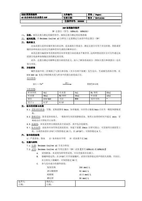
SOP标准操作程序TP 总蛋白(货号:OSR6132,OSR6232)一、目的:规范总蛋白测定的操作程序,确保总蛋白测定的结果准确二、适用范围:在Beckman Coulter AU分析仪上定量测定人血清中的总蛋白(TP)三、临床意义总血清蛋白是所有循环蛋白的总和,是血液的主要成分。
测定总蛋白可用于涉及肝脏,肾脏或骨髓的各种疾病以及其它代谢和营养失调的诊断和治疗。
血清总蛋白偏离参考范围表明存在异常蛋白血症或水平衡异常。
这两种情况的区分可另外通过血清蛋白电泳和血细胞比容的测定来实现。
此外,总蛋白测定对解释总蛋白浓度的意义,深入了解各组成部分(例如白蛋白和球蛋白)也有很大用处。
四、方法原理碱性溶液中的二价铜离子与蛋白和多肽(至少含两个肽键)发生反应,生成紫色的络合物。
在540/660 nm 处复合物的吸光度与样本中的蛋白浓度成正比。
反应原理:五、标本的采集与处理5.1.受检者的准备:空腹,采集前静坐5min,如有输液,应在停止输液3min后在另一侧肢体静脉采集。
5.2.静脉采血:除非是卧床病人,一般取坐位从肘部静脉采血,使用止血带的时间不超过1min,穿刺成功后立即松开止血带。
5.3.抗凝剂:本室采用带分离胶的真空采血管,其中包含促凝剂。
5.4.标本处理:血标本应该尽快送到实验室,室温下放置20min后即可离心,可直接用分离胶管上机。
分离的血清在2-8℃可保持稳定28天;在15-25℃,可保持稳定6天。
六、标本拒收标准1)严重溶血、脂血 2)标本标识不明 3)采血量不足2ml七、仪器与材料7.1.仪器:Beckman Coulter AU 生化分析仪7.2.试剂:Beckman Coulter AU专用总蛋白(TP)试剂【货号OSR6132或OSR6232】A.试剂准备:本试剂为即用型试剂,可以直接放在仪器上。
B.储藏和稳定性:在2-25℃不开封储藏时,试剂可保持稳定到声明的失效期;开封后,在分析仪上储藏时,可保持稳定30天C.参与反应成分的最终浓度:氢氧化钠 200 mmol/L酒石酸钠钾 32 mmol/L硫酸铜 18.8 mmol/L碘化钾 30 mmol/LD.此试剂作为体外诊断用;不要入口,吞下有害;如果溅入眼睛,请立即用大量清水冲洗,然后就医;避免接触皮肤,带上适当的手套;必须将试剂及其容器作为有害废物处理带上适当的手套;必须将试剂及其容器作为有害废物处理。
电信tp路由器默认密码规则摘要:1.电信TP路由器简介2.电信TP路由器默认密码规则3.修改电信TP路由器密码的方法4.增强电信TP路由器安全性的建议正文:【电信TP路由器简介】电信TP路由器,即中国电信提供的宽带路由器,是用户在办理宽带业务时常见的设备。
它可以让多个设备通过一个网络接口连接到互联网,方便用户在家庭或企业环境中使用。
这类路由器通常具有有线和无线网络功能,支持WAN(广域网)和LAN(局域网)连接。
【电信TP路由器默认密码规则】电信TP路由器的默认密码规则通常如下:- 用户名:admin- 密码:admin请注意,这个密码是出厂时的默认设置,为了保障网络安全,建议用户在首次使用时立即进行修改。
【修改电信TP路由器密码的方法】1.打开浏览器,输入路由器的IP地址,一般为192.168.1.1或192.168.0.1,进入路由器管理界面。
2.输入用户名和密码,默认用户名为admin,密码为admin。
3.在路由器管理界面,找到“用户管理”或“账户管理”选项,修改用户名和密码。
4.为了安全起见,建议使用复杂密码,包括字母、数字和特殊字符,避免使用过于简单的密码。
【增强电信TP路由器安全性的建议】1.修改默认管理员密码:如上所述,修改路由器管理员密码为复杂且不易被猜测的密码,以防止被恶意攻击。
2.启用WPA2加密:在路由器设置中,启用WPA2或更高级别的无线加密协议,以保护无线网络不被破解。
3.限制设备访问:在路由器管理界面,限制允许访问路由器的设备列表,避免陌生人接入网络。
4.关闭DHCP功能:如果不需要自动分配IP地址,可以关闭DHCP功能,以减少攻击面。
5.定期更新路由器固件:定期查看路由器厂商官网,更新路由器固件,修复已知的安全漏洞。
总之,电信TP路由器的默认密码为admin/admin,为了网络安全,建议用户在首次使用时立即修改。
端口号对应的协议篇一:常用协议对应的端口号标题:常用协议对应的端口号由Anonymous 于星期日, 04/01/2007 - 01:28 发表DHCP:服务器端的端口号是67DHCP:客户机端的端口号是68POP3:POP3仅仅是接收协议,POP3客户端使用SMTP向服务器发送邮件。
POP3所用的端口号是110。
SMTP:端口号是25。
SMTP真正关心的不是邮件如何被传送,而只关心邮件是否能顺利到达目的地。
SMTP具有健壮的邮件处理特性,这种特性允许邮件依据一定标准自动路由,SMTP具有当邮件地址不存在时立即通知用户的能力,并且具有在一定时间内将不可传输的邮件返回发送方的特点。
Telnet:端口号是23。
Telnet是一种最老的Internet应用,起源于ARPNET。
它的名字是“电信网络协议(Telecommunication Network Protocol)”的缩写。
FTP:FTP使用的端口有20和21。
20端口用于数据传输,21端口用于控制信令的传输,控制信息和数据能够同时传输,这是FTP的特殊这处。
FTP采用的是TCP连接。
TFTP:端口号69,使用的是UDP 的连接。
端口号的作用及常见端口号用途说明IP协议是由TCP、UDP、ARP、ICMP 等一系列子协议组成的。
其中,主要用来做传输数据使用的是TCP和UDP协议。
在TCP和UDP协议中,都有端口号的概念存在。
端口号的作用,主要是区分服务类别和在同一时间进行多个会话。
举例来说,有主机A需要对外提供FTP和WWW两种服务,如果没有端口号存在的话,这两种服务是无法区分的。
实际上,当网络上某主机B需要访问A的FTP服务时,就要指定目的端口号为21;当需要访问A的WWW服务时,则需要将目的端口号设为80,这时A 根据B访问的端口号,就可以区分B的两种不同请求。
这就是端口号区分服务类别的作用。
再举个例子:主机A需要同时下载网络上某FTP服务器B上的两个文件,那么A需要与B同时建立两个会话,而这两个传输会话就是靠源端口号来区分的。
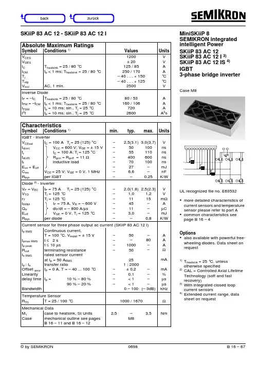
Absolute Maximum RatingsSymbol Conditions 1)Values Units V CES V GES I C I CM T j T stg V isolT heatsink = 25 / 80 °Ct p < 1 ms; T heatsink = 25 / 80 °C AC, 1 min.1200± 20125 / 85250 / 170– 40 . . . + 150– 40 . . . + 1252500V V A A °C °C V Inverse Diode I F = –I C I FM = –I CM I FSMI 2tT heatsink = 25 / 80 °Ct p < 1 ms; T heatsink = 25 / 80 °Ct p = 10 ms; sin., T j = 25 °C t p = 10 ms; sin., T j = 25 °C 80 / 53160 / 1067202600A A A A 2sCharacteristicsSymbol Conditions 1)min.typ.max.UnitsIGBT - InverterV CEsatt d(on)t rt d(off)t fE on + E off C ies R thjhI C = 100 A T j = 25 (125) °C V CC = 600 V; V GE = ± 15 V I C = 100 A; T j = 125 °C R gon = R goff = 11 Ωinductive load V CE = 25 V; V GE = 0 V, 1 MHzper IGBT ––––––––2,5(3,1)505540070276,6–3,0(3,7)100110600100––0,25V ns ns ns ns mJ nF K/W Diode 2) - InverterV F = V EC V TOr TI RRMQ rrE offR thjhI F = 75 A T j = 25 (125) °CT j = 125 °C T j = 125 °C I F = 75 A, V R = – 600 V di F /dt = – 800 A/µs V GE = 0 V, T j = 125 °C per diode –––––––2,0(1,8)1,01145113,0–2,5(2.3)1,215–––0,8V V m ΩA µC mJ K/W Current sensor for three phase output ac current (SKiiP 83 AC 12 I)I p RMS I pmax RMSI p peakR outI s RMSI p : I s Offset error Linearitydelay time BandwidthContinuous current,T = 100 °C, V suppl = ± 15 Vt ≤ 2 s t ≤ 10 µs terminating resistance rated sensor current at I p = 50 A RMStransfer ratioI P = 0 A, T = – 40 ... 100 °CI P =10 % – 80 %90 % – 20 %––––––––50–100050251 : 2000± 0,20,1< 1< 10 – 100–80––––––(– 3dB)A A A ΩmA mA %µs µs kHz Temperature SensorR TS T = 25 / 100 °C1000 / 1670ΩMechanical DataM 1Case case to heatsink, SI Units mechanical outline see pagesB 16 – 11 and B 16 – 122,5–M83,5NmSKiiP 83 AC 12 - SKiiP 83 AC 12 I MiniSKiiP 8SEMIKRON integrated intelligent Power SKiiP 83 AC 12SKiiP 83 AC 12 I 3)SKiiP 83 AC 12 IS 4)IGBT3-phase bridge inverterCase M8UL recognized file no. E63532•more detailed characteristics ofcurrent sensors and temperature sensor please refer to part A •common characteristics see page B 16 – 4Options•also available with powerful free-wheeling diodes. Data sheet on request1)T heatsink = 25 °C, unless otherwise specified2)CAL = Controlled Axial Lifetime Technology (soft and fast recovery)3)With integrated closed loop current sensors4)Extended current range, data sheet on request~~~0408012016002001234517V13V15V 11V 9V7VI C [A]V CE [V]83AC120104080120160200123459V7V13V15V 17V11V I C [A]83AC1202V CE [V]02468101214161820600V800VV GE [V]83AC1205Q G [nC]200400600800Fig. 3Turn-on /-off energy = f (I C )Fig. 4Turn-on /-off energy = f (R G )I Cpuls = 100 AV GE = 0 V f = 1 MHzFig. 1Typ. output characteristic, t p = 80 µs; 25 °C Fig. 2Typ. output characteristic, t p = 80 µs; 125 °CFig. 5Typ. gate charge characteristic Fig. 6Typ. capacitances vs. V CE T j = 125 °C V CE = 600 V V GE = ± 15 V I C = 100 AT j = 125 °C V CE = 600 V V GE = ± 15 V R G = 11 ΩT j = ≤ 150 °C V GE = ± 15 V t sc = ≤ 10 µs L ext < 25 nHT j = ≤ 150 °C V GE = ± 15 VT j = 150 °C V GE = ≥ 15 VFig. 9Turn-off safe operating area (RBSOA) of the IGBT Fig. 10Safe operating area at short circuit of the IGBTFig. 7Rated current of the IGBT I Cop / I C = f (T h)00.20.40.60.81.01.2255075100125150I Cop /I C Mini1207T h [°C]00,511,522,550010001500I Cpuls /I C Mini1209V CE [V]02468101250010001500Note:*Allowed nu mbers of short ci r cuit:<1000*Time between short circuit:>1sI Csc /I CN Mini1210V CE [V]Fig. 11Typ. freewheeling diode forward characteristic Fig. 12Forward characteristic of the input bridge diode MiniSKiiP 1200 VMiniSKiiP 8Inverter part SKiiP 82 AC 06 ...SKiiP 83 AC 06 ...SKiiP 81 AC 12 ...SKiiP 82 AC 12 ...SKiiP 83 AC 12 ...Circuit Case M8Note:The current sensors areavailable only by option IMiniSKiiP 8 Inverter partSKiiP 82 AC 06 ... SKiiP 83 AC 06 ... SKiiP 81 AC 12 ... SKiiP 82 AC 12 ... SKiiP 83 AC 12 ...Case M8Layout and connections for thecustomer’s printed circuit boardpin connection optional1T+2T-3~1ET1CB14GB15GT16–EB1EB2EB37+CT1CT2CT38GB29GT210~2ET2CB211+CT1CT2CT312–EB1EB2EB313GT314~3ET3CB315GB316K1 for ~1X17K2 for ~1X18S1 for ~1X19S2 for ~1X20K1 for ~2X21K2 for ~2X22S1 for ~2X23S2 for ~2X24K1 for ~3X25K2 for ~3X26S1 for ~3X27S2 for ~3X。


声明Copyright © 2012 深圳市普联技术有限公司版权所有,保留所有权利未经深圳市普联技术有限公司明确书面许可,任何单位或个人不得擅自仿制、复制、誊抄或转译本书部分或全部内容。
不得以任何形式或任何方式(电子、机械、影印、录制或其他可能的方式)进行商品传播或用于任何商业、赢利目的。
为深圳市普联技术有限公司注册商标。
本文档提及的其他所有商标或注册商标,由各自的所有人拥有。
本手册所提到的产品规格和资讯仅供参考,如有内容更新,恕不另行通知。
除非有特殊约定,本手册仅作为使用指导,本手册中的所有陈述、信息等均不构成任何形式的担保。
目录第一章产品概述 (1)1.1产品简介 (1)1.2主要特性 (2)第二章硬件描述 (3)2.1面板布置 (3)2.1.1前面板 (3)2.1.2后面板 (4)2.2复位 (5)2.3系统需求 (5)2.4安装环境 (5)2.5硬件连接 (6)第三章快速安装指南 (7)3.1建立正确的网络设置 (7)3.2快速安装指南 (8)第四章配置指南 (14)4.1启动和登录 (14)4.2运行状态 (14)4.3设置向导 (16)4.4网络参数 (16)4.4.1WAN口设置 (16)4.4.2以太网接入设置 (23)4.4.3分组设置 (29)4.4.4LAN口设置 (30)4.4.5MAC地址克隆 (32)4.4.6应用层网关设置 (33)4.4.7DSL参数设置 (33)4.4.8PVC自动检测 (34)4.5DHCP服务器 (35)4.5.1DHCP服务设置 (35)4.5.2客户端列表 (36)4.5.3静态地址分配 (36)4.5.4条件地址池设置 (38)4.6无线设置 (39)4.6.1基本设置 (39)4.6.2QSS安全设置 (41)4.6.3无线安全设置 (53)4.6.4无线MAC地址过滤 (55)4.6.5无线高级设置 (57)4.6.6无线主机状态 (58)4.7IPTV设置 (58)4.8路由功能 (59)4.8.1默认路由设置 (59)4.8.2静态路由表 (60)4.8.3RIP设置 (61)4.9转发规则 (62)4.9.1虚拟服务器 (62)4.9.2特殊应用程序 (64)4.9.3DMZ主机 (65)4.9.4UPnP设置 (66)4.10家长控制 (67)4.11防火墙 (69)4.11.1规则管理 (69)4.11.2内网主机 (72)4.11.3外网主机 (73)4.11.4日程计划 (75)4.11.5攻击防护 (76)4.12IP带宽控制 (77)4.12.1控制设置 (77)4.12.2控制规则 (78)4.13IP与MAC绑定 (80)4.13.1静态ARP绑定设置 (80)4.13.2ARP映射表 (81)4.14动态DNS (82)4.15诊断工具 (83)4.16系统管理 (84)4.16.1系统日志 (85)4.16.2时间设置 (85)4.16.3管理控制 (86)4.16.4备份和载入配置 (88)4.16.5恢复出厂设置 (90)4.16.6软件升级 (90)4.16.7重启路由器 (91)附录A FAQ (92)附录B IE浏览器设置 (96)附录C规格参数 (98)产品概述第一章1.1 产品简介首先感谢您购买TD-W89841N ADSL无线路由一体机!TD-W89841N ADSL无线路由一体机是专为满足小型企业、办公室和家庭办公室的无线上网需要而设计的,它功能实用、性能优越、易于管理。
TP中图分类号TP 自动化技术、计算机技术[TP-9] 自动化技术经济TP1 自动化根底理论TP11 自动化系统理论TP13 自动控制理论TP14 自动信息理论TP15 自动模拟理论〔自动仿真理论〕TP17 开关电路理论TP18 人工智能理论TP181 自动推理、机器学习TP182 专家系统、常识工程TP183 人工神经网络与计算TP2 自动化技术及设备TP20 一般性问题TP202 设计、性能阐发与综合TP202+.1 可靠性、不变性、寿命TP202+.2 精确性、误差TP202+.3 灵敏度TP202+.4 随机过程、随机信号TP202+.5 过渡过程TP202+.7 最正确化、自适应性TP203 布局、构造TP204 材料TP205 制造、装配、改装TP206 调整、测试TP206+.1 试验、测试技术与方法TP206+.3 故障预测、诊断与排除TP207 检修、维护TP21/27 各种自动化元件、部件、装置、系统 TP21 自动化元件、部件TP211 一般自动化元件、部件TP211+.1 无触点元件、部件TP211+.2 机械元件、部件TP211+.3 流体元件、部件TP211+.31 液压元件、部件TP211+.32 气压元件、部件TP211+.4 机电元件、部件TP211+.5 电子元件、部件TP211+.51 半导体元件、部件TP211+.53 磁性元件、部件TP211+.6 光电元件、部件TP211+.7 射线元件、部件TP212/217 各种自动化器件、自动化仪表 TP212 发送器〔变换器〕、传感器TP212.1 物理传感器TP212.11 温度传感器TP212.12 机械量传感器TP212.13 磁性传感器TP212.14 光传感器TP212.2 化学传感器TP212.3 生物传感器、医学传感器TP212.6 智能化传感器TP212.9 传感器的应用TP213 分配器、配电器TP214 调节器、调节阀TP214+.1 线性调节器TP214+.2 非线性调节器TP214+.3 比例调节器〔有差调节器〕 TP214+.4 积分调节器〔无差调节器〕 TP214+.5 比例积分调节器TP214+.6 比例微分调节器TP214+.7 程序调节器TP214+.8 最正确调节器TP214+.9 极值调节器TP215 传动装置〔执行机构〕TP216 自动检测仪器、仪表TP216+.1 自动测量仪表TP216+.2 自动记录和指示仪表TP216+.3 自动阐发器TP216+.4 计算仪器TP217 校正元件、校正装置TP217+.1 无源校正元件TP217+.2 交流校正元件TP217+.3 有源校正元件TP23 自动扮装置与设备TP24 机器人技术TP241 机械手TP241.2 工业机械手TP241.3 专用机械手TP242 机器人TP242.2 工业机器人TP242.3 专用机器人TP242.6 智能机器人TP242.6+1 机器人触觉TP242.6+2 机器人视觉TP242.6+3 机器人听觉TP242.6+4 机器人嗅觉TP249 应用TP27 自动化系统TP271 一般自动化系统TP271+.1 无触点系统TP271+.2 机械系统TP271+.3 流体系统TP271+.31 液压系统TP271+.32 气压系统TP271+.4 机电系统TP271+.5 电子系统TP271+.6 持续系统TP271+.61 持续线性系统TP271+.62 持续非线性系统TP271+.7 变参数系统TP271+.71 线性变参数系统TP271+.72 非线性变参数系统TP271+.73 断续变参数系统TP271+.74 随机变参数系统TP271+.8 不持续〔离散、断续〕系统TP271+.81 采样〔脉冲〕系统TP271+.82 数字和程序系统TP271+.83 继电器系统TP271+.9 反应系统TP272/278 各种自动化系统TP272 自动调节、自动调节系统TP273 自动控制、自动控制系统TP273+.1 最正确控制、最正确控制系统TP273+.2 自适应〔自整定〕控制、自适应控制〔自整定〕系统 TP273+.21 特性自适应控制系统TP273+.22 学习控制系统、自行组织系统TP273+.23 极值系统〔自寻最正确系统〕TP273+.24 自整定系统TP273+.3 复合控制、复合控制系统TP273+.4 模糊控制、模糊控制系统TP273+.5 计算机控制、计算机控制系统TP274 数据处置、数据处置系统TP274+.1 自动记录和指示系统TP274+.2 数据收集和处置系统TP274+.3 自动分类与质量查抄系统TP274+.4 集中检测与巡回检测系统TP274+.5 采用各种新技术的自动检测系统TP274+.51 放射线检测及其设备TP274+.52 红外线检测及其设备TP274+.53 超声波检测及其设备TP275 自动随动、自动随动系统TP276 自动拖动、自动拖动系统TP277 监视、报警、故障诊断系统TP278 自动出产作业线TP29 自动化技术在各方面的应用TP3 计算技术、计算机技术TP3-0 计算机理论与方法TP3-05 计算机与其他学科的关系TP30 一般性问题TP301 理论、方法TP301.1 自动机理论TP301.2 形式语言理论TP301.4 可计算性理论TP301.5 计算复杂性理论TP301.6 算法理论TP302 设计与性能阐发TP302.1 总体设计、系统设计TP302.2 逻辑设计TP302.4 制图TP302.7 性能阐发、功能阐发TP302.8 容错技术TP303 总体布局、系统布局TP303+.1 元件TP303+.2 插件、机架TP303+.3 电源系统TP304 材料TP305 制造、装配、改装TP305+.1 微小型化工艺TP305+.2 防潮、防霉、防腐工艺TP306 调整、测试、校验TP306+.2 调整、测试方法TP306+.3 故障诊断与排除TP307 检修、维护TP308 机房TP309 平安保密TP309.1 计算机设备平安TP309.2 数据平安TP309.3 数据备份与恢复TP309.5 计算机病毒与防治TP309.7 加密与解密TP31 计算机软件TP311 程序设计、软件工程TP311.1 程序设计TP311.11 程序设计方法TP311.12 数据布局TP311.13 数据库理论与系统TP311.131 数据库理论TP311.132 数据库系统:按类型分TP311.132.1 层次数据库TP311.132.2 网状数据库TP311.132.3 关系数据库TP311.132.4 面向对象的数据库TP311.133.1 分布式数据库TP311.133.2 并行数据库TP311.134.1 模糊数据库TP311.134.3 多媒体数据库TP311.135.1 文献型数据库TP311.135.3 事实型数据库TP311.135.4 超文本数据库TP311.138 数据库系统:按系统名称分 TP311.5 软件工程TP311.51 程序设计自动化TP311.52 软件开发TP311.53 软件维护TP311.54 软件移植TP311.56 软件东西、东西软件TP312 程序语言、算法语言TP313 汇编程序TP314 编译程序、解释程序TP315 办理程序、办理系统TP316 操作系统TP316.1/.5 操作系统:按类型分TP316.1 分时操作系统TP316.2 实时操作系统TP316.3 批处置TP316.4 分布式操作系统、并行式操作系统 TP316.5 多媒体操作系统TP316.6/.8 操作系统:按名称分TP316.6 DOS操作系统TP316.7 Windows操作系统TP316.8 网络操作系统TP316.81 UNIX操作系统TP316.82 XENIX操作系统TP316.83 NOVELL操作系统TP316.84 OS/2操作系统TP316.86 WindowsNT操作系统TP316.89 其他TP316.9 中文操作系统TP317 程序包〔应用软件〕TP317.1 办公自动化系统TP317.2 文字处置软件TP317.3 表处置软件TP317.4 图像处置软件TP319 专用应用软件TP32 一般计算器和计算机TP321 非电子计算机TP321+.1 求积仪、曲线仪TP321+.2 积分器TP321+.21 机械积分器TP321+.22 液压积分器TP321+.23 气压积分器TP321+.24 电气、机电积分器TP321+.3 手动计算机TP321+.5 电动计算机TP322 阐发计算机〔穿孔卡片计算机〕TP322+.1 穿孔机TP322+.2 验孔机TP322+.3 分类机TP322+.5 制表机TP323 电子计算器TP323+.1 台式计算器TP323+.2 袖珍计算器TP33/38 各种电子计算机TP33 电子数字计算机〔不持续作用电子计算机〕 TP331 根本电路TP331.1 逻辑电路TP331.1+1 集成化逻辑电路TP331.1+3 金属-氧化物-半导体管逻辑电路 TP331.2 数字电路TP332 运算器和控制器(CPU)TP332.1 逻辑部件TP332.1+1 存放器TP332.1+2 计数器TP332.2 运算器TP332.2+1 加、减法器TP332.2+2 乘、除法器TP332.3 控制器、控制台TP333 存贮器TP333.1 内存贮器〔主存贮器〕总论TP333.2 外存贮器〔辅助存贮器〕总论TP333.3 磁存贮器及其驱动器TP333.3+1 磁芯存贮器TP333.3+11 单孔磁芯存贮器TP333.3+12 多孔磁芯存贮器TP333.3+2 磁薄膜存贮器TP333.3+21 平面磁薄膜存贮器TP333.3+3 磁泡存贮器TP333.3+4 磁鼓存贮器TP333.3+5 磁盘存贮器TP333.3+6 磁带存贮器TP333.3+7 电磁继电器存贮器TP333.4 光存贮器及其驱动器TP333.4+1 磁光存贮器TP333.4+2 全息存贮器TP333.4+3 激光存贮器TP333.5 半导体集成电路存贮器TP333.5+1 双极性型半导体存贮器TP333.5+2 金属-氧化物-半导体(MOS)存贮器 TP333.5+3 电荷耦合型存贮器TP333.6 超导体存贮器TP333.7 只读(ROM)存贮器TP333.8 随机存取存贮器TP333.93 交换器TP333.95 延迟线存贮器TP333.95+1 水银柱延迟线存贮器TP333.95+3 石英晶体延迟线存贮器TP333.95+5 磁滞伸缩延迟线存贮器TP333.96 虚拟存贮器TP334 外部设备TP334.1/.4 各种外部设备TP334.1 终端设备TP334.2 输入设备TP334.2+1 图形输入设备TP334.2+2 图像输入设备TP334.2+3 文字与数字输入设备TP334.2+4 语音输入设备TP334.3 输出设备TP334.4 输入输出控制器[TP334.5] 外存储器TP334.7 接口装置、插件TP334.8 打印装置TP334.8+1 针式打印机TP334.8+2 热敏打印机TP334.8+3 喷墨打印机TP334.8+4 激光打印机TP334.8+8 各种用途打印机TP334.9 其他TP335 信息转换及其设备TP335+.1 模拟-数字转换设备TP335+.2 文字-代码转换设备TP335+.3 图形-代码转换设备TP335+.4 数字-模拟转换设备TP336 总线、通道TP337 仿真器TP338 各种电子数字计算机[TP338.1] 微型计算机TP338.2 小型计算机TP338.3 中型计算机TP338.4 大型、巨型计算机TP338.6 并行计算机TP338.7 阵列式计算机TP338.8 分布式计算机TP34 电子模拟计算机(持续作用电子计算机) TP342 运算放大器和控制器TP342+.1 运算放大器TP342+.2 运算器TP342+.21 加、减法器TP342+.22 乘、除法器TP342+.23 平方器、开方器TP342+.25 积分器、微分器TP342+.3 控制器TP343 存贮器TP344 输入器、输出器TP346 函数发生器TP347 延时器TP348 各种电子模拟计算机TP348+.1 微分阐发器与增量计算机TP348+.2 直流电子模拟计算机TP348+.3 交流电子模拟计算机TP35 混合电子计算机TP352 数字-模拟计算机TP352+.1 数字微分阐发器TP353 模拟-数字计算机TP36 微型计算机TP368 各种微型计算机TP368.1 微处置机TP368.2 单板微型计算机TP368.3 个人计算机TP368.32 笔记本计算机TP368.33 超微型计算机TP368.5 效劳器、工作站TP368.6 网络计算机(NC)TP37 多媒体技术与多媒体计算机TP38 其他计算机TP381 激光计算机TP382 射流计算机TP383 超导计算机TP384 分子计算机TP387 第五代计算机TP389.1 人工神经网络计算机TP39 计算机的应用TP391 信息处置(信息加工)TP391.1 文字信息处置[TP391.11] 汉字信息编码TP391.12 汉字处置系统TP391.13 表格处置系统TP391.14 文字录入技术TP391.2 翻译机TP391.3 检索机TP391.4 模式识别与装置TP391.41 图像识别及其装置[TP391.42] 声音识别及其装置TP391.43 文字识别及其装置TP391.44 光模式识别及其装置TP391.5 诊断机TP391.6 教学机、学习机TP391.7 机器辅助技术TP391.72 机器辅助设计〔CAD〕、辅助制图 TP391.73 机器辅助技术制造(CAM)TP391.75 机器辅助计算(CAC)TP391.76 机器辅助测试(CAT)TP391.77 机器辅助阐发(CAA)TP391.8 控制机TP391.9 计算机仿真TP392 各种专用数据库TP393 计算机网络TP393.0 一般性问题TP393.01 计算机网络理论TP393.02 计算机网络布局与设计TP393.03 网络互连技术[TP393.04] 通信规程、通信协议[TP393.05] 网络设备TP393.06 计算机网络测试、运行TP393.07 计算机网络办理TP393.08 计算机网络平安TP393.09 计算机网络应用程序TP393.092 网络浏览器TP393.093 文件传送程序(FTP)TP393.094 长途登录(Telnet)TP393.098 电子邮件(E-mail)TP393.1/.4 各种计算机网TP393.1 局域网〔LAN〕、城域网〔MAN〕TP393.11 以太网TP393.12 令牌网TP393.13 DQDB网〔分布队列双总线网络〕 TP393.14 FDDI网〔高速光纤环网〕TP393.15 ATM局域网[TP393.17] 无线局域网TP393.18 校园网、企业网〔Intranet〕TP393.2 广域网〔WAN〕{TP393.3} 洲际网络TP393.4 国际互联网TP399 在其他方面的应用TP6 射流技术〔流控技术〕TP60 一般性问题TP601 理论、研究TP602 设计及性能阐发TP602+.1 静态特性TP602+.2 动态特性TP603 布局、构造TP604 材料TP605 制造、装配TP606 调整、测试TP606+.1 静态测试TP606+.2 动态测试TP607 检修、维护TP61/67 各种射流装置TP61 射流元件TP61+1 有源射流元件TP61+2 无源射流元件TP61+3 数字射流元件〔逻辑元件〕TP61+3.1 附壁式射流元件TP61+3.2 紊流式射流元件〔紊流放大器〕TP61+3.3 动量交换式元件TP61+4 比例射流元件〔模拟元件〕TP61+4.1 对冲元件TP61+4.3 涡流元件TP61+5 液压式射流元件TP62 射流附件TP62+1 升压器TP62+2 转换器TP62+3 延时器TP62+4 抽负器TP63 检测发信装置TP64 执行机构TP65 动力源TP65+1 气源净化系统TP65+2 气源附件TP65+2.1 过滤器TP65+2.2 减压阀TP65+2.3 定值器TP66 射流控制线路TP67 射流自动控制系统TP69 射流技术的应用TP7 遥感技术TP70 一般性问题TP701 理论TP702 设计和性能阐发TP703 布局TP704 材料TP705 制造、装配TP706 调整、测试TP707 检修、维护TP72/75 各种遥感及装置TP72 遥感方式TP721 依传感器接受信号的来源分 TP721.1 被动式遥感TP721.2 主动式遥感TP722 依探测的波长范围分TP722.3 紫外遥感TP722.4 可见光遥感TP722.5 红外遥感TP722.6 微波遥感TP73 探测仪器及系统TP731 多光谱扫描仪TP732 遥感传感器TP732.1 微波遥感传感器TP732.2 红外遥感传感器TP733 反束光导管摄像机TP75 遥感图像的解译、识别与处置 TP751 图像处置方法TP751.1 数字处置TP751.2 光学处置TP752 图像处置设备TP752.1 数字处置设备TP752.2 光学处置设备TP753 图像解释、判读TP79 遥感技术的应用TP8 远动技术TP80 一般性问题TP801 理论、研究TP802 设计和性能阐发TP802+.1 可靠性、不变性、寿命TP802+.2 精确性、误差TP802+.3 灵敏度TP802+.4 远动信号、信号发射、接收及转换TP802+.5 作用距离TP802+.6 干扰〔噪声〕、抗干扰TP802+.7 最正确化、自适应性TP802+.8 信道划分TP803 布局TP804 材料TP805 制造、装配TP806 调整、测试TP806+.1 试验、测试技术与方法TP806+.3 故障预测、诊断与排除TP807 检修、维护TP81/87 各种远动装置及系统[TP81] 远动元件、部件TP83 远动扮装置TP84 长途信道TP84+1 有线信道TP84+2 无线电中继信道TP87 远动化系统TP871 远距离调节、远距离调节系统TP872 远距离控制和信号、远距离控制和信号系统 TP872+.1 近作用的遥控系统TP872+.2 断续遥控系统TP872+.21 频率制TP872+.22 时间制TP872+.3 持续遥控系统TP872+.31 频率制TP872+.32 时间制TP872+.33 脉码制TP873 远距离测量、远距离测量系统TP873+.1 单路遥测系统TP873+.11 频率制TP873+.12 时间制TP873+.13 脉码制TP873+.14 增量制TP873+.2 多路遥测系统TP873+.21 频率划分制TP873+.22 时间划分制TP873+.23 脉码划分制TP89 远动技术在各方面的应用内容总结。
专题:“蓝牙”也牙疼
李锋白
【期刊名称】《电脑知识与技术》
【年(卷),期】2000(000)0S4
【摘要】几个月来,我们常听到象蓝牙等无线技术将能实现所有移动和家庭设备
之间的通讯。
似乎每一个人都希望能够分享“无线革命”的一部分,都想得到使生活变得更容易的技术。
蓝牙技术将把我们带向何方呢?发生了什么?蓝牙是
一个短距离声音和数据交流规范。
蓝牙取自于丹麦蓝牙国王海罗得二世,他出生于大约公元 940年。
在现代,蓝牙更多的含义是有关当今那些北欧海盗及他们对市
场统治地位的需求。
蓝牙无线技术是由“蓝牙特别兴趣集团”( the Bluetooth Special Interest Group)对外公布的一项短距离通讯协议。
“蓝牙特别兴趣集团”有电信业、计算机业和网络业的领导厂商组成,他们是爱立信、 IBM、
【总页数】4页(P48-51)
【作者】李锋白
【作者单位】
【正文语种】中文
【中图分类】TP3
【相关文献】
1.牙疼不是病疼起来真“要命”冬季牙疼保健方法 [J], ;
2.应用蓝牙技术的未来超市--IBM论坛2003"零售行业信息化"专题采访 [J],
3.走近蓝牙认识蓝牙蓝牙耳机让无线更精彩 [J], 康健;
4.蓝牙(R)技术迈向802.11高速传输标准——蓝牙技术联盟发展高速蓝牙传输,满足市场高速需求 [J],
5.CSR蓝牙低功耗在蓝牙技术领域占据领先地位 BlueCore7是首个通过认证的蓝牙低功耗解决方案 [J],
因版权原因,仅展示原文概要,查看原文内容请购买。
TP 自动化技术、计算机技术TP1自动化基础理论TP2自动化技术及设备TP20 一般性问题TP21 自动化元件、部件TP23 自动化装置与设备TP24 机器人技术TP27 自动化系统TP29 自动化技术在各方面的应用TP3计算技术、计算机技术TP30 一般性问题TP31 计算机软件TP32 一般计算器和计算机TP33 电子数字计算机(不连续作用电子计算机)TP34 电子模拟计算机(连续作用电子计算机)TP35 混合电子计算机TP36 微型计算机TP37 多媒体技术与多媒体计算机TP38 其他计算机TP39 计算机的应用TP6射流技术(流控技术)TP7遥感技术TP8远动技术TN 无线电电子学、电信技术TN91 通信TN911 通信理论TN912 电声技术和语音信号处理TN913 有线通信、通信线路工程TN914 通信系统(传输系统)TN915 通信网O 数学O21 概率论与数理统计O22 运筹学O23 控制论、信息论(数学理论)O24 计算数学TP 自动化技术、计算机技术[TP-9] 自动化技术经济宜入F407.67。
TP1 自动化基础理论TP11 自动化系统理论人机系统、联机系统理论入此。
人工智能理论入TP18:系统理论入N94。
TP13 自动控制理论控制论在自动化中的应用入此。
控制论的数学理论入O231;工程控制论入TB114.2。
TP14 自动信息理论信息理论在自动化中的应用入此。
总论信息论的著作入G201;信息论的数学理论入O236:数字信号处理入TN911.72。
TP15 自动模拟理论(自动仿真理论)模拟理论在自动化中的应用入此。
模拟理论入N032;数学模拟入O242.1;系统仿真入TP391.9。
TP17 开关电路理论自动继电线路原理入此。
TP18 人工智能理论智能模拟理论、智能控制理论入此。
智能语言、智能程序设计入TP31有关各类;智能机器人入TP242.6。
TP181 自动推理、机器学习TP182 专家系统、知识工程TP183 人工神经网络与计算人工神经网络计算机入TP389.1。
南京拓微集成电路有限公司DATASHEET
(TP83 升压系列)
DC/DC升压变换芯片—TP83系列
一、概述
TP83系列芯片是采用CMOS工艺制造的静态电流极低的VFM开关型DC/DC升压转换器。
该芯片由振荡器、VFM模式控制电路、Lx开关驱动晶体管、基准电压单元、误差比较放大器、电压采样电阻及V LX限幅电路等组成。
TP83系列升压转换器采用变频的方式,因此较国内外同类产品具有更低的纹波、更强的驱动能力、效率高等特点,应用时外围只需接三个元件(电感、电容及二极管各一个)。
输入电压最低0.8V,并且可以根据要求调整输出电压3V—6V可选。
二、芯片特性及主要参数
该设计产品TP83系列DC/DC升压转换器芯片在应用中具有优越的性能:
1.外接元件少:
需肖特基管、电感及电容各一个;外接元件建议选择: 低直流电阻电感20~220μH,钽电容47~200μF,肖特基二极管。
2.极低的静态电流:4uA
3.低噪声及低纹波:纹波典型值为100mV
4.驱动能力强:Vtyp=3.3V, Vin=1.0V时,Iout=100mA
Vtyp=3.3V, Vin=3.0V时,Iout=750mA
5.启动工作电压低:最大0.8V
6.高效率:85%(Typ)
7.封装体积小:SOT89,SOT23(窄体)
三、应用范围
TP83系列芯片适用于要求大驱动能力、低静态电流、低电磁辐射的电池供电设备:
1、电池供电设备的电源部分。
2、玩具、照相机、摄像机、PDA及手持电话等便携式设备的电源部分。
3、要求提供电压比电池所能提供电压高的设备的电源部分。
四、命名规则
内置MOS管命名:外置MOS管命名:
五、 芯片模型及引脚介绍
本设计芯片封装样式如下图,其引脚说明亦如下表所示
引脚说明:
Vss:接地引脚 Lx:开关引脚(或Ext 外置Tr) OUT:升压输出引脚
封装
PIN1 PIN2 PIN3 SOT89 Vss OUT Lx (Ext )
SOT23(窄体,见封装结构尺寸)
Vss Lx (Ext )
OUT
六、 极限参数
对地输入电压V IN 10V 输出电流Iout 800mA 功耗P d
SOT-23 0.25W
SOT-89
0.50 工作温度T A -40℃~145℃ 导线焊接温度(10秒) 260℃
七、 工作原理
利用电感对能量的存储,并通过其与输入端电源共同的泄放作用,从而获得高于输入电压的输出电压。
如图:
八、电性能参数
其主要参数测试如下表:
测试条件:VIN=2.2V,Vss=0V,Iload=10mA,Topt= 25℃,Cout=100 µF(胆电容或使用100uF电解电容和0.1uF-1uF陶瓷电容并联),L= 47 µH(内阻0.1欧姆)。
有特别说明除外。
TP8330(电路见图一):
参数符号测试状态最小值典型值最大值单位输出电压V out 2.925 3.000 3.075 V
0.5 0.8 0.9 V
开启电压V start I L=1mA
V IN:0→0.98V
0.3 0.5 0.6 V
保持电压V hold I L=1mA
V IN:0.98→0V
无负载输入电流I IN1V IN=2.2V空载 6 10 25 µA
静态输入电流I IN2 2 4 8 µA
开关管导通电流I LX V LX=0.4V 450 mA
开关管漏电流I Lxleak V LX=6V 1 µA
振荡频率F OSC150 200 250 kHz
占空比Dty 80 %
效率η85 %
TP8333:
参数符号测试状态最小值典型值最大值单位输出电压V out 3.217 3.300 3.383 V
0.5 0.8 0.9 V
开启电压V start I L=1mA
V IN:0→0.98V
0.3 0.5 0.6 V
保持电压V hold I L=1mA
V IN:0.98→0V
无负载输入电流I IN1V IN=2.2V空载8 10 25 µA
静态输入电流I IN2 2 4 8 µA
开关管导通电流I LX V LX=0.4V 450 mA
开关管漏电流I Lxleak V LX=6V 1 µA
振荡频率F OSC150 200 250 kHz
占空比Dty 80 %
效率η85 %
TP8350:
参数符号测试状态最小值典型值最大值单位
输出电压V out 4.875 5.000 5.125 V
0.5 0.8 0.9 V
开启电压V start I L=1mA
V IN:0→0.98V
0.5 0.6 V
保持电压V hold I L=1mA
V IN:0.98→0V
无负载输入电流I IN1V IN=2.2V空载8 15 25 µA
静态输入电流I IN2 2 4 8 µA
开关管导通电流I LX V LX=0.4V 570 mA
开关管漏电流I Lxleak V LX=6V 1 µA
振荡频率F OSC150 200 250 kHz
占空比Dty 80 %
效率η85 %
TP8356X(电路见图二):
参数符号测试状态最小值典型值最大值单位输出电压V out 5.460 5.600 5.740 V
无负载输入电流I IN1V IN=2.2V空载8 15 25 µA
静态输入电流I IN2 1 4 8 µA
I EXT N V DS=0.4V 22 mA
CMOS驱动输出管
导通电流I EXT P V DS=-0.4V 20 mA
振荡频率F OSC150 200 250 kHz
占空比Dty 80 %
工作特性曲线如下:
测试条件:L=47uH(内阻0.1欧姆) Cout=100uF(胆电容或使用100uF电解电容和0.1uF-1uF陶瓷电容并联)
九、TP83系列升压芯片应用实例
典型应用电路:
L=47uH(内阻0.1ohm)、Cout=100uF电解电容并接0.1uF陶瓷电容、Diode为肖特基二极管TP8330典型应用电路(TP8350、TP8356电路见附件):
(测试输入电流时,输入电容Cin=47uF必须接入)
图一:TP8330典型应用电路
TP8356X典型应用电路(外置NMOS管为低阈值开启电压,例GE2300):
图二:TP8356X典型应用电路
升压/降压电路:
降压电路
注:以上电路中的启动电路
十、使用注意事项
外围电路对TP83系列升压转换芯片性能影响很大,需合理选择外部器件:
1) 外接电容值不宜小于47μF(电容值过小将导致输出纹波过大),同时要有良好的频率特性(最好使用钽电容或高频电容)。
此外,由于LX开关驱动晶体管关断时会产生一尖峰电压,电容的容压值至少为设计输出电压的3倍;(普通的铝电解电容ESR值过高,所以可选购专门应用于开关式DC/DC转换器的铝电解电容)。
2) 外接电感值要足够小以便即使在最低输入电压和最短的LX开关时间内能够存储足够的能量,同时,电感值又要足够大从而防止在最高输入电压和最长的LX开关时间时ILXMAX超出最大额定值。
此外,外接电感的直流阻抗要小、容流值要高且工作时不至于达到磁饱和。
3) 外接二极管宜选择具有较高切换速度的肖特基二极管。
4) 客户若驱动大电流负载(大于150mA),而纹波要求不高,则可以减小电感(22uH左右);
注意事项:
1)该芯片为驱动大负载而设计,所以外围元器件与芯片距离越小越好,连线越短越好。
特别是接到OUT 端的元器件应尽量减短与电容的连线长度;
2)特别建议使用钽电容;如果在芯片OUT和Vss两端并接电解电容时需要并接0.1-1µ的陶瓷电容。
3)Vss端应充分接地,否则芯片内部的零电位会随开关电流而变化,造成工作状态不稳定。
十一、封装结构尺寸图示
SOT-23(窄体)
附件:
内置MOS管TP8350、TP8356驱动大电流高效率方案
输入电源为锂电池(3.2v≤Vin≤4.2v)
1.驱动负载150mA≤Io≤500mA
(1)TP8350典型应用电路
锂电池输入条件下TP8350驱动大负载电路
建议各器件参数L=47uH(内阻<0.1ohm),Cin=47uF(实际应用中可不接该电容),Diode=1N5817\1N5818\1N5819,
Cout为20uF电解电容(或20uF胆电容串联0.5欧姆电阻)和0.1uF陶瓷电容并联。
驱动400mA负载下,效率高于80%
(2)TP8356典型应用电路
锂电池输入条件下TP8350驱动大负载电路
建议各器件参数L=100uH(内阻<0.1ohm),Cin=47uF(实际应用中可不接该电容),Diode=1N5817\1N5818\1N5819,
Cout为20uF电容(不分电解电容、胆电容)串联0.5欧姆电阻和0.1uF陶瓷电容并联。
驱动400mA负载下,效率高于80%
2.驱动负载Io<150mA时
TP8350、TP8356外围器件参数参照TP83规格书中典型应用电路的参数。
注意:TP8350、TP8356应用中陶瓷电容0.1uF~1uF必须接上,并且靠近芯片输出端。