光电检测技术英文
- 格式:doc
- 大小:280.50 KB
- 文档页数:13

大学课程专业名称中英文对照关键词:大学课程专业名称中英文对照工学ENGINEERING课程中文名称课程英文名称高等数理方法Advanced Mathematical Method弹塑性力学Elastic-Plastic Mechanics板壳理论Theory of Plate and Shell高等工程力学Advanced Engineering Mechanics板壳非线性力学Nonlinear Mechanics of Plate and Shell复合材料结构力学Structural Mechanics of Composite Material弹性元件的理论及设计Theory and Design of Elastic Element非线性振动Nonlinear Vibration高等土力学Advanced Soil Mechanics分析力学Analytic Mechanics 随机振动Random Vibration数值分析Numerical Analysis基础工程计算与分析Calculation and Analysis of Founda tion Engineering 结构动力学StructuralDynamics 实验力学Laboratory Mechanics 损伤与断裂Damage and Fracture 小波分析WaveletAnalysis 有限元与边界元分析方法Analytical Method of Finite Element and Boundary Element 最优化设计方法Optimal Design Method 弹性力学Elastic Mechanics 高层建筑基础Tall BuildingFoundation 动力学Dynanics 土的本构关系Soil Constitutive Relation 数学建模Mathe maticalModeling 现代通信理论与技术Emerging Communications Theory and Technology 数字信号处理Digital Signal Processing 网络理论与多媒体技术Multi-media and Network Technolog y 医用电子学Electronics for Medicine 计算微电子学Computational Microelectronics 集成电路材料和系统电子学Material and System Electronics for In tegrated Circuits 网络集成与大型数据库C omputerNetwork Integrating Technology and Large scale Database 现代数字系统Modern Di gital System微机应用系统设计Microcomputer Application Design 计算机网络新技术Modern Com puter NetworkTechnologies 网络信息系统Network Information System 图像传输与处理Image Tran smission andProcessing 图像编码理论Theory of Image Coding 遥感技术Remote Sensing Techni ques 虚拟仪器系统设计Design of Virtual Instrument System 生物医学信号处理技术Signal Processin g forBiology and Medicine 光纤光学Fiber Optics VLSI的EDA技术EDA Techniques for VLSI 电子系统的ASIC技术ASIC Design Technologies VLSI技术与检测方法VLSI Techniques & Its E xamination 专题阅读或专题研究The Special Subject Study 信息论Information Theory 半导体物理学Semiconductor Physics 通信原理Principle of Communication 现代数理逻辑Modern MathematicalLogic 算法分析与设计Analysis and Design of Algorithms 高级计算机网络Advanced ComputerNetworks 高级软件工程Advanced Software Engineering 数字图像处理Digital Image Processing 知识工程原理Principles of Knowledge Engineering 面向对象程序设计Object-Oriented Programming形式语言与自动机Formal Languages and Automata 人工智能程序设计Artificial Intelli genceProgramming 软件质量与测试Software Quality and Testing 大型数据库原理与高级开发技术Principles of Large-Scale Data-Bas e and Advanced Development Technology 自然智能与人工智能Natural Intelligence and Artificial Intelligence Unix操作系统分析Analysis of Unix Sys tem 计算机图形学Computer Graphics Internet与Intranet技术Internet and Intranet Technol ogy 多媒体技术Multimedia Technology 数据仓库技术与联机分析处理Data Warehouse and OLA P 程序设计方法学Methodology of Programming 计算机信息保密与安全Secrecy and Security of Compu ter Information电子商务Electronic Commerce 分布式系统与分布式处理Distributed Systems and Dis tributedProcessing 并行处理与并行程序设计Parallel Processing and Parallel Programming 模糊信息处理技术Fuzzy Information Processing Technology 人工神经网络及应用Artificial Intellige nce andIts Applications Unix编程环境Unix Programming Environment 计算机视觉Computer Vision 高级管理信息系统Advanced Management Information Systems 信息系统综合集成理论及方法Theory andMethodology of Information n System Integration 计算机科学研究新进展Advances in ComputerScience 离散数学Discrete Mathematics 操作系统Operating System 数据库原理Prin ciples ofDatabase 编译原理Principles of Compiler 程序设计语言Programming Language 数据结构DataStructure 计算机科学中的逻辑学Logic in Computer Science 面向对象系统分析与设计Object-Oriented System Analysis and Design 高等数值分析Advanced Numeric Analysis 人工智能技术Artificial Intelligence Technology 软计算理论及应用Theory and Application of Soft-C omputing逻辑程序设计与专家系统Logic Programming and Expert Systems 模式识别Pattern Recognition 软件测试技术Software Testing Technology 高级计算机网络与集成技术Advanced Comp uter Networksand Integration Technology 语音信号处理Speech Signal Processing 系统分析与软件工具SystemAnalysis and Software Tools 计算机仿真Computer Simulation 计算机控制Computer Control 图像通信技术Image Communication Technology 人工神经网络及应用Artificial Intelligence and ItsApplications 计算机技术研究新进展Advances in Computer Technology 环境生物学E nvironmentalBiology 水环境生态学模型Models of Water Quality 环境化学Environmental Chemistr y 环境生物技术Environmental Biotechnology 水域生态学Aquatic Ecology 环境工程Environmental Engineering环境科学研究方法Study Methodology of Environmental Science 藻类生理生态学Ecol ogicalPhysiology in Algae 水生动物生理生态学Physiological Ecology of Aquatic Animal 专业文献综述Review on Special Information 废水处理与回用Sewage Disposal and Re-use 生物医学材料学及实验Biomaterials and Experiments 现代测试分析Modern Testing Technology and Metho ds 生物材料结构与性能Structures and Properties of Biomaterials 计算机基础Computer Basis 医学信息学Medical Informatics 计算机汇编语言Computer Assembly Language 学科前沿讲座Le ctures onFrontiers of the Discipline 组织工程学Tissue Engineering 生物医学工程概论Introduc tion toBiomedical Engineering 高等生物化学Advanced Biochemistry 光学与统计物理Optics andStatistical Physics 图像分析Image Treatment 数据处理分析与建模Data Analysis an dConstituting Model 高级数据库Advanced Database 计算机网络Computer Network 多媒体技术Technology of Multimedia 软件工程Software Engineering 药物化学Pharmaceutical Chemistry 功能高分子Functional Polymer InternetIntranet(英)InternetIntranet 程序设计方法学M ethodsof Programming InternetIntranet 高分子化学与物理Polymeric Chemistry and Physics 医学电子学Medical Electronics 现代仪器分析Modern Instrumental Analysis 仪器分析实验Instru mentalAnalysis Experiment 食品添加剂Food Additives Technology 高级食品化学Advanced FoodChemistry 食品酶学Food Enzymology 现代科学前沿选论Literature on Advances of Modern Science波谱学Spectroscopy 波谱学实验Spectroscopic Experiment 食品贮运与包装Food Pa ckaging 液晶化学Liquid Crystal Chemistry 高等有机化学Advanced Organic Chemistry 功能性食品FunctionFoods 食品营养与卫生学Food Nutrition and Hygiene 食品生物技术Food Biotechnol ogy 食品研究与开发Food Research and Development 有机合成化学Synthetic Organic Chemistry 食品分离技术Food Separation Technique 精细化工装备Refinery Chemical Equipment 食品包装原理Principle ofFood Packaging 表面活性剂化学及应用Chemistry and Application of Surfactant 天然产物研究与开发Research and Development of Natural Products 食品工艺学Food Technology 生物化学Biochemistry 食品分析Food Analysis 食品机械与设备Food Machinery and Equipme nt理学SCIENCE-----------------------------------------------------------理学SCIENCE课程中文名称课程英文名称矩阵分析Matrix Analysis面向对象程序设计方法Design Methods of Object Oriented Program李代数Lie Algebra代数图论Algebraic Graph Theory代数几何(I)Algebraic Geometry(I)泛函分析Functional Analysis论文选读Study on Selected PapersHopf代数Hopf Algebra基础代数Fundamental Algebra交换代数Commutative Algebra代数几何Algebraic GeometryHopf代数与代数群量子群Hopf Algebra , Algebraic Group and Qua ntum Group量子群表示Representation of Quantum Groups网络算法与复杂性Network Algorithms and Complexity组合数学Combinatorial Mathematics代数学Algebra半群理论Semigroup Theory计算机图形学Computer Graphics图的对称性Graph Symmetry代数拓扑Algebraic Topology代数几何(II)Algebraic Geometry(II)微分几何Differential Geometry多复变函数Analytic Functions of Several Complex Variab les代数曲面Algebraic Surfaces高维代数簇Algebraic Varieties of Higher Dimension数理方程Mathematics and Physical Equation偏微分方程近代方法The Recent Methods of Partial Differential E quations激波理论The Theory of Shock Waves非线性双曲型守恒律解的存在性The Existence of Solutions for Non - linearHyperbolic Conservation Laws粘性守恒律解的稳定性Stability of Solutions for Viscous Conservation Laws微分方程数值解Numerical Methods for Differential Equations小波理论与应用Warelet Theory and Application非线性方程组的数值解法Numerical Methods for No-linear System s of Equations网络算法与复杂性Network Algorithms and ComplexityGraph Theory 60近世代数Modern Algebra高等量子力学Advanced Quantum Mechanics统计力学Statistical Mechanics固体理论Solid State Theory薄膜物理Thin Film Physics计算物理学Computational Physics量子场论Quantum Field Theory非线性物理导论Introduction to Nonlinear Physics固体磁性理论Theory of Magnetism in SolidC语言科学计算方法Scientific Computation Method in C功能材料原理与技术Principle and Technology of Functional Materials 超高真空科学与技术Science and Technology of Ultrahigh Vacuum 60 现代表面分析技术Modern Technology of Surface Analysis现代传感技术Modern Sensor Technology数学模型与计算机模拟Mathematical Models and Computer Simulations 计算物理谱方法Spectral Method in Computational Physics蒙特卡罗方法在统计物理中的应用Applications of the Monte Carlo Method inStatistical Physics理论物理Theoretical Physics固体物理Solid-State Physics近代物理实验Contemporary Physics Experiments计算物理基础Basics of Computational Physics真空与薄膜技术Vacuum & Thin Film Technology高等光学Advanced Optics量子光学与统计光学Quantum Optics and Statistical Optics光电子学与光电信息技术Optoelectronics and Optoelectronic Information Technology图像处理与分析Image Processing and Analysis光纤通信系统System of Fiber Communications计算机网络Computer Networks光电检测与信号处理Optoelectronic Detection and Processing物理光学与光电子技术实验Experiments for Physical Optics and Op toelectronic Technology非线性光学Nonlinear Optics集成光学Integrated Optics光子学器件原理与技术Principle and Technology of Photonics Devices物理光学与信息光子学实验Physical Optics & Information Photonics Experiments现代激光医学Modern Laser Medicine生物医学光子学Biomedicine Photonics激光医学临床实践Clinical Practice for Laser Medicine光纤通信网络Networks of Fiber Communications光接入网技术Technology of Light Access Network全光通信系统All-Optical Communication Systems计算机图形学Computer Graphics信息光学Information Optics光子学专题Special Topics on Photonics激光与近代光学Laser and Contemporary Optics光电子技术Photoelectronic Technique微机系统与接口Micro Computer System and Interface智能仪器Intelligent Instruments高等无机化学Advanced Inorganic Chemistry量子化学(含群论) Quantum Chemistry(including Group Theory)高等分析化学Advanced Analytical Chemistry高等有机化学Advanced Organic Chemistry现代科学前沿选论Literature on Frontiers of Modern Science and Technology激光化学Laser Chemistry激光光谱Laser Spectroscopy稀土化学Rare Earth Chemistry材料化学Material Chemistry生物无机化学导论Bioinorganic Chemistry配位化学Coordination Chemistry膜模拟化学Membrane Mimetic Chemistry晶体工程基础Crystal Engineering催化原理Principles of Catalysis绿色化学Green Chemistry现代有机合成Modern Organic Synthesis无机化学Inorganic Chemistry物理化学Physics Chemistry有机化学Organic Chemistry分析化学Analytical Chemistry现代仪器分析Modern Instrumental Analysis现代波谱学Modern Spectroscopy化学计量学Chemomtrics现代食品分析Modern Methods of Food Analysis天然产物化学Natural Product Chemistry天然药物化学Natural Pharmaceutical Chemistry现代环境分析与监测Analysis and Monitoring of Environment Pollution现代科学前沿选论Literature on Frontiers of Modern Science and Technology计算机在分析化学的应用Computer Application in Analytical Chemistry现代仪器分析技术Modern Instrument Analytical Technique分离科学Separation Science高等环境微生物Advanced Environmental Microorganism海洋资源利用与开发Utilization & Development of Ocean Resources立体化学Stereochemistry高等发光分析Advanced Luminescence Analysis激光光谱分析Laser Spectroscopy Analysis保健食品监督评价Evaluation and Supervision on Health Food s生物电化学Bioelectrochemistry现代技术与中药Modern Technology and Traditional Chinese Medicine高等有机化学Advanced Organic Chemistry中药新药研究与开发Study and Exploitation of Traditional Chinese Medicine药物化学研究方法Pharmaceutical Chemical Research Methods废水处理工程Technology of Wastewater Treatment生物与化学传感技术Biosensors & Chemical Sensors现代分析化学研究方法Research Methods of Modern Analytical Chemistry 神经生物学Neurobiology动物遗传工程Animal Genetic Engineering动物免疫学Animal Immunology动物病害学基础Basis of Animal Disease受体生物化学Receptor Biochemistry动物生理与分子生物学Animal Physiology and Molecular Biochemistry学科前沿讲座Lectures on Frontiers of the Discipline微生物学Microbiology细胞生物学Cell Biology生理学Physiology电生理技术基础Basics of Electricphysiological Technology生理学Physiology生物化学Biochemistry高级水生生物学Advanced Aquatic Biology藻类生理生态学Ecological Physiology in Algae水生动物生理生态学Physiological Ecology of Aquatic Animal 水域生态学Aquatic Ecology水生态毒理学Aquatic Ecotoxicology水生生物学研究进展Advance on Aquatic Biology水环境生态学模型Models of Water Quality藻类生态学Ecology in Algae生物数学Biological Mathematics植物生理生化Plant Biochemistry水质分析方法Water Quality Analysis水产养殖学Aquaculture环境生物学Environmental Biology专业文献综述Review on Special Information分子生物学Molecular Biology学科前沿讲座Lectures on Frontiers of the Discipline植物学Botany动物学Zoology普通生态学General Ecology生物统计学Biological Statistics分子遗传学Molecular Genetics基因工程原理Principles of Gene Engineering基因工程技术Technique for Gene Engineering基因诊断Gene Diagnosis基因组学Genomics医学遗传学Medical Genetics免疫遗传学Immunogenetics基因工程药物学Pharmacology of Gene Engineering高级生化技术Advanced Biochemical Technique基因治疗Gene Therapy肿瘤免疫学Tumour Immunology免疫学Immunology免疫化学技术Methods for Immunological Chemistry毒理遗传学Toxicological Genetics分子病毒学Molecular Virology分子生物学技术Protocols in Molecular Biology神经免疫调节Neuroimmunology普通生物学Biology生物化学技术Biochemic Technique分子生物学Molecular Biology生殖生理与生殖内分泌Reproductive Physiology & Reproductive Endocrinology生殖免疫学Reproductive Immunology发育生物学原理与实验技术Principle and Experimental Technology of Development免疫学Immunology蛋白质生物化学技术Biochemical Technology of Protein受精的分子生物学Molecular Biology of Fertilization免疫化学技术Immunochemical Technology低温生物学原理与应用Principle & Application of Cryobiology不育症的病因学Etiology of Infertility分子生物学Molecular Biology生物化学Biochemistry分析生物化学Analytical Biochemistry医学生物化学Medical Biochemistry医学分子生物学Medical Molecular Biology医学生物化学技术Techniques of Medical Biochemistry生化与分子生物学进展Progresses in Biochemistry and Molecular Biology高级植物生理生化Advanced Plant Physiology and Biochemistry拟南芥—结构与发育Arobidosis-Structure and Development开花的艺术Art of Flowering蛋白质结构基础Principle of Protein Structure生活在美国Living in America分子进化工程Engineering of Molecular Evolution生物工程下游技术Downstream Technique of Biotechnology仪器分析Instrumental Analysis临床检验与诊断Clinical Check-up & Diagnosis药理学Pharmacology文科方面:澳门历史研究|| Study of the History of Macao 办公管理|| Office Management 办公设备运用||Using Desktop Publishing in Business 比较管理学|| Comparative Management 比较诗学||Comparative Poetics 比较文化学|| Comparative Culturology 比较文学研究|| Study o fComparative Literature 必修课4-10学分|| Restricted (4-10 Credits needed) 病理生理学||Pathological Physiology 病理学|| Pathology 病理学|| Pathology 病理学|| Pathology 财务报告介绍|| An Introduction to Financial Accounting Statements 财务报告运用|| Using Fi nancialAccounting Statements 财务管理学|| Financial Management 财务会计学|| Financial Accounting财务理论与方法|| Finance Theory & Methods 财政与金融|| Finance 财政与金融学研究|| Studyof Finance 财政预算|| Preparing Financial Forecasts 产业经济学|| Industrial Econo mics 传统文化与现代化|| Tradition Culture and Modernizat ion 当代国际关系研究|| Contempor aryInternational Relations Studies 当代世界发展研究|| Contemporary World Developme nt Studies当代中国外交与侨务专题研究|| Monographic Studies of Diplomacy and Overseas Ch inese Affairsof Contemporary China 德语(第二外语) || German (2nd foreign language) 第一外语(英语) ||English (1st foreign language) 电力系统|| Power Electronic Systems 电子数据|| Dig italElectronics 电子通信|| Electronic Communications 电子原理|| Electrical Principles 断代文化史研究|| Study of Dynastic History of Culture 多媒体:多媒体应用开发|| Multimedia:Developing Multimedia Application 多用户操作系统|| Multi-User Operating Systems 耳鼻喉科学|| Otolaryngology 发展经济学|| Economics of Development 放射生态学|| Radioecolo gy 分布式应用程序的设计与开发:概况|| Distributed application Design and Development: An Int roduction分子细胞与组织生物学|| Molecular, Cellular and Tissue Biology 分子遗传学|| Molec ularGenetics 妇产科学|| Gynaecology & Obstetrics 妇产科学|| Gynaecology & Obstetric s 高级生物化学|| Advanced Bǐochemistry 高级水生生物学|| Advanced Hydrobiology 工程实践与应用||沟通(提升行业沟通技能)|| Communication (Developing a Communication Strategy for VocationalPurposes)沟通:实用技能|| Communication: Practical Skills管理经济学|| Management Economics管理经济学|| Managerial Economics管理决策|| Management Decision-Making管理决策|| Management Decisions管理理论研究|| Management Theory Studies管理理论与实践|| Management Theory & Practice管理学研究|| Management Research光化学|| Photochemistry国际关系案例分析|| Case Studies of International Affairs国际关系学导论|| Introduction of International Relations国际金融市场研究|| International Financial Market Study国际金融研究|| Study of International Finance国际经济关系研究|| International Economic Relations国际经济环境|| The International Economic Environment国际经济政治制度比较研究|| Comparative Researches on Intennational Economic & PoliticalStructure国际音标的应用|| Application of International Phonetic Alphabet国际战略与大国关系|| International Strategy国际政治经济学|| International Political Economy国际组织与国际制度|| International Organization and International System海外汉学|| Sinology Abroad海外华侨华人概论|| Researches on Overseas Chinese海外华人文学研究|| Study of Overseas Chinese Literature汉语词汇学|| Chinese Lexicology汉语方言调查|| Survey of Chinese Dialects汉语方言概要|| Outline of Chinese Dialects汉语方言学专书选读|| Selected Reading of Chinese Dialectology汉语方言研究|| Studies of Chinese Dialects汉语史名著选读|| Selected Reading of Chinese History汉语音韵学|| Chinese Phonology汉语语法史|| History of Chinese Grammar汉语语法学名著选读|| Selected Reading of Chinese Grammar宏观经济环境|| The Macro Economic Environment宏观经济学|| Macro-economics互联网:WEB服务器的管理|| Internet: Web Server Management互联网:电子商务入门|| Internet : Introducing E Commerce互联网:网络客户服务|| Internet : Internet Client Service互联网:网络配制与管理|| Internet: Configuration and Administration of Internet Servi ces华侨华人史|| History of Overseas Chinese华侨华人与国际关系|| Ethnic Chinese and International Relations环境生物学|| Environmental Biology回族史|| History of Chinese Muslims会计基本理论与方法|| Basic Theories & Approaches of计算数学1 || Mathematics of Computing 1计算数学2 || Mathematics of Computing 2解剖生理学|| Anatomical Physiology金融工程学|| Financial Engineering金融机构风险管理|| Risk Management by Financial Institution金融热点及前沿问题专题研究|| Research on Financia l Central & Up-to-date Issues经济数量分析方法|| Methods of Economic & Mathematic Analysis经济数量分析方法|| Methods of Economic Quantitative Analysis跨文化管理学|| Cross-Cultural Management临床血液病学|| Clinical Hematology马克思主义与当代科技革命|| Marxism & Contemporary Science & Techn ology Revo lution马克思主义与当代社会思潮|| Marxism & Contemporary Social Trends o f Thought 美术理论||Theory of Fine Art美术史|| History of Fine Art蒙古史|| History of the Mongols免疫生物学|| Immunobiology免疫学|| Immunology免疫学|| Immunology民族政策与民族理论研究|| Study of Policies and Theories on Nation alities明清档案|| Archives in Ming and Qing Dynasties模拟电路|| Analogue Electronics南海诸岛史研究|| Study of the History of Islands in the South Chi na Sea企业财务与资本营运|| Company Finance & Capital Operation企业管理理论与实务|| Theory & Practice of Business Management企业应用软件的开发:概况|| Enterprise Application Development: An Introduction 全球化研究|| Globalization Studies人工器官|| Artifical Organs人力资源管理研究方法|| Study Methods of Human Resource Management人体解剖学|| Human Anatomy人文地理文化学|| Culturology of Humane Geo graphy日常交流(法语/德语/意大利语/西班牙语1、2、3级)|| Basic communication in French/German/Italian/Spanish(Levels 1,2&3)日语(第二外语) || Japanese (2nd foreign language)软件开发:抽象数据结构|| Software Development: Abstract Data Structure软件开发:第四代开发环境|| Software Development: Fourth Generation Environment软件开发:高级编程|| Software Development: Advanced Programming软件开发:过程式程序设计|| Software Development: Procedural Programming软件开发:汇编语言和编程|| Software Development: Assembly Language and Interfa ceProgramming软件开发:结构设计方法|| Software Development: Structure Design Methods软件开发:开发计划|| Software Development: Program Planning软件开发:快速应用开发和原型技术|| Software Development: Rapid Applications Dev elopment andPrototyping软件开发:面向对象编程|| Software Development: Object Oriented Programming软件开发:面象对象设计|| Software Development: Object Oriented Design软件开发:事件驱动程序设计|| Software Development:: Event Driven Programming 软件开发:网站开发|| Software Development: Developing the WWW软件开发:应用软件开发|| Software商业法规|| Law for Business商业模式|| Structure of Business商业情报管理|| Business Information Management商业统计1 || Business Statistics 1商业统计2 || Business Statistics 2商业信息技术运用(电子数据表和Word处理应用软件)|| Using Information Technolog y in Business(Spreadsheets &Word Processing Applications)商业信息技术运用(数据库和Word处理应用软件)|| Using Information Technology in Business(Database & Word Processing Applications)社会语言学|| Sociolinguistics审计学|| Auditing生物材料|| Biomaterials生物材料测试技术|| Modern Testing Methods of Biomaterials生物分子的探测和操纵|| Signals Biomolecule Detection and Manipu lation生物力学|| Biomechanics生物流变学|| Biorheology生物信息学|| Bioinformatics生物医学工程前沿|| Advances in Biomedical Engineering生物医学信号处理与建模|| Biomedical Signal Processing and Modeling生物制片及电镜技术|| Biological Section and Electronic Microscope Technique 生物制片及电镜技术|| Biological Section and Electronic Microscope Technique生殖工程|| Reproductive Engineering世界经济与政治研究|| World Economy & Politics Studies水生动物生理生态学|| Physiological Ecology of Aquatic Animal水生生物学研究进展|| Study Progress on Aquatic Biology水域生态学|| Aquatic Ecology思想道德修养|| Understand of Ideology and Morality宋代政治制度研究|| Study of the Political System of Song Dynasty宋明理学史研究|| Study of the History of Neo-Confucianism in Son g and Ming Dy nasties提高个人成效|| Developing Personal Effectiveness通信工程|| Communication and Industry网络会计研究|| Network Accounting Studies微观经济环境|| The Micro Economic Environment微观经济学与宏观经济学|| Micro-economics & Macro-economics微型计算机系统|| Microcomputer Systems文化语言学|| Cultural Linguistics文献学|| Bibliography文学与文化|| Literature and Culture文艺美学|| Aesthetics of Literature and Art文艺学专题研究|| Special Study of Literature Theory西方史学理论|| Historical Theories in the West西方文论|| Western Literary Theories系统开发:关系数据库|| Systems Development: Rational Database Systems 系统开发概论|| Systems Development Introduction系统生态学|| System Ecology细胞超微结构|| Cell Ultrastructure细胞超微生物学|| Cell Ultramicrobiology细胞生长因子|| Cell Growth Factor现代公司会计研究|| Study of Modern Company Accounting现代汉语诗学|| Modern Chinese Poetics现代汉语语法研究|| Studies of Modern Chinese Grammar现代经济与金融理论研究|| Study of Modern Economy & Finance Theory现代商业复合信息|| Presenting complex Business Information现代商业信息|| Presenting Business Information现代审计理论与方法研究|| Study of Modern Audit Theories & Approac hes 香港历史研究|| Study of the History of Hong Kong项目管理|| Project Management项目设计|| Project Studies新制度经济学|| New Institutional Economics新制度经济学|| New Institutional Economics信息工程:应用软件|| Information Technology: Applications Software 1信息技术和信息系统|| Information Technology Information Systems and Services信息技术应用软件|| Information Technology Applications Software选修课总学分|| Total optional credits required血液分子细胞生物学|| Hematologicol Cell and Moleular Biology训诂学史|| History of Chinese Traditional Semantics亚太经济政治与国际关系|| Economy, Politics and International Rela tions in Asian-P acificRegion眼科学|| Ophthalmology眼科学|| Ophthalmology医学分子生物学|| Medical Molecular Biology医学基因工程|| Gene Engineering in Medicine医学统计学|| Medical Statistics医学图像处理|| Image Processing医学物理学|| Medical Physics医学信息学|| Medi-formatics医学遗传学|| Medical Genetics医学影像技术|| Medical Imaging Technigue医学影像诊疗与介入放射学|| Medical Imaging Diagnosis & Treatment and Intervenin g Radiology译介学|| Medio-Translatology音韵学史|| History of Chinese Phonology应用统计|| Applied Statistics应用统计|| Applied Statistics用户支持|| Providing Support to Users语义学|| Semantics藻类生理生态学|| Ecological Physiology in Algae增强团队合作意识|| Developing the Individual Within a Team政治学研究|| Politics Studies中国古代历史文献的考释与利用之一:宋史史料学之二:元史史料学之三:港澳史料学之四:边疆民族史料学|| Utilization and Interpretation of Ancient Chinese Historical Literature中国古代史的断代研究之一:宋史研究之二:元史研究之三:明清史研究|| Dynastic Histor y of China中国古代史的专题研究之一:宋元明清经济史之二:二十世纪宋史研究评价之三:中国文化史之四:中西文化交流史之五:港澳史研究之六:中国边疆民族史之七:西域史研究|| Stud ies ofHistory of China中国古代文化史|| History of Chinese Ancient Culture中国古代文化史|| History of Chinese Ancient Culture中国古代文论|| Ancient Chinese Literary Theories中国古典美学研究|| Study of Chinese Classical Aesthetics中国教育史|| History of Education in China中国经济问题研究|| Economic Problems Research in China中国经济问题研究|| Study of China's Economic Issues中国区域文化研究之一:岭南文化史之二:潮汕文化史|| Re search on Chinese Regi onal Culture中国少数民族文化专题研究|| Study of Special Subjects on Cultures of Chinese Mino rityNationality 中国思想史|| History of Chinese Ideologies 中国与大国关系史之一:中美关系史之二:中俄关系史之三:中英关系史之四:中日关系史|| History of Relations Between China andMajor Powers 中国与世界地区关系史之一:与中亚地区关系史之二:与东南亚地区关系史之三:与东北亚地区关系史之四:与南亚地区关系史|| History of Relations Between China and OtherRegions o f the World中国语言文学与文化|| Chinese Languages, Literatures and Cultures中外关系史名著导读|| Reading Guide of Famous Works on the History of Sino-Fore ign Relations中外关系史史料学|| Science of Historical Data on the History of S ino-Foreign Rela tions中外关系史研究|| Researches on the History of Sino-Foreign Relati ons中外史学理论与方法研究|| Researches on Theory and Method About Si no-Foreign HistoryScience中外文化交流史|| History of Sino-Foreign Cultural Exchanges中外文论|| Chinese and Western Literature Theories中西交通史|| History of Communication Between China and the West资本市场研究|| Study of Capital Market资本营运、财务与管理会计理论和方法研究|| Study of Theories & Appr oaches of Ca pitalOperation, Financial Management Accounting资本运营与财务管理研究|| Capital Operation and Financial Management Research 组织工程进展|| Advances in Tissue Engineering组织行为理论|| Organizational Behavior Theory。
实验室专业术语中英文翻译对照自动化实验室Automation Lab语言实验室Language Lab现代产品设计与制造技术实验室Modern Product Design & Manufacturing Tec hnology Lab计算机集成制造实验室Computer Integrated Manufac turing Sy stem Lab先进设计技术实验室Adv anced Design Tec hnology Lab机械设计基础实验室Machine Design Lab包装工程实验室Pac k ing Engineering Lab机械制造技术实验室Machine Manufacturing Lab精密机械测量技术实验室Precise Mac hine M easuring Tec hnology Lab数控技术与传动控制实验室NC Technol ogy & Trans mission C ontrol Lab设计创新实验室Innov ati on & Practic e Lab机械CAD中心Mechanic al CAD Center工作设计与时间研究实验室Job Design & Time Study Lab企业资源规划实验室Enterprise Resource Planning Lab系统仿真与设施规划实验室Sy s tem Si mulation & Facility Layout Lab人因工程实验室Human Fac tors & Ergonomics Lab液压与气动实验室Hy draulic & Pneumatic Lab汽车性能和结构实验室Auto Performanc e & C onstruc tion Lab发动机性能实验室Engine Perfor mance Lab汽车电子电气实验室Auto Elec tronic & Electric Lab数字媒体技术实验室Digital Media Technolog y Lab数字媒体技术基础实验分室Digital Media Technolog y Foundati on Lab数字影视实验分室Digital TV & Film Lab计算机动画与虚拟现实实验室Computer Animation & Virtual Reality Lab先进控制技术实验室Adv anced Control Tec hnology Lab楼宇智能化实验分室Intelligent Buildi ng Lab智能测控实验分室Intelligent Meas urement & Control Technolog y Lab运动控制与图象识别系统实验分室Motion C ontrol & Image R ecognition Sy stem Lab控制网络实验分室Control Network Lab自动控制系统实验分室Automatic Control System Lab自动控制原理实验分室Automatic Control Principl e Lab自动化学科创新实验室Automation Subject Innovation Lab电力电子技术分室Power El ectronics Technolog y Lab计算机控制技术实验分室Computer Control Technolog y Lab高压实验室High Voltage Technolog y Lab电机与控制实验室Electrical Machi ner y & C ontrol Lab电路与系统实验室Circuitry & Sy stem LabIC设计实验室IC Design LabESDA 与嵌入式技术实验室ESDA & Embedded Technolog y Lab微机原理实验室Microcomputer Principle Lab电力系统继电保护实验室Power Sy s tem Relay Protection Lab供配电技术实验室Power Supply Lab电力系统仿真实验室Power Sy s tem Emul ation Lab基础化学实验室Basic Chemistr y Lab无机化学分室Inorganic Chemistry Lab有机化学分室Organic Chemistry Lab基础分析化学分室Basic Analytical Chemistr y Lab物理化学分室Phy sical Chemistr y Lab综合仪器实验室Instrumental Lab化工原理实验室Chemic al Engineering Principle Lab化学工程与工艺实验室Chemic al Engineering & Tec hnology Lab食品科学与工程实验室Food Science & Engineering Lab生物工程实验室Biological Engineering Lab应用化学实验室Applied Chemistr y Lab制药工程实验室Phar mac y Engineering Lab清洁化学技术实验室Clean Chemical Tec hnol ogy Lab电动汽车研究实验室Electro-Motion Auto Res earch Lab电动汽车驱动性能检测分室Electro-Motion Auto Perfor manc e Tes t Lab现代信息技术实验室Modern Information Technol ogy Lab宽带及视频通信分室ADSL & Video Communic ation LabSDH技术分室SDH Technology Lab虚拟测试技术分室Virtual Test Technolog y Lab网络测控与光机电一体化分室Network Control & Electromec hanical Lab光电信息分室Photo-Electricity Infor mati on Technolog y Lab网络多媒体技术分室Network Multimedia Technolog y Lab生物特征图像识别技术分室Bio- Charac ter Image R ecognition Tec hnol ogy Lab EDA与DSP技术分室EDA & DSP Technolog y Lab现代通信技术实验室Modern C ommunicati on Technolog y Lab通信原理分室Communic ation Principl e Lab现代交换技术分室Modern Switch Tec hnolog y Lab无线通信分室Wireless Communic ation Tec hnol ogy Lab光纤通信分室Optic-Fiber Communic ation Lab移动通信分室Mobile Communic ation Lab网络通信与软件分室Network & Software Lab应用电子技术实验室Applied El ectronic Technolog y Lab信号与系统实验室Signal & Sy s tem Lab数字电视实验室Digital TV Lab微机测控技术实验室Microcomputer Measurement & Control Tec hnology Lab单片微机与嵌入式系统实验室Single Chip-Microcomputer & Embedded Sy stem Lab 动态测试与控制实验室Dy namic Test & Control Lab传感器与检测技术实验室Sens or & Measurement Technolog y Lab精密仪器与光电工程实验室Precise Instrument & Optoel ectronic Engineering Lab信息技术基础实验室IT Foundation Lab高频技术实验室High Frequenc y Tec hnol ogy Lab道路与桥梁工程实验室Highway & Bridge Engineering Lab给水排水工程实验室Water Suppl y & Was te Water Lab土木工程材料实验室Civ il Engineering Materials Lab唯雅诺自动化网建筑设备工程实验室Building Equipment Lab建筑学实验室Architectural Lab交通运输工程实验室Communic ation & Trans portation Lab结构工程实验室Structural Engineering Lab控制测量实验室Control Sur v ey Lab力学实验室Mechanics Lab流体力学实验室Hy drody namics Lab"S"技术实验室S Technolog y Lab岩土工程实验室Geotechnical Engineering Lab城市规划实验室Urban Pl anning Lab工程管理模拟实验室Engineering Management Si mulating Lab电子商务专业实验室Electronic C ommerc e Lab企业管理实验室Enter prise Management Lab地理信息系统实验室Geographic Information Sy stem Lab信息系统基础实验室Infor mati on Sy stems Lab会计手工模拟实验室Hand Acc ounting Imitati v e Lab计算机体系结构实验室Computer Architectures & Organization Lab计算机组成原理分室Computer Organization Lab接口与通讯分室Interface & Communic ation Lab智能工程分室Intelligent Engineering Lab微处理器设计分室Microprocessor Design Lab计算机软件工程实验室Computer Software Engineering Lab软件分室Computer Software Lab.图象处理和图形学分室Image Processi ng & Computer Gr aphics Lab网络安全分室Network Sec urity Lab软件项目管理分室Softwar e Projec t Management Lab现代计算机技术实验室Modern C omputer Tec hnol ogy LabSUN工作站分室SUN Wor k Station Lab计算机网络工程分室Computer Networ k Engineering Lab材料与能源学院热处理实验室Heat Treatment Lab金属腐蚀与防护实验室Metal Corrosion & Protec tion Lab金相显微镜实验室Metallographical Microscope Lab物理性能实验室Phy sical Pr operty Lab高分子材料制备实验室Pol y mer Materials Preparation Lab高分子材料结构与性能实验室Pol y mer Materials Str ucture & Properties Lab 高分子材料成型实验室Pol y mer Materials Processing Lab热工基础实验室Basic Ther mal Engineering Lab制冷与空调实验室Air Conditioning & R efrigeration Lab集成电路工艺实验室IC Process Lab电子元器件测试实验室Electronic D ev ice Measurement Lab电子薄膜材料实验室Electronic Fil m Materials Lab材料成型及控制实验室Material Proc essing & Control Lab模具技术实验室Die & Moul d Tec hnology Lab功能材料的制备与应用技术实验室非晶态材料分室Amor phous Materials Lab表面工程分室Surfac e Engineering Lab热型连铸分室Heated Mold Continuous C asting Lab储能材料分室Energy Storage M aterials Lab先进材料结构与性能分室Adv anced Materials Structure & Properties Lab 环境工程实验室Env ironmental Engineering Lab水污染控制工程分室Water Polluti on Control Lab大气污染控制工程分室Air Pollution Control Lab固体废物处理工程分室Solid Waste Treatment Lab噪声污染控制工程分室Noise Pollution Control Lab环境监测分室Env ironment Monitoring Lab环境科学实验室Env ironmental Scienc e Lab环境信息分室Env ironmental Information Sy stem Lab环境化学分室Env ironmental C hemistry Lab环境生物实验室Env ironmental Biolog y Lab大型精密仪器室Exactitude Apparatuses Room信息与计算科学实验室Infor mati on & Computati on Scienc e Lab光电技术实验室Optoelectronic Tec hnology Lab光信息技术实验室Technolog y of Optical Information Lab微电子技术实验室Microelectronic Tec hnology Lab电子技术综合实验室Electronic Technolog y Lab工业设计实验室Industrial Design Lab服装设计与工程实验室Apparel Design Lab基础造型实验室Fundamental Design Lab摄影分室Photography Lab陶艺设计与制作分室Pottery Design & F acture Lab环境艺术设计实验室Env ironment Design Lab视觉传达设计实验室Visual Communic ation Design Lab家具设计实验室Furniture D ecorati on Lab模拟法庭Mock Trial Room数码钢琴室Digital Piano Room社会工作实验室Social Wor k Lab工程训练实验教学示范中心Engineering Training Demons tration Center 铸造实习室Casting铣刨磨实习室Milling/ Planer/Grinder数控加工实习室CNC Machining数控编程实习室Programmi ng普通车床实习室Turning Lathe焊接实习室Welding钳工实习室Benc h Work热处理/金相分析实习室Heat Treatment & Microstructure压力加工实习室Forging测量实习室Measurement唯雅诺自动化网大学物理基础实验室College Phy sics F oundation Lab大学物理综合实验室College Phy sics Sy nthesized Lab电工电子实验中心Electrical & Electronic Ex perimental C enter电工基础实验室Electronic F oundation Lab电子技术实验室Electrical Technol ogy Lab电工与电子技术实训室Electrical & Electronic Training计算机基础实验中心Computer Ex perimental Center计算机基础实验室Computer Foundation Lab计算机组装实验室Computer Assembling Lab计算机组网实验室Computer Networ k Lab实验仪器名称中英文对照表仪器中文名称仪器英文名称英文缩写原子发射光谱仪Atomic Emission Spectrometer AES电感偶合等离子体发射光谱仪Inducti v e C oupl ed Plas ma Emission Spectrometer ICP直流等离子体发射光谱仪 Direct Current Pl asma Emission Spec trometer DCP紫外-可见光分光光度计 UV-Visible Spec trophotometer UV-Vis微波等离子体光谱仪 Microwave Induc tive Pl asma Emission Spectrometer MIP原子吸收光谱仪Atomic Absorption Spec troscopy AAS原子荧光光谱仪Atomic Fluoresc enc e Spectroscopy AF S傅里叶变换红外光谱仪FT-IR Spectrometer FTIR傅里叶变换拉曼光谱仪FT-Raman Spectrometer FTIR-Raman气相色谱仪 Gas Chromatograph GC高压/效液相色谱仪High Pressure/Performance Liquid Chr omatography HPLC离子色谱仪 Ion Chromatograph凝胶渗透色谱仪Gel Per meation Chromatograph GPC体积排阻色谱 Size Ex cl usion Chromatograph SECX射线荧光光谱仪 X-Ray Fluoresc enc e Spectrometer XRFX射线衍射仪X-Ray Diffractomer XRD同位素X荧光光谱仪Isotope X-Ray Fluoresc enc e Spectrometer电子能谱仪 Elec tron Energy Disperse Spectroscopy能谱仪 Energ y Disperse Spec troscopy ED S质谱仪 Mass Spec trometer MSICP-质谱联用仪ICP-MS IC P-MS 气相色谱-质谱联用仪 GC-MS GC-MS 液相色谱-质谱联用仪 LC-MS LC-MS 核磁共振波谱仪Nuclear Magnetic R esonanc e Spectrometer NMR电子顺磁共振波谱仪 Electron Paramagnetic Resonance Spectrometer ESR极谱仪 Polarograph伏安仪 Voltammerter自动滴定仪 Automatic Titrator电导仪 Conducti v ity MeterpH计 pH Meter水质分析仪 Water Tes t Kits电子显微镜 Elec tro Microscopy光学显微镜 Optical Microscopy金相显微镜 Metallurgical Microscopy扫描探针显微镜Sc anning Probe Microscopy表面分析仪 Surface Anal y z er无损检测仪 Ins trument for N ondestructi ve Testi ng物性分析Phy sical Property Anal y sis热分析仪Thermal Anal y zer粘度计 Visc ometer流变仪 Rheometer粒度分析仪 Particle Size Anal y zer热物理性能测定仪 Ther mal Phy sical Property Tester电性能测定仪 Electrical Property Tester光学性能测定仪Optical Property Tester机械性能测定仪Mechanic al Property Tes ter燃烧性能测定仪Combustion Property Tester老化性能测定仪Aging Property Tes ter生物技术分析 Biochemic al anal y sisPCR仪Instrument for Pol ymeras e Chain R eaction PCR DNA及蛋白质的测序和合成仪 Sequencers and Synthesizers for DNA and Protein传感器 Sens ors其他 Other/Miscellaneous流动分析与过程分析 Fl ow Anal y tic al and Pr ocess Anal y tical C hemistry气体分析Gas Anal y sis基本物理量测定Basic Phy sics样品处理Sample Handling金属/材料元素分析仪 Metal/material el emental anal y sis环境成分分析仪CHN Anal y sis发酵罐 F ermenter生物反应器 Bio-reactor摇床 Shak er离心机 Centrifuge超声破碎仪 Ultrasonic Cell Disruptor超低温冰箱 Ultra-low Temper ature Freezer恒温循环泵 Cons tant Temperature Circulator超滤器 Ultrahigh Purity Filter冻干机 Freeze Dr y ing Equipment部分收集器 Fraction Collector氨基酸测序仪 Protei n Sequenc er氨基酸组成分析仪 Ami no Acid Anal y z er多肽合成仪 Peptide s ynthesizerDNA测序仪 DNA SequencersDNA合成仪 DNA synthesizer紫外观察灯 Ultrav iolet Lamp唯雅诺自动化网化学发光仪 Chemiluminesc enc e Apparatus紫外检测仪 Ultrav iolet Detec tor电泳 Electr ophoresis酶标仪 ELIASACO2培养箱 CO2 Incubators倒置显微镜 Inverted Microscope超净工作台 Bechtop流式细胞仪 Flow C y tometer微生物自动分析系统 Automatic Analy z er for Microbes生化分析仪 Bioc hemical Anal y zer血气分析仪 Blood-gas Anal y zer电解质分析仪 Electrol y tic Anal y zer尿液分析仪 Urine Anal y zer临床药物浓度仪Anal y zer for Clinic Medicine Conc entration 血球计数器 Hematoc y te Counter实验室家具laborator y/lab fur niture威盛亚wilsonart台面countertop/wor k top实验台laborator y cas ewor k/cabinet中央台island bench边台wall benc h试剂架reagent s helf/rac k天平台balance tabl e仪器台instrument table通风系统v entilati on s y s tem通风柜/橱fume hood/c upboard药品柜medical (storage) c abinet/c upboard器皿柜v ess el cabinet气瓶柜gas cy linder (storage) c abinet实验凳laborator y/lab stool实验椅lab chair配件accessories。
大学各专业名称英文翻译——理科SCIENCE理科 SCIENCE课程中文名称课程英文名称矩阵分析 Matrix Analysis面向对象程序设计方法 Design Methods of Object oriented Program李代数 Lie Algebra代数图论 Algebraic Graph Theory代数几何(I) Algebraic Geometry(I)泛函分析 Functional Analysis论文选读 Study on Selected PapersHoof代数 Hoof Algebra基础代数 Fundamental Algebra交换代数 Commutative Algebra代数几何 Algebraic GeometryHoof代数与代数群量子群 Hoof Algebra , Algebraic Group and Qua numb G roup量子群表示 Representation of Quantum Groups网络算法与复杂性 Network Algorithms and Complexity组合数学 Combinatorial Mathematics代数学 Algebra半群理论 Semigroup Theory计算机图形学 Computer Graphics图的对称性 Graph Symmetry代数拓扑 Algebraic Topology代数几何(II) Algebraic Geometry(II)微分几何 Differential Geometry多复变函数 Analytic Functions of Several Complex Varian les代数曲面 Algebraic Surfaces高维代数簇 Algebraic Varieties of Higher Dimension数理方程 Mathematics and Physical Equation偏微分方程近代方法 The Recent Methods of Partial Differential Equatio ns激波理论 The Theory of Shock Waves非线性双曲型守恒律解的存在性 The Existence of Solutions for Non-linea r Hyperbolic Conservation Laws粘性守恒律解的稳定性 Stability of Solutions for Viscous Conservation Laws微分方程数值解 Numerical Methods for Differential Equations小波理论与应用 Wavelet Theory and Application非线性方程组的数值解法 Numerical Methods for No-linear System s of Eq uations网络算法与复杂性 Network Algorithms and Complexity Graph Theory 60近世代数 Modern Algebra高等量子力学 Advanced Quantum Mechanics统计力学 Statistical Mechanics固体理论 Solid State Theory薄膜物理 Thin Film Physics计算物理学 Computational Physics量子场论 Quantum Field Theory非线性物理导论 Introduction to Nonlinear Physics固体磁性理论 Theory of Magnetism in SolidC语言科学计算方法 Scientific Computation Method in C功能材料原理与技术 Principle and Technology of Functional Materials 超高真空科学与技术 Science and Technology of Ultrahigh Vacuum 60现代表面分析技术 Modern Technology of Surface Analysis现代传感技术 Modern Sensor Technology数学模型与计算机模拟 Mathematical Models and Computer Simulations计算物理谱方法 Spectral Method in Computational Physics蒙特卡罗方法在统计物理中的应用 Applications of the Monte Carlo Method in Statistical Physics理论物理 Theoretical Physics固体物理 Solid-State Physics近代物理实验 Contemporary Physics Experiments计算物理基础 Basics of Computational Physics真空与薄膜技术 Vacuum & Thin Film Technology高等光学 Advanced Optics量子光学与统计光学 Quantum Optics and Statistical Optics光电子学与光电信息技术 Optoelectronics and Optoelectronic Information Technology图像处理与分析 Image Processing and Analysis光纤通信系统 System of Fiber Communications计算机网络 Computer Networks光电检测与信号处理 Optoelectronic Detection and Processing物理光学与光电子技术实验 Experiments for Physical Optics and Optoelec tronic Technology非线性光学 Nonlinear Optics集成光学 Integrated Optics光子学器件原理与技术 Principle and Technology of Photonics Devices 物理光学与信息光子学实验 Physical Optics & Information Photonics Expe riments现代激光医学 Modern Laser Medicine生物医学光子学 Biomedicine Photonics激光医学临床实践 Clinical Practice for Laser Medicine光纤通信网络 Networks of Fiber Communications光接入网技术 Technology of Light Access Network全光通信系统 All-Optical Communication Systems计算机图形学 Computer Graphics信息光学 Information Optics光子学专题 Special Topics on Photonics激光与近代光学 Laser and Contemporary Optics光电子技术 Photo electronic Technique微机系统与接口 Micro Computer System and Interface智能仪器 Intelligent Instruments高等无机化学 Advanced Inorganic Chemistry量子化学(含群论) Quantum Chemistry(including Group Theory)高等分析化学 Advanced Analytical Chemistry高等有机化学 Advanced organic Chemistry现代科学前沿选论 Literature on Frontiers of Modern Science and Techno logy激光化学 Laser Chemistry激光光谱 Laser Spectroscopy稀土化学 Rare Earth Chemistry材料化学 Material Chemistry生物无机化学导论 Bioinorganic Chemistry配位化学 Coordination Chemistry膜模拟化学 Membrane Mimetic Chemistry晶体工程基础 Crystal Engineering催化原理 Principles of Catalysis绿色化学 Green Chemistry现代有机合成 Modern organic Synthesis无机化学 Inorganic Chemistry物理化学 Physics Chemistry有机化学 organic Chemistry分析化学 Analytical Chemistry现代仪器分析 Modern Instrumental Analysis现代波谱学 Modern Spectroscopy化学计量学 Chemistries现代食品分析 Modern Methods of Food Analysis天然产物化学 Natural Product Chemistry天然药物化学 Natural Pharmaceutical Chemistry现代环境分析与监测 Analysis and Monitoring of Environment Pollution 现代科学前沿选论 Literature on Frontiers of Modern Science and Techno logy计算机在分析化学的应用 Computer Application in Analytical Chemistry 现代仪器分析技术 Modern Instrument Analytical Technique分离科学 Separation Science高等环境微生物 Advanced Environmental Microorganism海洋资源利用与开发 Utilization & Development of Ocean Resources立体化学 Stereochemistry高等发光分析 Advanced Luminescence Analysis激光光谱分析 Laser Spectroscopy Analysis保健食品监督评价 Evaluation and Supervision on Health Food s生物电化学 Bioelectrochemistry现代技术与中药 Modern Technology and Traditional Chinese Medicine高等有机化学 Advanced organic Chemistry中药新药研究与开发 Study and Exploitation of Traditional Chinese Medi cine药物化学研究方法 Pharmaceutical Chemical Research Methods废水处理工程 Technology of Wastewater Treatment生物与化学传感技术 Biosensors & Chemical Sensors现代分析化学研究方法 Research Methods of Modern Analytical Chemistry 神经生物学 Neurobiology动物遗传工程 Animal Genetic Engineering动物免疫学 Animal Immunology动物病害学基础 Basis of Animal Disease受体生物化学 Receptor Biochemistry动物生理与分子生物学 Animal Physiology and Molecular Biochemistry分析生物化学 Analytical Biochemistry学科前沿讲座 Lectures on Frontiers of the Discipline微生物学 Microbiology细胞生物学 Cell Biology生理学 Physiology电生理技术基础 Basics of Electrophysiological Technology 生理学 Physiology生物化学 Biochemistry高级水生生物学 Advanced Aquatic Biology藻类生理生态学 Ecological Physiology in Algae水生动物生理生态学 Physiological Ecology of Aquatic Animal 水域生态学 Aquatic Ecology水生态毒理学 Aquatic Ecotoxicology水生生物学研究进展 Advance on Aquatic Biology水环境生态学模型 Models of Water Quality藻类生态学 Ecology in Algae生物数学 Biological Mathematics植物生理生化 Plant Biochemistry水质分析方法 Water Quality Analysis水产养殖学 Aquaculture环境生物学 Environmental Biology专业文献综述 Review on Special Information分子生物学 Molecular Biology学科前沿讲座 Lectures on Frontiers of the Discipline植物学 Botany动物学 Zoology普通生态学 General Ecology生物统计学 Biological Statistics分子遗传学 Molecular Genetics基因工程原理 Principles of Gene Engineering高级生物化学 Advanced Biochemistry基因工程技术 Technique for Gene Engineering基因诊断 Gene Diagnosis基因组学 Genomics医学遗传学 Medical Genetics免疫遗传学 Immunogenetics基因工程药物学 Pharmacology of Gene Engineering 高级生化技术 Advanced Biochemical Technique基因治疗 Gene Therapy肿瘤免疫学 Tumor Immunology免疫学 Immunology免疫化学技术 Methods for Immunological Chemistry 毒理遗传学 Toxicological Genetics分子病毒学 Molecular Virology分子生物学技术 Protocols in Molecular Biology神经免疫调节 Neuroimmunology普通生物学 Biology生物化学技术 Biochemical Technique分子生物学 Molecular Biology生殖生理与生殖内分泌 Reproductive Physiology & Reproductive Endocrino logy生殖免疫学 Reproductive Immunology发育生物学原理与实验技术 Principle and Experimental Technology of Dev elopment免疫学 Immunology蛋白质生物化学技术 Biochemical Technology of Protein受精的分子生物学 Molecular Biology of Fertilization免疫化学技术 Immunochemical Technology低温生物学原理与应用 Principle & Application of Cryobiology不育症的病因学 Etiology of Infertility分子生物学 Molecular Biology生物化学 Biochemistry分析生物化学 Analytical Biochemistry医学生物化学 Medical Biochemistry医学分子生物学 Medical Molecular Biology医学生物化学技术 Techniques of Medical Biochemistry生化与分子生物学进展 Progresses in Biochemistry and Molecular Biology 高级植物生理生化 Advanced Plant Physiology and Biochemistry拟南芥—结构与发育 Arabidopsis-Structure and Development开花的艺术 Art of Flowering蛋白质结构基础 Principle of Protein Structure文档来源为:从网络收集整理.word版本可编辑.欢迎下载支持. 生活在美国 Living in America分子进化工程 Engineering of Molecular Evolution生物工程下游技术 Downstream Technique of Biotechnology仪器分析 Instrumental Analysis临床检验与诊断 Clinical Check-up & Diagnosis药理学 Pharmacology。
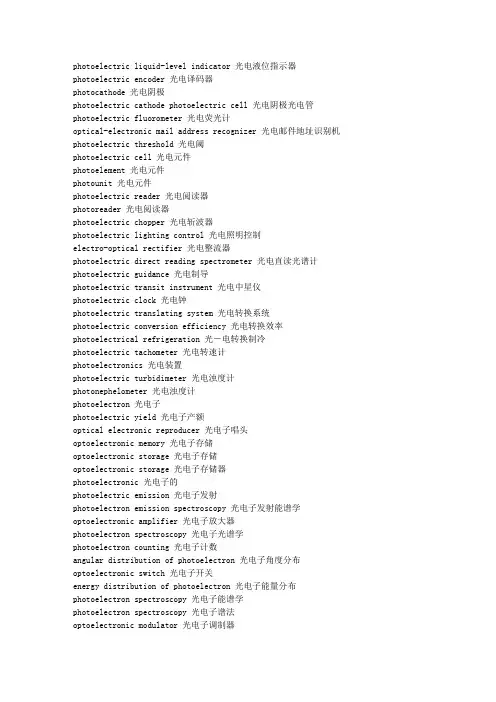
photoelectric liquid-level indicator 光电液位指示器photoelectric encoder 光电译码器photocathode 光电阴极photoelectric cathode photoelectric cell 光电阴极光电管photoelectric fluorometer 光电荧光计optical-electronic mail address recognizer 光电邮件地址识别机photoelectric threshold 光电阈photoelectric cell 光电元件photoelement 光电元件photounit 光电元件photoelectric reader 光电阅读器photoreader 光电阅读器photoelectric chopper 光电斩波器photoelectric lighting control 光电照明控制electro-optical rectifier 光电整流器photoelectric direct reading spectrometer 光电直读光谱计photoelectric guidance 光电制导photoelectric transit instrument 光电中星仪photoelectric clock 光电钟photoelectric translating system 光电转换系统photoelectric conversion efficiency 光电转换效率photoelectrical refrigeration 光-电转换制冷photoelectric tachometer 光电转速计photoelectronics 光电装置photoelectric turbidimeter 光电浊度计photonephelometer 光电浊度计photoelectron 光电子photoelectric yield 光电子产额optical electronic reproducer 光电子唱头optoelectronic memory 光电子存储optoelectronic storage 光电子存储optoelectronic storage 光电子存储器photoelectronic 光电子的photoelectric emission 光电子发射photoelectron emission spectroscopy 光电子发射能谱学optoelectronic amplifier 光电子放大器photoelectron spectroscopy 光电子光谱学photoelectron counting 光电子计数angular distribution of photoelectron 光电子角度分布optoelectronic switch 光电子开关energy distribution of photoelectron 光电子能量分布photoelectron spectroscopy 光电子能谱学photoelectron spectroscopy 光电子谱法optoelectronic modulator 光电子调制器photoelectron statistics 光电子统计学photoelectron image 光电子图像photoelectronic phenomena 光电子现象optical electronics 光电子学optoelectronics 光电子学photoelectronics 光电子学optoelectronic 光电子学的optoelectronic shutter 光电子学光闸electrooptical character recognition 光电字符识别 l ight resistance 光电阻optical superposing 光叠加photodynamic inactivation 光动力钝化作用photodynamic substance 光动力物质photodynamics 光动力学photodynamic action 光动力作用 photokinesis 光动态photokinesis 光动性photodinesis 光动状态photosensing marker 光读出标记luminosity 光度photometric scale 光度标photometric standard 光度标准photometric parameter 光度参数photometric measurement 光度测量photometry 光度测量method of photometric interpolation 光度插入法photometric unit 光度单位photometric titration 光度滴定photometric titration 光度滴定法photometry 光度法light-distribution photometer 光度分布计photometric pyrometer 光度高温计photometric orbit 光度轨道 - 食双星luminosity function 光度函数photometric integrator 光度积分器photometric integrating sphere 光度积分球photometric primary standard 光度基准器luminosity class 光度级optimeter 光度计photometer 光度计photometric computer 光度计算机photometric calibration 光度校准photometric distance 光度距离photometric aperture 光度孔径photometric paradox 光度矛盾luminosity curve 光度曲线photometric parallax 光度视差photometric binary 光度双星 - 即食双星photometric bench 光度台overluminous star 光度特大恒星photometric system 光度系统luminosity rate 光度效率luminosity class 光度型photometry 光度学luminosity evolution 光度演化luminosity paradox 光度佯谬photometric paradox 光度佯谬telephotometry 光度遥测法telephotometry 光度遥测术photometric diameter 光度直径photodimerization 光二聚photodimerization 光二聚作用luminous emittance 光发射度light emitting diode 光发射二极管photoemissivity 光发射能力optical emission spectrography 光发射摄谱学photocell 光发射元件optical transmitter 光发送机light valve 光阀 photovalve 光阀light valve display 光阀显示light valve array 光阀阵列photon sail 光帆light reflex 光反射luminous reflectance 光反射比light reaction 光反应photoreaction 光反应photoreactive chlorophyll 光反应性叶绿素light amplifier 光放大器optical amplifier 光放大器photolysis 光分解photovoltaic device 光伏器件photovoltaic sensor 光伏式传感器photovoltaic transducer 光伏式传感器photovoltaic detector 光伏探测器photovoltaic effect 光伏效应solar photovoltaic energy system 光伏型太阳能源系统optical character recognition 光符号识别optical character recognition 光符识别optical character recognition application 光学字符识别应用optical character recognition device 光符识别装置light radiation 光辐射optical radiation 光辐射optical radiation standard 光辐射标准器photoreactivation 光复活photoreactivating enzyme 光复活酶photoreactivating deficient mutant 光复活缺陷突变型photoreactivation repair 光复活修复photoreactivation 光复活作用optical interferometry 光干涉量度学polished rod 光杆stroke of polished rod 光杆冲程polished rod horsepower 光杆功率position of polished rod 光杆位置light sensation 光感sensillum opticum 光感器photoreception 光感受photoreceptor 光感受器photoreception 光感受作用optical lever 光杠杆opto-isolator 光隔离器photoisolator 光隔离器optical tracking satellite 光跟踪卫星optical tracker system 光跟踪系统optical tracking system 光跟踪系统mechanical equivalent of light 光功当量optical soliton 光孤子photo-curing 光固化light-cured composite 光固化复合树脂photocurable polyimide 光固化聚酰亚胺light-cured resin 光固化树脂photocureable coating 光固化涂料light curring unit 光固化装置X-ray tube X光管 bare pipe 光管light pipe 光管light-pipe optics 光管光学optical track 光盘轨optical track pitch 光轨间距light-compass reaction 光晷反应smooth roll 光辊photosensitivity 光过敏photosensitization 光过敏bare electrode 光焊条photosynthetic ratio 光合比photosynthetic number 光合比值photosynthate 光合产物photosynthetic product 光合产物photosynthetic unit 光合单位photosynthetic 光合的photosynthetic electron transport 光合电子传递photosynthetic activity 光合活性photophosphorylation 光合磷酸化photophosphorylase 光合磷酸化酶optical combiner 光合路器photosynthetic intensity 光合强度photosynthetic pigment 光合色素photosynthetic quotient 光合商photosynthetic carbon metabolism 光合碳代谢Calvin cycle 光合碳还原环photosynthetic carbon reduction cycle 光合碳还原环photosystem 光合体系 photosynthetic bacteria 光合细菌photosynthetic efficiency 光合效率photoheterotroph 光合异养生物photosynthetic active radiation 光合有效辐射photosynthetically active radiation 光合有效辐射photoautotrophic 光合自养的photosynthetic tissue 光合组织photosynthesis 光合作用epipelagic 光合作用带的photosynthesis science 光合作用科学photosynthesis physiology 光合作用生理学photosynthetic bacteria 光合作用细菌photonuclear reaction 光核反应Prunus mira Koehne. 光核桃smooth pit peach 光核桃photonucleon 光核子optically thick medium 光厚介质 - 光深τ>1的介质photorespiration 光呼吸photorespiration 光呼吸作用smooth approximation 光滑逼近smooth boundary 光滑边界glare ice 光滑冰smooth invariant measure 光滑不变测度smooth measure 光滑测度smooth hypersurface 光滑超曲面slickens 光滑冲积层glassy 光滑的glossy 光滑的laevigate 光滑的laevigatus 光滑的laevis 光滑的levigate 光滑的sleek 光滑的smooth point 光滑点smooth two-dimensional manifold 光滑二维流形smoothing equation 光滑方程smooth function 光滑函数smoothing function 光滑函数smooth kernel 光滑核smoothing problem 光滑化问题slick joint 光滑接头smooth structure 光滑结构smoothing solution 光滑解smooth colony 光滑型菌落smooth manifold 光滑流形smooth plane curve 光滑平面曲线smooth surface 光滑曲面smooth curve 光滑曲线smoothing operator 光滑算子smooth broach 光滑髓针smooth core rotor 光滑铁心转子smooth type 光滑型smooth sequence 光滑序列smooth map 光滑映射smooth mapping 光滑映射actinic glass 光化玻璃Einstein's law of photochemical equivalence 光化当量的爱因斯坦定律actinic 光化的actinoelectricity 光化电photoionization 光化电离actinicity 光化度actinism 光化度photochemical reaction 光化反应actinic radiation 光化辐射actinic focus 光化焦点actinic green 光化绿actinic green glass 光化绿玻璃actinic rays 光化射线actinicity 光化性actinic chemistry 光化学actinochemistry 光化学actinology 光化学photochemistry 光化学chemosphere 光化学层photochemical rearrangement 光化学重排first law of photochemistry 光化学第一定律photochemical cell 光化学电池photochemical kinetics 光化学动力学photochemical reaction 光化学反应reaction kinetics of photochemistry 光化学反应动力学photochemical process 光化学过程photochemically reactive hydrocarbons 光化学活性碳氢化合物photochemical processing 光化学加工photochemical crosslinking 光化学交联photochemotherapy 光化学疗法photochemical equilibrium 光化学平衡photo chemical vapor deposition 光化学气相沉积Photo-CVD 光化学气相沉积photochemical stability 光化学稳定性photochemical pollutant 光化学污染物photochemical fog 光化学雾photochemical smog 光化学烟雾photochemical smog kinetics 光化学烟雾动力学photochemical oxidant 光化学氧化剂photochemical transformation 光化学转化photochemical smog 光化烟雾photochemical induction 光化学诱导actinism 光化作用photoreduction 光还原ring of light 光环sight reticle camera 光环摄影机halo effect 光环效应photopsy 光幻觉lumiflavin 光黄素light fog 光灰雾mithramycin 光辉霉素photoactivation 光活化photoactive reaction 光活化反应optical active matter 光活性剂optical active polymer 光活性聚合物X-ray machine X光机opto-mechanical scanner 光机扫描器optical-mechanical scanner 光机扫描仪optical-mechanical system 光机系统light distortion 光畸变photothyristor 光激半导体闸流管photostimulated ionization 光激电离optically active material 光激活材料light-activated switch 光激开关light-activated silicon controlled switch 光激可控硅开关light-activated silicon controlled rectifier 光激可控硅整流器photo-SCR 光激可控硅整流器photoexcitation 光激励phototonus 光激性photoluminescence 光激荧光现象photokinesis 光激运动post-maximum spectrum 光极大后光谱optical integrated circuit 光集成电路optical computer 光计算机optical recording 光记录optical recording media 光记录媒体optical relay 光继电器Aglaspida 光甲目Anoplophora glabripennis 光肩星天牛optical detector 光检测器photodetector 光检测器light degradation 光降解photodegradation 光降解photodegradable polymer 光降解聚合物light step 光阶optical receiver 光接收器bareface fabric 光洁不起绒织物bright quenching 光洁淬火clean hardening 光洁淬火finish 光洁度smooth finish 光洁度smoothness 光洁度roughness meter 光洁度计clean thread 光洁螺纹clean-cut timber 光洁木材photodecomposition 光解photolysis 光解作用protolysis 光解反应叶绿素photodissociation 光解离photolytic silver 光解银photomeson 光介子photopion nuclear physics 光π介子核物理学optotransistor 光晶体管optical path 光径radius-luminosity relation 光径关系light microscope 光镜optical moment 光矩optical system 光具组optical bench 光具座bench photometer 光具座式光度计photo polymerization 光致聚合photopolymer 光聚合物photopolymerization 光聚作用optical switch 光开关photoengraving 光刻photoetching 光刻photolithography 光刻photoetching material 光刻材料photoetching 光刻法photolithographic process 光刻工艺photolithography technique 光刻工艺mask aligner 光刻机photolithography limitation 光刻极限photoetch integrated circuit 光刻集成电路photoetching technique 光刻技术photoresist 光刻胶photolithographic diffusion window 光刻扩散窗口photoetch pattern 光刻图案photolithographic mask layer 光刻掩蔽层photolithographic masking operation 光刻掩蔽工序phototched mask 光刻掩摸 light writer 光刻字机aperture color 光孔色 photophobia 光恐怖Raysistor 光控变阻器photoelectroluminescence 光控电致发光optically controlled gyro compass 光控回转罗盘photorelay 光控继电器photo-thyristor 光控晶闸管light-operated switch 光控开关photoswitch 光控开关photoimpact 光控脉冲light-dependent control element 光控元件optical control 光控制diaphragm 光阑diaphragm setting 光阑定位diaphragm aperture 光阑孔径diaphragm servomotor 光阑驱动伺服电动机diaphragm lens 光阑透镜optical cable 光缆optical fiber cable 光缆optical fibre cable 光缆optical cable distribution system 光缆分配系统optical cable splice 光缆接头optical cable connector 光缆连接器optical cable connector adapter 光缆连接器转接座optical cable driver 光缆驱动器optical cable communication 光缆通信optical cable assembly 光缆组件light aging 光老化lidar 激光雷达optical radar 光雷达photoionization 光离子化photoionization detector 光离子化检测器photomechanics 光测力学optomechanics 光力学granulation 光粒组织optical connector 光连接器optical link 光链路glitter 光亮clean annealing 光亮退火bright quenching oil 光亮淬火油nitid 光亮的nitidum 光亮的bright plating 光亮电镀bright current density range 光亮电流密度范围luminance 光亮度luminance brightness 光亮度bright plating 光亮镀gilding brass 光亮黄铜brightener 光亮剂brightening agent 光亮剂bright pickling 光亮浸蚀bright drawing 光亮拉丝bright coal 光亮煤bright heat treatment 光亮热处理bright heat treatment wire 光亮热处理钢丝bright adaptation 光亮适应luminous quantities 光亮数量bright annealing 光亮退火light annealing 光亮退火bright annealing furnace 光亮退火炉bright stock 光亮油料Lampridiformes 光亮鱼目magnitude of light 光量quantity of light 光量actinography 光量测定法photometry 光量法light control 光量控制light control tape 光量控制带light control characteristic 光量控制特性light quantum 光量子photon 光量子optical quantum counter tube 光量子计数管quantum theory of light 光量子论phototherapy 光疗light therapy 光疗法photophosphorylation 光合磷酸化作用optical homodyne detection 光零差探测light stream 光流photohalogenation 光卤化carnallite 光卤石photographic recording 光录声optical path 光路optical path length 光路长度reversibility of optical path 光路可逆性optical filter 光滤波器smooth millboard 光面纸板smooth-surfaced roofing 光面屋面halo blight 光轮疫病halonate 光轮状light-compass orientation 光罗盘定向blank bolt 光螺栓pulsed light 光脉冲optical pulse generator 光脉冲发生器amplification of light pulse 光脉冲放大photo-impulses counting 光脉冲计数optical pulse counter 光脉冲计数器optical pulse counting 光脉冲记数compression of light pulse 光脉冲压缩compression technique of light pulse 光脉冲压缩技术photogermination 光萌发optical density 光密度light densitometer 光密度计optically denser medium 光密介质streamer 光幂 grain side 光面bright steel wire 光面钢丝refacer 光面机plain arch 光面拱skidding tire 光面轮胎smooth tread tyre 光面轮胎smooth endoplasmic reticulum 光面内质网smooth surfaced endoplasmic reticulum 光面内质网Leiotriletes 光面三缝孢属glossy paper 光面相纸glossy print 光面照片glassy millboard 光面纸板plane ashlar 光面琢石light sensing 光敏photovaristor 光敏变阻器photosensitive glass 光敏玻璃phototropic glass fiber 光敏玻璃纤维photoconductive film 光敏薄膜photosensitizer 光敏材料light sensitive layer 光敏层photodarlington 光敏达林顿放大器light sensitive 光敏的photosensitive 光敏的light sensitive cell 光敏电池photo-potentiometer 光敏电位器photovaristor 光敏电阻photoresistor 光敏电阻light sensitive resistance ceramics 光敏电阻瓷photoresistor ceramics 光敏电阻瓷light sensitive resistor 光敏电阻器ligt resistor 光敏电阻器photo-resistor 光敏电阻器light sensitive diode 光敏二极管photosensitive diode 光敏二极管optical sensor 光敏感器photo-sensor 光敏感器photosensitivity 光敏感性light sensor 光敏感元件photosensor 光敏感元件photosensitivity disorder 光敏感障碍light sensitive seed 光敏感种子light-sensitive tube 光敏管photosensitive tube 光敏管photosensitization 光敏化photosensitizer 光敏剂light sensitive relay 光敏继电器photosensitive relay 光敏继电器photosensitive detector 光敏检波器photosensitive adhesive 光敏胶粘剂actinodielectric 光敏介电的optical transistor 光敏晶体管phototransistor 光敏晶体管phototransistor circuit 光敏晶体管电路phototransistor matrix 光敏晶体管阵列phototransistor 光敏晶体三极管photopolymer 光敏聚合物photosensitive polymer 光敏聚合物light activated switch 光敏开关light-activated silicon switch 光敏可控硅整流器photosensing device 光敏器件photosensor 光敏器件phototransistor 光敏三极管phototriode 光敏三极管phytochrome 光敏色素light-sensitive detector 光敏探测器photaceram 光敏微晶玻璃photosensitive glass-ceramics 光敏微晶玻璃photo document sensor 光敏文件感受器photoinitiator 光敏引发剂light-sensitive cell 光敏元件photosensitive element 光敏元件photosensor 光敏元件photo-thyristor 光敏闸流管photosensitization 光敏作用Guangming 光明lucensomycin 光明霉素optical mode 光模optical analog memory 光模拟存储器optical pattern recognition 光模式识别luminous energy 光能actionoscope 光能测定器actinometry 光能测定学actinometer 光能测定仪photosynthesis 光能合成photoenergetics 光能力学phototroph 光能利用菌efficiency for solar energy utilization 光能利用率phototrophic bacteria 光能利用细菌actinometry 光能强度测定actinogram 光能曲线图photolithotrophy 光能无机营养photolithotrophic bacteria 光能无机营养菌photoheterotrophic bacteria 光能异养菌photoheterotroph 光能异养生物photoorganotrophy 光能有机营养photoorganotrophic bacteria 光能有机营养菌photoautotrophy 光能自养photoautotrophic bacteria 光能自养菌photo-autotroph 光能自养生物light year 光年lyear 光年photo viscoelasticity 光粘弹性photocoagulator 光凝固器photocoagulator 光凝结器light button 光钮optical coupling 光耦合light-coupled semiconductor switch 光耦合半导体开关optically coupled isolator 光耦合隔离器optical coupler 光耦合器optocoupler 光耦合器photocoupler 光耦合器light beating spectroscopy 光拍光谱学optical disc 光盘optical disk 光盘optical disc drive 光盘驱动器optical disc servo control system 光盘伺服控制系统wedge 光劈optical biasing 光偏置light deflection 光偏转optical deflector 光偏转器optodeflector 光偏转器photobleaching 光漂白clean bill 光票clean payment credit 光票付款信用证clean payment letter of credit 光票付款信用证clean remittance 光票汇款clean rate 光票利率clean collection 光票托收collection on clean bill 光票托收clean credit 光票信用证clean letter of credit 光票信用证optical frequency 光频optical frequency standard 光频标optical isolator 光频隔离器optical frequency division multiplexing 光频频分复用optical phonon 光频声子optical double magnetic resonance 光频双磁共振optical branch 光频支optical screen 光屏photomask agent 光屏蔽剂optical screen reader 光屏读数器light spectrum 光谱optical spectrum 光谱spectrum 光谱semiquantitative spectrometric analysis 光谱半定量分析spectral background 光谱背景spectrocomparator 光谱比较仪spectrum variable 光谱变星spectral standard solar cell 光谱标准太阳电池spectrometry 光谱测定法spectral measurement 光谱测量spectrophone 光谱测声器spectral component 光谱成分spectral pure 光谱纯spectroscopically pure 光谱纯spectroscopically pure graphite 光谱纯石墨spectral bandwidth 光谱带宽spectral 光谱的spectroscopic lamp 光谱灯spectroelectrochemistry 光谱电化学quantitative spectrochemical analysis 光谱定量分析quantitative spectrometric analysis 光谱定量分析qualitative spectrometric analysis 光谱定性分析spectral luminous efficiency 光谱发光效率spectral emissivity 光谱发射率spectral reflectance 光谱反射spectral reflectance 光谱反射比spectral range 光谱范围spectral directional reflectance factor 光谱方向反射因子spectrum emission 光谱放射率spectral resolution 光谱分辨率spectral distribution 光谱分布spectral distribution curve 光谱分布曲线spectral distribution graph 光谱分布图spectrum order sorter 光谱分级器spectral classification 光谱分类spectral analysis 光谱分析spectrographic analysis 光谱分析spectrum analysis 光谱分析spectrum analyser 光谱分析器physics of spectroscopic analysis 光谱分析物理学error in spectrochemical analysis 光谱分析误差spectral peak 光谱峰bandwidth of emission spectrum 光谱辐射带宽spectral radiometry 光谱辐射度量学spectrum radiator 光谱辐射计spectral radiance factor 光谱辐射亮度因子spectral radiance 光谱辐射率spectral radiant energy 光谱辐射能spectral radiance energy 光谱辐射能量spectral radiant flux 光谱辐射通量spectral radiant gain 光谱辐射增益spectral radiant illuminance standard lamp 光谱辐射照度标准灯spectral irradiance 光谱辐照度spectral irradiance distribution 光谱辐照度分布spectral interference 光谱干扰spectral photographic plate 光谱感光板spectral sensitivity 光谱感光度spectral pyrometer 光谱高温计spectrophotometric colorimetry 光谱光度测色法spectral-luminosity classification 光谱-光度分类法spectrum-luminosity diagram 光谱光度图 - 即赫罗图spectral photometry 光谱光度学spectral luminous efficiency 光谱光视效率spectral luminous efficiency curve 光谱光视效率曲线spectral luminous efficacy 光谱光视效能spectroscopic optics 光谱光学spectral locus 光谱轨迹spectrum locus 光谱轨迹spectrochemistry 光谱化学qualitative spectrochemical analysis 光谱化学定性分析spectrochemical analysis 光谱化学分析spectrochemical series 光谱化学系列spectral buffer 光谱缓冲剂spectroscopic buffer 光谱缓冲剂excitation of spectra 光谱激发order of spectrum 光谱级spectrograde 光谱级spectroscopic technology 光谱技术spectrum technology 光谱技术spectral discrimination 光谱鉴别spectral discriminator 光谱鉴别器spectral mirror 光谱镜spectral width 光谱宽度spectroscopic prism 光谱棱镜quantum theory of spectra 光谱量子理论spectral sensitivity 光谱灵敏度spectrum sensitivity 光谱灵敏度spectral sensitivity characteristic 光谱灵敏度特性曲线spectral filtering 光谱滤波spectral density 光谱密度spectrum-density diagram 光谱-密度图spectral sensitivity 光谱敏感性spectral energy distribution 光谱能量分布spectral power distribution 光谱能量分布spectral mach 光谱配色spectrum matching 光谱匹配spectro-polarimeter 光谱偏光计spectral shift 光谱偏移spectral intensity 光谱强度spectral region 光谱区spectral tristimulus values 光谱三色刺激值spectral tristimulus values 光谱三色激励值spectral color 光谱色spectrum color 光谱色spectrocolorimeter 光谱色度计spectrocolorimetry 光谱色度学spectral chromaticity coordinates 光谱色度坐标spectroscopic entropy 光谱熵spectral photography 光谱摄影学spectrophotography 光谱摄影学spectral discrimination 光谱识别spectrographic laboratory 光谱实验室spectroscopic test 光谱试验spectral character 光谱特性spectral characteristic 光谱特性spectral property 光谱特性spectrum projector 光谱投影仪spectrum transparency region 光谱透明区spectral transmittance 光谱透射比spectrogram 光谱图spectrum chart 光谱图spectroscopic displacement law 光谱位移律spectral line 光谱线 spectrum line 光谱线spectral linewidth 光谱线宽度broadening of spectral line 光谱线增宽spectral responsivity 光谱响应度spectral response range 光谱响应范围spectral response curve 光谱响应曲线spectral response characteristic 光谱响应特性曲线spectral term 光谱项spectroscopic term 光谱项spectral extinction 光谱消色spectral information 光谱信息spectral type 光谱型spectral sequence 光谱序spectrography 光谱学spectroscopy 光谱学spectroscopist 光谱学家optical spectrometer 光谱仪spectrograph 光谱仪spectrometer 光谱仪spectrophotometer 光谱仪spectrofluorometer 光谱荧光计spectroscopic carrier 光谱载体spectral sensitization 光谱增感spectral index 光谱指数day neutral 光期钝感day-neutral plant 光期钝感植物lac varnish 光漆phosgene 光气photon drag detector 光牵探测器light preamplifier 光前置放大器light gun 光枪mode of optical cavity 光腔振荡模式intensity of light 光强light intensity 光强light intensity 光强度luminous intensity 光强度optical power 光强度luminous intensity measurement 光强度测量enhancement of light intensity differences 光强度差增强luminous intensity sensitivity 光强灵敏度intensity modulation 光强调制photoaffinity labeling 光亲和标记photosphere 光球photospheric eruption 光球爆发photospheric facula 光球层光斑。
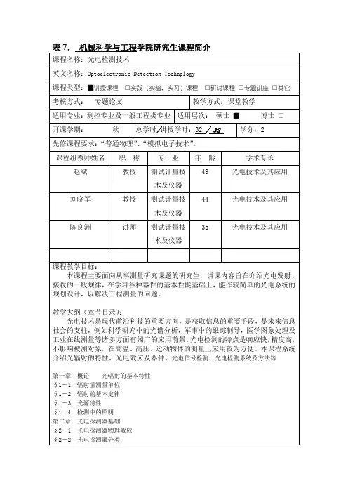
《光电检测技术》教学大纲课程代码:课程中文名:光电检测技术课程英文名:课程类别:专业技术科适用专业:光伏材料应用、光伏发电应用、电子技术等专业课程学时: 48学时课程学分: 3学分一、课程的专业性质、地位和作用(目的)1、性质:必修2、地位:光电检测技术是光学与电子学技术相结合而产生的一门新型检测技术,它是利用电子技术对光学信息进行检测,并进一步传递、存储、控制、计算和显示。
光电检测技术是现代检测技术最重要的手段和方法之一。
3、作用:通过本课程的教学,使学生了解和掌握各种光电器件的结构、工作原理、工作过程、工作特性及其基本的应用,培养学生通过了解器件的性能特点来搭建检测系统的能力,培养学生学习的能力和综合运用知识的能力,培养学生理论联系实际的学风和科学态度,提高学生的分析处理实际问题的能力,为以后的工作和学习打下基础。
二、教学内容、学时分配和教学的基本要求第一章光电检测应用中的基础知识6学时,其中理论教学 6 学时,实践或其他教学0 学时1.1 辐射度学和光度学基本概念1.2 半导体基础知识1.3 基本概念1.4 光电探测器的噪声和特性参数重点:辐射度学和光度学基本概念难点:光电探测器的噪声和特性参数教学要求:本章介绍了光电检测应用中的基础知识,要求学生对基本概念有理解,进而掌握光电探测器的噪声及特性参数第二章光电检测中的常用光源3学时,其中理论教学3学时,实践或其他教学0学时2.1 光源的特性参数2.2 热辐射源2.3 气体放电光源2.4 固体发光光源2.5 激光器重点:光源的特性参数难点:气体、固体发光光源和激光器的工作原理教学要求:本章要求学生掌握各种固体发光的工作原理及其应用第三章结型光电器件 6 学时,理论教学6 学时,实践或其他教学0学时3.1 结型光电器件工作原理3.2 硅光电池3.3 硅光电二极管和硅光电三极管3.4 结型光电器件的放大电路3.5 特殊结型光电二极管3.6 结型光电器件的应用举例——光电耦合器件重点:结型光电器件的工作原理;硅光电池的工作原理及特性;硅光电二极管和硅光电三极管的性能比较难点:结型光电器件的放大电路及应用举例——光电耦合器件教学要求:要求学生掌握硅光电池的工作原理;硅光电二极管和硅光电三极管的性能比较及结型光电器件的放大电路及应用——光电耦合器件第四章光电导器件6学时,其中理论教学 6 学时,实践或其他教学0学时4.1光敏电阻的工作原理4.2 光敏电阻的主要性能参数4.3 光敏电阻的偏置电路和噪声4.4 光敏电阻的特点和应用重点:光敏电阻的工作原理和特性参数难点:光敏电阻的应用教学要求:要求学生掌握光敏电阻的工作原理及性能参数及光敏电阻的应用第五章真空光电器件3学时,其中理论教学3学时,实践或其他教学0学时5.1 光电阴极5.2 光电管与光电倍增管5.3 光电倍增管的主要特性参数5.4 光电倍增管的供电和信号输出电路5.5 微通道板光电倍增管5.6 光电倍增管的应用重点:光电管与光电倍增管的工作原理、特性参数难点:光电倍增管的供电和信号输出电路及应用教学要求:要求学生掌握光电管与光电倍增管的工作原理、特性参数及实际应用第六章真空成像器件3学时,其中理论教学3学时,实践或其他教学0学时6.1像管6.2常见像管6.3摄像管6.4光导靶和存储靶6.5摄像管的特性参数6.6摄像管的发展方向重点:像管与摄像管的工作原理难点:光导靶和存储靶的原理及摄像管的特性参数教学要求:要求学生掌握像管与摄像管的工作原理及特性参数第七章固体成像器6学时,其中理论教学 6 学时,实践或其他教学0学时7.1 电荷耦合器件7.2 电荷耦合器件的分类7.3 CCD摄像机分类7.4 CCD的特性参数7.5 自扫描光电二极管阵列7.6 固体摄像器件的发展现状和应用重点:电荷耦合器件的工作原理;CCD的特性参数难点:自扫描光电二极管阵列教学要求:要求学生掌握CCD固体成像器件的工作原理第八章红外辐射与红外探测器6学时其中理论教学 6 学时,实践或其他教学0学时8.1 红外辐射的基础知识8.2 红外探测器8.3 红外探测器的性能参数及使用中应注意的事项8.4 红外测温8.5 红外成像8.6 红外无损检测8.7 红外探测技术在军事上的应用重点:红外探测器的工作原理、性能参数及使用中应注意的事项难点:红外探测器的具体应用教学要求:要求学生掌握红外辐射的基础知识,并掌握红外探测器的各种具体应用第九章光导纤维与光纤传感器6学时其中理论教学 6 学时,实践或其他教学0学时9.1 光导纤维基础知识9.2 光导纤维的应用9.3 光纤传感器的分类及构成9.4 功能型光纤传感器9.5 非功能型光纤传感器重点:光导纤维的基础知识及功能型光纤传感器的工作原理难点:非功能型光纤传感器的工作原理教学要求:要求学生掌握光导纤维的基础知识,并掌握光纤传感器的工作原理第十章太赫兹波的产生与检测3学时其中理论教学 3 学时,实践或其他教学0学时10.1 概述10.2 THz辐射光谱学10.3 THz辐射成像重点:THz辐射成像的原理难点:THz辐射成像的原理教学要求:要求学生掌握THz辐射成像的原理三、各章节教学课时分配表本课程各部分教学内容计划学时数分配如下:四、课程的考核办法和成绩评定:1、考试 2.笔试(闭卷)3.平时成绩比重:平时成绩(包括考勤、作业、答疑、课堂练习、课外实验、等)占30%4.期末成绩比重:卷面考试占70%。
目录《DSP原理及应用》课程中英文简介 (3)《毕业设计》课程中英文简介 (4)《测量仪器设计》课程中英文简介 (5)《传感技术及应用》课程中英文简介 (6)《磁测量》课程中英文简介 (7)《单片机功率接口技术》课程中英文简介 (8)《单片机原理及应用》课程中英文简介 (9)《单片机原理及应用课程设计》课程中英文简介 (10)《电气控制技术》课程中英文简介 (11)《电子测量原理》课程中英文简介 (12)《辐射测温学》课程中英文简介 (13)《高频电子线路》课程中英文简介 (14)《高速数字电路设计与应用》课程中英文简介 (15)《工程软件基础》课程中英文简介 (16)《光电检测技术》课程中英文简介 (17)《过程控制技术与系统》课程中英文简介 (18)《机器视觉及其应用》课程简介 (19)《精密测控电路与驱动技术》课程中英文简介 (20)《精密测量理论与技术》课程中英文简介 (22)《精密仪器设计》课程中英文简介 (23)《企业专家讲座》课程中英文简介 (24)《嵌入式系统设计》课程中英文简介 (25)《生产实习》课程中英文简介 (26)《数字逻辑与系统设计》课程简介 (28)《数字信号处理》(双语)课程中英文简介 (30)《微波技术基础》课程中英文简介 (32)《物理光学》课程中英文简介 (33)《误差理论与不确定度分析》课程中英文简介 (34)《信号与系统Ⅰ》课程中英文简介 (35)《信号与系统Ⅱ》课程中英文简介 (36)《虚拟仪器软件设计》课程中英文简介 (37)《仪器通用扩展接口及设计》课程中英文简介 (38)《应用光学》课程中英文简介 (39)《质量工程与可靠性设计》课程中英文简介 (41)《专业导论课》课程中英文简介 (42)《专业综合实践》课程中英文简介 (43)《自动测试系统》课程中英文简介 (44)《自动测试系统课程设计》课程中英文简介 (45)《自动检测技术》课程中英文简介 (46)《DSP原理及应用》课程中英文简介课程编码:SE01100200课程中文名称:DSP原理及应用课程英文名称:DSP Principle and Application总学时:32学分:2课程简介:本课程将对数字信号处理器(DSP)的特点、结构、基本原理和应用进行详细介绍。
激光、光电、光学词汇中英文对照1. 激光(Laser)2. 光电效应(Photoelectric Effect)3. 光学(Optics)4. 光纤(Fiber Optic)5. 光谱(Spectrum)6. 折射率(Refractive Index)7. 透镜(Lens)8. 反射(Reflection)9. 干涉(Interference)10. 衍射(Diffraction)11. 偏振(Polarization)12. 激光切割(Laser Cutting)13. 激光焊接(Laser Welding)14. 光电探测器(Photoelectric Detector)15. 光电传感器(Photoelectric Sensor)16. 光学显微镜(Optical Microscope)17. 光学望远镜(Optical Telescope)18. 光学镜头(Optical Lens)19. 光学滤波器(Optical Filter)20. 光学编码器(Optical Enr)21. 光学通信(Optical Communication)22. 光学存储(Optical Storage)24. 光学子系统(Optical Subsystem)25. 光学设计(Optical Design)26. 光学加工(Optical Fabrication)27. 光学镀膜(Optical Coating)28. 光学检测(Optical Inspection)29. 光学成像(Optical Imaging)30. 光学治疗(Optical Therapy)31. 光学材料(Optical Materials)32. 光学元件(Optical Elements)33. 光学路径(Optical Path)34. 光学平台(Optical Platform)35. 光学子件(Optical Component)36. 光学连接器(Optical Connector)37. 光学开关(Optical Switch)38. 光学调制器(Optical Modulator)39. 光学衰减器(Optical Attenuator)40. 光学放大器(Optical Amplifier)41. 光学显示器(Optical Display)42. 光学子午线(Optical Meridian)43. 光学分辨率(Optical Resolution)44. 光学畸变(Optical Distortion)45. 光学厚度(Optical Thickness)46. 光学密度(Optical Density)48. 光学干涉仪(Optical Interferometer)49. 光学相干断层扫描(Optical Coherence Tomography)50. 光学扫描器(Optical Scanner)51. 光学跟踪(Optical Tracking)52. 光学遥感(Optical Remote Sensing)53. 光学成像系统(Optical Imaging System)54. 光学跟踪系统(Optical Tracking System)55. 光学定位系统(Optical Positioning System)56. 光学子午仪(Optical Meridian Instrument)57. 光学补偿器(Optical Compensator)58. 光学补偿器(Optical Corrector)59. 光学基准(Optical Reference)60. 光学基准面(Optical Reference Plane)这些词汇涵盖了激光、光电和光学领域的基本概念、技术和设备。
课程编号:ME3321286 课稈名称:光电检测技术学分/学时:2/32+实验适用专业:测控技术与仪器专业《光电检测技术》教学大纲英文名称:Optic-electronic detection technology课稈性质:选修课,建议开设学期:6先修课程:大学物理、电路、传感器、电了测量、电了测量技术、传感器与信号调理开课单位:机电工稈学院测控与仪器系一、课程的教学目标与任务木课稈是测控专业学生的一门技术基础课。
光电技术是将传统的光学技术与现代微电了技术、计算机技术紧密结合在一起的一门高新技术,它已渗透到许多科学领域,并得到迅猛的发展。
光电技术是一门综合性的学科,是现代科学的重要组成部分。
由它产生的一门重要技术:光电检测技术是现代测量技术屮的一个重要组成部分。
特别是近年来,各种新型光电探测器件的出现,要求学测控专业的人才必须掌握这门课程。
二、课程具体内容及基本要求(一)光电信息技术(3学时)1.基木要求:了解信息与光电信息技术,光电信息技术与光电检测技术的关系,典型的光电测试系统,以及光电测试技术的发展及其特点。
强调:“重要的不是获取知识,而是发展思维能力”。
(二)光电检测技术基础(4学时)1.基本要求:掌握光度学的基本物理量和基木定律,光辐射在空气屮传播的基本概念; 了解和掌握光源的基木参数;了解光电系统中的常用光源:热辐射光源、气体放电光源、半导体发光器件及激光光源等的原理、特性及其对光电检测的影响。
2.重点和难点重点:光度学中各物理量的基木概念和基木定律。
难点:如何根据光电检测的实际要求,合理选用适当的光源。
(三)光电检测器件(6学时)1.基木要求:了解光电管;光电倍增管;光敏电阻;光敏二极管;光敏三极管;光电耦合器;光电池;位敏传感器;热释电;热电偶;光栅尺;光电编码器等光电传感器。
2.重点和难点重点光电探测器是光电探测系统的硬件支撑难点原理(四)光电探测系统的信噪比(4学时)1.基木要求:了解光电测试系统的精度与信噪比的关系,噪声的来源与分类,噪声的抑制。
机电工程学院课程简介2009年5月目录测试技术 (4)计算机控制技术(测控) (5)计算机控制技术(自动化) (6)精密检测技术 (7)PLC课程设计 (8)Protel电路设计 (10)VB编程 (10)变频器应用课程设计 (11)变频器应用课程设计 .......................................... 错误!未定义书签。
变频器应用课程设计 .......................................... 错误!未定义书签。
传感器认识实习 .. (12)单片机原理与应用 (13)光电检测技术 (17)计算机通信网络课程 (18)检测与传感器技术 (19)检测与转换技术 (19)控制仪表及装置(测控与仪器) (20)人机界面工程技术 (21)认识实习 (22)数字信号处理 (24)微机原理 (25)现代测控技术与系统 (26)现代测控与系统课程设计 (27)信号与系统 (28)虚拟仪器初步 (29)智能仪表课程设计 (30)系统辨识 (31)控制仪表及装置 (32)计算机控制技术 (32)计算机控制技术实验 (32)电子线路的计算机仿真 (32)模拟电子技术基础 (32)电路理论基础 (32)最优化方法 (32)电力电子技术 (32)电机与拖动 (40)自动控制原理实验 (41)自动控制原理 (42)数字信号处理 (43)数值分析 (44)数据库管理系统 (45)C/C++程序设计 (46)微机原理 (47)数控技术 (48)汽车工程基础 (49)机电一体化系统设计课程设计 (50)机电一体化系统设计 (51)工程流体力学 (52)计算机辅助设计与制造(CAD/CAM应用软件) (53)机械制造技术基础 (54)机械制图课程设计 (55)画法几何与机械制图 (56)液压与气压传动 (57)特种加工 (58)机电系统计算机控制 (59)互换性与测量技术基础 (60)电器与可编程控制器应用技术 (61)先进制造技术 (62)数控机床系统设计课程设计 (63)数控机床系统设计 (64)理论力学 (65)工业机器人学 (66)材料力学 (67)计算机绘图 (68)电工学(1) (69)电工学(2) (70)电工实验(1) (71)电工实验(2) (72)机电传动控制 (73)机械设计 (74)机械设计课程设计 (75)机械原理 (76)机械原理课程设计 (77)工程材料及成型技术 (78)金工实习 (79)数控技术 (80)控制仪表及装置(自动化) (81)模拟电子技术基础 (82)机电传动控制 (83)现代控制理论基础 (84)控制技术仿真及计算机辅助设计 (85)生产实习 (86)模具技术基础 (87)成功大学生活 (88)测试技术课程代码:80018000课程名称:测试技术英文名称:Measure Technology学分:3.5 开课学期:第7学期授课对象:机械设计制造及其自动化专业先修课程:自动控制原理,理论力学课程简介:《测试技术》是机械设计制造及其自动化专业的一门重要的专业选修课程。
光电英语专业词汇English:"Photonics, as a field of study and industry, encompasses a wide range of specialized terminology essential for understanding its principles, applications, and technologies. Some fundamental terms include 'photon,' which refers to a particle representing a quantum of light and electromagnetic radiation; 'optics,' the branch of physics that deals with the behavior and properties of light; 'semiconductor,' a material with electrical conductivity between that of a conductor and an insulator, crucial for photonics applications such as LEDs and lasers; 'laser,' an acronym for Light Amplification by Stimulated Emission of Radiation, a device that emits coherent light through an optical amplification process; 'fiber optics,' the transmission of light through thin, transparent fibers of glass or plastic, widely used in telecommunications for high-speed data transmission;'photovoltaics,' the conversion of light into electricity using semiconductors, crucial for solar energy applications;'photodetector,' a device that converts light into electrical signals, essential for sensing and detection applications in photonics;'optoelectronics,' the study and application of electronic devices thatsource, detect, and control light, pivotal for modern communication and sensing technologies; 'photonic crystal,' a periodic optical nanostructure that controls the flow of light, enabling various optical functionalities and devices; and 'quantum optics,' the branch of optics that studies the quantum properties of light and its interaction with matter, with profound implications for quantum computing and communication."中文翻译:"光电学作为一门研究领域和产业,涵盖了广泛的专业术语,对于理解其原理、应用和技术至关重要。
光电离检测法
光电离检测法(Photoionization Detection, PID)是一种用于气相色谱(Gas Chromatography, GC)的检测技术,它利用光子能量将样品分子中的电子激发到足够高的能级,从而实现电离。
这种技术主要用于检测具有易电离特性的化合物,如芳香族化合物、多环芳烃(PAHs)和一些卤代烃等。
光电离检测法的基本原理是,样品分子在通过带有紫外光(UV)或可见光的检测器时,光子的能量被分子吸收,导致分子中的电子跃迁到更高的能级。
如果光子的能量足够高,电子可以脱离分子,使分子带正电荷,从而实现电离。
这些带电的分子(离子)随后被检测器中的电极捕获,产生电流信号,这个信号可以被用来定量分析样品中的化合物。
光电离检测法的优点包括:
高灵敏度:对于某些化合物,尤其是具有易电离特性的化合物,PID可以提供非常高的检测灵敏度。
选择性:PID对特定类型的化合物具有较好的选择性,因为它依赖于分子的电离特性。
简单性:PID检测器结构相对简单,操作和维护也较为容易。
然而,PID也有其局限性,例如对于不易电离的化合物,
如饱和烃类,PID的灵敏度可能较低。
此外,PID检测器对于光子和电子的传输效率有一定要求,因此在使用时需要考虑样品的物理和化学特性。
光电离检测法在环境分析、食品安全、法医学、石油化工等领域有着广泛的应用,尤其是在检测痕量和超痕量有机污染物方面表现出色。
测控技术与仪器Measuring&ControlTechnologyandInstrumentations一、统编序号:1301二、专业代码:080401三、学位、学制:工学学士学位,学制为4年四、专业简介东北大学测控技术与仪器专业的前身是自动化仪表专业,始建于20世纪60年代,主要从事自动化领域的过程检测、过程控制与仪器仪表开发研究工作。
本专业隶属于国家重点一级学科“控制科学与工程”,具有“检测技术与自动化装置”的硕士、博士学位授予权,同时还具有测试计量技术及仪器的硕士学位授予权。
该专业教学力量雄厚,实验设备先进,为国家培养了大批优秀人才。
测控技术与仪器是信息技术的一个重要组成部分,是研究信息获取、信息处理、信息传输和利用的学科,是现代检测技术、电子技术、计算机技术、自动化技术、图像处理技术、光学工程和机械工程等学科互相交叉和融合的综合学科。
测控技术与仪器作为信息工业的源头是信息流中的重要一环,它伴随着信息技术的发展而发展,同时又为信息技术的发展发挥着不可替代的作用,成为涵盖“农轻重、海陆空、吃穿用”各领域内的国民经济的“倍增器”,科学研究的“先行官”,军事上的“战斗力”以及法制法规中的“物化法官”。
五、培养目标及专业范围本专业主要培养与信息检测和控制工程领域有关的信息处理、过程检测、过程控制、智能仪器及传感技术、机电一体化等方面的研究、开发、设计和制造,具有宽口径知识、较强适应能力和科学创新意识的高级人才。
六、毕业生应获得知识和能力(1)毕业生应掌握较扎实的数学、物理基础,具有较强的外语能力;(2)掌握必要的人文科学方面的知识;系统地掌握本专业领域较宽的基础理论知识,主要包括电路理论、电子技术,测量与控制,计算机应用技术,网络技术,信号处理,市场经济及企业管理等基础知识,了解本学科的前沿及发展趋势;(3)获得良好的工程实践训练,具有较强的计算机应用能力,掌握光、机、电、计算机相结合的当代检测与控制技术和实验研究技能,具有本专业测控技术、仪器仪表与系统的设计、开发及组织管理能力,获取新知识的能力与创新能力。
目录《毕业设计》课程中英文简介 (3)《单片机原理及应用》课程中英文简介 (4)《单片机原理及应用课程设计》课程中英文简介 (5)《辐射测温学》课程中英文简介 (6)《光电测试技术》课程中英文简介 (7)《光电仪器设计》课程中英文简介 (8)《光机电一体化设计与设备》课程中英文简介 (9)《光谱技术与仪器》课程中英文简介 (10)《光纤通讯技术》课程中英文简介 (11)《光学加工与检测技术》课程中英文简介 (12)《光学系统设计》课程中英文简介 (13)《红外与微光技术》课程中英文简介 (14)《激光原理与技术》课程中英文简介 (15)《精密测控电路与驱动技术》课程中英文简介 (16)《企业专家讲座》课程中英文简介 (18)《生产实习》课程中英文简介 (19)《视觉检测技术》(双语)课程中英文简介 (21)《数字图像处理》课程中英文简介 (22)《数字信号处理》(双语)课程中英文简介 (23)《微光机电系统概论》(双语)课程中英文简介 (25)《物理光学》课程中英文简介 (26)《误差理论与不确定度分析》课程中英文简介 (27)《显示技术》课程中英文简介 (28)《信号与系统Ⅱ》课程中英文简介 (29)《信息光学》课程中英文简介 (30)《应用光学》课程中英文简介 (31)《专业导论课》课程中英文简介 (33)《专业综合实践》课程中英文简介 (34)《毕业设计》课程中英文简介课程编码:SP01100600课程中文名称:毕业设计课程英文名称:Graduation Design总学时:15周学分:15课程简介:为培养光电信息工程专业学生综合运用所学知识,分析和解决问题的能力,提高自学能力和独立工作的能力,培养其开展科学研究工作的初步能力并提高综合素质,应使学生受到工程基本训练,要求学生在第四学年进行毕业设计(论文)。
题目应结合实际,领域为:光电传感、光电检测、光电仪器仪表、光电信息的获取、处理、应用等。
化学检测方法英文缩写及详情AAA - Amino acid analysis –氨基酸分析AAS - Atomic absorption spectrometry –原子吸收光谱AED - Atomic emission detection –原子发射检测AES - Atomic emission spectrometry –原子发射光谱AFD - Alkali flame detection –碱火焰检测API - Atmospheric-pressure ionization –常压电离AX/HPLC - Anion-exchange HPLC –离子交换HPLCCC - Open (low pressure)column chromatography –开口(低压)柱色谱法CD - Conductivity detection –电导检测CEC - Capillary Electrochromatography –毛细管电色谱法CF-FAB - Continuous flow FAB –持流FABCGC - Capillary column gas chromatography –毛细管柱气相色谱法CI/MS - Chemical ionization MS –化学电离MSCIA - Capillary ion analysis –毛细管离子分析CLD - Chemiluminescence detection –化学发光检测CLSE - Column liquid-solid extraction –液固柱萃取13C-NMR - Carbon-13 NMR –碳13NMRCSFC - Capillary supercritical-fluid chromatography –毛细管超临界流体色谱法CV - Cyclic voltammetry –循环伏安法CX/HPLC - Cation-exchange HPLC –阳离子交换HPLCCZE - Capillary zone electrophoresis –毛细管区域电泳EC - Electron capture detection –电子捕获检测ECD - Electrochemical detection –电化学检测EI/MS - Electron-impact MS –电子碰撞MSEIA - Enzyme immunoassay –酶免疫测定ELISA - Enzyme-linked immunosorbent assay –酶联免疫吸附测定EMIT - Enzyme-multiplied immunoassay technique –酶多联免疫测定技术EPR - Electron paramagnetic resonance –电子顺磁共振FAB/MS - Fast-atom-bombardment MS –快速原子轰击MSFD - Fluorescence detection –荧光检测FIA - Flow injection analysis –流动注射分析FID - Flame ionization detection –火焰离子化检测FPD - Flame photometric detection –火焰光度检测FPIA - Fluorescence polarization immunoassay –荧光偏振免疫测定FTD - Flame thermionic detection (alkali flame ionization )–火焰热离子检测(碱火焰离子化)GC - Gas chromatography –气相色谱法GC/MS - GC/mass spectrometry –GC/MSGFC - Gel filtration chromatography –凝胶过滤色谱法GPC - Gel permeation chromatography –凝胶渗透色谱法HallECD - Hall electrolytic conductivity detection –霍尔电解质电导率检测HPLC - High performance liquid chromatography –高效液相色谱法μHPLC - Microcolumn HPLC –微径柱HPLCHPTLC - High performance TLC –高效TLCHRGC - High resolution GC –高分辨GCIE/HPLC - Ion-exchange HPLC –离子交换HPLCIEC - Ion-exchange (low pressure)chromatography –离子交换(低压)色谱法IEF - Isoelectric focusing –等电点聚焦ILC - Ion liquid chromatography –离子液相色谱法IMS - Ion mobility spectrometer –离子淌度光谱仪IR - Infrared spectrometry –红外光谱法LC - Liquid chromatography –液相色谱法μLC - Microcolumn LC –微径柱LCLC/MS - Coupled HPLC- mass spectrometry –LC/MS联用LIFD - Laser-induced fluorescence detection –激光诱导荧光检测LLE - Liquid-liquid extraction –液液萃取LSC - Liquid scintillation counting –液滴闪烁计数LSE - Liquid-solid extraction –液固萃取MD - Mass detection –质量检测MECC - Micellar electrokinetic capillary chromatography –胶束电动毛细管色谱法MSD - Mass selective detection –质量选择检测NICI/MS - Negative-ion CI/MS –负离子CI/MSNMR - Nuclear magnetic resonance –核磁共振NP/HPLC - Normal-phase HPLC –正相HPLCNPD - Nitrogen phosphorous detection –氮磷检测PAD - Pulsed-amperometric detection –脉冲电流检测PAGE - Polyacrylamide gel electrophoresis –聚丙烯酰胺凝胶电泳PCR - Post-column reaction (on-line)–后柱反应(在线)PDA - Photodiode array –二极管阵列PI/HPLC - Paired-ion HPLC –离子对上HPLCPICI/MS - Positive-ion CI/MS –正离子CI/MS1H-NMR - Proton NMR –质子NMRPSFID - Phosphorus sulfur flame ionization detection –磷硫火焰离子化检测PTLC - Preparative TLC –制备TLCRD - Radioactivity detection –放射性检测RI - Refractive index detection –示差折光检测RIA –Radioimmunoassay –放射免疫测定RP/HPLC - Reversed-phase HPLC –反相HPLCRRA - Radioreceptor assay –放射受体测定SAX - Strong anion exchange –强阴离子交换SCX - Strong cation exchange –强阳离子交换SDS-PAGE - Sodium dodecyl sulfate PAGE –十二烷基磺酸钠PAGESEC - Size exclusion chromatography –尺寸排阻色谱法SFC - Supercritical-fluid chromatography –超临界流体色谱法SID - Surface ionization detection –表面离子化检测SIM - Selective ion monitoring –选择性离子监测SPE - Solid phase extraction –固相萃取TCA - Total carbon analysis –总碳分析TCD - Thermal conductivity detection –热导检测2-D TLC - Two-dimensional TLC –二维TLCTEA - Thermal energy analyzer –热能分析仪TLC - Thin layer chromatography –薄层色谱法TSMS - Mass spectrometric detection with thermospray interface –带热喷雾接口的质谱检测UV/VIS - Ultraviolet/visible detection –紫外/可见光检测WAX - Weak anion exchange –弱阴离子交换WCX - Weak cation exchange –弱阳离子交换测量学试卷 第 5 页(共 7 页)《测量学》模拟试卷得分 评卷人 复查人1.经纬仪测量水平角时,正倒镜瞄准同一方向所读的水平方向值理论上应相差(A )。
英文原文1.5 Experimental SetupDue to the many concepts and variations involved in performing the experiments in this project and also because of their introductory nature, Project 1 will very likely be the most time consuming project in this kit. This project may require as much as 9 hours to complete. We recommend that you perform the experiments in two or more laboratory sessions. For example, power and astigmatic distance characteristics may be examined in the first session and the last two experiments (frequency and amplitude characteristics) may be performed in the second session.A Note of CautionAll of the above comments refer to single-mode operation of the laser which is a very fragile device with respect to reflections and operating point. One must ensure that before performing measurements the laser is indeed operating single-mode. This can be realized if a single, broad fringe pattern is obtained or equivalently a good sinusoidal output is obtained from the Michelson interferometer as the path imbalance is scanned. If this is not the case, the laser is probably operating multimode and its current should be adjusted. If single-mode operation cannot be achieved by adjusting the current, then reflections may be driving the laser multimode, in which case the setup should be adjusted to minimize reflections. If still not operating single-mode, the laser diode may have been damaged and may need to be replaced.WarningThe lasers provided in this project kit emit invisible radiation that can damage the human eye. It is essential that you avoid direct eye exposure to the laser beam. We recommend the use of protective eyewear designed for use at the laser wavelength of 780 nm.Read the Safety sections in the Laser Diode Driver Operating Manual and in the laser diode section of Component Handling and Assembly (Appendix A) before proceeding.1.5.1 Semiconductor Diode Laser Power Characteristics1.Assemble the laser mount assembly (LMA-I) and connect the laser to its power supply. We will first collimate the light beam. Connect the laser beam to a video monitor and image the laser beam on a white sheet of paper held about two to tencentimeters from the laser assembly. Slowly increase the drive current to the laser and observe the spot on the white card. The threshold drive current rating of the laser is supplied with each laser. Increase the current to about 10-20 mA over the threshold value.With the infrared imager or infrared sensor card, observe the spot on the card and adjust the collimator lens position in the laser assembly LMA-I to obtain a bright spot on the card. Move the card to about 30 to 60 centimeters from the lens and adjust the lens position relative to the laser to obtain a spot where size does not vary strongly with the position of the white card. When the spot size remains roughly constant as the card is moved closer or further from the laser, the output can be considered collimated. Alternatively, the laser beam may be collimated by focusing it at a distance as far away as possible. Protect fellow co-workers from accidental exposure to the laser beam.2.Place an 818-SL detector on a post mount (assembly M818) and adjust its position so that its active area is in the center of the beam. There should be adequate optical power falling on the detector to get a strong signal. Connect the photodetector to the power meter (815). Reduce the background lighting (room lights) so that the signal being detected is only from the laser. Reduce the drive current to a few milliamperes below threshold and, again, check to see that room light is not the dominant signal at the detector by blocking the laser light.3. Increase the current and record the output of the detector as a function of laser drive current. You should obtain a curve similar to Figure 1.2. If desired, the diode temperature may also be varied to observe the effects of temperature on threshold current. When examining laser diode temperature characteristics, the laser diode driver should be operated in the constant current mode as a safeguard against excessive currents that damage the diode laser. Note that as the diode temperature is reduced, the threshold decreases. Start all measurements with the diode current off to prevent damage to the laser by preventing drive currents too high above threshold. To prevent destruction of the laser, do not exceed the stated maximum drive current of the laser.1.5.2 Astigmatic Distance CharacteristicsThe laser diode astigmatic distance is determined as follows. A lens is used to focus the laser beam at a convenient distance. A razor blade is, then, incrementally moved across the beam to obtain data for total optical power passing the razor edge vs. the razor blade position. A plot of this data produces an integrated power profile of the laser beam (Figure 1.9a) which through differentiation exposes the actual power profile (Figure 1.9b) which, in turn, permits determination of the beam diameter (W).A beam diameter profile is obtained by measuring the beam diameter while varying the laser position. Figure 1.9c illustrates the two beam diameter profiles of interest: one for razor edge travel in the direction perpendicular to the laser diode junction plane and the other for travel in the direction parallel to the junction plane. The astigmatic distance for a laser diode is the displacement between the minima of these two profiles. This method is known as the knife edge technique.1. Assemble the components shown in Figure 1.8 with the collimator lens (LC), in the rotational stage assembly (RSA-I), placed roughly 1 centimeter away from the laser. The beam should travel along the optic axis of the lens. This is the same lens used in collimating the laser in the previous setup. The approximate placement of all the components are shown in the figure. Make sure that the plane of the diode junction(xz plane in Figure 1.1) is parallel with the table surface.2. Due to the asymmetric divergence of the light, the cross-section of the beam leaving the laser and, further, past the spherical lens is elliptical. The beam, thus, has two distinct focal points, one in the plane parallel and the other in the plane perpendicular to the laser diode junction. There is a point between the two focal points where the beam cross-section is circular. With the infrared imager and a white card, roughly determine the position where the beam cross-section is circular.Figure 1.9 – Procedure for finding astigmatic distance.3. Adjust the laser diode to lens distance such that the razor blades are located in the xy plane where the beam cross-section is circular.4. Move the laser diode away from the lens until minimum beam waist is reached at the plane of razor blades. Now, move the laser diode about 200 µm further away from the lens.5. Move razor blade 1 in the x direction across the beam through the beam spread θx and record the x position and detected intensity at each increment (≤100 µm increments). The expected output is shown in Figure 1.9. The derivative of this curve yields the intensity profile of the beam in the x direction from which the beam diameter is determined.6. Repeat with razor blade 2 for θy in the y direction.7. Move the laser closer to the lens in increments (≤50 µm) through a total of at least than 500µm. Repeat Steps 5 and 6 at each z increment, recording the z position.8. Using the collected data, determine the beam intensity profiles in the x and y directions as a function of the lens position z. This is done by differentiating each data set with respect to position. Then, calculate the beam diameter and plot as a function of z. The difference in z for the minimum in θx and θy is the astigmatic distance of the laser diode. Use of computer software, especially in differentiating the data, is highly recommended.If the laser junction is not parallel to the table surface, then for each measurement above, you will obtain an admixture of the two beam divergences and the measurement will become imprecise. If the laser is oriented at 45° to the surface of the table, the astigmatic distance will be zero.Different laser structures will have different angular beam divergences and, thus, different astigmatic distances. If you have access to several different laser types (gain guided, index guided), it may be instructive to characterize their astigmatic distances.1.5.3 Frequency Characteristics of Diode LasersIn order to study frequency characteristics of a diode laser, we will employ a Michelson interferometer to convert frequency variations into intensity variations. An experimental setup for examining frequency and, also, amplitude characteristics of a laser source is illustrated in Figure 1.10.1. In this experiment, it is very possible that light may be coupled back into the laser, thereby, destabilizing it. An optical isolator, therefore, will be required to minimize feedback into the laser. A simple isolator will be constructed using a polarizing beam splitter cube and a quarterwave plate. We orient the quarterwave plate such that the linearly polarized light from the polarizer is incident at 45° to the principal axes of the quarterwave plate so that light emerging from the quarterwave plate is circularly polarized. Reflections change left-circular polarized light into right-circular or vice versa so that reflected light returning through the quarterwave plate will be linearly polarized and 90° rotated with respect to the polarizer transmission axis. The polarizer, then, greatly attenuates the return beam.In assembling the isolator, make sure that the laser junction (xz plane in Figure 1.1) is parallel to the surface of the table (the notch on the laser diode case points upward) and the beam is collimated by the lens. The laser beam should be parallel to the surface of the optical table. Set the polarizer and quarterwave (λ/4) plate in place.Pla ce a mirror after the λ/4 plate and rotate the λ/4 plate so that maximum rejected signal is obtained from the rejection port of the polarizing beam splitter cube as shown in Figure 1.11. When this signal is maximized, the feedback to the laser should be at a minimum.2. Construct the Michelson interferometer as shown in Figure 1.12. Place the beam steering assembly (BSA-II) on the optical table and use the reflected beam from the mirror to adjust the quarterwave plate orientation. Set the cube mount (CM) on the optical breadboard, place a double sided piece of adhesive tape on the mount, and put the nonpolarizing beam splitter cube (05BC16NP.6) on the adhesive tape. Next, place the other beam steering assembly (BSA-I) and the detector mount (M818BB) in location and adjust the mirrors so that the beams reflected from the two mirrors overlap at the detector.When long path length measurements are made, the interferometer signal will decrease or disappear if the laser coherence length is less than the two way interferometer path imbalance. If this is the case, shorten the interferometer until the signal reappears. If this does not work, then check the laser for single-mode operation by looking for the fringe pattern on a card or by scanning the piezoelectric transducer block (PZB)in BSA-II and monitoring the detector output which should be sinusoidal with PZB scan distance. If the laser does not appear to be operating single-mode, realign the isolator and/or change the laser operating point by varying the bias current. Additionally, to ensure single-mode operation, the laser should be DC biased above threshold before applying AC modulation. Overdriving the laser can also force it into multimode operation.3. The Michelson interferometer has the property that depending on the position of the mirrors, light may strongly couple back toward the laser input port. In order to further reduce the feed-back, slightly tilt the mirrors as illustrated in Figure 1.13. If still unable to obtain single-mode operation, replace the laser diode.4. Place a white card in front of the detector and observe the fringe pattern with the infrared imager. Slightly adjust the mirrors to obtain the best fringe pattern. Try to obtain one broad fringe.5. Position the detector at the center of the fringe pattern so that it intercepts no more than a portion of the centered peak.6. By applying a voltage to the piezoelectric transducer block attached to the mirror (part PZB) in one arm of the interferometer (i.e. BSA-II), maximize the output intensity. The output should be stable over a time period of a minute or so. If it is not, verify that all components are rigidly mounted. If they are, then room air currents may be destabilizing the setup. In this case, place a box (cardboard will do) over the setup to prevent air currents from disturbing the interferometer setup.7.Place the interferometer in quadrature (point of maximum sensitivity between maximum and minimum outputs of the interferometer) by varying the voltage on the PZB.8. The output signal of the interferometer due to frequency shifting of the laser is given by ∆I∝∆φ = 2π/c ∆L ∆ν where ∆L is the difference in path length between the two arms of the interferometer and ∆ν is the frequency sweep of the laser that is induced by applying a current modulation. Remember that in a Michelson interferometer ∆L is twice the physical difference in length between the arms since light traverses this length difference in both directions. ∆L values of 3-20 cm represent convenient length differ ences with the larger ∆L yielding higher output signals.Before we apply a current modulation to the laser, note that the interferometer output signal, ∆I, should be made larger than the detector or laser noise levels by proper choice of ∆L and current mo dulation amplitude di. Also recall from Section 1.3that when the diode current is modulated so is the laser intensity as well as its frequency. We can measure the laser intensity modulation by blocking one arm of the interferometer. This eliminates interference and enables measurement of the intensity modulation depth. We, then, subtract this value from the total interferometer output to determine the true dI/di due to frequency modulation. Apply a low frequency, small current modulation to the laser diode. Note that when the proper range is being observed15mA 10didv v 1--= and1mA 2.0didI I 1-= for the amplitude change only.Recallingi v L c 2di d di dI ∆∆∆=∆∝πφ)( ,15mA 10~didI Lv 2c --∆π, or15-mA 10L K 2~di dI -∆λπ where K is a detector response constant determined by varying ∆L.9. With the interferometer and detection system properly adjusted, vary the drive frequency of the laser and obtain the frequency response of the laser (Figure 1.4 or1.10a).You will need to record two sets of data: (i) the modulation depth of the interferometer output as a function of frequency, and (ii) the laser intensity modulation depth. The difference of the two sets of collected data will provide an estimate of the actual dI/di due to frequency modulation. Also note that if the current modulation is sufficiently small and the path mismatch sufficiently large, the laser intensity modulation may be negligible. You may need to actively keep theinterferometer in quadrature by adjusting the PZB voltage.Make any necessary function generator amplitude adjustments to keep the current modulation depth of the laser constant as you vary the frequency. This is because the function generator/driver combination may not have a flat frequency response. The effect of this is that the current modulation depth di is not constant and varies with frequency. So to avoid unnecessary calculations, monitor the current modulation depth by connecting the LASER MONITOR connector on the laser diode driver system to an oscilloscope and keep the modulation depth constant by adjusting the amplitude of the applied sinusoidal wave as a function of frequency. Record the frequency for your laser at which the thermal contribution to dν/di begins to become negligible and dν/di drops off (see Section 1.3).10. Keeping the above equations in mind, we will, now, measure the FM chirp characteristics of the laser. At a constant current modulation frequency (choose a modulation frequency where dν/di varies rapidly, i.e. where the slope of your graph from Step 9, which should be similar to Figure 1.10a, is maximum), vary the current modulation depth di for different laser bias levels and derive a curve such as the one in Figure1.10b.The output dν should not vary significantly except around threshold and at high currents.CautionDo not exceed the specified drive currents/output power ratings of the diode or it may be damaged.11. The phase noise characteristic behavior (Section1.4) as a function of interferometer path length imbalance ∆L may be determined by ind ucing phase noise through application of laser current modulation. Make sure that the interferometer is in quadrature.Set the laser diode current above threshold, apply a small current modulation, and fix the modulation frequency at a desired value. Convenient frequencies may include 50 Hz, 2 kHz, and 50 kHz (see Reference 1.5). Monitor the detector output with a spectrum analyzer or an oscilloscope and record the peak-to-peak output intensity at interferometer quadrature. You may accomplish this by manually sweeping the PZB voltage to cause a minimum of π/2 phase shift, recording the maximum peak-to-peak intensity as a function of path length imbalance. It is important to ensure that instrument noise is below the signal levels expected and it is assumed that single-mode operation of the laser is maintained. Curves similar to Figure 1.10c should be obtained.1.5.4 Amplitude Characteristics of Diode LasersThe measurements of the intensity characteristics are taken by placing the detector before the interferometer as in Figure 1.10 or by blocking one mirror in the interferometer. Again, the laser must be operated single-moded with minimum feedback or the noise level and functionality will drastically change. The relative intensity noise (RIN) is defined as 20log(dI/I) where dI is the RMS intensity fluctuations so that for dI~10-4 , the RIN is -80 dB. Normally, these measurements are made with a spectrum analyzer and a 1 Hz bandwidth.When making RIN measurements, electronic and photodetector shot noise must be below the RIN levels. (OPTIONAL) You may determine the shot noise using an incoherent source (e.g. lamp) with an intensity level similar to that of the laser. The resultant frequency spectrum of noise with the light source excited gives a measure of the shot noise level which should be adjusted to be at least 10 dB greater than electronic noise levels. The measured shot noise should be checked with Equation0.47.1. Vary the laser drive current from below threshold through and above the threshold and record the laser output power and intensity noise at a desired frequency using a spectrum analyzer. When you calculate the RIN, assuming that shot and electronic noises are below the RIN level, a plot similar to that presented in Figure 1.10d should be obtained. In most cases, for single-mode operation, the noise peaks at threshold. The shape of the noise curve may vary if the laser is modulated, if it becomes multi-modal, or if the side-mode suppression on a nominally single-mode laser is not adequate (< 20 dB).2. It is instructive to operate the laser with modulation signals of varying depth and/or degrading the isolator performance by rotating the λ/4 plate to increase feedback to the laser. This will illustrate noise properties for various feedback conditions which are important to subsequent sensor and communication experiments. RINs of less than -150dB and -120dB are required for television broadcast signals and sensitive interferometric sensors, respectively.3. The intensity noise of diode lasers has a 1/f characteristic (performance is degraded as the frequency is lowered). With the laser above threshold and the photodetector connected to a spectrum analyzer, determine the RIN as a function of modulation frequency. The response shown in Figure 1.10e should be obtained where the noise becomes white (flat with frequency) starting somewhere between 100 kHz and 1 MHz for typical lasers.NOTE: The Michelson interferometer setup used in this project will again be used in Project3. It may, therefore, save time to proceed directly to Project3 before completing characterization of diode lasers in Project2.。