效率评价软件(EMS)说明书
- 格式:doc
- 大小:97.00 KB
- 文档页数:10

IT Management Software as a Service EMS Email SecurityProvide spam and virus-free email without the need for constant IT administrationSecurity threats are everywhereThe increasing sophistication of online threats to your email system present real business risks. Protecting your organization from spam, viruses and unwanted content can be a daunting task. At risk are your employees, your organization’s data and network, and even your organization’s brandand reputation.Dell EMS Email Security can protect your organization from spam, viruses and unwanted content with machine learning techniques that provide a revolutionary spam detection system to inspect every message for hundreds of thousands of threat attributes gleaned from analyzing billions of messages. Self-adjusting detection algorithms are then applied to identify even the newest spam attacks without manual tuning or administrator intervention. EMS synchronizes with end users’ contact lists and directory information to help ensure messages from contacts are never filtered as spam. Centralize email retention, deletion and searchDell EMS Email Security provides world-class spam and virus protection that auto-analyzes 500,000+ email attributes to block spam/unwanted content without manual administration.•Effectively block spam and viruses with next-generation auto-learning engines•Automate spam and virus signature updates•End-user control of personal quarantines and safe/ block lists Over a thousand Chief Information Officers and millions users depend on Dell EMS to eliminate their most pressing email related problems. EMS is designed for automated maintenance, user synchronization, virus signature and spam engine management to help ensure quick responses to new threats. EMS includes all needed hardware, software, administration and support, and does not require additional bandwidthor staff.Dell EMS Email SecurityHelp protect your email by blocking spam, viruses and unwanted content.•Comprehensive spam protection –Uses world-class MLX engine to inspect more than 500,000 attributes of incoming email. Its machine-learning technology is far superior to statistical, fingerprinting or signature techniques.•Multi-level virus protection –Uses multiple virus engines including to efficiently scan messages and attachments.•Intuitive Microsoft Outlook integration –EMS Email Security makes it easy for end users to manage safe/block lists and their personal quarantines in Outlook.•Directory awareness –EMS is fully compatible with directory services, allowing it to block false addresses at the perimeter and automatically add personal contacts topersonal safe lists.•Single end-user digest –Automatically synchronizes directory information to help ensure that safe/block lists include accurate email addresses; users receive a singleintelligent digest and quarantine.How Dell EMS Email Security worksEmail that does not meet spam-safe criteria is routed to global quarantines for administrators and optionally to personal quarantines for end users. Users can easily view and release quarantined email through a daily digest delivered to their email accounts without the need for a separate login or user ID. EMS Email Security makes it easy for end users to manage safe/block lists and their personal quarantines directly in Microsoft® Outlook®. There is no need for users to access another system, remember new usernames and passwords or learn a new application.One of the most powerful multi-level spam & virus enginesDell EMS Email Security is built on Proofpoint’s MLX engine to inspect every aspect of incoming messages –sender’s IP address, message envelope, headers, structure, content and formatting. EMS Email Security is designed to discard spam messages before they impact your email servers and quarantine the absolute minimum amount to end users. For virus protection, EMS Email Security uses multiple virus engines including the revolutionary F-Secure engine to efficiently scan messages and attachments for potentially malicious code. Because virus protection is fully integrated into EMS, each message is opened just once and virus scanning is performed in parallel with other forms of message analysis. Designed to provide the best performance at a low total cost of ownershipDell EMS Email Security protects your network with near-zero maintenance SaaS-enabled solution designed for automated maintenance, user synchronization, virus signature management, and spam engine management. EMS helps ensure a quick response to new threats while minimizing administrative overhead and the potential for configuration errors. EMS is delivered from a global network of top-tier disaster recovery class datacenters and can be deployed in as little as a day.For more information about any of our service offerings, please contact your Dell representative or visit /services About Dell IT Management SaaS solutionsEMS Email Security is part of Dell’s portfolio of IT Management Software as a Service (SaaS) solutions. Dell’s SaaS solutions simplify the management of your IT environment so you can get up and running quickly, with lower deployment costs, fewer hassles, and less time spent on non-strategic tasks. You pay only for the services you need, gain ins-tant access to the latest inno-vations without additional infra-structure or staff investments, and take your business frommaintenance to momentum.Availability varies by country. To learn more, customers and Dell Channel Partners should contact your sales representative for more information. © 2010 Dell Inc. All rights reserved. Trademarks and trade names may be used in this document to refer to either the entities claiming the marks and names or their products. Specifications are correct at date of publication but are subject to availability or change without notice at any time. Dell and its affiliates cannot be responsible for errors or omissions in typography or photography. Dell’s Terms and Conditions of Sales and Service apply and are available on request. Dell service offerings do not affect consumer’s statutory rights. Applications Business Process Consulting Infrastructure SupportRev. 1.0, 20100805, JTOL。

EMS网元管理软件用户手册感谢阁下使用本公司的EMS网元管理软件,在使用之前请详细阅读本用户手册。
适用范围本用户手册是EMS网元管理软件专用用户手册,适用于以下型号的产品:◆集中式局端设备CHAS02及板卡◆单体式设备:SVPE超级虚拟专用以太网设备、光端机和E1/V.35转换器系列注意本手册任何部分不得复印,翻制或以任何形式在网络中发送,除非得到本公司的书面许可。
本用户手册所提及的商标所有权由各商标持有人所有。
本公司有权随时更改产品性能及本用户手册而不事先通知客户。
对于以任何形式修改产品及本用户手册而造成的产品功能不能实现或对其它产品、人身造成影响,本公司将不负任何责任。
在质保期内由于产品本身质量而造成不能正常使用的,本公司负责更换,回收的产品由本公司所有。
版本记录:目录一.概述 (7)二.特点 (7)三.硬件支持和配置 (7)3.1集中式局端设备CHAS02 (8)3.1.1 RS232网管 (8)3.1.2以太网网管 (9)3.2其他可网管设备 (14)四.软件安装和删除 (14)4.1软件安装最小需求 (14)4.2软件安装 (14)4.2.1运行安装 (14)4.2.2用户信息 (16)4.2.3安装目录 (16)4.2.4设置确认 (18)4.2.5开始安装 (18)4.2.6安装完毕 (19)4.3软件删除 (20)4.3.1进入控制面板 (20)4.3.2选择删除EMS网元管理软件 (20)4.3.3删除确认 (21)4.3.4删除EMS网元管理软件完成 (22)五.软件快速使用(例) (23)5.1硬件环境 (23)5.2软件快速使用 (23)六.软件基本功能 (30)6.1软件描述 (30)6.1.1网络结构 (30)6.1.2用户权限 (30)6.1.3数据库 (31)6.2菜单说明 (31)6.2.1菜单浏览 (31)6.2.2文件菜单 (31)6.2.3显示菜单 (37)6.2.4数据库菜单 (38)6.2.8帮助菜单 (42)6.3显示主窗口 (42)6.3.1显示内容 (42)6.3.2鼠标操作 (43)6.4网络结构树窗口 (45)6.5放大窗口 (46)6.6告警纪录窗口 (47)七.光端机及E1/V.35转换器类型 (48)7.1概述 (48)7.2菜单 (49)7.2.1告警状态 (49)7.2.2告警屏蔽设置 (50)7.2.3声音告警 (50)7.2.4通信连接设置 (50)7.2.5网元控制——复位 (50)7.2.6参数设置 (51)7.2.7环回设置 (51)7.2.8 E1通道自动禁止 (51)7.2.9出厂信息 (51)7.2.10程序加载 (52)7.2.11属性 (52)7.2.12其他 (53)7.3T30A系列光端机 (53)7.3.1概述 (53)7.3.2模拟图 (53)7.3.3告警屏蔽设置 (54)7.3.4环回设置 (55)7.3.5参数设置 (56)7.4MST155B/C/M系列光端机 (57)7.4.1概述 (57)7.4.2模拟图 (57)7.4.3告警屏蔽设置 (58)7.4.4环回设置 (58)7.4.5参数设置 (59)7.5 T120A系列光端机 (65)7.5.1概述 (65)7.5.2 模拟图 (66)7.6 T240A系列光端机 (68)7.6.1概述 (68)7.6.2 模拟图 (68)7.6.3 告警屏蔽设置 (69)7.6.4 环回设置 (69)7.6.5 参数设置 (71)7.7 T480A系列光端机 (71)7.7.1概述 (71)7.7.2 模拟图 (71)7.7.3 告警屏蔽设置 (72)7.7.4 环回设置 (72)7.7.5 参数设置 (72)7.8T150L (72)7.8.1概述 (72)7.8.2模拟图 (72)7.8.3告警屏蔽设置 (73)7.8.4环回设置 (73)7.8.5参数设置 (74)7.8.6 E1通道自动禁止 (75)7.9 ESDH155M光端机 (75)7.9.1概述. (75)7.9.2 模拟图 (75)7.9.3 告警屏蔽设置 (76)7.9.4 参数设置 (76)7.10 CONV系列转换器 (77)7.10.1 概述 (77)7.10.2 模拟图 (77)7.10.3 告警屏蔽设置 (78)7.10.4 环回设置 (79)7.10.4 参数设置 (79)八.SVPE超级虚拟以太网设备类型 (81)8.1概述 (81)8.2菜单 (83)8.2.1告警状态 (83)8.2.2告警屏蔽设置 (84)8.2.3声音告警 (84)8.2.4通信连接设置 (84)8.2.8出厂信息 (85)8.2.9程序加载 (85)8.2.10属性 (86)8.2.11其他 (87)8.3SVPE10A系列协议转换器 (87)8.3.1概述. (87)8.3.2模拟图 (87)8.3.3告警屏蔽设置 (88)8.3.4参数设置 (88)8.4SVPE20A/SVPE40A系列协议转换器 (89)8.4.1概述 (89)8.4.2模拟图 (89)8.4.3告警屏蔽设置 (90)8.4.4参数设置 (91)8.5SVPE51和SVPE81协议转换器 (91)8.6.1概述 (91)8.6.2模拟图 (91)8.6.3告警屏蔽设置 (92)8.6.4参数设置 (92)九.集中式机框(CHAS02)类型 (93)9.1概述 (93)9.2机框模拟图 (95)9.3菜单 (95)9.3.1通信连接设置 (97)9.3.2插卡设置 (98)9.3.3告警记录 (98)9.3.4插入插卡 (99)9.3.5拔出插卡 (99)9.3.6放大显示 (99)9.3.7声音告警 (99)9.3.8属性 (99)9.3.9复位 (101)9.3.10出厂信息 (101)9.3.11程序加载 (102)9.3.12其他 (102)9.4KT30A系列板卡 (103)9.4.1概述 (103)9.5KMST155B/M系列板卡 (105)9.5.1概述 (105)9.5.2模拟图 (105)9.5.3告警屏蔽设置 (106)9.5.4环回设置 (107)9.6KT120A系列板卡 (108)9.6.1概述 (108)9.6.2模拟图 (108)9.6.3告警屏蔽设置 (109)9.6.4环回设置 (110)9.7KT240A系列板卡 (111)9.7.1概述 (111)9.7.2模拟图 (111)9.7.3告警屏蔽设置 (112)9.7.4环回设置 (113)9.8KT480A系列板卡 (114)9.8.1概述 (114)9.8.2模拟图 (114)9.8.3告警屏蔽设置 (115)9.8.4环回设置 (116)9.11KCONV系列协议转换器 (117)9.11.1概述 (117)9.11.2模拟图 (117)9.11.3告警屏蔽设置 (118)9.11.4环回设置 (119)9.10.5参数设置 (120)9.12KSVPE10A系列协议转换器 (121)9.12.1概述 (121)9.12.2模拟图 (122)9.12.3告警屏蔽设置 (122)9.12.4参数设置 (123)9.15KSVPE20A/KSVPE40A系列协议转换器 (124)9.15.1概述 (124)9.15.2模拟图 (124)9.15.3告警屏蔽设置 (125)9.15.4参数设置 (126)9.16KSVPE51和KSVPE81 (127)9.16.1概述 (127)9.16.4 E1通道使能设置 (130)一.概述EMS网元管理软件是本公司主要针对集中式局端设备CHAS02和各种卡式设备所设计的网管软件,实现了数据库服务、信息管理和操作界面的高度一体化。

Ge-EMS能源能耗管理系统使用说明书修订页编号章节名称修订内容简述修订日期修订前版本号修订后版本号修订人批准人1/初稿V1.0版本20200821/V1.0杨海锋2/V1.1版本20210328V1.0V1.1杨海锋3目录一.首页总览 (1)1.首页总览-》深惠工厂总览-》总览 (1)2.首页总览-》深惠工厂总览-》区域 (1)3.首页总览-》能效评估 (2)4.首页总览-》系统警告 (3)二.实时监控 (5)1.实时监控-》系统视图 (5)2.实时监控-》实时动态 (7)3.实时监控-》能流动态 (8)4.实时监控-》点位监控 (9)三.能效管理 (9)1.能效管理-》用能查询 (9)2.能效管理-》能耗分析 (11)3.能效管理-》能效预警 (13)4.能效管理-》能耗报表 (14)5.能效管理-》能源审计 (15)四.节能分析 (15)五.运营管理: (19)六.采购管理: (32)七.绩效管理: (49)八.环境管理 (58)九.能源建模 (66)十.系统设置 (87)一.首页总览1.首页总览-》深惠工厂总览-》总览1.1-操作说明:总览电的实际数据来源于大数据平台,水和天然气需要手动录入才有显示(能源建模->能源架构->基础数据,进行水、天然气数据录入);1.2-操作步骤:a.模块的操作b.详细介绍1.能耗总览用电量来源大数据平台,来源于(能源建模->能源架构->基础数据)2.能耗总览用水量,用气量需要手动录入才有显示(能源建模->能源架构->基础数据,进行水、天然气数据录入)3.综合能耗标煤计算(用电量*系数1.229=标煤用量,单位吨标准煤/万千瓦时)4.能耗KPI当月KPI计划需在绩效管理->KPI指标->KPI指标设置,进行手动录入5.单位能耗计算总用电量/(产能片数*单片产能面积)2.首页总览-》深惠工厂总览-》区域2.1操作说明:区域电的实际数据来源于大数据平台,水和天然气需要手动录入才有显示(能源建模->能源架构->基础数据,进行水、天然气数据录入)2.2-操作步骤a.模块的操作b.详细介绍(与总览页面一致)3.首页总览-》能效评估3.1-企业能效电的实际数据来源于大数据平台,水和天然气需要手动录入才有显示(能源建模->能源架构->基础数据,进行水、天然气数据录入)3.2-操作步骤a.模块的操作(厂区信息在能源建模->能源架构->项目模型,进行设置)4.首页总览-》系统警告4.1-告警查询:4.2-操作步骤:a.模块的操作b.设备需要在告警设置模块进行绑定1-告警设置:2-时机频次:此处需填写用户录入数据的习惯!!3-操作步骤:a.模块的操作b.新增告警设置二.实时监控1.实时监控-》系统视图1.操作说明:系统视图所展示的组态数据来源于能源建模->组态管理->图纸列表;2.时机频次:此处需填写用户录入数据的习惯!!3.操作步骤:b.模块的操作c.更改查询条件C.增加(删除)视图2.实时监控-》实时动态1.操作说明:系统视图所展示的组态数据来源于能源建模->组态管理->图纸列表2.时机频次:此处需填写用户录入数据的习惯!!3.操作步骤a.对实时数据页面的操作b.曲线图页面C.绑定设备3.实时监控-》能流动态1、操作说明:能量平衡电的数据来源于大数据平台,水和天然气来数据需手动录入才有显示(能源建模-》能源架构-》基础数据,进行水、天然气数据录入)2、操作步骤:a.更换查询条件和能量平衡页面展示图b.数据录入c.设备关联(删除)能源建模-》能源架构-》能流模型,进行关联(删除)设备4.实时监控-》点位监控1、点位统计、告警数量、应用数量()三.能效管理1.能效管理-》用能查询1.1-操作说明:能耗查询电的实际数据来源于大数据平台,水和天然气需要手动录入才有显示(能源建模->能源架构->基础数据,进行水、天然气数据录入)3-操作步骤:a.能耗查询更改查询条件,导出当前查询条件下的数据表格b.手动录入数据(能源建模->能源架构->基础数据,进行数据录入)c.设备关联与解除关联(能源建模->能源架构->能流模型,进行关联)2.1-操作说明:能耗排行电的实际数据来源于大数据平台,水和天然气需要手动录入才有显示(能源建模->能源架构->基础数据,进行水、天然气数据录入)2-操作步骤:a.能耗排行更改查询条件,导出当前查询条件下的数据表格b.手动录入数据、设备关联与解除关联,同能耗查询模块一致3.1-操作说明:单位能耗电的实际数据来源于大数据平台,水和天然气需要手动录入才有显示(能源建模->能源架构->基础数据,进行水、天然气数据录入)2-操作步骤:a.单位能耗更改查询条件2.能效管理-》能耗分析1.1-操作说明:分时用能电的实际数据来源于大数据平台,水和天然气需要手动录入才有显示(能源建模->能源架构->基础数据,进行水、天然气数据录入)2-操作步骤:a.能耗分析更换查询条件2.1-操作说明:用能对比电的实际数据来源于大数据平台,水和天然气需要手动录入才有显示(能源建模->能源架构->基础数据,进行水、天然气数据录入)2-操作步骤:a.用能对比更换查询条件及页面的操作3.1-操作说明:班组用能电的实际数据来源于大数据平台,水和天然气需要手动录入才有显示(能源建模->能源架构->基础数据,进行水、天然气数据录入)2-操作步骤:a.班组用能更换查询条件及页面的操作b.班次的编辑(能源建模->能源架构->项目模型)3.能效管理-》能效预警1.1-操作说明:能耗指标查询电的实际数据来源于大数据平台,水和天然气需要手动录入才有显示(能源建模->能源架构->基础数据,进行水、天然气数据录入)2-时机频次:此处需填写用户录入数据的习惯!!3-操作步骤:a.能耗指标查询更换查询条件及页面的操作b.设置指标(基准指标需要手动设置,实测指标来源于大数据平台)4.能效管理-》能耗报表1.1-用能报表电的实际数据来源于大数据平台,水和天然气需要手动录入才有显示(能源建模->能源架构->基础数据,进行水、天然气数据录入)2-每月/日N次,当日录入前一日数据;或每月前3日,录入上一月数据(不清楚的可以先空好)3-操作步骤a.用能报表更换查询条件及页面操作b.用量报表页面展示的查询数据与用能查询->能耗查询相同查询条件下的数据一致5.能效管理-》能源审计2.1-能耗数据电的实际数据来源于大数据平台,水和天然气需要手动录入才有显示(能源建模->能源架构->基础数据,进行水、天然气数据录入)2-操作步骤:a.能耗数据更换查询条件及导出当前查询条件下的数据报表b.相同查询条件下能耗数据页面显示的数据与用能查询->能耗排行查询的数据一致四.节能分析1.节能分析->节能趋势预警页面:1.1该界面的数据来源简介,请参照下面两张图:1.2如下图,查询页面数据1.3下图是页面的算法:2.节能分析->节能项目页面:2.1如下图,新增页面数据时机频次:此处需填写用户录入数据的习惯!!2.2下图是界面数据来源介绍2.3如下图,查询页面数据五.运营管理:1.运营管理-》设备台账-》台账列表页面:1.1下图是该页面数据来源简介1.2如下图,查询页面数据1.3如下图,批量删除页面数据1.4如下图,点击登记按钮1.5如下图,导出页面数据1.5如下图,编辑界面数据1.6如下图,复制界面信息1.7如下图,删除界面信息2.1如下图,查询页面数据时机频次:此处需填写用户录入数据的习惯!!2.3如下图,复制页面数据2.4如下图,删除页面数据3.运营管理-》设备台账-》设备类型页面:3.1如下图,新增页面数据时机频次:此处需填写用户录入数据的习惯!!3.2如下图,复制页面数据3.3如下图,删除页面数据4.运营管理-》设备台账-》设备登记页面:4.1如下图,新增页面数据时机频次:此处需填写用户录入数据的习惯!!5.1如下图,查询页面数据5.2如下图,点击”设置指标”按钮5.3如下图,导出页面数据5.4如下图,编辑页面数据页面)6.1下图是界面数据介绍6.2如下图,查询页面数据6.3如下图,导出页面数据7.1页面操作六.采购管理:1.采购管理-》能源费用-》能源费用统计页面:注:此页面的数据来自于”采购管理-》能源费用-》工厂能源用量”页面1.1如下图,查询任意厂区,时间或能源的数据2.采购管理-》能源费用-》工厂能源用量页面:注:此页面同一厂区+时间,只能设置唯一一条数据2.1如下图,新增工厂能源用量数据时机频次:此处需填写用户录入数据的习惯!!2.2如下图,编辑数据2.3如下图,执行删除数据操作2.4如下图,查询任意厂组/能源类型/年份的数据3.采购管理-》能源费用-》厂商能源用量页面:注:此页面同一厂组+厂商+时间,只能设置唯一一条数据3.1如下图,新增厂商能源用量数据时机频次:此处需填写用户录入数据的习惯!!3.2如下图,查询任意厂组/能源类型/厂商分类/年份数据3.3如下图,执行删除操作3.4如下图,执行编辑操作4.采购管理-》能源费用-》能源单价页面:注:此页面同一厂组设置的单价数据,多条数据的价格有效期不能重叠或重复4.1如下图,根据需求,添加能源单价数据时机频次:此处需填写用户录入数据的习惯!!4.2如下图,根据需求,编辑能源单价数据4.3如下图,执行删除数据操作4.4如下图,查询任意厂组/年份/能源的数据5.采购管理-》能源费用-》合同管理页面:注:此页面同一厂组,合同编号不能重复5.1如下图,新增合同信息时机频次:此处需填写用户录入数据的习惯!!5.2如下图,编辑合同信息5.3如下图,查询合同信息5.4如下图,删除合同信息6.采购管理-》能源费用-》采购计划页面:6.1如下图,新增采购计划数据时机频次:此处需填写用户录入数据的习惯!!6.2如下图,编辑采购计划数据6.3如下图,查询采购计划数据6.4如下图,删除采购计划数据6.5如下图,导出采购计划数据到excel7.采购管理-》能源费用-》直供电效益页面:7.1如下图,新增数据时机频次:此处需填写用户录入数据的习惯!!7.2如下图,编辑数据7.3如下图,查询数据7.4如下图,删除数据8.采购管理-》能源费用-》电费详情页面:8.1如下图,新增电费数据时机频次:此处需填写用户录入数据的习惯!!8.2如下图,查询电费数据8.3如下图,导出电费数据到excel9.采购管理-》能源费用-》政府补贴页面:9.1如下图,新增政府补贴数据时机频次:此处需填写用户录入数据的习惯!!9.2如下图,编辑政府补贴数据。

EMS技术手册北京德尔福技术开发有限公司 EMS系统技术手册MT20 EMS 系统技术手册共32页第1页德尔福机密北京德尔福技术开发有限公司 EMS系统技术手册目录第一章系统介绍第二章 58齿同步逻辑及MAPCID第三章燃油系统第四章点火系统第五章怠速系统第六章空调控制系统第七章碳罐电磁阀控制第八章风扇控制第九章里程累计系统第十章故障诊断共32页第2页德尔福机密北京德尔福技术开发有限公司 EMS系统技术手册第一章系统介绍德尔福发动机管理系统是以德尔福MT20发动机控制模块(ECM)为核心的系统,简称为MT20发动机管理系统。
一、发动机控制模块(ECM)1.MT20发动机控制模块是德尔福专门为中国地区电喷市场开发的ECM,设计上运用了最新的电子硬件技术,并同时采用了低价位的设计结构,实现了较高的性价比。
硬件上采用了16位微处理器(CPU),具有充足的内存,高强的运算速度,可灵活定义的I/O输入输出口。
软件采用德尔福模块化C语言编写的第二代控制软件。
MT20具备了满足目前欧3法规所需的所有技术规格。
2.MT20的系统功能包括:1)速度密度空气计量法;2)闭环控制多点顺序燃油喷射(包括MAPCID压力判缸);3)无分电器直接点火,由ECM内置点火模块驱动分组点火(也可支持4缸顺序点火);4)线性EGR控制;5)步进马达怠速控制;6)爆震控制;7)空调、冷却系统控制;8)里程记忆;9)电压过高保护;10)电子防盗;11)CAN-BUS通讯接口可与自动变速箱控制模块(TCM)或ABS系统通讯。
3.MT20控制软件的特点包括:1)开放式、模块化C语言编程;2)可随时采用德尔福全球共享的,持续更新改进的软件模块图书馆;3)可采用高速串行接口(HSSI)的低价位标定工具。
共32页第3页德尔福机密北京德尔福技术开发有限公司 EMS 系统技术手册共32页第4页德尔福机密4. MT20控制信号图:北京德尔福技术开发有限公司 EMS系统技术手册二、曲轴位置基准及转速测量1.系统根据58X齿信号判断曲轴位置及测量发动机转速,精确控制发动机点火及喷油正时;2.曲轴位置传感器利用58X齿测量曲轴加速度,满足EOBD失火诊断要求。

EMS程序文件范本简介本文档旨在提供一个紧急医疗服务(EMS)程序文件范本,供机构和团体参考和使用。
EMS程序文件是为了确保在紧急情况下的高效、迅速的医疗救援服务。
本范本旨在提供一个全面而易于理解的指导,以便组织和开展EMS服务。
目录1.介绍2.宗旨和目标3.组织结构4.人员培训5.通讯与联络6.资源管理7.指导原则8.数据收集与报告9.质量控制10.总结介绍本EMS程序文件范本是为协助组织和实体建立和维护有效的紧急医疗服务(EMS)而设计。
该程序文件将包括以下方面的内容:宗旨和目标、组织结构、人员培训、通讯与联络、资源管理、指导原则、数据收集与报告、质量控制等。
宗旨和目标本EMS程序文件的宗旨在于提供紧急医疗服务,并确保在紧急情况下提供高效、卓越的救援服务。
其目标是为患者提供全方位的医疗护理,减少因延误救助而导致的伤亡以及减轻患者和家属的痛苦。
组织结构本EMS组织的结构将包括EMS主管、医疗人员、调度员、救护车队和后勤支持等部门。
各个部门将有明确的职责和任务分工,以确保整个组织的协调运作。
人员培训EMS人员将接受系统化的培训,包括急救技能、心肺复苏(CPR)、应对逆行灾难等方面的训练。
培训将定期进行更新,以确保人员保持最佳状态。
通讯与联络EMS人员将采用专业的通讯设备保持联系,并与急救中心、医院和其他应急机构保持联络,以确保信息的准确传达和快速响应。
资源管理EMS将对人员、器材、药品等资源进行管理,确保在急救任务中有足够的资源支持,同时避免资源的浪费或缺乏。
指导原则EMS将遵循一系列指导原则,包括遵守法律法规、尊重患者权利、保护患者隐私等,以确保救援行为合法、公正和安全。
数据收集与报告EMS将对每次急救任务进行数据收集和报告,以分析救援效果、发现问题和改进服务质量。
质量控制EMS将建立质量控制制度,定期评估服务质量、制定改进措施,并接受外部评估以确保服务质量达标。
总结本文所提供的EMS程序文件范本是为帮助组织和团体建立高效的紧急医疗服务而设计的。

Power-LOAD Power-PRO XT XPSReduce Injuries.Reduce injuries.We at Stryker work in partnership with EMS personnel to understand the environmentin which EMS products operate and the demands that are placed on them. Teams ofengineers then focus on developing robust and reliable equipment that help make the paramedic’s job easier, safer and more efficient. Stryker EMS products are built to lastand strong enough to handle the rigorous demands of the EMS environment.23At Stryker, we put quality first in everything we do. We continually improve our quality systems to develop, produce and market products that meet or exceed the requirements of customers and regulatory agencies around the world.Safety it’s a powerful thing.SMRT – Efficient Power-PRO XT battery managementSMRT batteries with inductive charging - The SMRT Power System will give your Power-PRO cot performance. This is a tough, professional-grade system designed for the high-pressure world of EMS. The SMRT Power System eliminates the time-consuming and elaborate charging protocols and “tuning” usually required formaintaining reliable, high performance battery-powered systems. In combination with Power-LOAD it is charged while you are driving with inductive charging. This ensures a reliable operation of the system.Safety features( P ower-LOAD and Power-PRO XT)• A ngle sensors – within the system indicate the Power-LOAD lifting arms are at the correct position to release thecot from the trolley.• S upport sensors – ensure that the wheels of the cot are on the ground before the lifting arms stop supporting the cot.• S afe position feature – the Power-LOAD lifting arms will not lift if the cot is not in position and ready to be loaded.• S afe cot release – if the lifting arms have not lowered, the cot release handles will not function.• M anual override – for cot release handles on the head-end of the trolley on both the patient right and patient left that will allow manual release of the trolley head-end.• M anual back-up – lowering of lifting arms in any circumstance by pressing and holding manual lower button.• T ransfer lock override – transfer can be manually pushed into the ambulance and can be secured for transport and vice versa.• Power-LOAD battery – non-spillable battery for durability.• W ireless communication safety feature – if two cots are within the same vicinity or within the same ambulance they will not cross communicate.• S afety hook – assures handling confidence when loading and unloading in the event of power loss.• P ressure-locking valve – Power-PRO has been designed with a pressure-locking valve that prevents the cot from lowering when the manual release handle is pulled, until the pressure is released from the head and foot-end of the cot. - T his same feature exists when loading with Power-LOAD, the foot-end operator can hold the manual release valve, raise the cot legs, and push the cot into transport position.- W hen unloading, the foot-end operator can squeeze the manual release handle to lower the legs, and the cot will not lower completely until the manual override panel is used to lower the Power-LOAD lifting arms.U L recognised to UL 60601-1 (Medical Electrical Equipment, Part 1: General Requirements for Safety)C ompliant to IEC 60601-1-2 (Electromagnetic Compatibility)T ransmitter: FCC, IC, and ACMA approved, RTTE compliantB S EN 1789 European standard governing the performance and safety of road ambulances, a requirement of which is the dynamic evaluation of the cot fastener as a system to 10g in theforward, rearward, left, right and vertical directions (using a 50th percentile manikin).I PX6 refers to the product’s ability to withstand powerful jets of water without adverse effects.C E: MDD, RTTE Directive Certifications / testingsPower-Pro XTPowered ambulance cotcapacity318kgReduce the risk of injuries when raising and lowering.Medics experience frequent spinal loading due to repetitive motions such as lifting, lowering, carrying, and bending. Use of the Power-PRO XT has proven to reduce spinal loading, resulting in reduced injuries, lost or modified workdays and workers’ compensation costs, and intends to increase recruitment and retention.1Lift-capable safety barAssures handling confidence. Reduces lift height for smaller operators.Oversised wheelsRequires less force to roll, improving manoeuvrability over rough terrain.Retractable head sectionThe retractable head section with safety bar has conveniently located release handles that retract the head section into the cot. The safety bar release is designed to keep hands away from the cot mechanism.Battery pack release controlAccessible and easily changed.Head and foot-end lift and grip sectionErgonomic lifting handles optimised to 30 degrees. Grips have a textured, durable, nonslip surface for operator control.US patented x-frameWill not hot drop.Key features and benefits Power-PRO XT 6506:• Hydraulic lift system• Settable load height with jog function • Power-LOAD compatibility option• Shock, flat leg or optional knee gatch positioning• Retractable head section41. Evaluation of Medical Cot Design Considering the Biomechanical Impact on Emergency Response Personnel – T.K. Fredericks, S.E. Butt, K.S. Harms, J.D. Burns XXVth Annual Occupational Ergonomics and Safety. Conference.Power-LOADPower-loading cot fastener systemLifts and lowers the cot into and out of the ambulance, reducing spinal loads and the risk of cumulative trauma injuries.The Power-LOAD cot fastener system is designed to improve operator and patient safety by supporting the cot throughout the loading and unloading process. The reduction in spinal load helps prevent cumulative trauma injuries. Power-LOAD wirelessly communicates with Power-PRO cots for ease of operation and operator convenience.1Key features and benefits• Lifting arms• Head end LED indicators • Cot release handles• Linear transfer system • Duplicate LED indicator • Manual trolley release • Inductive charging • Control panel• Battery indicator • Foot end release • Safety hook• TrolleyHead-end LED indicators Keeps operator informed of position status. Solid green when in position or ready to transport; flashing amber when not in position or not ready to transport.Manual cot release Allows cot to be unlocked once all the wheels are on the ground.Lifting arms Battery-powered hydraulic lift system supports the cot and patient during loading and unloading.Control panel withbattery indicatorAllows complete operation formanual cots as well as theoperation of powered cots inthe event of a power loss.Linear transfersystemSupports and guides thecot during loading andunloading.51. Evaluation of Medical Cot Design Considering the Biomechanical Impact on Emergency Response Personnel – T.K. Fredericks, S.E. Butt, K.S. Harms, J.D. Burns XXVth Annual Occupational Ergonomics and Safety. Conference.variety of patients and environments.* Power-PRO XT, Power-PRO TL and Performance-PRO XT• Increased patient surface(surface mini 58 cm, surface maxi 84 cm)• A djustability for patients and environments • 7 locking positions• I ntegrated into cot – Always there• E asily retrofitted to existing compatible cots • R elease handles designed to keep hands away from the cot mechanism• D urable aluminium over-mould design • M attress design reduces transfer gap • Enhanced patient comfort• C ompliant with tip stability and dynamic crash certifications 11 Certified to IEC 60601-1 for Power-PRO XT, Power-PRO TL andPerformance-PRO XT.Key features and benefitsDurabilityEngineered for durability with an aluminum core.Release handlesRelease handles designed to keep hands away from the cot mechanism.Reduced transfer gapMattress design reduces transfer gap.+38%+38%surface areasurface mini 58 cmsurface maxi 84 cm71 Additional weight compared to standard siderails not including mattress 2Width is measured at widest point (Standard bolster mattress 19 in / 48 cm) 3 Certified to IEC 60601-1 for Power-PRO XT and Power-PRO TL, and Performance-PRO XT.Stryker reserves the right to change specification without notice. All numbers rounded to nearest whole value.Power-LOAD specificationsModel Number 6390 Length Overall 241 cm Minimum 228 cm Width 62 cm WeightTotal Weight 96.5 kg Floor Plate Assembly 7.5 kg Anchor Assembly 10.5 kg Transfer Assembly 30.5 kg Trolly Assembly 48 kgMaximum Weight Capacity 1318 kg Minimum Operator Required Occupied Cot 2 Unoccupied Cot 1Recommended Loading Height 56 cm to 91 cm Battery 12v, 5 Ah LeadAcid Battery (6390-001-468)1M aximum weight capacity represents patient weight. Safe working load of 870 lb (395 kg) represents the sum of the cot total weight and patient.Meets dynamic crash standards for Power-PRO XT (BS EN-1789) and Performance-PRO XT (BS EN-1789).Stryker reserves the right to change specifications without notice. In-service video included with every order.Power-PRO XT specificationsModel Number 6506 Overall 206 cm LengthStandard 206 cm Minimum 160 cm Overall Width 58 cm Maximum Weight Capacity 2 318 kg Height Range (to litter range) High 1 105 cm Low 36 cm Weight 2 57 kgBackrest Articulation 30o to 75o Recommended Loading Height 4Up to 91 cm1H eight measured from bottom of mattress, at seat section, to ground level.2 Cot is weighed with one battery pack, without mattress and restraints.3 With fowler option (6506-012-004).4C an accomodate load decks up to 91cm. Load height can be set between 66 cm and 91 cm.Stryker reserves the right to change specifications without notice. In-service video included with each order.Cot is compliant to the BS EN 1865-2:2010+A1:2015 standard with the 1865 fowler option (6506-012-004). Cot is compliant to the BS EN 1865-3:2012+A1:2015 standard with the XPS option (6506-040-000).XPS expandable patient surfaceIncludes 2 XPS siderails XPS mattress Weight 14 kg (8 lb)7 Locking positions Between 10°-52°Surface area xpansion Locking angle Width total surface area 10o 23 in (58 cm) 17o 25 in (64 cm) 24o 27 in (69 cm) 31o 29 in (74 cm) 38o 30 in (76 cm) 45o 32 in (81 cm) 52o33 in (84 cm) Height 10 in (25 cm) Length30 in (76 cm) XPS mattress width 2 23 in (58 cm) XPS compatible cots 3Power-PRO XT Model 6500/6506 Power-PRO TLModel 6550Performance-PRO XTModel 6085/6086EMSThis document is intended solely for the use of healthcare professionals.A healthcare professional must always rely on his or her own professional clinical judgment when deciding whether to use a particular product when treating a particular patient. Stryker does not dispense medical advice and recommends that healthcare professionals be trained in the use of any particular product before using it in surgery.The information presented is intended to demonstrate the breadth of Stryker product offerings. A healthcare professional must always refer to the package insert, product label and/or instructions for use before using any Stryker product.Products may not be available in all markets because product availability is subject to the regulatory and/or medical practices in individual markets. Please contact your Strykerrepresentative if you have questions about the availability of Stryker products in your area.Stryker Corporation or its divisions or other corporate affiliated entities own, use or have applied for the following trademarks or service marks: Stryker Power-PRO XT, Power-LOAD, SMRT and XPS. All other trademarks are trademarks of their respective owners or holders.The products depicted are CE marked in accordance with applicable EU Regulations and Directives.*PWLOADBRO1EN*Copyright © 2020 Stryker8PWLOADBRO1EN SDL 02/20202017-15354。

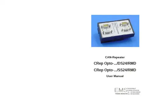
User Manual CRep O p t o-.../D S24/RMDCRep O p t o-.../SS24/RMDCAN-R ep eaterCRep Opto-.../D S24/RMD CRep Op t o-.../SS24/RMDUser M anu a l Documentation for CAN-Repeater CRep Opto-.../DS24/RMDand CRep Opto-.../SS24/RMD.Document version: V1.8Documentation date: August 28th, 2018No part of this document or the software described hereinmay be reproduced in any form without prior writtenagreement from EMS Dr. Thomas Wünsche.For technical assistance please contact:EMS Dr. Thomas WünscheSonnenhang 3D-85304 IlmmünsterTel. +49-8441- 490260Fax +49-8441- 81860Email: ************************Our products are continously improved. Due to this fact specifications maybe changed at any time and without announcement.FCC: This device complies with part 15 of the FCCRules. Operation is subject to the followingtwo conditions: (1) This device may not causeharmful interference, and (2) this device mustaccept any interferencereceived, includinginterference that may cause undesiredoperation.Sonnenhang 3D-85304 IlmmünsterTel +49-8441/490260 THOMAS WÜN S C H E F ax +49-8441/81860WARNING: CRep Opto hardware and software may not be used in applications where damage tolife, health or private property may resultfrom failures in or caused by these compo-nents.EM SUser Manual CRep O p t o-.../D S 24/RMD CRep O p t o-.../SS 24/RMD Documentation for CAN-Repeater CRep Opto-.../DS24/RMD and CRep Opto-.../SS24/RMD.Document version: V1.8Documentation date: August 28th, 2018No part of this document or the software described herein may be reproduced in any form without prior writtenagreement from EMS Dr. Thomas Wünsche.For technical assistance please contact:EMS Dr. Thomas Wünsche Sonnenhang 3 D-85304 Ilmmünster Tel. +49-8441- 490260 Fax +49-8441- 81860 Email: ************************Our products are continously improved. Due to this fact specificationsmaybe changed at any time and without announcement.FCC: This device complies with part 15 of the FCCRules. Operation is subject to the following two conditions: (1) This device may not cause harmful interference, and (2) this device must accept any interferencereceived, including interference that may cause undesiredoperation.WARNING: CRep Opto hardware and software may notbe used in applications where damage tolife, health or private property may resultfrom failures in or caused by these compo-nents.User ManualCRep Opto -.../SS24/RMDCRep Opto -.../DS24/RMD6 Appendix B 6.1 Instruction for Disposal Electronic Equipment Act (WEEE)EMS is selling its products exclusively to commercial customers. This is the reason why all devices are designed for commercial use and have to be disposed appropriately. In accordance to § 10 para. 2 clause 3 Electronic Equipment Act (WEEE) the disposal of EMS products is regulated the following way.The equipment must not be disposed at the public collection points. In accordance with the applicable law the disposal has to be done by thecustomer for own account. The same applies to products, which havebeen sold to third parties, if those parties do not take care of a disposal in accordance to the applicable law. As an alternative the products can be returned to EMS free of charge.6.2 FCC Statement NOTE: This equipment has been tested and found to comply with the limits for a Class A digital device, pursuant to Part 15 of the FCC Rules. These limits are designed to provide reasonable protection against harmful interference when the equipment is operated in a commercial environment. This equipment generates, uses, and can radiate radio frequency energy and, if not installed and used in accordance with the instruction manual, may cause harmfulinterference to radio communications. Operation of this equipment in a residential area is likely to cause harmful interference in whichcase the user will be required to correct the interference at his ownexpense.Contents THIS PAGE INTENTIONALLY LEFT BLANK Star topology with repeaters1Overview 11.1 Attributes11.2 General Description11.3 Ordering Information22Electrical Characteristics32.1 Absolute Limiting Values32.2 Nominal Values33Operating Instructions43.1 Layout and Pin Assignment43.2 Block Diagram CRep Opto DS .63.3 Block Diagram CRep Opto SS .74Dimensions95Appendix A105.1 Topology examples 106Appendix B116.1 Instruction for Disposal 1116.2 FCC Statement111THIS PAGE INTENTIONALLY LEFT BLANK5 Appendix A: Topology examplesStar topology with repeaters CAN busses should always be terminated on both ends, typi-cally using a 120Ohm termination resistor between CAN-Highand CAN-Low signal lines.LegendLine topology with repeatersTree topology with repeaters4DimensionsAll values in [mm].1 Overview1.1 Attributes• Protocol transparent CAN repeater• High throughput due to low latency • ISO 11898 compatible bus interfacewith galvanic decoupling of CAN segments• Connection complying to CiA DS102standard• Single or dual 12V-24V power supply • Extended error suppression1.2 General DescriptionThe compact CAN repeater CRep Opto trans- mits and amplifies signals transparent to the CAN protocol. Each of the two galvanically se- parated CAN connections has the physical be- haviour of a single bus node. CRep Opto per- mits a flexible design of the network topology. Star and tree structures can be implemen t ed as well as long stub lines. By the possibility to use a network structure that fits the application best a reduction of installation costs can be achieved.The maximum data rate in CAN networks, de- pending on signal propagation delays, can be increased, if CRep Opto is used to improve the network structure. An increase of the maxi- mum node count in a CAN network can be reached by splitting the network into subnets that are connected by CRep Opto. Each sub- net can apply the maximum number of CAN nodes permitted by the drivers output current. Where CAN signals have to be transmitted over long distances, CRep Opto can be used for signal conditioning. Galvanic decoupling of the bus segments allows to connect subnets with differing ground potential by CRep Opto. The integrated shut down capability in case of errors reduces the impact on intact bus seg- ments by defective segments for the most commonly occuring errors.CRep Opto can be obtained in two different versions: CRep Opto DS24 has to be supplied from both network sides, CRep Opto SS24 is only supplied on CAN1.1.3 Ordering Information12-02-10x-20 CRep I-.../DS24/RMDCAN repeater for rail mount application, galvanic separati- on, double sided supply 12-02-20x-20 CRep I-.../SS24/RMDCAN repeater for rail mount application, galvanicseparation, single sided supply 12-02-11x-20 CRep I-.../DS24/RMD-ETRCAN repeater for rail mount application, galvanic separation, double sidedsupply, extended temperature range 12-02-21x-20 CRep I-.../SS24/RMD-ETRCAN repeater for rail mount application, galvanic separation, single sidedsupply, extended temperature range(... inhibit t ime)over long distances, CRep Opto can be usedfor signal conditioning. Galvanic decoupling of the bus segments allows to connect subnets with differing ground potential by CRep Opto. The integrated shut down capability in case of errors reduces the impact on intact bus seg- ments by defective segments for the most commonly occuring errors.CRep Opto can be obtained in two differentversions: CRep Opto DS24 has to be supplied from both network sides, CRep Opto SS24 is only supplied on CAN1.1.3 Ordering Information12-02-10x-20 CRep I-.../DS24/RMDCAN repeater for rail mount application, galvanic separati- on, double sided supply 12-02-20x-20 CRep I-.../SS24/RMDCAN repeater for rail mount application, galvanicseparation, single sided supply12-02-11x-20 CRep I-.../DS24/RMD-ETRCAN repeater for rail mount application, galvanic separation, double sidedsupply, extended temperature range 12-02-21x-20 CRep I-.../SS24/RMD-ETRCAN repeater for rail mount application, galvanic separation, single sidedsupply, extended temperature range(... inhibit t ime)L o g i cL o g i cC A N _HC A N _HT r a n s c e i v e rT r a n s c e i v e rABC A N _LC A N _LR x L E DR x L E DD C /D C 5V24V5V+24VG N D3.3 Block Diagram CRep Opto SS4DimensionsAll values in [mm].L o g i cL o g i cC A N _HC A N _HT r a n s c e i v e rT r a n s c e i v e rABC A N _LC A N _L5V24V5V24V+24V+24VG N DG N D3.2Block Diagram CRep Opto DS ParameterMin Max Unit Storage temperature -20 +80 °C Operating temperature¹0 +60 °C Power supply voltage-100+35 V Voltage on signal lines-30+30VParameter Min TypMax Unit Currentconsumption¹ (no load) –30–mACurrentconsumption¹ (250kBit/s, 100% load)–40 –mAPower supply voltage 10 24 30 V Propagation delay–125200ns2 Electrical Characteristics2.1 Absolute Limiting ValuesAny (also temporary) stress in excess of the li- miting values may cause permanent damage on CRep Opto and connected devices.3Operating Instructions3.1 Layout and Pin AssignmentCRep Opto devices include 2 CAN segmentsfed to a male and a female plug of typeD-Sub 9. The plugs carry the CAN signals and the supply voltage.¹ Version ETR -20°C - +70°C2.2 Nominal ValuesAll values, unless otherwise specified, refer to a supply voltage of 2 4V and an environmental temperature of 20°C.CAN 1CAN RepeaterCRep I-5/SS24/RMDVersion 2.0EMS Dr. Thomas WünscheCAN 2¹ with 24V supply voltageCRep Opto-.../SS24/RMD 3Operating Instructions3.1 Layout and Pin AssignmentCRep Opto devices include 2 CAN segments fed to a male and a female plug of typeD-Sub 9. The plugs carry the CAN signals and the supply voltage. CAN 1CAN RepeaterCRep I-5/SS24/RMDVersion 2.0EMS Dr. Thomas WünscheCAN 2CRep Opto-.../DS24/RMD CRep Opto-.../SS24/RMDL o g i cL o g i cC A N _HC A N _HT r a n s c e i v e rT r a n s c e i v e rABC A N _LC A N _L5V24V5V24V+24V+24VG N DG N DThe following table shows the pin assignment of the D-Sub 9 plugs (male and female plug are connected internally):3.2 Block Diagram CRep Opto DSPin Name Function 2CAN_L CAN_Low bus line 3GNDGround 7CAN_HCAN_High bus line9V+CANPower supply 24VPlease notice that CRep Opto SS can only be supplied over CAN1.。

Course Description FortiClient EMSIn this course,you will learn how to use the FortiClient EMS feature,provisionFortiClient endpoints,FortiClient EMS Security Fabric integration,explore differenteditions of FortiClient,and deploy and configure ZTNA agent and endpoint securityfeatures.These fundamentals of the product will provide you with a solidunderstanding of how to deploy,manage and maintain endpoint security usingFortiClient EMS products.Product Versionl FortiClient EMS7.0.1l FortiClient7.0l FortiOS7.0.1Course Durationl Lecture time(estimated):6hoursl Lab time(estimated):4hoursl Total course duration(estimated):10hours/2daysWho Should AttendIT and security professionals involved in the management,configuration,and administration of FortiClient EMSendpoints used to secure devices for their organizations should attend this course.Participants should have a thorough understanding of endpoint solutions.CertificationThis course is intended to help you prepare for the FortiClient7.0specialist exam.This is one of the courses thatprepares you to take the NSE5certification exam.12/13/2021https://FortiClient EMS7.0Course DescriptionPrerequisitesA basic understanding of endpoint protection solutions. Agenda1.Introduction to FortiClient and FortiClient EMS2.Installation and Licensing3.FortiClient EMS configuration and Administration4.FortiClient Deployment5.FortiClient Provisioning Using FortiClient EMS6.ZTNA7.Diagnostics and TroubleshootingObjectivesAfter completing this course,you will be able to:l Understand the purpose of FortiClient EMS and identify FortiClient EMS componentsl Understand FortiClient EMS administration and database managementl Identify and explore FortiClient editionsl Understand FortiClient installationl Identify FortiClient features and settingsl Provision and deploy FortiClient using FortiClient EMSl Explore different deployment methods and typesl Understand and configure endpoint policies and profiles l Configure endpoint profile referencesl Understand the use of the ZTNAl Configure and deploy FortiClient ZTNA solutionl Understand compliance verification rules and manage tagsl Explore diagnostic tools and troubleshooting of FortiClient and FortiClient EMS Training Delivery Options and SKUs Instructor-Led TrainingIncludes standard NSE training content delivered in person onsite,or live online using a virtual classroom application.Training is delivered within public classesor as a private class.Private requests are scoped, quoted,developed,and delivered by Fortinet Training (minimum quantities apply).Use the following ILT Training SKU to purchase scheduled public classes of this course throughFortinet Resellers or Authorized Training Partners:FT-FCTSelf-Paced TrainingIncludes online training videos and resources throughthe NSE Training Institute library,free of charge.You can purchase on-demand lab access with interactive,hands-on activities using a purchase order (PO)through Fortinet Resellers or Authorized Training Partners.After you complete the purchase,you receive labaccess and the accompanying lab guide within the self-paced course.Use the following on-demand lab training SKU to purchase lab access using a PO:FT-FCT-LABSee Purchasing Process for more information about purchasing Fortinet training products.(ISC)2l CPE training hours:6l CPE lab hours:4l CISSP domains:Communication and Network Security Program Policies and FAQsFor questions about courses,certification,or training products,refer to Program Policy Guidelines or Frequently Asked Questions.。
攀枝花市委“两新组织”工委党建工作综合信息管理系统系统操作说明书文档编号:00335-D005-2012005版本编号:20121022-001一、OIMS 2012 运行环境硬件环境:a)CPU:英特尔奔腾4 1.2GHz及以上b)内存:1G及以上c)显示器:17寸及以上d)显示器分辨率:最低1024*768及以上系统及软件环境:e)Windows XP SP2或SP3f)Windows Server 2003g)Windows Vistah)Windows 7 (32位或64位)i)Office 2003及以上二、OIMS 2012 系统安装OIMS 2012 系统本身无需安装,前提是在需要运行OIMS 2012 系统的计算机上安装软件运行环境。
OIMS 2012 运行环境会随软件一同下发,将“OIMS 2012-运行环境.rar”压缩包解压到任意路径下安装即可,无需特别设置。
•在安装完毕OIMS 2012 运行环境后,即可将主程序的压缩包解压到任意路径下完成整个程序的部署。
•要完全使系统能够运行,还需要到上一级管理部门获取对应数据包,并拷贝到安装路径覆盖原文件夹即可完成数据初始化。
•如需运行OIMS 2012 系统直接双击执行安装路径下的OIMS2012.exe。
三、OIMS 2012 系统架构四、OIMS 2012 系统操作执行OIMS 2012 系统后,首先会要求进行用户验证。
a)用户名为本机构代码b)初始密码为666666(可在系统菜单的【用户管理】中进行修改)•OIMS 2012 系统主界面分为:菜单栏和窗口区域两部分•菜单栏分为5大类11个功能菜单。
五、OIMS 2012 系统操作-机构管理点击主界面菜单栏上的【机构管理】在左侧的机构树中选择对应的机构。
点击右侧的【新建】按钮在右侧下方的【新建单位】文本框中填入新建机构的名称。
点击右侧上方的【保存】按钮系统完成数据保存后,会自动导出新建机构的初始化数据包,选择该数据包的保存路径后点击【确定】按钮,系统将会在选定的路径下生成一个以新建机构编码开头的文件夹(内包含数据初始文件),连同系统的安装文件和运行环境文件一同拷贝给对应单位即可。
电子单多点测量软件EMS7.3.3简要说明书北京市普利门机电高技术公司电子单多点测量软件EMS7.3.3是专为普利门公司电子单多点探管配合使用的工程应用软件。
本说明书由三部分组成:首先说明多点测量数据库文件的组成;接着以流程图的形式说明EMS7.3.3软件如何在工程中使用及操作顺序;最后,对每个菜单命令进行功能说明。
系统主窗口一. 数据库文件的组成执行“文件/查看数据文件…”命令,即可打开下面的“查看测量数据文件窗口”,从目录树中可以看到:所有数据库文件都存储在名为“多点测量数据”文件夹中。
在“多点测量数据”文件夹中是以各个工程名命名的文件夹,如:“多点测量工程0001”、“多点测量工程0002”、“多点测量工程0003”、…要求一个打井工程只对应一个工程名。
在工程名文件夹中包含一个名为“多点测量信息”文件,此文件记录着井名、区块、油田、公司、井队、操作者…等工程信息。
工程名文件夹中还包含多点测量记录名命名的文件夹,自文件夹名是系统根据测量数据下载次数自动按顺序命名的如“多点测量记录0001”\“多点测量记录0002”\“多点测量记录0003” …。
每个多点测量记录文件夹中包括5个文件:“下井准备”文件、“探管参数”文件、“原始数据”文件、“测量数据”文件、“测量报告”文件。
所有这些文件是数据库格式。
“下井准备”文件:记录探管测量时的“启动延时”、“间隔延时”、“测量方式”等信息;“探管参数”文件:记录所使用探管的校正参数,此参数是出厂时存储在探管中的,在下载测量数据时,与“原始数据”文件、“测量数据”文件一起生成的。
“原始数据”文件:此文件记录代表传感器输出的脉冲宽度值,单位为微秒。
“测量数据”文件:此文件记录整个测量过程的井斜、方位、工具面…等打井参数。
图1二.EMS7.3.3软件如何在工程中使用及操作顺序三. 菜单命令功能说明图2“文件(F)”该菜单项包含下拉菜单如图2,用于完成工程文档、下井记录选择、数据文档查看及退出软件等功能。
EMS:效率度量系统用户说明书内容1 介绍2准备投入产出数据2.1 使用微软Excel文件2.2 使用文本文件2.3 非自由处置的投入和产出3准备权重限制3.1 使用微软Excel文件3.2 使用文本文件4 开始EMS和调入数据5 运行一个DEA模型5.1 准备结果格式5.2 选择技术结构5.3 选择效率测度5.4 高级模型选择6 结果7 致谢8声明1 介绍效率度量系统(EMS)是基于微软Windows 9x/NT系列的计算数据包络分析效率测度的软件。
这本手册的目的就是介绍这个软件的应用,并非介绍DEA,关于DEA你可以参考下列书籍:• H. O. Fried, C. A. K. Lovell, and S. Schmidt (1993), The measurement of productive e_ciency: Techniques and applications, OxfordUniversity Press, New York• R. F¨are, S. Grosskopf, and C. A. K. Lovell (1994), Pr oduction Frontiers,Cambridge University Press, Cambridge• A. Charnes, W. W. Cooper, A. Y. Lewin, and L. M. Seiford (1994), Data Envelopment Analysis: Theory, Methodology, and Application, Kluwer Academic Publishers, Dordrecht• W. W. Cooper, L. M. Seiford, and K. Tone (2000), Data Envelopment Analysis: A Comprehensive Text with Models, Applications, Referencesand DEASolver Software, Kluwer Academic Publishers, Norwell,Massachusetts关于EMS的最新消息、下载和补丁,你可以访问EMS主页:http://www.wiso.uni-dortmund.de/lsfg/or/scheel/ems/ EMS使用由Csaba M´esz aros编写的计算数值的线性规划求解软件BPMPD,(来源:),它采用的是内点法。
如果在下面的章节中你还有问题没有得到回答或如果你有更好的建议,请发送邮件到:H.Scheel@wiso.uni-dortmund.de2 准备投入产出数据效率评价中首先或许是最困难的是决定应该包括那些投入产出数据。
EMS接受微软的Excel文件格式和文本格式。
另外,对于“标准的”投入和产出,EMS 能够处理“非任意处置的”投入和产出,如(数据不被决策单元控制)。
下一部分将描述如何为EMS准备数据文件。
你的分析的大小限于你的计算机内存,理论上对决策单元、投入和产出指标的个数没有限制,虽然对于大规模数据代码没有优化,但我们成功求解了5000个决策单元和40个投入和产出指标的问题。
(如果您有处理过更大规模数据的经验请通知我们)。
2.1 使用微软Excel文件EMS 接受 Excel 97或更老一点的(*.xls)文件。
投入产出数据应当放在一个表内。
不要在工作表内用公式,表内只包含数据。
EMS需要下列数据格式:工作表的名称必须是“Data”第一行包含投入产出名称,首先是投入,然后是产出投入的名字必须包含字符串“{I}”.产出的名字必须包含字符串“{O}”.第一列包含决策单元的名字2.2 使用文本文件对于那些喜欢其他电子制表软件而不是微软Excel的用户,EMS也接受平常的文本文件(*.txt),为了正确的读取文本文件需要schema.ini文件,它包含一些格式信息,使用文本文件下列下面的操作是必须的:将schema.ini放在你要使用的文本文件相同的目录内。
将schema.ini改变为“[Yourfile.txt]”, Yourfile是你的文件名。
包含投入产出数据的文本文件应满足下列条件:列由Tabs.键分隔,两列之间只能有一个Tabs.键,而在文件的其他地方没有Tabs.键(如结尾),你可以通过文本编辑器将Tabs.键变为“可视”来进行检查。
投入的名字包含字符串“{I}”.产出的名字包含字符串“{O}”.第一列包含决策单元的名字比较例子EXAMPLE.TXT文件。
.2.3 非任意处置的投入和产出EMS接受非任意数据,只要数据文件中相应输入名称包含“{IN}”而非“{I}”,或相应输出名称包含“{ON}”而非“{O}”。
EMS 计算效率评价值(即与有效前沿面的差距)时,并不改变非自由处置数据的值。
也就是说,只计算非自由处置固定输入输出为“正常”(任意)情况下的差距。
文献:EMS利用了R. D. Banker和R. C. Morey的思想(1986), 外部固定输入输出条件下的效率分析,运筹学,34, 513–521。
也参考了下面这篇文章的总的看法:M. Staat (1999), 处理非任意变量的若干方法:效率分数及解释的隐含意义,In G. Westermann(编辑),服务领域的数据包分析,23–50页, Gabler, Wiesbaden。
3.设定权重约束条件你可以定义权重约束公式W(p, q) ≥ 0, 这里 p 指输入权重向量, q 指输出权重向量(或影子价格)。
从而可以合并“锥面比率”约束条件和“可行域”约束条件。
举例:假设有3个输入和2个输出,若约束条件是 p1≥ p2,那么权重约束矩阵W 中的相应行就是 (1 −1 0 0 0);如果另外代入边际比率约束如 0.3≤q1/q2 ≤3,可以将之转化为两个约束条件:q1 −0.3q2 ≥0 和 -q1 + 3q2≥ 0,对应矩阵W中的行 (0 0 0 1−0.3)和 (00 0−1 3)。
这样,本例得出矩阵W如下:如同输入输出数据一样,EMS 接受MS 表格和TXT 文本文件中的权重约束数据W 。
3.1 使用 MS 表格文件EMS 接受Excel97(或更老版本)文件(*.xls)。
权重数据应汇总在一个工作表中。
不要使用表中公式,它仅包含纯数据,其他一概不包含。
EMS 需要以下的数据格式:• 工作表名称必须是“权重”。
(它可以与其他表如“数据”表等包含在同一文件内,也可另选其他文件)• 第一行(输入输出名称)必须与相应的数据表一致• 第一列包含每个约束的名称比较:范例文件EXAMPLE.XLS3.2 使用文本文件如果文本文件中有W, 那就要象处理输入输出数据那样:首先把schema.ini 文件列入文本文件目录并修改,如:把“[Yourweightfile.txt]”换成你自己的文件名称。
包含W 的文本文件应确保符合下列条件:• 列之间用制表符分开• 第一行(输入输出名称)必须与相应的输入输出数据文件一致• 第一列包含每个约束的名称比较:范例文件 WEIGHTS.TXT.文献:参考主要观点:R. Allen, A. Athanassopoulos, R. Dyson 和 E. Thanassoulis (1997), 数据包分析中的权重约束和权值判断:演进、发展和未来方向,运筹学年报,73, 13–34。
4 启用EMS 和数据调入如果已经准备好了上述Excel 和(或)文本文件格式的数据,你可以点击启1 −1 0 0 00 0 0 1 0.3 0 0 0 −1 3用程序文件夹中的 EMS 。
现在将EMS与数据相联:输入输出数据可以按Ctrl+0调入。
如果你选择了合适的文件名,那么EMS也会搜索并与文件相联。
对于有上千个DMU 的大型DEA 评价,可能会需要几秒钟。
联接能成功:• 如果文件名出现在状态栏里(在EMS 窗口底部)并且• 沙漏标志消失EMS 不显示你的数据!如果想编辑数据,应打开Excel 中的或文本编辑器里的数据文件并进行编辑。
保存修改内容(不必关闭文件)并按(Ctrl+0) 再次向EMS 调入。
EMS 通常从硬盘上调入文件版本。
按Ctrl+W 来调入包含矩阵W 的文件(菜单文件→调入权重约束),当文件成功调入后,文件名出现在状态栏里(如同输入输出数据文件)。
5 运行DEA 模型运行DEA 模型前,确认bpmpd.par 文件与数据文件在同一文件夹内!5.1 设计计算结果的格式Ctrl+F (菜单 DEA→格式) 将出现在格式对话框里。
在这儿,你可以定义小数点后的位数,EMS 计算出的结果将出现在结果表中。
进而,你可以决定是否:纯投入产出权重(影子价格)pi 和 qj 应当被显示(选择纯权重)或“实际的输入和输出”,权重同输入和输出进行了相乘pi · x i0, qj · y j0(选择的实际输入输出)上面这些应当在结果表中显示出来。
4. 2选择一个技术结构Ctrl+M (菜单DEA ! Run model)将显示一个对话框,你可以在那里限定你所计算的模型凸的和非凸包络规模收益不变,可变,非增或非减5.3选择一个效率度量一个效率测度量化了到技术有效前沿面的的距离。
EMS 可以计算面向投入的、面向产出的和非面向的距离。
一个面向投入的测度量化了在保持产出不变情况下投入的必要减少量,对称的,一个面向产出的测度量化了在保持投入不变情况下产出投入的增加量。
一个非面向的量化了同时的投入减少和产出的增加。
实际中应用选择哪个标准主要取决于3个标准:“初始” 的解释,如关于投入产出效率值的意义对偶解释,如关于投入产出价格效率值的意义效率度量的公里化特性:如单调性,单元不可变性,效率的指示性和一致性。
大多数度量都同这些标准相似,当测度如下定义时,在这本手册里这些不同只是简单的提到。
T 指效率,(Xk, Y k)指被评价的决策单元的投入产出数据。
径向的:这种测度(a.k.a. Debreu-Farrell-测度或 CCR/BCC 测度的径向部分)指所有的相关因素按相同比例的必要提高量。
它的面向有一个很好的价格解释(成本减少/价格增加)但它并不指Koopmans 效率非面向的:})1(,)1(|max{T Y X k k ∈+-θθθ面向投入的: },|min{T Y X k k ∈θθ面向产出的:},|max{T Y X k k ∈φϕ参考文献 M. J. Farrell (1957), The measurement of productive efficiency, Journal of the Royal Statistical Society, Series A, 120(3), 253–290.额外的:这种测度量化了绝对提高的最大和(投入减少或产出增加由松弛变量度量)它有价格解释(如实际的和最大的利益的差距)和Koopmans 效率指示作用,但它对于测度单元是不变的。