转向架毕业设计外文翻译
- 格式:wps
- 大小:2.70 MB
- 文档页数:20

兰州交通大学车辆工程专业毕业论文30t轴重货车转向架摇枕的结构及设计摘要随着我国铁路运输向高速和重载方向发展,转向架摇枕的运用条件日趋苛刻。
因此,研究重载运输条件下的摇枕结构及其性能变得尤为重要。
本文通过国内外重载运输的发展现状的了解,分析了国内外现有重载货车转向架的结构特点和性能。
首先对我国30t轴重转向架进行了结构选型,初步确定了适应我国国情的30t轴重货车转向架的基本结构型式。
重点对该转向架的摇枕的结构进行自主设计与分析。
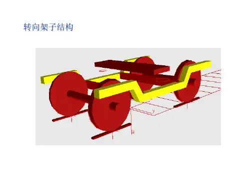
运用SolidWorks建立30t轴重货车转向架摇枕的三维模型,并且详细介绍了该转向架摇枕的结构特点及设计步骤,其中包括了外壁和内部筋板厚度、排水口、漏沙孔等工艺孔、摇枕斜楔、15旁承台座、16弹簧承台、心盘部位、摇枕吊耳。
然后对该摇枕进行了有限元应力分析,然后根据分析结果确定摇枕的薄弱地方并进行改进,最终设计得到满足强度要求,并有足够抗疲劳性能的转向架摇枕。
关键词:重载货车;转向架;摇枕;设计;有限元分析AbstractWith the development of railway transportation in China to high speed and heavy, truck bolster conditions using the increasingly harsh.Therefore, studying under heavy haul bolster structure and performance has become particularly important. The current development status at home and abroad through the heavy haul transportation understanding, analysis of the structure characteristics and performance of the existing heavy truck frame at home and abroad to .The first of China's 30t axle load bogie structure selection, initially identified the basic structure frame of the axle load 30t China steering. The focus of the steering structure bolster frame of independent design and analysis.Use SolidWorks to set up 30t axle load truck steering frame bolster 3D model, and introduces the structure characteristics and design steps of steering frame bolster, including the outer and inner rib plate thickness, drains, drain sand hole technology of hole, bolster wedge, a side bearing pedestal, spring seat, center plate position, swing hanger lug. Then the bolster the finite element stress analysis, then bolster weak place and determined according to the analysis results, the final design can meet the strength requirements, and has enough fatigue performance of the bogie bolster.Key words: heavy-duty freight car; Bogie;Bogie Bolster; Design;The finite element analysis目录1 绪论------------------------------------------------------------------------------------------------- 11.1 选题背景---------------------------------------------------------------------------------- 11.2 国外重载车辆的现状------------------------------------------------------------------- 11.3 我国近年来重载车辆现状------------------------------------------------------------- 21.4 本文主要工作---------------------------------------------------------------------------- 22 国内外大轴重转向架的现状------------------------------------------------------------------- 32.1 国外大轴重转向架---------------------------------------------------------------------- 32.2 我国国内及出口大轴重转向架 ------------------------------------------------------ 53 转向架的结构选型----------------------------------------------3.1 转向架选型原则------------------------------------------------------------------------- 83.2 转向架结构特点------------------------------------------------------------------------- 84 转向架摇枕的设计------------------------------------------------------------------------------104.1 大轴重转向架载重分析和损伤部位探究 -----------------------------------------104.2 转向架摇枕的三维结构设计 --------------------------------------------------------124.2.1 总体结构设计------------------------------------------------------------------124.2.2 外壁和内部筋板厚度的设计 -----------------------------------------------134.2.3 排水口、漏沙孔等工艺孔的设计 -----------------------------------------144.2.4 摇枕斜楔的设计---------------------------------------------------------------154.2.5 旁承台座的设计---------------------------------------------------------------164.2.6 弹簧承台的设计---------------------------------------------------------------174.2.7 心盘部位的设计---------------------------------------------------------------174.2.8 摇枕吊耳的设计---------------------------------------------------------------184.2.9 棱角的圆弧过渡设计 --------------------------------------------------------195 转向架摇枕的有限元分析---------------------------------------5.1.1 有限元求解问题的思路及方法 --------------------------------------------215.1.2 转向架摇枕承受载荷情况分析 --------------------------------------------225.1.3 转向架摇枕使用Simulation进行有限元分析---------------------------235.1.4 转向架改进措施---------------------------------------------------------------275.1.5 本章小结------------------------------------------------------------------------27结论 ---------------------------------------------------------------------------------------------------28 致谢 ---------------------------------------------------------------------------------------------------29 参考文献---------------------------------------------------------------------------------------------301 绪论1.1 选题背景我们国家自从改革开放到现在,随着国民经济的一直深入的发展和人民生活水平的显著提高,我们对货物运输效率的要求也是越来越高了。
Z S T U Zhejiang Sci-Tech University 本科毕业设计Bachelor’S THESIS论文题目:机车转向架助推器设计专业班级:姓名学号:指导教师:递交日期: 2013年5月29日浙江理工大学机械与自动控制学院毕业设计诚信声明我谨在此保证:本人所做的毕业设计,凡引用他人的研究成果均已在参考文献或注释中列出。
设计说明书与图纸均由本人独立完成,没有抄袭、剽窃他人已经发表或未发表的研究成果行为。
如出现以上违反知识产权的情况,本人愿意承担相应的责任。
声明人(签名):年月日摘要大型工件、物品的搬运常采用助推器辅助搬运完成作业,主要有机械式、气动式、电动式、液压式等,其工作性能各有优劣,有特定的适用场合。
铁路机车或车辆检修维护时的移动一直采用牵引机车或牵车机构牵引,而牵引机车一般为内燃机车,不适合在机车或车辆检修要求越来越高的库内牵引机车用,而牵车机构一般为链式传输机构,其安装空间需要利用轨道中间的部分空间,且建造成本高、运行不稳定、维护成本较高和驱动电机的防水防潮功能要求较高,使用效果一直不理想。
本文拟在综合分析比较现有搬运助推器的工作原理、组成结构的基础上,通过分析机车转向架与助推器的受力作用情况,运用ADAMS软件对助推器的执行机构进行建模和运动仿真,确定了执行杆件的运作方式和受力作用情况,进一步校核各部件,设计出一种用于搬运不同规格机车转向架、适合机车车间工作条件的低耗高效便携式助推器。
结构简单,方便组装,方便工人操作的便携式机车牵车装置,为机车检修时方便进出检修库用。
关键词:助推器;高效;便捷;ADAMS;仿真AbstractLarge workpiece and goods' transport often use boosters to help to finish the work.The main means are mechanical, pneumatic, electric, hydraulic.Every means has its own advantages and disadvantages and every means is used in its special appropriate occasion . When the railway locomotive and vehicle are in maintenance,it has often been using traction locomotives or traction mechanism for moving. But the traction locomotive is usually a kind of diesel locomotives.It is not suitable for the traction of locomotive,with the request more and more high in locomotive and vehicle maintenance. The traction mechanism is usually a kind of chain transmission mechanism.The middle part of the space of the orbit is required for the installation space , with high construction costs,unstable operation,high maintenance costs and the higher requirements for drive motors' waterproof function.So the using effect has not been ideal.This article is on the comprehensive analysis of the working principle and existing boosters' structure. By analyzing the force condition of the locomotive bogie and the booster,using the Adams software for modeling and motion simulation of the executive mechanism of the booster. So the executive members' operation mode and the force function are determined, further checking other parts, designing a kind of portable booster with high efficiency and low consumption for the transport of different specifications of bogies. And it is suitable for the locomotive workshops' working conditions. It is a kind of portable traction device with simple structure, convenient assembly and convenient operation ,for convenient in or out of the maintenance bases when the railway locomotive and vehicle is in maintenance.Key words: Booster; High Efficiency; Portable; Adams; Motion Simulation目录摘要Abstract第1章绪论 (1)1.1转向架助推器研究背景 (2)1.2现有助推器类型 (2)1.2.1滚轮助推器 (2)1.2.2抬升式助推器 (4)1.2.3多功能助推器 (5)1.3虚拟样机技术 (6)1.4本论文主要研究内容 (7)第2章撬棍式助推器研究思路和方案 (8)2.1研究思路 (8)2.1.1三种助推器的比较 (8)2.1.2 撬棍式助推器方案 (8)2.2执行机构受力分析 (9)2.2.1执行机构位置分析 (10)2.2.2齿轮传动比确定 (10)2.2.3机构受力分析 (11)2.3电机选择 (13)2.4结论 (13)第3章基于Adams的建模和仿真 (15)3.1 Adams 软件介绍 (15)3.1.1 Adams 软件的概述 (15)3.1.2 ADAMS仿真步骤 (15)3.2 执行机构自由度分析 (16)3.3 凸轮轮廓线的设计 (17)3.3.1建立模型 (17)3.3.2仿真 (18)3.3.3确定轮廓曲线 (18)3.4 执行机构建模与仿真 (19)3.4.1建立模型 (19)3.4.2添加约束 (20)3.4.3仿真 (21)3.4.4仿真结果后处理 (21)3.5结论 (24)第4章结构设计 (26)4.1 整体结构简图 (26)4.2各部件校核 (26)4.2.1齿轮设计与校核 (26)4.2.2链传动设计 (30)4.2.3轴的结构设计和强度校核 (31)4.2.4轴承选择 (35)第5章总结 (37)5.1 总结 (37)5.2 设计的不足之处 (37)5.3 个人体会 (37)参考文献 (39)致谢 (40)第1章绪论1.1转向架助推器研究背景进入21世纪,我国的城市轨道交通方兴未艾。

LathesLathes are machine tools designed primarily to do turning, facing and boring, Very little turning is done on other types of machine tools, and none can do it with equal facility. Because lathes also can do drilling and reaming, their versatility permits several operations to be done with a single setup of the work piece. Consequently, more lathes of various types are used in manufacturing than any other machine tool.The essential components of a lathe are the bed, headstock assembly, tailstock assembly, and the leads crew and feed rod.The bed is the backbone of a lathe. It usually is made of well normalized or aged gray or nodular cast iron and provides s heavy, rigid frame on which all the other basic components are mounted. Two sets of parallel, longitudinal ways, inner and outer, are contained on the bed, usually on the upper side. Some makers use an inverted V-shape for all four ways, whereas others utilize one inverted V and one flat way in one or both sets, They are precision-machined to assure accuracy of alignment. On most modern lathes the way are surface-hardened to resist wear and abrasion, but precaution should be taken in operating a lathe to assure that the ways are not damaged. Any inaccuracy in them usually means that the accuracy of the entire lathe is destroyed.The headstock is mounted in a foxed position on the inner ways, usually at the left end of the bed. It provides a powered means of rotating the word at various speeds . Essentially, it consists of a hollow spindle, mounted in accurate bearings, and a set of transmission gears-similar to a truck transmission—through which the spindle can be rotated at a number of speeds. Most lathes provide from 8 to 18 speeds, usually in a geometric ratio, and on modern lathes all the speeds can be obtained merely by moving from two to four levers. An increasing trend is to provide a continuously variable speed range through electrical or mechanical drives.Because the accuracy of a lathe is greatly dependent on the spindle, it is of heavy construction and mounted in heavy bearings, usually preloaded tapered roller or ball types. The spindle has a hole extending through its length, through which long bar stock can be fed. The size of maximum size of bar stock that can be machined when the material must be fed through spindle.The tailsticd assembly consists, essentially, of three parts. A lower casting fits on the inner ways of the bed and can slide longitudinally thereon, with a means for clamping the entire assembly in any desired location, An upper casting fits on the lower one and can be moved transversely upon it, on some type of keyed ways, to permit aligning the assembly isthe tailstock quill. This is a hollow steel cylinder, usually about 51 to 76mm(2to 3 inches) in diameter, that can be moved several inches longitudinally in and out of the upper casting by means of a hand wheel and screw.The size of a lathe is designated by two dimensions. The first is known as the swing. This is the maximum diameter of work that can be rotated on a lathe. It is approximately twice the distance between the line connecting the lathe centers and the nearest point on the ways, The second size dimension is the maximum distance between centers. The swing thus indicates the maximum work piece diameter that can be turned in the lathe, while the distance between centers indicates the maximum length of work piece that can be mounted between centers.Engine lathes are the type most frequently used in manufacturing. They are heavy-duty machine tools with all the components described previously and have power drive for all tool movements except on the compound rest. They commonly range in size from 305 to 610 mm(12 to 24 inches)swing and from 610 to 1219 mm(24 to 48 inches) center distances, but swings up to 1270 mm(50 inches) and center distances up to 3658mm(12 feet) are not uncommon. Most have chip pans and a built-in coolant circulating system. Smaller engine lathes-with swings usually not over 330 mm (13 inches ) –also are available in bench type, designed for the bed to be mounted on a bench on a bench or cabinet.Although engine lathes are versatile and very useful, because of the time required for changing and setting tools and for making measurements on the work piece, thy are not suitable for quantity production. Often the actual chip-production tine is less than 30% of the total cycle time. In addition, a skilled machinist is required for all the operations, and such persons are costly and often in short supply. However, much of the operator’s time is consumed by simple, repetitious adjustments and in watching chips being made. Consequently, to reduce or eliminate the amount of skilled labor that is required, turret lathes, screw machines, and other types of semiautomatic and automatic lathes have been highly developed and are widely used in manufacturing.2 Numerical ControlOne of the most fundamental concepts in the area of advanced manufacturing technologies is numerical control (NC). Prior to the advent of NC, all machine tools ere manually operated and controlled. Among the many limitations associated with manual control machine tools, perhaps none is more prominent than the limitation of operator skills. With manual control, the quality of the product is directly related to and limited to the skills of the operator. Numerical control represents the first major step away from human control of machine tools.Numerical control means the control of machine tools and other manufacturing systems through the use of prerecorded, written symbolic instructions. Rather than operating a machine tool, an NC technician writes a program that issues operational instructions to the machine tool. For a machine tool to be numerically controlled, it must be interfaced with a device for accepting and decoding the programmed instructions, known as a reader.Numerical control was developed to overcome the limitation of human operators, and it has done so. Numerical control machines are more accurate than manually operated machines, they can produce parts more uniformly, they are faster, and the long-run tooling costs are lower. The development of NC led to the development of several other innovations in manufacturing technology:Electrical discharge machining,Laser cutting,Electron beam welding.Numerical control has also made machine tools more versatile than their manually operated predecessors. An NC machine tool can automatically produce a wide of parts, each involving an assortment of widely varied and complex machining processes. Numerical control has allowed manufacturers to undertake the production of products that would not have been feasible from an economic perspective using manually controlled machine tolls and processes.Like so many advanced technologies, NC was born in the laboratories of the Massachusetts Institute of Technology. The concept of NC was developed in the early 1950s with funding provided by the U.S. Air Force. In its earliest stages, NC machines were able to made straight cuts efficiently and effectively.However, curved paths were a problem because the machine tool had to be programmed to undertake a series of horizontal and vertical steps to produce a curve. The shorter the straight lines making up the steps, the smoother is the curve, Each line segment in the steps had to be calculated.This problem led to the development in 1959 of the Automatically Programmed Tools (APT) language. This is a special programming language for NC that uses statements similar to English language to define the part geometry, describe the cutting tool configuration, and specify the necessary motions. The development of the APT language was a major step forward in the fur ther development from those used today. The machines had hardwired logic circuits. The instructional programs were written on punched paper, which was later to be replaced by magnetic plastic tape. A tape reader was used to interpret the instructions written on the tape for the machine. Together, all of this represented a giant step forward in the control of machine tools. However, there were a number of problems with NC at this point in its development.A major problem was the fragility of the punched paper tape medium. It was common for the paper tape containing the programmed instructions to break or tear during a machining process. This problem was exacerbated by the fact that each successive time a part was produced on a machine tool, the paper tape carrying the programmed instructions had to be rerun through the reader. If it was necessary to produce 100 copies of a given part, it was also necessary to run the paper tape through the reader 100 separate tines. Fragile paper tapes simply could not withstand the rigors of a shop floor environment and this kind of repeated use.This led to the development of a special magnetic plastic tape. Whereas the paper carried the programmed instructions as a series of holes punched in the tape, the plastic tape carried the instructions as a series of magnetic dots. The plastic tape was much stronger than the paper tape, which solved the problem of frequent tearing and breakage. However, it still left two other problems.The most important of these was that it was difficult or impossible to change the instructions entered on the tape. To made even the most minor adjustments in a program of instructions, it was necessary to interrupt machining operations and make a new tape. It was also still necessary to run the tape through the reader as many times as there were parts to be produced. Fortunately, computer technology became a reality and soon solved the problems of NC associated with punched paper and plastic tape.The development of a concept known as direct numerical control (DNC) solved the paper and plastic tape problems associated with numerical control by simply eliminating tape as the medium for carrying the programmed instructions. In direct numerical control, machine tools are tied, via a data transmission link, to a host computer. Programs for operating the machine tools are stored in the host computer and fed to the machine tool an needed via the data transmission linkage. Direct numerical control represented a major step forward over punched tape and plastic tape. However, it is subject to the same limitations as all technologies that depend on a host computer. When the host computer goes down, the machine tools also experience downtime. This problem led to the development of computer numerical control.3 TurningThe engine lathe, one of the oldest metal removal machines, has a number of useful and highly desirable attributes. Today these lathes are used primarily in small shops where smaller quantities rather than large production runs are encountered.The engine lathe has been replaced in today’s production shops by a wide variety of automatic lathes such as automatic of single-point tooling for maximum metal removal, andthe use of form tools for finish on a par with the fastest processing equipment on the scene today.Tolerances for the engine lathe depend primarily on the skill of the operator. The design engineer must be careful in using tolerances of an experimental part that has been produced on the engine lathe by a skilled operator. In redesigning an experimental part for production, economical tolerances should be used.Turret Lathes Production machining equipment must be evaluated now, more than ever before, this criterion for establishing the production qualification of a specific method, the turret lathe merits a high rating.In designing for low quantities such as 100 or 200 parts, it is most economical to use the turret lathe. In achieving the optimum tolerances possible on the turrets lathe, the designer should strive for a minimum of operations.Automatic Screw Machines Generally, automatic screw machines fall into several categories; single-spindle automatics, multiple-spindle automatics and automatic chucking machines. Originally designed for rapid, automatic production of screws and similar threaded parts, the automatic screw machine has long since exceeded the confines of this narrow field, and today plays a vital role in the mass production of a variety of precision parts. Quantities play an important part in the economy of the parts machined on the automatic screw machine. Quantities less than on the automatic screw machine. The cost of the parts machined can be reduced if the minimum economical lot size is calculated and the proper machine is selected for these quantities.Automatic Tracer Lathes Since surface roughness depends greatly on material turned, tooling , and feeds and speeds employed, minimum tolerances that can be held on automatic tracer lathes are not necessarily the most economical tolerances.In some cases, tolerances of 0.05mm are held in continuous production using but one cut . groove width can be held to 0.125mm on some parts. Bores and single-point finishes can be held to 0.0125mm. On high-production runs where maximum output is desirable, a minimum tolerance of 0.125mm is economical on both diameter and length of turn.车床车床主要是为了进行车外圆、车端面和镗孔等项工作而设计的机床。
Automobile Transmissions and Power Steering Automobiles, trucks, buses, and tractors all depend on transmissions to deliver power from the engine to the wheels, The gasoline and diesel engines that power these vehicles cannot be connected directly to the wheels, because the engines must keep turning at a certain seed to keepfrom stalling. Also, different amount of torque (turning force) must be delivered to the wheels atdifferent times. A large amount of force is needed to get a car moving from a standstill. Less force is needed to keep the car moving once it is rolling. Going up a hill of driving at high speed requires still other amount of force. It is the job of the transmission to deliver the particularamount of force that is needed. The transmission also allows a motor vehicle to back up-----gasoline and diesel engines can run in only one direction, but the transmission can reverse thedirection of the force. And when a car stops, the transmission lets the engine keep running without moving the wheels.The heart of any transmission——even an automatic one—is a set of gears. Gears do notchange the power of an engine, but they can increase the torque by decreasing the speed. They canalso increase the speed by decreasing the torque.The automobile transmission uses a series of gears which enables the engine to continue tovehicle’’s speed is altered. Setting an automobile in operate at maximum efficiency when the vehiclevehicle’’s weight. This motion requires a large amount of power to overcome the inertia of the vehicleprocess requires high engine speed, needed for high power, and a gradual increase in a vehicle’sspeed to avoid a jerky start. To do this, a low gear ratio is allows the crankshaft to revolve several times in order to turn the real axle once. The low gear ratio is used for starting, climbing steep slops, and other situations in which maximum power is required .As power needs are reduced, a second, higher gear ratio is used which rotates the rear axle with fewer revolutions of the crankshaft. As the car’s speed increases, successively higher gear ratios are used until the drive from the engine to the rear wheels passes through the transmission without reduction. Two principle types of transmission are used, manual and automatic.The manual transmission system permits the driver to select the desired gear ratio bymanipulating a shift lever. Besides the forward speed gears, additional gearing is incorporated topermit the vehicle to operate in reverse. Manually operated passenger car transmission used in the United States and Canada usually have there speeds forward and one in reverse. Trucks, tractors, buses, and other heavy-duty vehicles have as many as 10 forward speeds and 2 in reverse. These units are basically five-speed transmissions with a two-speed auxiliary gearbox. Transmission that are to be shifted with the vehicle in motion incorporate synchromesh units to prevent gears from clashing as they are meshed. The synchromesh unit synchronizes the speed of the gears so that they revolve at the same speed as they slide into engagement.The automatic transmission system changes gear ratios automatically in response to changesin engine speed or throttle setting. The use of automatic transmissions increased tremendouslyafter World War Ⅱ, and they are installed in more than half of the automobile produced in the United States. Automobiles equipped with an automatic transmission have a control lever which allows the driver to select neutral, low, drive, and reverse. The engine is started in neutral, and the lever is moved to “drivedrive”” position the drive”” for normal operation when moving forward. In “drivevehicles can accelerate from rest to maximum speed by simply depressing the accelerator. Thelow”” position prevent the transmission from shifting out of the lower gear ratios.“lowIt is used for climbing steep grades, in mud, or at other tomes when maximum power ispark”” position, which locks the transmission to prevent a parked car needed. Some units have a “parkfrom rolling. The automatic transmission makes it easier to drive a car, but it is less efficient than a manually shifted unit and increase gasoline consumption. For this reason, the automatic transmission is not as common in Europe, where economy of operation is a prime sales factor.Four basic types of automatic transmissions have been developed to the point where they have been installed in production vehicles. The first consists of a standard mechanical transmission and clutch which is automatically shifted by pneumatic, hydraulic or electric power units. The second type uses a hydraulic torque converter plus a planetary gear system to increase engine torque. The third system combines a hydraulic coupling with an automatically shifted mechanical gearbox to provide torque amplification. The fourth type uses one or more stages of hydraulic torque conversion to provide torque multiplication.Automatic transmission shift in response to signals from speed sensing and throttle position sensors. The units incorporating hydraulic torque converters use the hydraulic fluid, under pressure, to engage and disengage planetary gear trains.Power steering system 也是汽车重要的一部分,The car of today is larger and heavier than earlier cars; the tyres are wider, further apart and inflated to lower pressures .In addition, the trend of development has been to place more than half the weight on the front wheels, especially the weight of the engine , which itself is larger and heavier than in the early days.To make cars easier to steer, the gear ratio in the steering box at the end of the steering column was changed to that turning the wheel required less torque, but this increased the number of turns of the steering wheel required on modern cars without power steering compared to 2.5 or 3 turns for cars built before 1940. Modern cars with power steering only require about three turns.Power assisted steering was first developed in the 1920s; one of the first devices was developed by an engineer at Pierce Arrow, an American make of luxury cars. The Cadillac division of General Motors was going to offer power steering as optional equipment on some models in the early 1930s, but the depression interfered with development. During World War Ⅱ power steering was fitted to military vehicles; in 1952 Chrysler began offering it , and it is now standard equipment on many of the biggest American cars .Electric devices were tried , but power steering today is always hydraulic , with oil pressure of perhaps 1000 psi (70kg/cm2) maintained by a pump driven by the engineer of the car . The system is a servomechanism, or servo loop, which makes a correction to compensate for the torque applied to the steering wheel by the driver. It consists of an actuator and a control valve. The actuator is a hydraulic cylinder with a piston, or ram, which is free to travel in either direction from the center. The function of the control valve is to respond to the torque from the steering wheel by actuating smaller valves at each end of the cylinder. The system is designed to assist the steering linkage, rather than to replace it, and it does not do all of the work of steering , but leaves some of it for the driver. Thus if the hydraulics fail the car can still be steered , though with greater effort, and at all times the feel of the road is mechanically transmitted from the front wheels to the hands of the hands of the driver on the steering wheel, an essential element of safe driving. The power steering makes a positive contribution to safe driving in that if the driver hits a small obstacle in the road or has a flat tyre at speed, the power unit makes it easier to keep the car under control. Many large cars fitted with wide, stiff radial ply tyres would be nearly impossible to steerat parking speeds without power steering.Hydrostatic systems, designed for off-the-road vehicles, are exception to some of this, because they dispense with the steering column and the steering box , and the steering wheel and the steered wheels are connected only by hydraulic tubes or hoses.The power steering system includes a reservoir to hold the oil. Oil pressure is always provided when the engine is running, but when the system is at rest, that is when the steering wheel is not being turned, equal pressure is available to each side of the piston in the actuator, so that it does not move.There are basically two types of power steering system: those which have the control valve located within the steering box, in which case it is usually a rotary valve, and those in which the valve is integral with actuator, when it is an axial spool valve.汽车传动系与动力转向装置轿车、卡车、公交车以及拖拉机都靠汽车传动系将动力从发动机输送到车轮上。
外文文献Along with automobile electronic technology swift and violent development, the people also day by day enhance to the motor turning handling quality request. The motor turning system changed, the hydraulic pressure boost from the traditional machinery changes (Hydraulic Power Steering, is called HPS), the electrically controlled hydraulic pressure boost changes (Elect ric Hydraulic Power Steering, is called EHPS), develops the electrically operated boost steering system (Elect ric Power Steering, is called EPS), finally also will transit to the line controls the steering system (Steer By Wire, will be called SBW).The machinery steering system is refers by pilot's physical strength achievement changes the energy, in which all power transmission all is mechanical, the automobile changes the movement is operates the steering wheel by the pilot, transmits through the diverter and a series of members changes the wheel to realize. The mechanical steering system by changes the control mechanism, the diverter and major part changes the gearing 3 to be composed.Usually may divide into according to the mechanical diverter form: The gear rack type, follows round the world -like, the worm bearing adjuster hoop type, the worm bearing adjuster refers sells the type. Is the gear rack type and follows using the broadest two kinds round the world -like (uses in needing time big steering force).In follows round the world -like in the diverter, the input changes the circle and the output steering arm pivot angle is proportional; In the gear rack type diverter, the input changes the turn and the output rack displacement is proportional. Follows round the world -like the diverter because is the rolling friction form, thus the transmission efficiency is very high, the ease of operation also the service life are long, moreover bearing capacity, therefore widely applies on the truck. The gear rack type diverter with follows round the world -like compares, the most major characteristic is the rigidity is big, the structure compact weight is light, also the cost is low. Because this way passes on easily by the wheel the reacting force to the steering wheel, therefore has to the pavement behavior response keen merit, but simultaneously also easy to have phenomena and so on goon and oscillation, also its load bearing efficiency relative weak, therefore mainly applies on the compact car and the pickup truck, at present the majority of low end passenger vehicle uses is the gear rack type machinery steering system.Along with the vehicles carrying capacity increase as well as the people to the vehicles handling quality request enhancement, the simple mechanical type steering system were already unable to meet the needs, the power steering system arise at the historic moment, it could rotate the steering wheel while the pilot to provide the boost, the power steering system divides into the hydraulic pressure steering system and the electrically operated steering system 2kinds.Hydraulic pressure steering system is at present uses the most widespread steering system.The hydraulic pressure steering system increased the hydraulic system in the mechanical system foundation, including hydraulic pump, V shape band pulley, drill tubing, feed installment, boost installment and control valve. It with the aid of in the motor car engine power actuation hydraulic pump, the air compressor and the generator and so on, by the fluid strength, the physical strength or the electric power increases the pilot to operate the strength which the front wheel changes, enables the pilot to be possible nimbly to operate motor turning facilely, reduced the labor intensity, enhanced the travel security.The hydraulic pressure boost steering system from invented already had about half century history to the present, might say was one kind of more perfect system, because its work reliable, the technology mature still widely is applied until now. It takes the power supply by the hydraulic pump, after oil pipe-line control valves to power hydraulic cylinder feed, through the connecting rod impetus rotation gear movement, may changes the boost through the change cylinder bore and the flowing tubing head pressure size the size, from this achieved changes the boost the function. The traditional hydraulic pressure type power steering system may divide into generally according to the liquid flow form: Ordinary flow type and atmospheric pressure type2 kind of types, also may divide into according to the control valve form transfers the valve type and the slide-valve type.Along with hydraulic pressure power steering system on automobile daily popularization, the people to operates when the portability and the road feeling request also day by day enhance, however the hydraulic pressure power steering system has many shortcomings actually: ①Because its itself structure had decided it is unable to guarantee vehicles rotates the steering wheel when any operating mode, all has the ideal operation stability, namely is unable simultaneously to guarantee time the low speed changes the portability and the high speed time operation stability;②The automobile changes the characteristic to drive the pilot technical the influence to be serious;③The steering ratio is fixed, causes the motor turning response characteristic along with changes and so on vehicle speed, transverse acceleration to change, the pilot must aim at the motor turning characteristic peak-to-peak value and the phase change ahead of time carries on certain operation compensation, thus controls the automobile according to its wish travel. Like this increased pilot's operation burden, also causes in the motor turning travel not to have the security hidden danger; But hereafter appeared the electrically controlled hydraulic booster system, it increases the velocity generator in the traditional hydraulic pressure power steering system foundation, enables the automobile along with the vehicle speed change automatic control force size, has to a certain extent relaxed the traditional hydraulic pressure steering system existence question.At present our country produces on the commercial vehicle and the passenger vehicle uses mostly is the electrically controlled hydraulic pressure boost steering system, it is quite mature and the application widespread steering system. Although the electrically controlled hydraulic servo alleviated the traditional hydraulic pressure from certain degree to change between the portability and the road feeling contradiction, however it did not have fundamentally to solve the HPS system existence insufficiency, along with automobile microelectronic technology development, automobile fuel oil energy conservation request as well as global initiative environmental protection, it in aspect and so on arrangement, installment, leak-proof quality, control sensitivity, energy consumption, attrition and noise insufficiencies already more and more obvious, the steering system turned towards the electrically operated boost steering system development.The electrically operated boost steering system is the present motor turning system development direction, its principle of work is: EPS system ECU after comes from the steering wheel torque sensor and the vehicle speed sensor signal carries on analysis processing, controls the electrical machinery to have the suitable boost torque, assists the pilot to complete changes the operation. In the last few years, along with the electronic technology development, reduces EPS the cost to become large scale possibly, Japan sends the car company, Mitsubishi Car company, this field car company, US's Delphi automobile system company, TRW Corporation and Germany's ZF Corporation greatly all one after another develops EPS.Mercedes2Benz 和Siemens Automotive Two big companies invested 65,000,000 pounds to use in developing EPS, the goal are together load a car to 2002, yearly produce 300 ten thousand sets, became the global EPS manufacturer. So far, the EPS system in the slight passenger vehicle, on the theater box type vehicle obtains the widespread application, and every year by 300 ten thousand speed development.Steering is the term applied to the collection of components, linkages, etc. which allow for a vessel (ship, boat) or vehicle (car) to follow the desired course. An exception is the case of rail transport by which rail tracks combined together with railroad switches provide the steering function.The most conventional steering arrangement is to turn the front wheels using a hand–operated steering wheel which is positioned in front of the driver, via the steering column, which may contain universal joints to allow it to deviate somewhat from a straight line. Other arrangements are sometimes found on different types of vehicles, for example, a tiller or rear–wheel steering. Tracked vehicles such as tanks usually employ differential steering —that is, the tracks are made to move at different speeds or even in opposite directions to bring about a change of course.Many modern cars use rack and pinion steering mechanisms, where the steering wheel turns the pinion gear; the pinion moves the rack, which is a sort of linear gear which meshes with the pinion, from side to side. This motion applies steering torque to the kingpins of the steered wheels via tie rods and a short lever arm called the steering arm.Older designs often use the recirculating ball mechanism, which is still found on trucks and utility vehicles. This is a variation on the older worm and sector design; the steering column turns a large screw (the "worm gear") which meshes with a sector of a gear, causing it to rotate about its axis as the worm gear is turned; an arm attached to the axis of the sector moves the pitman arm, which is connected to the steering linkage and thus steers the wheels. The recirculating ball version of this apparatus reduces the considerable friction by placing large ball bearings between the teeth of the worm and those of the screw; at either end of the apparatus the balls exit from between the two pieces into a channel internal to the box which connects them with the other end of the apparatus, thus they are "recirculated".The rack and pinion design has the advantages of a large degree of feedback and direct steering "feel"; it also does not normally have any backlash, or slack. A disadvantage is that it is not adjustable, so that when it does wear and develop lash, the only cure is replacement.The recirculating ball mechanism has the advantage of a much greater mechanical advantage, so that it was found on larger, heavier vehicles while the rack and pinion was originally limited to smaller and lighter ones; due to the almost universal adoption of power steering, however, this is no longer an important advantage, leading to the increasing use of rack and pinion on newer cars. The recirculating ball design also has a perceptible lash, or "dead spot" on center, where a minute turn of the steering wheel in either direction does not move the steering apparatus; this is easily adjustable via a screw on the end of the steering box to account for wear, but it cannot be entirely eliminated or the mechanism begins to wear very rapidly. This design is still in use in trucks and other large vehicles, where rapidity of steering and direct feel are less important than robustness, maintainability, and mechanical advantage. The much smaller degree of feedback with this design can also sometimes be an advantage; drivers of vehicles with rack and pinion steering can have their thumbs broken when a front wheel hits a bump, causing the steering wheel to kick to one side suddenly (leading to driving instructors telling students to keep their thumbs on the front of the steering wheel, rather than wrapping around the inside of the rim). This effect is even stronger with a heavy vehicle like a truck; recirculating ball steering prevents this degree of feedback, just as it prevents desirable feedback under normal circumstances.The steering linkage connecting the steering box and the wheels usually conforms to a variation of Ackermann steering geometry, to account for the fact that in a turn, the inner wheel is actually traveling a path of smaller radius than the outer wheel, so that the degree of toe suitable for driving in a straight path is not suitable for turns.As vehicles have become heavier and switched to front wheel drive, the effort to turn the steering wheel manually has increased - often to the point where major physical exertion is required. To alleviate this, auto makers have developed power steering systems. There are two types of power steering systems—hydraulic andelectric/electronic. There is also a hydraulic-electric hybrid system possible.A hydraulic power steering (HPS) uses hydraulic pressure supplied by anengine-driven pump to assist the motion of turning the steering wheel. Electric power steering (EPS) is more efficient than the hydraulic power steering, since the electric power steering motor only needs to provide assist when the steering wheel is turned, whereas the hydraulic pump must run constantly. In EPS the assist level is easily tunable to the vehicle type, road speed, and even driver preference. An added benefit is the elimination of environmental hazard posed by leakage and disposal of hydraulic power steering fluid.An outgrowth of power steering is speed adjustable steering, where the steering is heavily assisted at low speed and lightly assisted at high speed. The auto makersperceive that motorists might need to make large steering inputs while manoeuvering for parking, but not while traveling at high speed. The first vehicle with this feature was the Citroën SM with its Diravi layout, although rather than altering the amount of assistance as in modern power steering systems, it altered the pressure on a centringcam which made the steering wheel try to "spring" back to the straight-ahead position. Modern speed-adjustable power steering systems reduce the pressure fed to the ram as the speed increases, giving a more direct feel. This feature is gradually becoming commonplace across all new vehicles.Four-wheel steering (or all wheel steering) is a system employed by some vehicles to increase vehicle stability while maneuvering at high speed, or to decrease turning radius at low speed.In most four-wheel steering systems, the rear wheels are steered by a computer and actuators. The rear wheels generally cannot turn as far as the Alternatively, several systems, including Delphi's Quadrasteer and the system in Honda's Prelude line, allow for the rear wheels to be steered in the opposite direction as the front wheels during low speeds. This allows the vehicle to turn in a significantly smaller radius —sometimes critical for large trucks or vehicles with trailers.译文随着汽车电子技术的迅猛进展,人们对汽车转向操纵性能的要求也日趋提高。
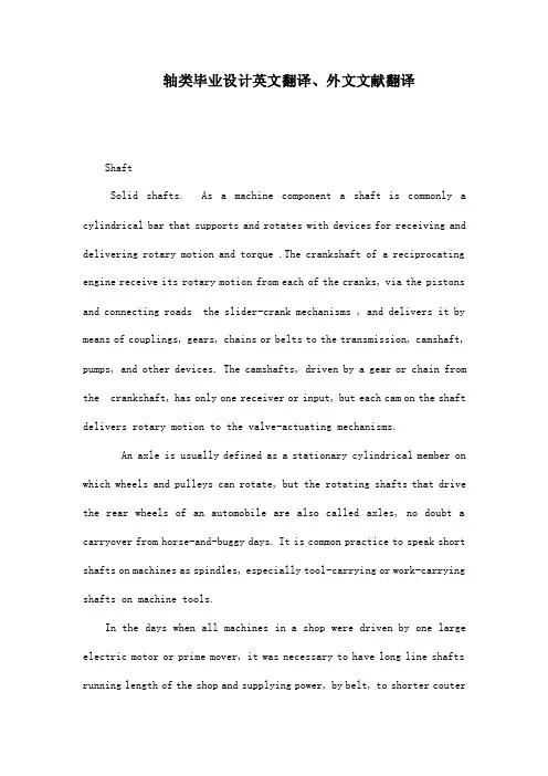
轴类毕业设计英文翻译、外文文献翻译ShaftSolid shafts. As a machine component a shaft is commonly a cylindrical bar that supports and rotates with devices for receiving and delivering rotary motion and torque .The crankshaft of a reciprocating engine receive its rotary motion from each of the cranks, via the pistons and connecting roads the slider-crank mechanisms , and delivers it by means of couplings, gears, chains or belts to the transmission, camshaft, pumps, and other devices. The camshafts, driven by a gear or chain from the crankshaft, has only one receiver or input, but each cam on the shaft delivers rotary motion to the valve-actuating mechanisms.An axle is usually defined as a stationary cylindrical member on which wheels and pulleys can rotate, but the rotating shafts that drive the rear wheels of an automobile are also called axles, no doubt a carryover from horse-and-buggy days. It is common practice to speak short shafts on machines as spindles, especially tool-carrying or work-carrying shafts on machine tools.In the days when all machines in a shop were driven by one large electric motor or prime mover, it was necessary to have long line shafts running length of the shop and supplying power, by belt, to shorter coutershafts, jack shafts, or head shafts. These lineshafts were assembled form separate lengths of shafting clampled together by rigid couplings. Although it is usually more convenient to drive each machine with a separate electric motor, and the present-day trend is in this direction, there are still some oil engine receives its rotary motion from each of the cranks, via the pistons and connecting roads the slider-crank mechanisms , and delivers it by means of couplings, gears, chains or belts to the transmission, camshaft, pumps, and other devices. The camshafts, driven by a gear or chain from the crankshaft, has only one receiver or input, but each cam on the shaft delivers rotary motion to the valve-actuating mechanisms.An axle is usually defined as a stationary cylindrical member on which wheels and pulleys can rotate, but the rotating shafts that drive the rear wheels of an automobile are also called axles, no doubt a carryover from horse-and-buggy days. It is common practice to speak short shafts on machines as spindles, especially tool-carrying or work-carrying shafts on machine tools.In the days when all machines in a shop were driven by one large electric motor or prime mover, it was necessary to have long line shafts running length of the shop and supplying power, by belt, to shorter coutershafts, jackshafts, or headshafts. These line shafts were assembled form separate lengths of shafting clampled together by rigid couplings.Although it is usually more convenient to drive each machine with a separate electric motor, and the present-day trend is in this direction, there are still some situation in which a group drive is more economical.A single-throw crankshaft that could be used in a single-cylinder reciprocating engine or pump is shown in Figure 21. The journals A andB rotate in the main bearings,C is the crankpin that fits in a bearing on the end of the connecting rod and moves on a circle of radius R about the main bearings, whileD andE are the cheeks or webs.The throw R is one half the stroks of the piston, which is connected, by the wrist pin, to the other end of the connecting rod and guided so as to move on a straight path passing throw the axis XX. On a multiple-cylinder engine the crankshaft has multiple throws---eight for a straight eight and for a V-8---arranged in a suitable angular relationship.Stress and strains. In operation, shafts are subjected to a shearing stress, whose magnitude depends on the torque and the dimensions of the cross section. This stress is a measure of resistance that the shaft material offers to the applied torque. All shafts that transmit a torque are subjected to torsional shearing stresses.In addition to the shearing stresses, twisted shafts are also subjected to shearing distortions. The distorted state is usually defined by the angle of tw。
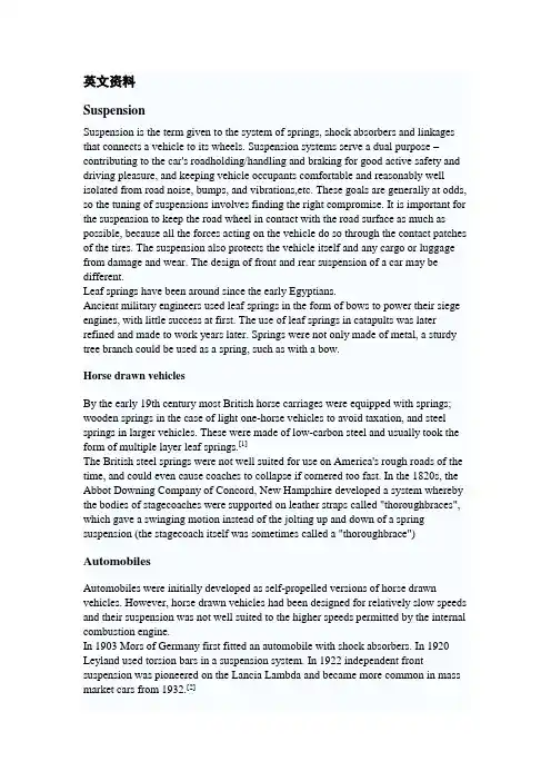
英文资料SuspensionSuspension is the term given to the system of springs, shock absorbers and linkages that connects a vehicle to its wheels. Suspension systems serve a dual purpose –contributing to the car's roadholding/handling and braking for good active safety and driving pleasure, and keeping vehicle occupants comfortable and reasonably well isolated from road noise, bumps, and vibrations,etc. These goals are generally at odds, so the tuning of suspensions involves finding the right compromise. It is important for the suspension to keep the road wheel in contact with the road surface as much as possible, because all the forces acting on the vehicle do so through the contact patches of the tires. The suspension also protects the vehicle itself and any cargo or luggage from damage and wear. The design of front and rear suspension of a car may be different.Leaf springs have been around since the early Egyptians.Ancient military engineers used leaf springs in the form of bows to power their siege engines, with little success at first. The use of leaf springs in catapults was later refined and made to work years later. Springs were not only made of metal, a sturdy tree branch could be used as a spring, such as with a bow.Horse drawn vehiclesBy the early 19th century most British horse carriages were equipped with springs; wooden springs in the case of light one-horse vehicles to avoid taxation, and steel springs in larger vehicles. These were made of low-carbon steel and usually took the form of multiple layer leaf springs.[1]The British steel springs were not well suited for use on America's rough roads of the time, and could even cause coaches to collapse if cornered too fast. In the 1820s, the Abbot Downing Company of Concord, New Hampshire developed a system whereby the bodies of stagecoaches were supported on leather straps called "thoroughbraces", which gave a swinging motion instead of the jolting up and down of a spring suspension (the stagecoach itself was sometimes called a "thoroughbrace")AutomobilesAutomobiles were initially developed as self-propelled versions of horse drawn vehicles. However, horse drawn vehicles had been designed for relatively slow speeds and their suspension was not well suited to the higher speeds permitted by the internal combustion engine.In 1903 Mors of Germany first fitted an automobile with shock absorbers. In 1920 Leyland used torsion bars in a suspension system. In 1922 independent front suspension was pioneered on the Lancia Lambda and became more common in mass market cars from 1932.[2]Important propertiesSpring rateThe spring rate (or suspension rate) is a component in setting the vehicle's ride height or its location in the suspension stroke. Vehicles which carry heavy loads will often have heavier springs to compensate for the additional weight that would otherwise collapse a vehicle to the bottom of its travel (stroke). Heavier springs are also used in performance applications where the loading conditions experienced are more extreme. Springs that are too hard or too soft cause the suspension to become ineffective because they fail to properly isolate the vehicle from the road. Vehicles that commonly experience suspension loads heavier than normal have heavy or hard springs with a spring rate close to the upper limit for that vehicle's weight. This allows the vehicle to perform properly under a heavy load when control is limited by the inertia of the load. Riding in an empty truck used for carrying loads can be uncomfortable for passengers because of its high spring rate relative to the weight of the vehicle. A race car would also be described as having heavy springs and would also be uncomfortably bumpy. However, even though we say they both have heavy springs, the actual spring rates for a 2000 lb race car and a 10,000 lb truck are very different. A luxury car, taxi, or passenger bus would be described as having soft springs. Vehicles with worn out or damaged springs ride lower to the ground which reduces the overall amount of compression available to the suspension and increases the amount of body lean. Performance vehicles can sometimes have spring rate requirements other than vehicle weight and load.Mathematics of the spring rateSpring rate is a ratio used to measure how resistant a spring is to being compressed or expanded during the spring's deflection. The magnitude of the spring force increases as deflection increases according to Hooke's Law. Briefly, this can be stated aswhereF is the force the spring exertsk is the spring rate of the spring.x is the displacement from equilibrium length i.e. the length at which the spring is neither compressed or stretched.Spring rate is confined to a narrow interval by the weight of the vehicle,load the vehicle will carry, and to a lesser extent by suspension geometry and performance desires.Spring rates typically have units of N/mm (or lbf/in). An example of a linear spring rate is 500 lbf/in. For every inch the spring is compressed, it exerts 500 lbf. Anon-linear spring rate is one for which the relation between the spring's compression and the force exerted cannot be fitted adequately to a linear model. For example, the first inch exerts 500 lbf force, the second inch exerts an additional 550 lbf (for a total of 1050 lbf), the third inch exerts another 600 lbf (for a total of 1650 lbf). In contrast a 500 lbf/in linear spring compressed to 3 inches will only exert 1500 lbf.The spring rate of a coil spring may be calculated by a simple algebraic equation or it may be measured in a spring testing machine. The spring constant k can be calculated as follows:where d is the wire diameter, G is the spring's shear modulus (e.g., about 12,000,000 lbf/in² or 80 GPa for steel), and N is the number of wraps and D is the diameter of the coil.Wheel rateWheel rate is the effective spring rate when measured at the wheel. This is as opposed to simply measuring the spring rate alone.Wheel rate is usually equal to or considerably less than the spring rate. Commonly, springs are mounted on control arms, swing arms or some other pivoting suspension member. Consider the example above where the spring rate was calculated to be500 lbs/inch, if you were to move the wheel 1 inch (without moving the car), the spring more than likely compresses a smaller amount. Lets assume the spring moved 0.75 inches, the lever arm ratio would be 0.75 to 1. The wheel rate is calculated by taking the square of the ratio (0.5625) times the spring rate. Squaring the ratio is because the ratio has two effects on the wheel rate. The ratio applies to both the force and distance traveled.Wheel rate on independent suspension is fairly straight-forward. However, special consideration must be taken with some non-independent suspension designs. Take the case of the straight axle. When viewed from the front or rear, the wheel rate can be measured by the means above. Yet because the wheels are not independent, when viewed from the side under acceleration or braking the pivot point is at infinity (because both wheels have moved) and the spring is directly inline with the wheel contact patch. The result is often that the effective wheel rate under cornering is different from what it is under acceleration and braking. This variation in wheel rate may be minimized by locating the spring as close to the wheel as possible.Roll couple percentageRoll couple percentage is the effective wheel rates, in roll, of each axle of the vehicle just as a ratio of the vehicle's total roll rate. Roll Couple Percentage is critical in accurately balancing the handling of a vehicle. It is commonly adjusted through the use of anti-roll bars, but can also be changed through the use of different springs.A vehicle with a roll couple percentage of 70% will transfer 70% of its sprung weight transfer at the front of the vehicle during cornering. This is also commonly known as "Total Lateral Load Transfer Distribution" or "TLLTD".Weight transferWeight transfer during cornering, acceleration or braking is usually calculated per individual wheel and compared with the static weights for the same wheels.The total amount of weight transfer is only affected by 4 factors: the distance between wheel centers (wheelbase in the case of braking, or track width in the case of cornering) the height of the center of gravity, the mass of the vehicle, and the amount of acceleration experienced.The speed at which weight transfer occurs as well as through which components it transfers is complex and is determined by many factors including but not limited to roll center height, spring and damper rates, anti-roll bar stiffness and the kinematic design of the suspension links.Unsprung weight transferUnsprung weight transfer is calculated based on the weight of the vehicle's components that are not supported by the springs. This includes tires, wheels, brakes, spindles, half the control arm's weight and other components. These components are then (for calculation purposes) assumed to be connected to a vehicle with zero sprung weight. They are then put through the same dynamic loads. The weight transfer for cornering in the front would be equal to the total unsprung front weight times theG-Force times the front unsprung center of gravity height divided by the front track width. The same is true for the rear.Suspension typeDependent suspensions include:∙Satchell link∙Panhard rod∙Watt's linkage∙WOBLink∙Mumford linkage∙Live axle∙Twist beam∙Beam axle∙leaf springs used for location (transverse or longitudinal)The variety of independent systems is greater and includes:∙Swing axle∙Sliding pillar∙MacPherson strut/Chapman strut∙Upper and lower A-arm (double wishbone)∙multi-link suspension∙semi-trailing arm suspension∙swinging arm∙leaf springsArmoured fighting vehicle suspensionMilitary AFVs, including tanks, have specialized suspension requirements. They can weigh more than seventy tons and are required to move at high speed over very rough ground. Their suspension components must be protected from land mines and antitank weapons. Tracked AFVs can have as many as nine road wheels on each side. Many wheeled AFVs have six or eight wheels, to help them ride over rough and soft ground. The earliest tanks of the Great War had fixed suspensions—with no movement whatsoever. This unsatisfactory situation was improved with leaf spring suspensions adopted from agricultural machinery, but even these had very limited travel. Speeds increased due to more powerful engines, and the quality of ride had to be improved. In the 1930s, the Christie suspension was developed, which allowed the use of coil springs inside a vehicle's armoured hull, by redirecting the direction of travel using a bell crank. Horstmann suspension was a variation which used a combination of bell crank and exterior coil springs, in use from the 1930s to the 1990s.By the Second World War the other common type was torsion-bar suspension, getting spring force from twisting bars inside the hull—this had less travel than the Christie type, but was significantly more compact, allowing the installation of larger turret rings and heavier main armament. The torsion-bar suspension, sometimes including shock absorbers, has been the dominant heavy armored vehicle suspension since the Second World War.中文翻译悬吊系统(亦称悬挂系统或悬载系统)是描述一种由弹簧、减震筒和连杆所构成的车用系统,用于连接车辆与其车轮。

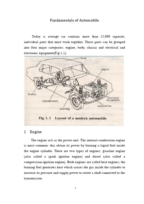
Fundamentals of AutomobileToday is average car contains more than 15,000 separate, individual parts that must work together. These parts can be grouped into four major categories: engine, body, chassis and electrical and electronic equipment(Fig.1.1).1 EngineThe engine acts as the power unit. The internal combustion engine is most common: this obtain its power by burning a liquid fuel inside the engine cylinder. There are two types of engines: gasoline engine (also called a spark ignition engine) and diesel (also called a compression-ignition engine). Both engines are called heat engines; the burning fuel generates heat which causes the gas inside the cylinder to increase its pressure and supply power to rotate a shaft connected to the transmission.2 BodyAn automobile body is a sheet metal shell with windows, doors, a hood, and a trunk deck built into it. It provides a protective covering for the engine, passengers, and cargo. The body is designed to keep passengers safe and comfortable. The body styling provides an attractive, colorful, modern appearance for the vehicle.3 chassisThe chassis is an assembly of those systems that are the major operating parts of a vehicle. The Chassis includes the transmission, suspension, steering, and brake system.3.1 TransmissionThe transmission system comprises clutch, gearbox, propeller shaft, rear axle and differential and the driven road wheels.ClutchThe clutch or torque converter has the task of disconnecting and connecting the engine's power from and to the driving wheels of the vehicle. This action may be manual or automatic.GearboxThe main purpose of the gearbox is to provide a selection of gear ratios between the engine and driving wheels, so that the vehicle can operate satisfactorily under all driving conditions. Gear selection may be done manually by the driver or automatically by a hydraulic control system.Propellor shaftThe function of the propeller (drive) shaft is to transmit the drivefrom the gearbox to the input shaft of the rear axle and differential assembly. Flexible joints allow the rear axle and wheels to move up and down without affecting operation.The role of the drive shaft from the transmission the driving force transmitted to the rear axle input shaft and the differential assembly. Universal joint allows the rear axle and wheels move up and down without affecting operation.Rear axle and differentialThe rear axle and differential unit transmits the engine's rotational power through 90 from propshaft to axle shaft to axle shaft to road wheels. A further function is to allow each driven wheel to turn at a different speed; essential when cornering because the outer wheel must turn further than the inside wheel. A third function is to introduce another gear ratio for torque multiplication.3.2 SuspensionThe axles and wheels are isolated from the chassis by a suspension system . The basic job of the suspension system is to absorb the shocks caused by irregular road surfaces that would otherwise be transmitted to the vehicle and its occupants, thus helping to keep the vehicle on a controlled and level course, regardless of road conditions.3.3 SteeringThe steering system, under the control of the driver at the steering wheel, provides the means by which the front wheels are directionally turned. The steering system may be power assisted to reduce the effort required to turn the steering wheel and make the vehicle easier to manoeuvre.3.4 BrakesThe braking system on a vehicle has three main functions. It must be able to reduce the speed of the vehicle, when necessary; it must be able to stop the car in as short a distance as possible; it must be able to hold the vehicle stationary. The braking action is achieved as a result of the friction developed by forcing a stationary surface(the brake lining)into contact with a rotating surface(the drum or disc).Each wheel has a brake assembly of either the drum type or the disc type, hydraulically operated when the driver applies the foot brake pedal.4 Electrical Equipment and InstrumentationThe electrical system supplies electricity for the ignition, horn, lights, heater, and starter. The electricity level is maintained by a charging circuit. This circuit consists of a battery, and an alternator (or generator). The battery stores electricity. The alternator changes the engine's mechanical energy into electrical energy and recharges the battery.The motor vehicle incorporates a number of electrical devices that are used for:Battery charging –alternator and regulator.Engine purposes –starting and ignition.Safety and convenience –lighting, horn, wipers, washers etc.Driver information –instrumentation and warning lamps.Of these devices instrumentation is, perhaps, most influenced by the advance of microelectronics. The basic electromechanical systems of:Speedometer –for indicating vehicle speed.Engine oil pressure –warning lamp or gauge to show operating limits.Engine coolant temperature –warning lamp or gauge to show operating limits.Battery charging –warning lamp or gauge to indicate satisfactory/unsatisfactory action.Fuel tank content –gauge to show amount of fuel in the fuel tank.are giving way to computerized vehicle management information centres.The Steering System1 The Steering GearThe steering gear mechanism enables the driver to turn the front wheels of the car. The mechanism consists of a steering gear box, pitman arm, drag link, tie rods, steering arms, and steering knuckles, the latter supporting the front wheels(Fig.6.1).Turning the steering wheel turns the steering shaft to which a worm gear is attached within the steering gear box. The steering worm moves a roller through a part of an arc, the motion of which is transmitted to the pitman arm, which moves back and forth across the width of the frame. Several arrangements of rods and levers are in common use but, in general, a drag link, connected to the pitmen arm, transmits the movement to tie rods which are connected to the steering arms. Sideward movement of the steering arms turns the steering knuckles, and the wheels, as they are pivoted on front end support mechanism.There are two types of steering system: manual steering system and power steering system. In the manual type, the driver does all the work of turning the steering wheel, steering gears, wheels, and tires. In the power type, hydraulic fluid assists the operation so that the driver's effort is reduced.Mechanical steering system: And changes the transmission systemby the diverter to be composed.Diverter: By the steering wheel, the steering wheel steering axle, changes meshing to pay (diverter) to be composed.Steering transmission system: By drop arm (drop arm), drag link, drag link arm, about trapezoidal arm, steering knuckle tie rod, if a dry bulb joint composes.Power steering system: Changes the augmenter constitution by mechanical steering system Canada.A typical power steering system needs a power steering pump and reservoir in addition to the steering gear(Fig.6.2). These parts store the hydraulic fluid and provide the hydraulic pressure to assist steering. In most instances, a V-belt from the engine power the hydraulic pump. Hoses lead from the pump to the steering gear and back to the pump.In steering gear box the gear is slightly larger and has other parts. The wormshaft is the same in both systems. Instead of a ball nut, though, the power steering system uses a power piston or rack piston in steering gear box. The power piston has teeth on one side that meshwith the sector teeth. The forward and backward motion of the power piston moves the sector, pitman shaft, and steering linkage.The power steering gear also uses a control valve to send hydraulic fluid into the steering gear at the right time. When the steering wheel starts to move in either direction, the valve opens its ports to sent fluid under pressure into the main chamber of the steering gear. The fluid pushes against the power piston and assists the motion of the steering wheel.Fig.6.2 In an integral power steering system, the power and control are in the same housing as the steering gear2 Front-GeometryThe front wheels are arranged at various angles to the car frame to provide good steering control and stability. The angles are discussed in the following order: caster, camber, steering axis inclination, toe, and turning radius.Caster is the slant of the kingpin forward at the bottom(Fig.6.3). (NOTE: Modern passenger car does not use a kingpin in an independently mounted front wheel suspension, but reference to its former position helps to clarify some front end concepts. The positionof the kingpin would be on a direct line drawn between the two ball joints). The front wheels, when provided with the proper amount of caster, will align themselves in the direction in which the car is moving. Too much caster will cause hard steering and shimmy at low speed. Too little caster will cause wander or weave at high speed and erratic steering when applying the brakes.Camber is the angle between a vertical line and a line drawn through the center of the wheel(Fig.6.4). The top of the wheel is inclined away from the car. The purpose of camber is to place the center of the tire directly under the extended line of the kingpin for easier steering. This places the weight of the car directly over the pivot point.Steering Axis Inclination is the outward tilt of the bottom of the kingpin toward the wheel(Fig.6.5). Modern engineering practice is to minimize camber in order to reduce uneven tire wear, and increase theFig.6.3 Caster Fig.6.4 Camber angular inclination of the kingpin to place its centerline directly under the center of the tire for ease in steering.Steering axis inclination also provides steering stability by raisingthe entire front end of the vehicle during a turn. Gravity causes the spindle ends to tend to return to their straight ahead position. This force is not enough to cause steering, but is enough to provide excellent directional stability. Steering axis inclination is probably a more important steering stability factor than caster.Toe-in is the difference in distance between the front and rear of the front tires, measured at spindle height(Fig.6.6). That is, the wheels are aimed slightly in as if to cross each other, it seems to cross each other's path. Due to compression of the steering linkage parts, the front wheels tend to turn out or away from each other. To offset this, they are provided with a small amount of toe-in. In operation, the wheels travel parallel paths and no side scuffing occurs.Fig.6.5 Steering axis inclinationTurning Radius, or toe-out on turns, is needed when turning a corner. Because the outside wheel on a curve turn about a longer arcthan does the inside wheel, it is necessary to have the inside wheel turn at a sharper angle to prevent tire scuffing and wear. To obtain this action, the steering arms are set at an angle to the wheels. Although the tie rod moves each arm an equal distance, the angular movement is unequal and the wheels toe-out. The sharper the turning angle, the more toe-out results.Fig.6.6 Toe-in汽车部件目前大多数的汽车由超过15000个各自独立的零部件组成,这些零部件必须一起配合工作。
附录A 外文文献Electric Power Steering system1.HistoryIn automobile development course, Steering system experienced four stages of development: from the initial mechanical Steering system (for your DNS setting Steering, abbreviation ) development for Hydraulic Steering system (Hydraulic Power Steering, abbreviation HPS), then again appeared electronically controlled Hydraulic Steering system (Electro Hydraulic Power Steering, abbreviation EHPS) and Electric Power Steering system (Steering, room Power as EPS). Assemble mechanical steering system of car parking and low-speed driving, when the driver's steering control burden too heavy, in order to solve this problem, the American GM in the 1950s took the lead in the car hydraulic steering system. But, hydraulic steering system can't juggle vehicles to speed portability and high speed, so the steering stability Koyo in Japan in 1983, with the company introduced the application of speed sensing function of hydraulic steering system. This new type of steering system can provide speed increased with the decreasing steering, but complicated structure, cost is higher,and cannot overcome hydraulic system itself has many shortcomings, is a cross between a hydraulic steering and electric power steering the transition between the products. In 1988, Japan Suzuki company first in small cars equipped with Cervo Koyo company development on the steering column, power type electric power steering system; In 1990, Japan Honda NSX in sports car company adopted self-developed rack power type electric power steering system, henceforth unveils the electric power steering in cars applications history2.Working principleElectric power steering system are as follows: first, the working principle, torque sensor measured on steering wheel drivers on the manipulation of the moment, the wheel speed sensors detect the vehicle driving speed, then present the two signals to ECU; According to the built-in control strategy: ECU, calculates the ideal target booster torque, into current instructions to motor; Then, the power generated by the torque motor slowdown institutions amplification on steering system in mechanical manipulation of the moment, and the driver together to overcome resistance torque, realize to the vehicle steering.3. Working processElectric power steering system as traditional hydraulic system alternative products has entered into the auto manufacturing. And had predicted instead, EPS not only applicable to small cars, and some for 12V medium vehicle installed electric system.EPS system includes the following components:The torque sensor: detection steering wheel motion and vehicle motion situation;Electronic control units: according to provide the torque sensor the size of the signal computing power;Motor: according to the electronic control units; turn power output value generationReduction gear: improve motor power, and produce turn it sends to steering mechanism.Other vehicle system control algorithm input information is provided by the car CAN bus (for example steering Angle and bus speed, etc.). Motor drive also need other information, such as motor rotor position and the three-phase motor sensor (current sensor provided). Motor control by four MOSFET, due to micro controller cannot direct drive of large gate capacitance, MOSFET using drive IC form needed the interface, for safety, complete motor control system must implement monitoring,motor control system integration in PCB, usually contains a relay, the relay use, as the main switch under the condition of the fault detection, disconnect motor and electronic control units.Micro control device must control EPS system and have brushless motor. Micro control device according to the torque sensor provide needed the steering wheel torque information, forming a current control loop. In order to improve the security of the system level, the micro control device should have an on-board oscillator, so even in external oscillator malfunction case, also ensure micro control device performance, also should have chip watchdog. Infineon XC886 integration of the company all the important micro control device component, other safety features for through the software to realize, if must implement safety standards IEC61508 industries, you have to finish all kinds of diagnosis and self-inspection task and increase micro control device work load. At present different customers use of torque sensor and rotor position sensor difference is very big. They use different measuring principle, such as decomposing machine, magnetic resonance device, based on the integration of giant magnet or stance sensor.The role of power levels is switch electric current. The power level has two main functions: drive IC control andprotection MOSFET, MOSFET itself and to be responsible for switch currents. MOSFET and partition.Micro control device PWM output port provides driver current and voltage is too low, can't directly connected with MOSFET screen realization. Drive IC role is to provide enough current, the grid to charge for MOSFET, so that in the and discharge 20kHz conditions, and ensure the normal realization switch for discretion side provides the high bar source voltage MOSFET, ensure that you get the low conduction resistance. If the high side MOSFET in open state, to source potential close battery level. Want to make MOSFET arrived at nominal conduction resistance, gate to higher than 8V source voltage. MOSFET completely conduction needed the most ideal voltage is required, therefore 10V or above a grid of potential than battery voltage 10V is higher. Charge pump is to ensure that the function to the largest extent reduce MOSFET power (even if low battery voltage conditions) circuit.The other key charge pump design according to different characteristics that can be PWM pattern request, achieve extremely low (low to 1%) and high rate of 390v (high to 100%). Drive IC another important function is testing, avoid damage toshort-circuit mosfets, affected MOSFET will be closed, diagnosis submitted to micro control device.附录B 外文文献的中文翻译电动助力转向系统1.发展历史在汽车的发展历程中,转向系统经历了四个发展阶段:从最初的机械式转向系统(Manual Steering,简称MS)发展为液压助力转向系统(Hydraulic Power Steering,简称HPS),然后又出现了电控液压助力转向系统(Electro Hydraulic Power Steering,简称EHPS)和电动助力转向系统(Electric Power Steering,简称EPS)。
Conventional Machining ProcessesConventional machining is the group of machining operations that use single- or multi-point tools to remove material in the form of chips. Metal cutting involves removing metal through machining operations. Machining traditionally takes place on lathes, drill presses, and milling machines with the use of various cutting tools. Most machining has very low set-up cost compared with forming, molding, and casting processes. However, machining is much more expensive for high volumes. Machining is necessary where tight tolerances on dimensions and finishes are required.Turning is one of the most common of metal cutting operations. In turning, a workpiece is rotated about its axis as single-point cutting tools are fed into it, shearing away excess material and creating the desired cylindrical surface. Turning can occur on both external and internal surfaces to produce an axially-symmetrical contoured part. Parts ranging from pocket watch components to large diameter marine propeller shafts can be turned on a lathe.Apart from turning, several other operations can also be performed on lathe.Boring and internal turning. Boring and internal turning are performed on the internal surfaces by a boring bar or suitable internal cutting tools. If the initial workpiece is solid, a drilling operation must be performed first. The drilling tool is held in the tailstock, and the latter is then fed against the workpiece. When boring is done in a lathe, the work usually is held in a chuck or on a face plate. Holes may be bored straight, tapered, or to irregular contours. Boring is essentially internal turning while feeding the tool parallel to the rotation axis of the workpiece.Facing is the producing of a flat surface as the result of a tool’s being fed across the end of the rotating workpiece. Unless the work is held on a mandrel, if both ends of the work are to be faced, it must be turned around after the first end is completed and then the facing operation repeated. The cutting speed should be determined from the largest diameter of the surface to be faced.Facing may be done either from the outside inward or from the center outward. In either case, the point of the tool must be set exactly at the height of center of rotation.Because the cutting force tends to push the tool away from the work, it is usually desirable to clamp the carriage to the lathe bed during each facing cut to prevent it from moving slightly and thus producing a surface that is not flat. In the facing of casting or other materials that have a hard surface, the depth of the first cut should be sufficient to penetrate the hard material to avoid excessive tool wear.Parting is the operation by which one section of a workpiece is severed from the remainder by means of cutoff tool. Because cutting tools are quite thin and must have considerable overhang, this process is less accurate and more difficult. The tool should be set exactly at the height of axis of rotation, be kept sharp, have proper clearance angles, and be fed into the workpiece at a proper and uniform feed rate.Threading can be considered as turning since the path to be travelled by the cutting tool is helical. However, there are some major differences between turning and threading. While in turning, the interest is in generating a smooth cylindrical surface, in threading the interest is in cutting a helical thread of a given form and depth which can be calculated from the formulae. There are two basic requirements for thread cutting. An accurately shaped and properly mounted tool is needed because thread cutting is a form-cutting operation. The resulting thread profile is determined by the shape of the tool and its position relative to the workpiece.The second by requirement is that the tool must move longitudinally in a specific relationship to the rotation of workpiece, because this determines the lead of the thread. This requirement is met through the use of the lead screw and the split unit, which provide positive motion of carriage relative to the rotation of spindleLathe bed is foundation of the engine lathe, which heavy, rugged casting is made to support the working parts of the lathe. The size and mass of the bed gives the rigidity necessary for accurate engineering tolerances required in manufacturing. On top of the bed are machined slideways that guide and align the carriage and tailstock, as they are move from one end of the lathe to the other.Headstock is clamped atop the bed at left-hand end of the lathe and contains the motor that drives the spindle whose axis is parallel to the guideways through a series of gears housed within the gearbox. The function of gearbox is to generate a number of different spindle speeds. A spindle gear is mounted on the rear of the spindle to transmit power through the change gears to the feeding box that distributes the power to the lead screw for threading or to the feed rod for turning.The spindle has a through hole extending lengthwise through which bar stocks can be fed if continuous production is used. The hole can hold a plain lathe center by its tapered inner surface and mount a chuck, a face plate or collet by its threaded outer surface.Carriage assembly is actually an H-shaped block that sits across the guideways and in front of lathe bed. The function of the carriage is to carry and move the cuttingtool longitudinally. It can be moved by hand or by power and can be clamped into position with a locking nut. The carriage is composed of the cross slide, compound rest, tool saddle, and apron.The cross slide is mounted on the dovetail guideways on the top of the saddle and it moved back and forth at 90°to the axis of the lathe by the cross slide lead screw. The lead screw can be hand or power activated.The compound rest is mounted on the cross slide and can be swiveled and clamped at any angle in a horizontal plane. The compound is typically used for cutting chamfers or tapers, but must also be used when cutting thread. The compound rest can only be fed by hand. There is no power to compound rest. The cutting tool and tool holder are secured in the tool post which is mounted directly to the compound rest.The tool saddle is an H shaped casting mounted on the top of the guideways and houses the cross slide and compound rest. It makes possible longitudinal, cross and angular feeding of the tool bit.The apron is attached to the front of the carriage and contains the gears and feed clutches which transmit motion from the feed rod or lead screw to carriage and cross slide. When cutting screw threads, power is provided to the gearbox of the apron by the lead screw. In all other turning operations, it is the feed rod that drives the carriage.Tailstock is composed of a low base and the movable part of the tail-stock proper, the transverse adjustments being made with a cross screw furnished with a square head. The two parts are hold together by the holding-down bolts which secure the tailstock to the bed.。
外文资料及翻译Steering system(1)To change the control mechanism basically mainly by the steering wheel, the steering axle, the steering tube column and so on to be composed.(2) Diverter becomes steering wheel's rotation steering arm's swinging or the rack axis straight reciprocating motion, and to changes the control force to carry on the enlargement the organization. The diverter fixes generally on the automobile frame or the automobile body, changes the control force after the diverter generally will also change the transmission direction.(3) Steering transmission system the strength which and the movement outputs the diverter passes to the wheel (knuckle), about and causes the wheel to carry on the deflection according to certain relations the organization.TypeCrooked to energy difference, the steering system may divide into the machinery steering system and the power steering system two broad headings crooked.Mechanical steering system: And changes the transmission system by the diverter to be composed.Diverter: By the steering wheel, the steering wheel steering axle, changes meshing to pay (diverter) to be composed.Steering transmission system: By drop arm (drop arm), drag link, drag link arm, about trapezoidal arm, steering knuckle tie rod, if a dry bulb joint composes.Power steering system: Changes the augmenter constitution by mechanical steering system Canada.1.Mechanical steering system The mechanical steering system changes the energy by pilot's physical strength achievement, all power transmission are the machinery. The mechanical steering system by changes the control mechanism, the diverter and changes the transmission system three major part to be composed.(1) steering control mechanismChanges the control mechanism by the steering wheel, the steering axle, the steering tube column and so on to be composed, its function is rotates the pilot steering wheel's control force to pass to the divertor.(2) DivertorThe diverter (also often is called steering unit) is completes from the rotary motion to the translation (or approximate straightline motion) a group of gear mechanism, simultaneously is also in the steering system speed reducer drive. At present the commonly used toothed wheel rack type, follows round the world the crank to refer to sells the type, the worm bearing adjuster crank to refer to sells the type, to follow round the world - the tooth rack tooth fan type, the worm bearing adjuster hoop type and so on. We mainly introduce the first several kinds.1) Gear rack type divertorThe gear rack type diverter divides the both sides output type and among (or single end) the output type two kinds .The both sides output's gear rack type diverter, changes the gear shaft as the transmission vice-host moving parts and installs through the bearing in the diverter shell, its upper extreme through spline and universal joint sliding yoke and steering axle connection. With the steering gear meshing steering rack level arrangement, the both sides with change the steering knuckle tie rod through a ball place to be connected. The spring presses through the briquetting the rack depending in the gear, guarantees ceaseless meshing.Spring's pretightening up force available adjustment thread plug adjustment. When rotates the steering wheel, the diverter gear-driven, causes with it meshing rack along the end motion, thus about causes the steering knuckle tie rod to lead about the knuckle to rotate, causes to change the wheel deflection, thus realizes motor turning.Middle output gear rack type diverter, its structure and principle of work and both sides output gear rack type diverter basic same, the difference lies in it to change the steering knuckle tie rod in steering rack's middle with the bolt with about to be connected. On single-ended output's gear rack type diverter, a rack's end with changes the steering knuckle tie rod through the inside and outside bracket to be connected.2) Follows round the world-like the divertorFollows round the world-like the diverter is one of present domestic and foreign application most widespread structure patterns, generally has two-stage drive, the first level is screw rod nut transmission, the second level is tooth rack tooth fan transmission.In order to reduce between the steering screw steering nut's friction, the two's thread immediate contact, during is loaded with many steel balls, realizes the rolling friction. On the steering screw and the nut processes the profiled outline is two section or three section of not concentric circular arc composition approximate semicircle spiral groove. The two's spiral groove can coordinate to form the approximate circular cross section the spiral tubular channel.The nut side has two pair of through holes, may henceforth the vent plug enter the steel ball in the helix channel. Outside the steering nut has two steel ball drive pipes, each drive pipe's both sides insert the nut side separately in a pair of through hole. In the drive pipe has also packed the steel ball. Thus, in two drive pipes and nut's spiral tubular channels combine two respectively independent seals the steel ball " the flow channel ".When the steering screw rotates, passes to the steering nut through the steel ball the strength, the nut namely along the end motion. At the same time, friction couple function between the screw rod and the nut and under the steel ball, all steel balls then rolls in the spiral tubular channel, formation " ball class ". When the diverter works, two rows steel balls are only in the respective seal flow channel internal recycling, will leave.3) The worm bearing adjuster crank refers to sells the type diverterThe worm bearing adjuster crank refers to sells the type diverter's transmissionvice-(by the steering worm primarily moving parts, it is installs from themoving parts in the rocker arm shaft crank nose refers to sells. When the steering worm rotates, refers to with it meshing sells namely circles the rocker arm shaft spool thread along the circular, and leads the rocker arm shaft rotation.(3) Steering transmission systemSteering transmission system the function is the strength which and the movement outputs the diverter passes to the steering axle both sides the knuckle, causes the both sides wheering wheel deflection, and causes two wheering wheel deflection angles according to certain relational change, guarantees when motor turning the wheel and the ground relative sliding is as far as possible small.1)Uses for parts with the non-independent suspension fork changes the transmission system mainly to include the steering arm, to change the drag link, the steering, and the steering trapezium. In the front axle is only in the steering axle situation, by changes the steering trapezium general arrangement which the steering knuckle tie rod and the left and right trapezoidal arm are composed after the front axle, when the wheering wheel is in with the automobile straight line travel corresponding neutral point, trapezoidal arm and steering knuckle tie rod in and path parallel plane (horizontal plane) in angle of intersection >90.In the engine position is low or in the steering axle concurrently sufficient driving axle's situation, to avoid the movement interference, often steering trapezium arrangement before the front axle, this time above angle of intersection <90, if the steering arm is not around swings in the automobile fore-and-aft plane, but is shaking right toward left with the path parallel plane, then may change the drag link horizontal, and sells taking advantage of ball leads directly changes the steering knuckle tie rod, thus pushes somebody into doing something the both sides trapezoidal arm rotation.2)Uses for parts with the independent suspension fork changes the transmission systemWhen wheering wheel independent suspension, each wheering wheel needs to be opposite in the frame makes the independence movement, thus the steering axle must be the separation type. With this corresponding, changes in the transmission system the steering trapezium also to be the separation type.,As shown in Figure 9 b. If Pitman is not in the vehicle longitudinal plane backwards and forwards, but is in the plane parallel to the road to shake, you can bring the steering linkage 3 exhaust, and ball head pin directly driven steering tie rod 6, thus pushing the sides of a trapezoid arm. 2) and independent suspension with the steering linkage when steering wheel independent suspension, each steering wheel needs relative to the frame for independence movement, thereby steering bridge must be disconnected. And accordingly, steering linkage of steering or must be disconnected.The role of steering lever is passed from the Pitman force and motion to steering arm (or steering). It force existing tension and pressure, so direct lever is is the use of high-quality special steel manufacturing, in order to ensurereliable operation. Linkage of typical structure as shown in Figure 11. In the steering wheel to deflect or elastic deformation due to the suspension and relative to the frame beats, steering lever and Pitman and steering relative movements are spatial movement, in order not to occur, the interference of the three connections takes the ball PIN. 4) Steering damper as speed increases, the modern automobile steering wheel sometimes generate shimmy (steering wheel around the kingpin axis reciprocating swing, even whole body vibration), which not only affect vehicle stability, but also affected comfort, aggravate the nose wheel wear and tear. In the steering linkage in setting steering damper is to overcome the steering wheel shimmy of effective measures. Steering damper side of the body (or front axle) articulated, the other end and steering lever (or articulated steering).Use mechanical steering can implement steering, when steering axle load larger that the pilot's manual as steering energy is difficult to turn smoothly. Power steering system is in mechanical steering system on the basis of a set of steering device. Steering device reduces driver operated steering wheel. Steering energy from the driver's physical strength and motor (or motors), engine (or motors) accounted for the major part, through the steering device. Normally, pilots can easily control the steering. But in the steering device failure, I went back to mechanical steering system state, in general but also by the driver's steering tasks independently. (1) hydraulic power steering systems-which belongs to the steering device part is: steering pump 7, steering tubing 8, steering, and is located in the integral oil tank 6 EPS 4 internal steering control valve and steering power cylinder 5, etc. When the pilot turned the steering wheel 1 by mechanical steering makes steering tie rod 9 mobile, and driven steering, the steering wheel deflection, thus changing the car driving direction. At the same time, the steering shaft also driven steering internal rotation of the steering control valve, the hydraulic steering power cylinder produces helps the driver's steering forces. Because of the role of the steering device, the driver simply than mechanical steering system is much smaller, steering torque of the steering wheel deflection. Advantages and disadvantages: high energy consumption, especially when slow turning, think the comparison engine driving direction also relatively easy. And because the hydraulic pump pressure, is also easier to damage to the power system.(2) electric power steering system, referred to as EPS or EPS (electric, Electronic Power Steering system) in mechanical steering mechanism, increase signal sensor, electronic control unit and the Steering Body. EPS is the use of electric motor as a power source, depending on the speed of help and steering parameters, and other factors, by the electronic control unit to complete the power-assisted control, its principles can be summarized as follows: when handling and steering wheel, mounted on the steering wheel shaft torque sensor constantly measured steering shaft torque signal, the signal and the vehicle speed signal input to the electronic control unit. The electronic control unit according to the input signal, determine power torque in magnitude and direction, which is the selected motor currents and rotation direction, adjusting the size of the auxiliary power steering. Motor torque by electromagnetic clutch by gear reducer by moments later, the car's steering mechanism, to achieve a vehicle condition of steering forces. For example, Fox's EHPAS e hydraulic system from a computer according to engine speed and vehicle speed and steering angle and other signal, drive e pump to deliver power steering system. Power feel very natural. So many people on Fox in the direction of the feeling is quite good, feeling of steering control can be as long as you want. Some vehicles also claims the use of electronic power, but just motor power, no hydraulic aided, prone to noise. Power effects are far behind Fox this type of electronic power.转向系统汽车转向系统:汽车上用来改变或恢复其行驶方向的专设机构称为汽车转向系统。
铁路货车转向架设计英文回答:Railway Bogie Design.The bogie is a crucial component of a railway vehicle, connecting the vehicle body to the wheels and enabling it to negotiate curves and uneven track conditions. The design of a bogie involves several key considerations:Wheel Arrangement: The arrangement of wheels within the bogie, such as a two-axle or three-axle design, determines the vehicle's stability and load distribution.Suspension System: The suspension system, which includes springs, dampers, and linkages, absorbs vertical and lateral forces, ensuring stability and ride comfort.Traction and Braking Systems: The bogie houses the traction motors and braking systems, enabling the vehicleto accelerate, decelerate, and maintain speed.Frame Design: The bogie frame, typically made of steel or composite materials, provides the structural support for the various components and ensures durability.Weight Distribution: The weight of the bogie and its components is optimized to balance the vehicle's load, ensuring stability and minimizing wear and tear on the track.Types of Bogies.There are numerous types of bogies used in railway vehicles, each tailored to specific applications:Conventional Bogie: A traditional design with two axles and a central pivot pin, widely used in freight and passenger cars.Articulated Bogie: Features two interconnected bogie frames, providing increased stability and reduced wheelwear in curves.Jacob's Bogie: A specialized type with a shared center pivot between two adjacent carriages, designed for high-speed trains.Bolsterless Bogie: A modern design that eliminates the bolster and employs a direct connection between the frame and axle boxes, reducing weight and improving ride quality.Design Considerations.When designing a bogie, engineers must consider factors such as:Vehicle Type: The intended application, whether for freight or passenger transport, influences the bogie's design requirements.Speed and Capacity: The operating speed and load capacity determine the bogie's stability, suspension, and traction systems.Track Conditions: The track geometry and quality dictate the bogie's suspension and frame design to withstand various track conditions.Environmental Factors: Temperature, humidity, and corrosive environments must be accounted for in the design to ensure durability and reliability.中文回答:铁路转向架设计。
基于确保疲劳强度和减轻重量的转向架构架设计B.H.Park and K.Y.Lee机械工程学院,延世大学,首尔,韩国.这份手稿是于2005年4月8日收到后接受修改,出版于2005年11月25日。
DOI: 10.1243/09544097F01405摘要:在一个转向架的设计发展过程中,转向架构架疲劳强度的影响是一个重要的设计准则。
此外,为了节约能源和材料需要减轻重量。
在这项研究中,用有限元方法在各种加载条件下对转向架构架进行疲劳分析是根据UIC的标准形成的,这种方法试图通过人工神经网络和遗传算法来减小转向架构架的重量。
关键词:转向架、强度、疲劳强度分析、神经网络、优化。
1简介:转向架是列车上一个非常重要的构件,它承载着铁道车辆在运动中的各种力。
铁道车辆的运动受到轨道的几何形状、轮轨相互作用、悬挂装置和零部件的惯性力的影响。
同时,一台高速运行列车的转向架结构的重量应该尽可能轻。
因此,转向架的强度应该在国际标准如UIC[1]和JIS [2]的基础上仔细地进行计算分析,以获得一个合理的设计方案。
在过去的设计过程里,诸如一些试验,现场测试,并对原型改进得到一个合理的设计等步骤需要许多时间和很高的成本。
然而,在计算机辅助工程(CAE)产品设计中,应用有限元分析方法(FE)可以减少所需的成本和时间。
利用有限元分析方法研究转向架构架曾有几次先例[3,4]。
此外,转向架占车辆总重量的一大部分。
目前设计者在节省能源和材料的驱动下对车辆的结构进行轻量化设计。
在CAE产品设计步骤,降低重量的优化方案以及最优算法的应用可使重量减轻并满足约束条件的疲劳强度。
这是一个典型的疲劳约束下降低转向架重量的结构优化问题,但只是应用现有数控优化算法,问题是无法解决的。
在这一问题上,疲劳约束作为一种分析不表达功能方面的设计变量。
在这篇文章中,建立转向架构架的有限元模型是为了模拟疲劳试验。
这项研究中使用的转向架是由焊接构架、摇枕、自导向机制、一系悬挂、二系悬挂和盘形制动装置组成。