M1软件使用说明书
- 格式:doc
- 大小:2.53 MB
- 文档页数:26

zn-m160g路由器使用说明书
1、进入路由器地址,连接好无线路由器后,在浏览器输入在路由器看到的地址,般是192168.1.1(当然如果你家是用电话线上网那就还要多准备个调制调解器,俗称“猫")。
2、输入相应的账号密码,进入后会看到输入相应的帐号跟密码,般新买来的都是admin。
3、选择设置向导,确实后进入操作界面,你会在左边看到个设置向导,进击进入(般的都是自动弹出来的)。
4、进入上网方式设置,设置向导的界面。
5、点击下步,进入上网方式设置,我们可以看到有三种上网方式的选择,如果你家是拨号的话那么就用PPPoE。
动态IP般电脑直接插上网络就可以用的,上层有DHCP服务器的。
静态IP般是专线什么的,也可能是小区带宽等,上层没有DHCP服务器的,或想要固定IP的。
因为我拨号所以选择ppoe。
6、输入账号密码,选择PPPOE拨号上网就要填上网帐号跟密码,这个应该大家都明白,开通宽带都会有帐号跟,填进去就OK啦。
7、设置路由器的密码,然后下步后进入到的是无线设置,我们可以看到信道、模式、安全选项、SSID等等,般SSID就是个名字,你可以随便填,然后模式大多用11bgn。
无线安全选项我们要选择wpapsk/wpa2psk,这样安全,兔得轻意让人家破解而蹭网。
8、下步就设置成功啦。
9、点击完成,路由器会自动重启,这时候你耐心等待吧。
成功后出现的界面。
10、手机怎么连接wif就更简单了,当你路由器设置完成之后,点击手机的菜单键,然后进入手机设置,第项就是wif,然后你将它设置为开启,点击进入wif列表中,选择你之前路由器中设置的无线网络名字。

地址:深圳市龙华区东环二路69号慧华园3栋5层 电话:*************网址:深圳市小牛测控技术有限公司iODM M1成品蓝牙测试设备使用手册概述版本历史:版本日期作者摘要V1.0 2016-4-20 Frank 初步功能完成V1.1 2017-5-1 Frank UI 更改完成V2.0 2018-5-1 Frank 整体机柜及软件变更完成iODM M1成品蓝牙测试设备功能描述:1、测试成品蓝牙射频性能(依照蓝牙射频测试规范执行测试)RF 射频依据仪器参数:频率、功率、灵敏度为默认配置2、一拖二双工位测试自动判定成功/失败,节省拿放时间3、搭配R&S CMU200蓝牙测试仪(测试时间20S 内)4、自动保存excel 报表,方便追踪管理5、iODM 专有防毒技术,摆脱病毒困扰6、定制化UI+自动化软件,让操作更加简洁,高效7、多用户,多项目管理更加人性化8、人体工程学的操作台,员工操作舒适便捷不易疲劳9、内置UPS 不间断电源及漏电保护插头让测试更安全测试参数:1、输出功率测试2、频率偏移测试3、调制特性测试4、功率控制测试5、载波漂移测试6、最大输入电平测试7、单时隙灵敏度测试8、多时隙灵敏度测试地址:深圳市龙华区东环二路69号慧华园3栋5层电话:*************网址:地址:深圳市龙华区东环二路69号慧华园3栋5层 电话:*************网址:一、 硬件说明备注:1、接通电源,机柜地线必须接入产线地线,接通气源。
2、打开 UPS 开关电源接通。
3、打开工控机开关(机柜外侧开关可开机)4、打开蓝牙测试仪CMU 开关。
5、打开屏蔽箱开关。
系统接电,接气正常后,运行可以开始测试产品。
*机柜内线材已经由 iODM 接好,请勿调换和插拔*CMU 开关前置USB工控机开关屏蔽箱开关UPS 开关 (长按开/关)地址:深圳市龙华区东环二路69号慧华园3栋5层 电话:*************网址:二、 软件说明1、测试待机界面注:将蓝牙待测物(进入 DUT 测试模式)放入屏蔽箱,关闭屏蔽箱,软件会自动测试此屏蔽箱待测物:可选择已保存的项目配置,进行测试。

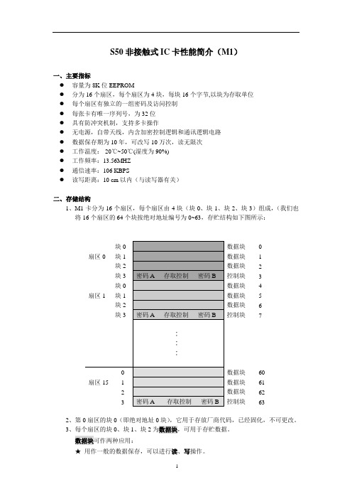
S50非接触式IC卡性能简介(M1)一、主要指标●容量为8K位EEPROM●分为16个扇区,每个扇区为4块,每块16个字节,以块为存取单位●每个扇区有独立的一组密码及访问控制●每张卡有唯一序列号,为32位●具有防冲突机制,支持多卡操作●无电源,自带天线,内含加密控制逻辑和通讯逻辑电路●数据保存期为10年,可改写10万次,读无限次●工作温度:-20℃~50℃(湿度为90%)●工作频率:13.56MHZ●通信速率:106 KBPS●读写距离:10 cm以内(与读写器有关)二、存储结构1、M1卡分为16个扇区,每个扇区由4块(块0、块1、块2、块3)组成,(我们也将16个扇区的64个块按绝对地址编号为0~63,存贮结构如下图所示:数据块0数据块 1数据块 2控制块 3数据块 4数据块 5数据块 6控制块7数据块60数据块61数据块62控制块632、第0扇区的块0(即绝对地址0块),它用于存放厂商代码,已经固化,不可更改。
3、每个扇区的块0、块1、块2为数据块,可用于存贮数据。
数据块可作两种应用:★用作一般的数据保存,可以进行读、写操作。
★用作数据值,可以进行初始化值、加值、减值、读值操作。
4、每个扇区的块3为控制块,包括了密码A、存取控制、密码B。
具体结构如下:密码A(6字节)存取控制(4字节)密码B(6字节)5、每个扇区的密码和存取控制都是独立的,可以根据实际需要设定各自的密码及存取控制。
存取控制为4个字节,共32位,扇区中的每个块(包括数据块和控制块)的存取条件是由密码和存取控制共同决定的,在存取控制中每个块都有相应的三个控制位,定义如下:块0:C10 C20 C30块1:C11 C21 C31块2:C12 C22 C32块3:C13 C23 C33三个控制位以正和反两种形式存在于存取控制字节中,决定了该块的访问权限(如进行减值操作必须验证KEY A,进行加值操作必须验证KEY B,等等)。
三个控制位在存取控制字节中的位置,以块0为例:对块0的控制:字节7字节8字节9( 注:C10_b表示C10取反)存取控制(4字节,其中字节9为备用字节)结构如下所示:字节6字节7字节8字节9( 注:_b表示取反)6、数据块(块0、块1、块2)的存取控制如下:例如:当块0的存取控制位C10 C20 C30=1 0 0时,验证密码A或密码B正确后可读;验证密码B正确后可写;不能进行加值、减值操作。

QUICK STARTUSB (type A)USB (type C)EthernetTS-9 Port 1TS-9 Port 2PowerNETGEAR Nighthawk M1ROHS declaration (reduction of hazardous substances). The manufacturer declares that your device is free from hazardous materials and complies with EU directive 2002/95/EC (commonly known as RoHS) and the amendments.PACKAGE CONTENTS• Nighthawk M1 Mobile Router and battery • Quick start guide• Manufacturer’s warranty card • USB Type-C cable •AC adapter1. Check the SIM card and insert the battery.a. Make sure that power to the mobile router is off.b. Remove the cover on the bottom of the mobile router.Place your thumbs on the arrows on the cover and press down while sliding the cover up.c. Check to see if a micro SIM card was inserted into the SIM card slot. If a micro SIM card was inserted, skip to step e. If a micro SIM card was not inserted, locate the micro SIM card in the box and continue with step d or contact Telstra.SAFETY FIRSTPlease read all the safety notices before using this device. This device is designed to be used at least 20 cm from your body. Do not use the device near fuel orchemicals or in any areas such as service stations, refineries, hospitals, or aircraft. Obey all warning signs where posted.Radio frequency safety information . The device includes an internal antenna. Foroptimum performance with minimum power consumption, do not shield the device or cover it with any object. Covering the antenna affects signal quality, might cause the router to operate at a higher power level than needed, and might shorten battery life.Radio frequency energy . Your wireless device is a low-power radio transmitter and receiver. When switched on, it intermittently transmits radio frequency (RF) energy (radio waves). The transmit power level is optimised for best performance and is automatically reduced when there is good quality reception. Maximum power is used only at the edge of network coverage so under most circumstances the power output is very low. Under poor network conditions the device transmits at a higher power, and might get hot, and battery life might be significantly shorter.Declaration of conformity – specific absorption rate (SAR). Your device is designed to be used at least 20 cm from the body. We declare that the product detailed in this manual, and in combination with our accessories, conforms with the essential requirements of the Radio Communications Standard (Electromagnetic IC Radiation Human Exposure) 2003 and the Australian Communications and Media Authority Section 376 of theTelecommunications Act 1997 when used at a distance of not less than 20 cm from the body.4GX Gigabit LTE Mobile RouterE6952. Download the NETGEAR Mobile App.Use the NETGEAR Mobile app to change your WiFi network name and password. You can also use it to play and share media, and enable the travel router feature.a. Connect your mobile device to the Internet.b. Download the NETGEAR Mobile mobile app from/mobileapps .d. Carefully slide the micro SIM card into the slot.e. Align the battery connectors and insert the battery.f. If you purchased a micro SD card, insert the cardinto the micro SD slot.g.Replace the mobile router cover.3. Power on your mobile router.Press and hold the Power button on the mobile router for threeseconds.To view the WiFi name and password, press and release the Power button to toggle through Nighthawk M1 router LCD displays.4. Connect your devices.a. Check to make sure that WiFi is enabled on your computer ormobile device and search for WiFi networks. Refer to the followingtable, or the manual for your WiFi-enabled device for further details on searching for WiFi networks.© NETGEAR, Inc., NETGEAR and the NETGEAR Logo are trademarks of NETGEAR, Inc. Any non-NETGEARtrademarks are used for reference purposes only. NETGEAR, Inc., 350 E. Plumeria Drive, San Jose, CA, 95134 USA.SUPPORT• From the Nighthawk M1 router home page, click the three dot icon in the upper right corner to access help and support files.• Direct all calls and support for PIN numbers, SIM card registration, account and billing information, network services, and other general enquiries to Telstra at 13 22 00.• Direct general enquiries to Telstra at .• See your warranty card for warranty and service information.• For additional information, visit /support to access the full user manual and to download firmware updates.1 Gbps CAT 16 LTE Advanced• Up to 4X carrier aggregation • LTE 4X4 MIMO• LTE 700/900/1800/ 2100/2600 MHz• 3G 850/900/2100 MHzSimultaneous Dual-Band WiFi• WiFi 802.11 b/g/n 2.4 GHz • WiFi 802.11 a/n/ac 5 GHzTECHNICAL SPECIFICATIONSClick the Internet Access icon, which is usually found on the bottom right side of your screen.Go to the WiFi and select Network Go to the Settings menu and tap the icon.NOTE: Your password is case-sensitive. NETGEAR stronglyrecommends that you change the default admin password.Advanced Configuration and FeaturesTo log in to the Nighthawk M1 router home page:1. Launch a web browser from a device that is connected to theNighthawk M1 router.2. In the address field of the web browser, enter http://m.home or http://192.168.1.1.3. In the Sign In field, enter your admin password (default is admin ), and click the Sign In button.Upload Media Files to the Nighthawk M1 RouterYou can upload media files to either a micro SD card or a USB drive connected to the Nighthawk M1 router. Micro SD cards and USB drives are sold separately. To enable media and Ethernet support, you must first select the Charge Only option under Settings > Router Setup > Use USB port for. To upload media files to the Nighthawk M1 router with a computer:1. Log in to the Nighthawk M1 router home page.2. Click the MyMedia tab.3. Drag and drop your files onto the page.Use the Nighthawk M1 Router to Charge Other DevicesIf your smartphone or other device is low or out of battery power, you can give it a boost by connecting it to the M1’s USB port A connector. Jump boost begins automatically once the devices are connected.LED StatusSlow blue blink The Nighthawk M1 router is ready.Fast blue blink The Nighthawk M1 router is transferring data.Slow amber blinkThe Nighthawk M1 router is not ready.Power KeyTurn on the router. Press and hold the Power key for three seconds.Turn off the router.Press and hold the Power key for five seconds.Wake the router.Press and quickly release the Power key.Switch between screens.Press and quickly release the Power key.。

THE FUTURE IS WHAT WE MAKE ITC7364B Duct TVOC SensorINSTALLATION INSTRUCTIONSThe TVOC sensor emulates the human perception of air quality much more than a CO 2 sensor and even detects odorless, potentially hazardous substances such as carbon monoxide.The CO 2-equivalent sensor output value was developed to allow the IAQ sensor to be used in select Demand Controlled Ventilation applications.Before InstallationRead these instructions carefully before installing and commissioning the transmitter. Failure to follow these instructions may result in product damage. Do not use in an explosive or hazardous environment, with combustible or flammable gases, as a safety or emergency stop device or in any other application where failure of the product could result in personal injury. Take electrostatic discharge precautions during installation and do not exceed the device ratings.NOTE 1: The air quality sensor requires a continuous calibration time of at least 3 weeks before the sensor algorithms provide accurate measurements. During this period the product-to-product readings may show large variations. The sensor may also indicate very high ppm readings during the initial calibration phase.NOTE 2: The air quality sensor is meant to provide an accurate measurement of INDOOR air quality. Diesel exhaust is not a component of indoor air quality and the sensor should not be used in such an application.MountingThe duct type sensor installs on the outside of a return air duct with the sampling tube inserted into the duct. Mount the sensor in an easily accessible location in a straight section of duct at least five feet from corners and other items that may cause disturbances in the air flow. Avoid areas with vibrations or rapid temperature changes.For proper function probe must be mounted with holes in probe aligned with air stream (sensor mounting holes oriented at 90 degrees relative to air stream)Drill a 7/8” or 1” hole in the duct at the preferredlocation and insert the probe into the hole to mark the enclosure mounting holes. Remove the unit and drill the two mounting holes. Clean all drilled holes of debris before mounting the device. Mount the enclosure to theduct with two #10 sheet metal screws (not included)such that the duct air flow is parallel with the vent holes in the probe (i.e.: air flows directly into the probe holes). To prevent air leaks, ensure the gasket is compressed around the probe between the device enclosure and the air duct. As shown in Figure 1.The enclosure has a hinged cover with a latch. Open the cover by pulling slightly on the latch on the bottom side of the enclosure and at the same time pulling on the cover, as illustrated in Figure 2.A 1/2” NPT threaded connection hole is provided in the left side of the enclosure. Screw the EMT connector or cable gland connector in until tight. See Figure 3. It is recommended that weatherproof conduit or cable gland fittings be used.Fig. 3. EMT ConnectionThis device has a half-wave type power supply so the power supply common is the same as the output signal common. Therefore, several devices may be connected to one power supply and the output signals all share the same signal common. Use caution when grounding the secondary of an AC transformer or when wiring multiple devices to ensure that the circuit ground point is the same on all devices and the controller.Ensure the controller Analog Input (AI) matches the TVOC voltage output signal type before power is applied. The voltage signals have a minimum loadrating. Follow the ratings in the Specification section or inaccurate readings may result.Connect the LINEAR output signal to a 0-5 or 0-10 Vdc analog input port on the controller as shown in Figure 6. The device is factory configured for 0-5 Vdc output signal but may be changed to 0-10 Vdc via the menu. Changing output signal may be done during set up of the device. This linear output signal represents to 0-2000 ppm CO 2-equivalent value.The ASO (Analog Stepped Output) output signal is a second voltage signal that represents the three air quality levels of GOOD, FAIR, and POOR. Each level may be set independently via the menu to any value between 0 and 10 Vdc. The factory default is GOOD = 2.5 V, FAIR = 5.0 V, and POOR = 7.5 V. This signal canDUCT TVOC SENSORWiring•Deactivate the 24 Vac/dc power supply until all connections are made to the device to prevent electrical shock or equipment damage. Follow proper electrostatic discharge (ESD) handlingprocedures when installing the device or equipment damage may occur•Use 18-22 AWG shielded wiring for all connections and do not locate the device wires in the same conduit with wiring used to supply inductive loads such as motors. Make all connections in accordance with national and local codes.• Connector layout is shown in Figure 5. Diagram shown includes all options. If option is not ordered, connector will not be present.•Connect the positive DC voltage or the hot side of the AC voltage to the terminal marked POWER. The power supply common is connected to the terminal marked COMMON as shown in Figure 6.•The device is reverse voltage protected and will not operate if connected backwards.Fig. 4. Secure CoverFig. 5. PCB LayoutPOWER LINEARCOM PWR ASO LINEARN.O.RELAYUP DOWN MENUTwo security screws are provided which can be installed to help secure the cover once settings and wiringconnections are complete. See Figure 4.Fig. 6. WiringDUCT TVOC SENSORalso be connected to a controller analog input, or it can be connected directly to a 0-5 or 0-10 Vdc input of a damper actuator for direct ventilation control as shown in Figure 7. In this way, the Indoor Air Quality Sensor can be used as a stand-alone device. Since all steps are completely adjustable, the device can also drive a reverse acting actuator.The relay output available on the RELAY terminals. The relay output terminals are completely isolated from other connections and are NOT connected to the signal COMMON terminal as shown in Figure 8. This signal can be used to directly control an alarm, a ventilation fan or may be connected to a digital input of a Building Automation System for status monitoring. Respect the relay contact specification as listed in this document.Set-UpVerify that the TVOC sensor is properly wired and all connections are tight. Apply power to the device and note that the LCD will display the software versionnumber for a few seconds and then the device will enter Warm Up mode. The Warm Up mode will last for five minutes and the LCD will count down the time. This time is required to allow the device and sensor to reach normal operating temperature. After the five minutes has expired the device will enter normal operation and the LCD will indicate the TVOC status and ppm value.OperationIn normal operation, the TVOC sensor will detect a broad range of reducing gases such as CO and VOCs and translate the measurement into a parts per million (ppm) CO 2 equivalent value. This value is displayed on the LCD in either ppm or % as set in the menu. The air quality value is also displayed as either GOOD, FAIR or POOR and these values can also be set via the menu.The GOOD, FAIR and POOR air quality levels control the Analog Stepped Output (ASO) signal. The ASO output signal comprises of three independently set voltage levels that can be used to directly control a damper actuator for three positions. The levels are set via the menu and each level can be set anywhere from 0-10 Vdc. The GOOD, FAIR and POOR air quality levels will also be displayed on the tri-color front panel LED. The LED colors are displayed as GOOD = green, FAIR = blue and POOR = red. If required, the LED operation can be disabled via the menu.The air quality value is also sent to the LINEAR output as a 0-5 or 0-10 Vdc signal to represent the 0-2000 ppm CO 2 equivalent. This signal can interface to any voltage analog input for logging or control purposes.The linear output scaling and ASO operation is shown below. Note that the ASO GOOD/FAIR trip level = 1000 ppm and the FAIR/POOR trip level = 1500 ppm. The ASO output levels are GOOD = 2.5 V, FAIR = 5.0 V and POOR = 7.5 V.The normally open relay will close when the airquality exceeds a pre-set trip point. The trip point and hysteresis value can be programmed via the menu such that the relay closes when IAQ > Relay Setpoint and opens when IAQ < Relay Setpoint - Hysteresis. By default, the relay has a one minute minimum onand off time to prevent short cycling. This feature may be disabled via the menu. The menu may alsobe used to test the relay function. The relay can be used to control an alarm, fan directly or to signal a digital input.Fig. 7. ASO WiringFig. 8. Relay WiringASODUCT TVOC SENSOROther features and configuration are described in the Setup Menu section.NOTE: The air quality sensor requires a continuous burn-time of at least 3 weeks before the sensoralgorithms provide accurate measurements. During this period the product-to-product readings may show large variations. The sensor may also indicate very high PPM readings during the initial burn-in phase.The TVOC sensor is meant to provide an accurate measurements of INDOOR air quality. Diesel exhaust is not a component of indoor air quality and the sensor should not be used in such an application.MenuThe menu may be accessed any time after the initial warm-up period. The menu is controlled by using the three buttons on the PCB labeled UP, DOWN, and MENU. All values entered are saved in non-volatilememory and will be restored correctly in case of a power failure.The menu has several items as shown below. To enter the menu, press and release the <MENU> key while in normal operation. This will enter the User menu step 1, pressing the <MENU> key a second time advances to step 2. Each press of the <MENU> key advances the menu item. The <UP> and <DOWN> keys are used to make changes to program variables by scrollingthrough the available options. When a value is changed, use the <MENU> key to save it to memory and advance to the next menu item. Actual menu displays with the factory default value are shown.NOTE: If no keys are pressed for 2 minutes, the menu will automatically exit.IAQ Unit ppmThe LCD displays the IAQ sensor reading from 450-2000 ppm. Use<UP> or <DOWN> to change from ppm (default) to % for 0-100 % display. 0-100% = 450-2000 ppm. Thissetting has no effect on the LINEAR output signal, it is always scaled 0-2000 ppm = 0-5/0-10 Vdc.<MENU>Press to advance to next menu item1. IAQ UnitIAQ G/F 1000 ppmThis sets the trip point from Good to Fair IAQ for the LED and ASO. Thefactory default is 1000 ppm. Use <UP> or <DOWN> to change from 700 to 1200 ppm in 25 ppm steps.<MENU>Press to advance to next menu item2. IAQ G/F IAQ F/P 1500 ppmThis sets the trip point from Fair to Poor IAQ for the LED and ASO. The factory default is 1500 ppm. Use <UP> or <DOWN> to change from 1300 to 1700 ppm in 25 ppm steps. Note that both IAQ trip points have a 25 ppm hysteresis built in.<MENU>Press to advance to next menu item3. IAQ F/P Analog Out 5VThe LINEAR analog output signaldefaults to 0-5 Vdc. It can be changed with <UP> or <DOWN> to 0-10 Vdc. The selected scale is always equal to 0-2000 ppm.<MENU>Press to advance to next menu item4. Analog Output ASO Good 2.5 VdcThis sets the ASO output voltage for the Good range. It can be set using <UP> or <DOWN> anywhere from 0-10 Vdc. Resolution is 0.1 Vdc. The ASO output changes accordingly.<MENU>Press to advance to next menu item5. ASO Good Output ASO Fair 5 VdcThis sets the ASO output voltage for the Fair range. It can be set using <UP> or <DOWN> anywhere from 0-10 Vdc. Resolution is 0.1 Vdc and ASO out updates.<MENU>Press to advance to next menu item6. ASO Fair Output ASO Poor7.5 VdcThis sets the ASO output voltage for the Poor range. It can be set using <UP> or <DOWN> anywhere from 0-10 Vdc. Resolution is 0.1 Vdc and ASO out updates.<MENU>Press to advance to next menu item7. ASO Poor Output IAQ Cal 0 ppmUse <UP> or <DOWN> to add orsubtract an offset to the IAQ signal. This can change from -200 to + 200 ppm in 10 ppm increments.<MENU>Press to advance to next menu item8. IAQ CalibrationRelay Test OFFRelay SP 1000 PPMUse <UP> or <DOWN> to toggle the relay on or off for testing.Use <UP> or <DOWN> to change the relay setpoint from 750-1500 ppm. Default is 1000. Resolution is 25 ppm.<MENU>Press to advance to next menu item<MENU>Press to advance to next menu item9. Relay Test 10. Relay Set Point Relay Hy 100 PPMRelay Dly YESRelay Op NOCan change the relay hysteresis to 20, 50, 100, or 200 ppm. Default is 100.By default, the relay has a 1 minute minimum on time and a 1 minute minimum off time to prevent fast cycling. This feature can be disabled here.By default, the relay is normallyopen as its non-energized state. Use <UP> or <DOWN> to change to NC (normally closed).<MENU>Press to advance to next menu item<MENU>Press to advance to next menu item<MENU> Exits the User menu and returns the normal operation. The LCD flashes“Menu Exits” for 3 seconds.11. Relay Hysteresis 12. Relay Delay 13. Relay Open/ClosedDimensionsTHE FUTUREIS WHAT WE MAKE IT® U.S. Registered Trademark © 2020 Honeywell International Inc.Printed in Canada 31-00414-01WEEE Directive 2012/19/EC Waste Electrical and Electronic Equipment directiveAt the end of the product life dispose of the packaging and product in a corresponding recycling centre. Do not dispose of the unit with the usual domestic refuse. Do not burn the product.Honeywell Building TechnologiesIn the U.S.:Honeywell715 Peachtree Street NE Atlanta, GA WARNING: This product can expose you to chemicals which are known to the State of California to cause cancer/birth defects or other reproductive harm. For more information go to .。
绪论一、版权申明本产品属于本公司所有,未经允许不得非法复制、仿制、销售。
二、酒店电子门锁系统简介电子门锁系统主要帮助酒店实现高度自动化管理,是一种使用简便化,管理多元化,消费一体化及安全性更高的智能电子门锁系统。
主要适用于宾馆、酒店。
三、系统组成1)硬件组成——门锁组成:由前锁体、后锁体、锁芯、附件四部分组成。
——前台计算机:奔腾或以上CPU,32兆内存,2.1G硬盘,800*600分辨率的彩显,两个可用的串口(读写卡片口、读开门记录口)。
——读写器:感应卡读写器。
——手持机:又称多功能控制器(或数据读取仪),用于感应卡电子门锁。
——电源供应:4节1.5V“AA”碱性电池。
——感应卡规格:MIFARE1感应卡片,使用寿命无限制。
2)软件组成——操作系统中英文WINDOWS系统。
——RX电子门锁管理系统。
3)卡体系组成卡由11种卡组成,共分四类;A、宾客类卡宾客卡:按指定时间段、指定楼层与房间、指定姓名发给宾客开门的钥匙卡,并可以开启反锁。
B、管理卡应急卡:可打开酒店内所有门锁的保安部总经理钥匙卡,包括反锁在内,开后门锁始终处于长开状态,即不用卡也可以开门,重新刷一下客人卡即恢复正常;总控卡:可打开酒店内所有门锁的总经理钥匙卡,包括反锁在内;楼控卡:可打开指定楼内所有门锁的大楼经理钥匙卡(反锁除外);层控卡:可打开指定楼层内所有门锁的楼层领班(主管)钥匙卡(反锁除外);组控卡:可打开编为一组的所有房间的钥匙卡(反锁除外)。
C、功能卡时钟卡:设置门锁的内部时间。
房号卡:设置门锁地址。
授权卡:加密,将其设定为某一个酒店(即可理解为给门锁命名)。
限制卡:限制指定卡片的使用。
记录卡:读取锁内开门记录。
系统安装使用说明一、系统安装本系统的安装过程非常简单,一般几分钟即可安装完成,安装过程如下:A、操作系统的安装请参照Windows98(以下称Windows)的安装手册、或由供应商代为安装。
B、门锁管理软件的安装a.给微机上电,启动Windows,插入软件。
SNOPPA M1 User ManualV1.02017.03TipsImportantInstall the Snoppa AppScan the barcode below to download the Snoppa App, or search for “Snoppa App” on the App Store or Google play, and install the app on your mobile phone.Snoppa App only support iOS 8.0 or later, and Android 5.0 or later.legendUSING THIS MANUALACKNOWLEDGEMENTThanks for choosing Snoppa M1 handheld 3-axis motorized stabilizer, which is mainly designed for smartphones.With the Snoppa’s advanced 3-axis stabilizing algorithm and hardware, it can precisely detect the smartphone’s position and control the built-in motors to compensate for natural arm movements, Balancing the smartphoneand eliminate video shake.FOLDED M1 EXPANDEDTILTPANROLLProduct Diagram[1] PAN Motor[2] TILT Motor[3] Counterweight[4] ROLL Motor[5] 1/4 screw mount[6] Foldable mobile phone holder[7] Indicator light & Function Button[8] micro USB charging port[9] GripUSE SNOPPA M1Power On and Power OThe M1 can work with or without Snoppa AppWhen using the device without the Snoppa app you can directly power on the stabilizer through the indicator button, change tracking modes, and use a third party camera app (or stock camera app).When using the Snoppa app, the M1 will need to be connected to the smartphone through Bluetooth, and can be controlled by the Snoppa app. With the app you have more special shooting features like panorama photography or motion time-lapse etc.A. Without Snoppa AppB. With Snoppa App Collapse the tilt-axis to the grip, quit Snoppaapp, and the gimbal will power off after 20 seconds without any operation.Turn on the Bluetooth of the phone, launch Snoppa App, click the Bluetooth icon on the edge of the interface and enter the Bluetooth setting.Connect to SNOPPA -xxxx Default password: 000000To reset the password and device name, pressthe button and hold for 10 seconds.Pull out the grip, rotate the tilt-axis of the phone until the intersection angle is more than 60 degree, and M1 willstart to work automatically.Power onPower oOnce connected the green light on the gimbal will start blinking, and the Bluetooth icon will change and dispaly the gimbal battery level.Indicator Light / Function ButtonThe indicator light underneath the phone holder is also a function button.OperationButton Operationpress + press & hold for 2 secDiscreptionturn off M1turn on M1switch tracking modes /reactivate bluetoothpress one time press & hold for 2 sec Press & hold for 10 secReset BluetoothIndicator light/Function button(Using without App )Pressing the indicator button is invalid when the stabilizer is connected by Snoppa App.Standby & Wake upSTANDBY OFF MODE WAKE UPCollapse the tilt-axis to the grip, the gimbal will enter standby mode, and all the motors will stop working.Working with Snoppa App: collapse the tilt-axis to the grip, exit Snoppa app, the gimbal will power off automatically after 20 seconds without any operation.Working without Snoppa App: Press & hold for 2 seconds, the gimal turns off immediatly.Within 30 minutes without any operation, the Bluetooth will enter sleep mode, and the stabilizer will not be found in the Bluetooth device list.Press the indicator button to wake up the Bluetooth of stabilizer, the indicator will flash green, and the device will show up in the device list and can be connected.60TILTRotate the tilt-axis down until the intersection angle is larger than 60 degree, motor stabilization will be reactivated.BLUETOOTHSLEEP & WAKEUPOverload ProetectionWhen some axis is stuck for 1 second, the auto circuit protection will be triggered, and the stabilizer will enter standby mode automatically, all the motors stop working.Please hold the handle when using (the picture on the left).When wrongly hold on the middle part (picture on the right), the handle will spin for a while and stop, and trigger the standby mode, all the motors stop working.12Tracking ModesSwitch tracking modes With Snoppa app connected without Snoppa apppress indicator button (switch on a loop)Pan trackPan trackomni track lockPan camera by moving the grip left or right.Shoot in a fixed direction no matter how the grip moves.Pan and tilt camera by moving the grip up& down, left & right.Omni trackpantiltpanAngle AdjustmentHold and rotate the mobile phone to the angle you want and hold it for one second.In Lock Mode, pan and tilt angle can be both adjusted manually.In Pan Track and Omni Track modes, only tilt angle can be adjusted manually.PAN TRACK LOCKOMNI TRACKHorizontal & Vertical shootingAuto switch:Manual:raise the grip up to 45 degree, and the phone holder will turn automatically to horizontal direction.directly hold the mobile phone and rotate to a normal horizontal direction.Horizontal shootingVertical shootingHold the grip vertically, and turn the phone 90 degree left or right, and hold for one second .For vertical shooting it is essential to the propercounterweight installed to properly balance different phones.Use the provided magnetic tool to pull the counterweight out.When shooting vertically, please make sure to choose the proper counterweight to match phones of different weights.CHARGINGBuilt-in Li-Po battery, which is not replaceable Charge the gimbal with a micro USB cable(connect to power bank or phone adapter or pc etc.) When charging the gimbal, the indicator will blink green, and will turn constant green when fully charged.USBBatteryType Li-PoCapacity 1050 mAhOutput voltage 7.4VEnergy 7.8WhBattery life 500 cyclesCharging time within 1.5 hoursRuntime 4 hoursIn order to pull out the grip When you want to collapse the gimbal,grab the top part with one hand and align the handle, then use your other hand to tap push the bottom of the handle. Don’t put your hands near the middle to avoid getting pinched.SNOPPA APPIn addition to the basic stabilizing features, with the Snoppa App, there are other useful shooting modes like panorama, motion time-lapse etc. which can make videography more interesting and easy.User Interface of Snoppa App[1][1][2][3][4][5][6][7][8][10][9]shooting parametersshutter light white balance focal distance ISO[2]Shooting mode videopanorama: motion time-lapseautomatic 270 panoramic [3] Start/stop recording [4] Switch front/back camera [5]Tracking modepan track:Roll and tilt are locked, pan camera by moving the grip left & right.lockRoll, tilt and pan are all locked, shoot in a fixed direction no matter how the grip moves omni track:Roll is locked, pan and tilt camera by moving the grip up & down, left & right.[6] GallaryVideos and images will be automaticly saved into Gallary. User can highlight videos by star level, and save to system photo album.there are extra settings includingIf rotation is needed for time-lapse shooting, please set the tracking mode to LOCK mode[7] Reference lineThere are three options:None/Grid Line/Grid+DiagonalsResolution & Frame rate540p HD 60fps; 720p HD,30fps ; 1080p HD,30fps 1080p HD,60fps ; 2160p HD,30fpsMay be different depending on phone models.[8][9] system settingBlueTooth Settingsto choose and connect M1 device through Bluetooth Gimbal Settingsto adjust tracking speed, and perform calibration Firmware Infoto check and update firmware User Guideto read the built-in user guide[10] Bluetooth connectionOnce bluetooth is connected, the icon will change and dispaly the battery level.connecteddisconnectedAUTO CALIBRATIONNormally the gyro sensor is sensitive to the surround-ing environment, and maybe out of balance due to the previous transport, you can perform the auto calibration procedure in the Snoppa App(Choose "Drift Calibration" or "Level Calibration" in the "Gimbal Settings" )Drift calibrationWhen the stabilizer is automatically rotating slowly, drift calibration is needed. Before carrying out the calibration, place the stabilizer on a surface and keep it still. The whole process will take 1~2 minutes, make sure the stabilizer is kept still during calibration, otherwise it can’t get proper calibration result.Level calibrationWhen finding the stabilizer is leaning to one side after startup, level calibration is needed. Please follow the instructions on the screen to perform the level calibration.FIRMWARE UPDATEIn order to get the best performance out of your gimbal, please make sure it is upgraded with the latest firmware. When the Snoppa app is launched a pop-up message will appear on screen if a new firmware upgrade is available, prompting you to update.Make sure your smartphone has internet access. Connect the gimbal with Snoppa App by Bluetooth, enter the setting menu, choose “Firmware Info”.You can also manually check for and upgrade to the new firmware when a new upgrade is available.BUILT IN USER GUIDEIn the setting menu, there’s a built-in “User Guide”, introducing both the M1 hardware and Snoppa application. You can open it whenever necessary.SPECIFICATIONSITEMModel DimensionsWeight (battery included) Controllable range Mobile phone width range WirelessRuntimeBATTERYTypeCapacityOutput voltage EnergyBattery lifeCharging temperature Operating temperature SPECSSP-M1Folded 208 x 53 x 43mm Unfolded 266 x 53 x 43mm 450 gPan: 360˚ free rotation Tilt: ±100°Roll: 360˚ free rotation 58-85mmBluetooth Low Energy 4.0 4 HoursLipo1050mAh7.4V7.8Wh500cycles0°~ 45°-10°~ 45°深圳市随拍科技有限公司© 2015 Snoppa Technology. All Rights Reserved.If you have any questions about the document, Please visit our website: 。
M1/M1pro(g36)手表〔平安守护〕快速使用指南请您在使用之前认真阅读使用说明书,以便正确安装和快速使用,产品颜色请以实物为准!一、使用前准备检测设备型号是否正确,配件是否齐全。
选择GSM 网络的SIM 卡,参考经销商的意见。
〔装卡前请先关机〕手表SIM 卡需要开通GPRS 功能和来电显示功能。
在端安装APP 客户端,客户打量情可询问你的经销商条形码或者二维码,用来注册用户二、产品功能● GPS+基站双模定位方式● 客户端或者电脑gprs 效劳平台,双重控制方式● GPRS 实时定位,跟踪,监控● 本● 对讲● 健康● 足迹● 手表闹钟● 平安区域● SOS 紧急报警● 手表撤除报警● 低电量报警● 远程关机三、手表介绍四、屏显说明五、客户端〔平安守护〕操作说明 5.1 APP 注册按键1亲情号码1开机键挂 键录音键GSM 、GPS 、电池爱心、语音信息时间、日期撤除表带标志计步数〔app 关闭计步显示星期数〕 usb 接口 按键2亲情号码2 本sos 键 接 键 播放录音键登录前需要先手动注册账号,注册的id通过扫描条形码或者手动输入,用户名不少于4个字符〔字母或者数字〕,id和用户名都是唯一的不能重复,其他信息客户可自行输入,密码可修改。
注册界面如以下图:5.2 登录5.2.1 APP功能菜单界面注册完成,在登录界面输入正确的账号和密码,点击登录,进入主界面。
主界面如以下图所示:局部功能的说明:⑴对讲:实现手表和app的语音对话。
App发送语音:启动录音后,app开始录音并发送给手表,最长语音15秒。
手表端短按sos 键播放录音。
手表录音:长按开机键开始录音,松开后手表发送录音,最长录音15秒。
App端收到语音有提示信息(收到语音的时间长短与网络状况有关)。
⑵地图:实时查看手表的位置。
地图界面可显示手表和app的位置,点击“定位〞手表开始实时定位3分钟,上传间隔为10秒,3分钟后恢复到默认的工作模式。
soopiim1说明书下载“易微联”手机APP1.安卓手机在各大应用市场或者百度搜索“易微联”下载APP。
2.苹果手机在appstore搜索“eWeLink”安装APP。
二、设备接线安装示意图替换您风扇灯原有的驱动,接线如下三、添加设备流程安装好设备后,上电。
1.进入配对模式,以下两种方式都可以让设备进入配对模式:长按iFan02上的app配对按钮直到您听到iFan02发出哔哔哔-哔哔哔-哔哔哔…的声音。
长按2.4G遥控器的app配对按钮直到您听到iFan02发出哔哔哔-哔哔哔-哔哔哔…的声音。
2.在APP点击添加设备图标“+”。
请根据配对图标快速配对TOUCH,点击下一步。
3.APP会自动选择您的家庭WiFi,输入密码。
3.1如您家里的WiFi不需要密码则留空不填即可。
3.2设备使用的是2.4Gwifi通信协议,暂不支持5G无线路由器。
4.下一步,APP开始自动搜索设备并绑定到您的账号下,完成后可以给您的设备命名。
5.完成命名后设备如果显示不在线,请稍等两分钟,设备正在尝试通过您的无线路由器连接到云端服务器。
四、用2.4遥控器控制首先,将电池装进遥控器背后,您需要一把一字螺丝刀来打开电池盖。
具体的按钮对应功能如图所示:五、app功能1.远程开关风扇和灯您可以在独立地开关风扇和灯,具体的控制界面如下:2.远程调节风速一共有四个风速:低、中、高和智能风3.远程调灯光(如果您的灯支持调光的话)点击灯的开关按钮,你就可以调节灯光色温。
如果您的灯不支持调光,点击该按钮只会开关灯。
4.主账号分享设备给他人功能主账户(第一个添加了该设备的账户)可把设备分享给好友,实现多人共同控制。
被分享账号必须是已注册的易微联账号,被分享时请保持登录在线状态。
分享的同时可以勾选定时器权限(新增、修改、删除、启用)。
5.定时(仅支持灯)设置设备状态、时间和日期,您的设备就会在设定的时间自动执行定时任务。
6.延时定时(仅支持灯)即快速定时,更快捷直观的定时模式,N分钟、N小时、N天后执行。
绪论一、版权申明本产品属于本公司所有,未经允许不得非法复制、仿制、销售。
二、酒店电子门锁系统简介电子门锁系统主要帮助酒店实现高度自动化管理,是一种使用简便化,管理多元化,消费一体化及安全性更高的智能电子门锁系统。
主要适用于宾馆、酒店。
三、系统组成1)硬件组成——门锁组成:由前锁体、后锁体、锁芯、附件四部分组成。
——前台计算机:奔腾或以上CPU,32兆内存,2.1G硬盘,800*600分辨率的彩显,两个可用的串口(读写卡片口、读开门记录口)。
——读写器:感应卡读写器。
——手持机:又称多功能控制器(或数据读取仪),用于感应卡电子门锁。
——电源供应:4节1.5V“AA”碱性电池。
——感应卡规格:MIFARE1感应卡片,使用寿命无限制。
2)软件组成——操作系统中英文WINDOWS系统。
——RX电子门锁管理系统。
3)卡体系组成卡由11种卡组成,共分四类;A、宾客类卡宾客卡:按指定时间段、指定楼层与房间、指定姓名发给宾客开门的钥匙卡,并可以开启反锁。
B、管理卡应急卡:可打开酒店内所有门锁的保安部总经理钥匙卡,包括反锁在内,开后门锁始终处于长开状态,即不用卡也可以开门,重新刷一下客人卡即恢复正常;总控卡:可打开酒店内所有门锁的总经理钥匙卡,包括反锁在内;楼控卡:可打开指定楼内所有门锁的大楼经理钥匙卡(反锁除外);层控卡:可打开指定楼层内所有门锁的楼层领班(主管)钥匙卡(反锁除外);组控卡:可打开编为一组的所有房间的钥匙卡(反锁除外)。
C、功能卡时钟卡:设置门锁的内部时间。
房号卡:设置门锁地址。
授权卡:加密,将其设定为某一个酒店(即可理解为给门锁命名)。
限制卡:限制指定卡片的使用。
记录卡:读取锁内开门记录。
系统安装使用说明一、系统安装本系统的安装过程非常简单,一般几分钟即可安装完成,安装过程如下:A、操作系统的安装请参照Windows98(以下称Windows)的安装手册、或由供应商代为安装。
B、门锁管理软件的安装a.给微机上电,启动Windows,插入软件。
b.我的电脑/锁管软件系统下,选择M1安装盘目录下的文件SETUP.EXE,运行此文件即可。
c.按照提示,选择安装路径,完成安装过程。
d.安装完成后,不需重新启动计算机。
二、软件启动启动本软件的方法:软件安装完毕后,单击电脑屏幕左下角的“开始”,在程序中找到RFLOCK目录,单击此目录中的RFLOCK,即可启动本软件。
说明:a.系统启动时,需要输入操作员的代号和密码,如果输入系统没有登记的代号,或者输入的密码错误,就无法进入系统。
b.系统安装后,有一个缺省的系统员USER,第一次进入本系统可使用此系统员,不需输入操作员密码,可以直接进入。
第一次使用本软件,可根据实际情况,修改管理员密码,增加管理员和一般操作员。
操作方法见“锁管系统”一节。
第一章锁管系统锁管系统分为“员工开门卡”、“初始化卡”、“限制卡”、“开门记录”、“系统维护”、“其他”。
一、员工开门卡员工开门卡分“应急卡”、“总控卡”、“楼控卡”、“层控卡”、“组控卡”等部分。
图1-11、应急卡应急卡:能开启整个酒店的所有房间房门,包括反锁。
使用应急卡后,门锁始终保持长开状态,即在门外,不需用任何卡片均可开启房门,若想恢复正常状态,只需重新刷一下此房间的客人卡即可。
说明:如果应急卡丢失,为了安全起见,必须做该应急卡的限制卡。
应急卡在使用后应立即注销,使其无效,需要使用时再重新配置。
具体操作方法如下:将光标移动到“应急卡”上然后点击,系统会弹出图1-21)输入持卡人姓名,起始时间(如不需更改时间,则系统内自动显示的时间与电脑时间同步)、备注;2)点“发卡”即可设置完毕。
图1-22、总控卡总控卡:由酒店管理人员持有,能开启整个酒店的所有房间,包括反锁。
说明:如果总控卡丢失,必须做该总控卡的限制卡。
由于此卡可开启本酒店内所有房间,包括反锁,则持有此卡人数越少越好,最好,持卡人在本酒店中占有一定比例的股份。
以免发生客人物品遗失现象。
具体操作方法如下:将光标移动到“总控卡”上然后点击,系统会弹出图1-31)输入持卡人姓名、起始时间(如不需更改时间,则系统内自动显示的时间与电脑时间同步)备注(备注内可提示持卡原因等);2)点“发卡”即可设置完毕。
图1-33、楼控卡楼控卡:由酒店管理人员持有,开启指定大楼的所有房间,不可开启反锁,并具有时间限制。
说明:如果楼控卡丢失,必须做该楼控卡的限制卡。
具体操作方法如下:将光标移动到“楼控卡”上然后点击,系统会弹出图1-41)输入持卡人的姓名、有效期、有效时段、备注(备注内可提示持卡原因等);2)输入允许其管理的大楼的代号3)点“发卡”即可设置完毕。
图1-44、层控卡层控卡:持卡人是楼层管理人员,它是由酒店管理人员发卡,该卡有时间性,能开启指定大楼的指定楼层的所有房间,不可开启反锁。
具体操作步骤如下:将光标移动到“层控卡”上然后点击,系统会弹出图1-51)输入持卡人姓名、有效期、有效时段、备注(备注内可提示持卡原因等);2)输入允许其管理的大楼代号、层号3)点“发卡“即可设置完毕。
图1-55、组控卡服务员卡:持卡人是酒店服务人员,它是由酒店管理人员发卡,该卡有时间性,能开启指定房间(但不能开启反锁),此指定房间范围是用组号卡设置过的房间,详情见下节。
具体操作步骤如下:将光标移动到“组控卡”上然后点击,系统会弹出图1-61)输入持卡人姓名、有效期、有效时段、备注(备注内可提示持卡原因等);2)输入允许其管理的组号。
3)点“发卡“即可设置完毕。
图1-6二、初始化卡初始化卡分为“授权卡”、“房号卡”、“组号卡”、“时钟卡”图2-11、授权卡授权卡:又称复位卡,是将门锁加密,即给购买回来的门锁命名。
是门锁安装到门上之后,设置方法中的第一步。
具体方法:用任意宾客卡放到发卡器上,点初始化卡中的授权卡,点“确定”即可。
用制作好的授权卡,到需要进行初始化的门锁上刷一下,待绿灯亮后拿开,门锁初始化成功。
2、房号卡房号卡:房号卡的功能是下载新的房间地址到门锁,它是由酒店管理员发卡,该卡只是在首次安装门锁时以及门锁地址需要重新设置时才使用。
将光标移动到“房号卡“上然后点击,系统会弹出图2-21)输入大楼代号(数字0-255)、大楼名称、层号、房号(4位数字)、房间类型、房价;2)点“增加”即新的大楼房间产生;3)点“发房号卡”即可发出一张该房间的房号设置卡,用此张卡片到相对应房间门锁上刷一下,绿灯亮后拿开,该房间地址设置成功。
如增加多个房间则反复重复上述步骤即可。
说明:每个房间必须分别设置一张房号卡,即一张卡片不能同时设置成几个房间的房号卡。
另:删除房间,将所要删除的房间的楼号,名称、层号、房号输入后,点删除一个房间即可;删除大楼,将所要删除大楼的代号,名称输入后,点删除一栋大楼即可。
图2-23、组号卡组号卡:功能是将不同大楼,不同楼层的不同房间编为一组,便于酒店服务人员使用。
这样,服务人员持一张卡片,即可开启任意编为一组的房间。
将光标移动到“组号卡”上然后点击,系统会弹出图2-3/2-41)看图2-3,首先将“清除组号”、“全部组号”选定,然后在发卡机上放一张宾客卡,点发组号卡;2)用这张卡片,先到本酒店所有门锁上刷一遍,清除原组号内容。
3)看图2-4,将“设置组号”、“部分组号”选定,任意设定一个组号,然后在发卡机上放一张宾客卡,点发组号卡;4)用这张卡片,到本酒店需要编为一组的房间上刷一下,即可。
注:此操作结束后,即可用第一节里介绍的组控卡开启房间。
图2-3图2-44、时钟卡时钟卡:功能是下载新的时间到门锁,它是由酒店管理人员发卡,该卡只是在首次安装门锁时以及门锁时间需要重新设置时才使用。
具体操作步骤如下:将光标移动到“时钟卡”上然后点击,系统会弹出图2-31)输入姓名(可以任意输入),2)点“发卡”即可。
说明:整间酒店只需发一张时间卡即可,然后在每间需要调整时间的门锁上刷一下,绿灯亮后移开,设置成功。
图2-5三、限制卡限制卡分为“挂失卡”、“封闭卡”图3-11、挂失卡挂失卡:用于单独限制某房间的使用,如客人不慎将开门卡丢失,只需在发行客人卡里面把新客入住点上钩即可,不需发行挂失卡,如除客人卡外的其他卡片丢失,则应立即到总台发行该丢失卡的挂失卡,以免客人财物损失。
具体操作步骤如下:将光标移动到“挂失卡”上然后点击,系统会弹出图3-21)将光标点在需制作挂失卡的房号上;2)点“发挂失卡”即可。
3)将这张单限卡片拿到对应的房间门锁上刷一下,绿灯亮后拿开,该丢失的卡片不可再直接开启房门。
如该丢失卡拾回,则拿回总台重新发行即可。
图3-22、封闭卡封闭卡:发行该卡将限制本酒店所有房间的使用。
将此封闭卡拿到本酒店所有房间,刷卡,绿灯亮后拿开,既可限制本酒店所有房间的使用。
说明:建议发行此卡之前,一定要考虑清楚,不可随意发行。
如果已封闭了哪个门锁的使用,只需重新发行授权卡即可恢复。
刷过授权卡之后,门锁之前的记录仍存在门锁内,可用数据仪读取到。
图3-3四、开门记录开门记录分为“发行记录卡”、“显示开门记录”等部分。
图4-11、发行记录卡发行记录卡:用任意空白宾客卡,放在发卡器上面,点发行记录卡,即可,拿到要读取记录的门锁上,先用此张记录卡在门锁上刷一下,然后再用感应式数据仪对着门锁感应区读取,绿灯亮后,表示读取完毕。
2、显示开门记录显示开门记录:将数据采集仪拿到需要读取记录的门锁上,感应待绿灯亮后拿开,拿回酒店前台,连接电脑串口,将光标移动到“显示开门记录”上然后点击,即可显示此房间门锁最近的256条开门记录,包括机械钥匙在内。
图4-2五、系统维护系统维护分为“发卡记录”、“登录记录”、“客人记录”、“操作员管理”、“系统注册”等部分。
图5-11、发卡记录发卡记录:打开此菜单,可查询所有卡片的发行记录,其中包括发行卡片卡号(按由小到大的顺序自动排列)卡片的类型、持卡人、有效期、有效时段、房号、发卡人以及发卡的时间等内容。
图5-22、登录记录登录记录:此菜单是用于查询操作员每次登录以及退出本系统的时间,管理员可以在登录此窗口后,删除其他管理员以及一般操作员的登录记录具体操作步骤如下:将光标移动到“登录记录”上然后点击,系统会弹出图5-21)将光标点在想删除的操作员的登录时间上,系统会自动记录下此时间为“起始时间”,再将光标移到下一个想删除的操作员的登录时间上,系统会自动记录下这个时间为“结束时间”;2)点“删除”键,即可删除在“起始时间”至“结束时间”段之内的所在登录的管理员以及一般操作员的信息。
说明:删除记录内容至少为2个,即一个做为起始时间,一个做为结束时间。
图5-23、客人记录客人记录:用于查询所有客人的入住记录的情况,内容包括:客人编号、姓名、房间号码、入住时间,预计退房时间,实际退房时间,证件号码、备注等。