P+F安全栅组态步骤(必备手册)
- 格式:pdf
- 大小:1.35 MB
- 文档页数:10
安全栅作业指导书一、作业目的:安全栅在线故障处理过程中,应采取的预防措施,确保装置安全运行。
二、适用范围:大聚P+F及重油LB930安全栅。
三、采用标准:以P+F安全栅和LB930安全栅为例四、工作原理:1.大聚安全栅结构工作原理:大聚安全栅使用德国P+F集团的齐纳安全栅,包括多种型号。
KF系列隔离栅的现场侧端子与系统侧端子用不同颜色区分,如果有两组或以上的端子,可通过在端子上设置编码,使用端子组之间不会互相插错。
采用轨道供电后,隔离栅的配电就变得简单,易于掌握,不易出错,并且能很方便地实现冗余供电。
除了信号隔离功能外,还可以实现多种其他的功能,如信号分配,信号转换,报警设定等。
齐纳安全栅的作用,实际上是不让高电压或大电流传到现场仪表,使现场仪表的能量始终在安全范围之内,从而实现系统的本质安全防爆。
其结构原理如图1-11.1所示,电路由快速熔断器FA1,限压元件VD1、VD2 (齐纳二极管或二极管),限流电阻R1(电阻器或非线性元件)三部分组成。
正常操作条件下,非本安端1、2 之间所加的电压低于最高电压Vmax(更低于齐纳二极管的齐纳电压),此时VD1、VD2处于不导通状态,除有极微小的漏电流以外,是“开路”状态,安全栅电路等效于一个电阻串联在信号回路内,只要漏电流小于规定值,安全栅电路不会影响系统的正常工作。
当非本安端发生故障,例如在非本安端1、2之间因某种原因混入高电压,使齐纳二极管VD1、VD2 反向击穿,呈“导通”状态,此时齐纳二极管VD1、VD2 把混入的高电压限制在齐纳电压上,在安全栅的本安端3、4 上不会出现高电压,齐纳二极管一旦导通以后,其电流急剧上升(雪崩过程)把串联在电路中的熔断器FA1 瞬时熔断,切断了至现场的高电压,防止了高电压引爆现场爆炸性物质的危险,从而保护了现场设备及人员的安全。
当现场(危险区内)发生故障,例如负载短路了,安全栅电路中的限流电阻R1立即起限流作用,把短路电流限制在某一个电流值之内,这个电流值是安全值,故现场也是安全的。
P+F安全栅及现场总线产品德国Pepperl+Fuchs公司成立于1945年。
1958年,P+F发明的世界首例本安型接近开关及与之世界的隔离式安全栅使工业防爆应用领域发生了全新的变革。
如今,P+F公司已发展成为世界上最大、最有经验的本安接口生产商。
其安全栅品种之丰富、处理特殊应用难题之能力一直处于世界领先地位。
其产品应用遍及石油、天然气、化工、石化、医药等存在易燃易爆危险场所的工业领域。
P+F积极推动本质安全技术面向现场总线时代的新变革。
P+F远程I/O型隔离栅RPI和本安型远程I/O系统IS-RPI已经开始对本安接口的应用产生深远的影响。
P+F的FieldConnex现场总线产品家族包含了将现场总线主机与现场仪表相连接的全套配件产品,包括各种网桥、现场总线配电器、现场总线中继器、现场总线I/O模盒、接线盒、现场总线安全栅、快速接插件等现场总线产品,更使本安防爆的现场总线全面进入实用阶段。
P+F公司的产品不仅符合德国、欧洲和国际(IEC)标准,其专业化的研究和开发工作,还曾经并继续为这些标准的制定提供依据。
P+F公司的所有生产和开发机构均获得ISO9001质量保证体系认证。
其产品还获得包括美国(FM)、中国(NEPSI)等世界诸多国家的防爆认证。
为确保完善的就近服务,P+F公司的过程自动化部(PA)和工厂自动化部(FA)在世界各主要国家和地区设立子公司和办事处。
在中国,P+F公司在北京、上海设有代表处和子公司,并在广州等全国各主要大城市设有办事机构。
P+F公司不仅仅是防爆技术专家,其经验和创造力还从其产品本身延伸至系统配套方面。
本样本将详述P+F齐纳栅、隔离栅与DCS和ESD控制系统配合的典型方案,并提供现场总线的配电、防爆和连接的典型方案。
P+F公司备有安全栅产品的详细的原版书面样本和CD-ROM样本及多种应用指南。
P+F 隔离栅的优势:轨道供电大部分隔离栅需要供电.当隔离栅使用数量较大时,给隔离栅配电不是一件轻松的工作.为了简化隔离栅的配电,P+F公司发明了轨道供电方式。
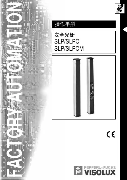
F A C T O R Y A U T O M A T I O N SLP/SLPC SLP/SLPCM 操作手册安全光栅With regard to the supply of products, the current issue of the following document is applicable: The General Terms of Delivery for Products and Services of the Electrical Industry,published by the Central Association of the Electrical Industry (Zentralverband Elektrotechnik und Elektroin-dustrie (ZVEI) e.V.)in its most recent version as well as the supplementary clause: "Expanded reservation of proprietorship"We at Pepperl+Fuchs/VISOLUX recognize a duty to make a contribution to the future.D a t e o f i s s u e 02/25/0238.3.4Test of error enable connection (RESET)...................................... 27SLP/SLPC 和 SLP/SLPCM 安全光栅目录章 页1 使用目的 ............................................ 62 产品描述 ............................................ 62.1 系统特点 .................................................... 62.2 工作原理 .................................................... 72.3 原理框图 .................................................... 83 电气连接 ........................................... 103.1 SLPC(M)端子区 .............................................. 103.2 SLPC(M)连接器 .............................................. 123.3 Muting 灯连接 / 灯插座(仅对SLPCM...-L...) ................ 133.4 SLP发射器的连接............................................. 144 状态指示 ........................................... 155 工作模式 ........................................... 165.1 启动 / 重启锁(Restart).................................... 175.2 继电器监控.................................................. 175.3 Muting(SLPCM)............................................. 185.3.1 工作原理.................................................... 195.3.1.1 平行或连续Muting方式下对Muting传感器的评估......................... 195.3.1.2 时间窗口限制或保护光束限制Muting方式下的Muting监控 ......................... 205.3.2 Muting传感器................................................ 225.3.2 Muting指示灯................................................ 225.4 紧急Muting(仅对SLPCM)..................................... 226 光栅的安装 ......................................... 237 电气安装布置 ....................................... 258.2 反射镜的布置................................................ 268.1 调整保护光束................................................ 268 调试 ............................................... 268.3 功能测试.................................................... 278.3.1 NCSE检测能力测试............................................ 278.3.2 Muting功能测试(仅对SLPCM)................................. 278.3.3 启动/重启锁和启动能力测试................................... 278.3.5 继电器监控测试.............................................. 288.3.6 OSSD工作原则................................................ 28D a t e o f i s s u e 02/25/02416.1Construction and equipping of safety equipment......................... 4416.2Use and installation of protective equipment................................ 44Please note!This instruction manual contains instruction explaining the intended use of the product and serves as a protection from danger. It must be read and observed by all persons who make use of, care for, maintain and monitor this product. This pro-duct can only accomplish the tasks for which it is intended if it is used, cared for,maintained and monitored in accordance with the instructions of Pepperl+Fuchs/Visolux.The warranty undertaken by Pepperl+Fuchs/Visolux for this product becomes null and void if it is not used, cared for, maintained and monitored in accordance with the instructions of Pepperl+Fuchs/Visolux.Before this product is used, an evaluation must be undertaken to determine whe-SLP/SLPC 和 SLP/SLPCM 安全光栅9 定期检查 ........................................... 2810 故障诊断 ........................................... 2911 技术参数 ........................................... 3011.1 电气参数及特性.............................................. 3011.2 外形尺寸.................................................... 3212 附件 ............................................... 3412.1 SLP安装支架................................................. 3412.2 SLP反射镜................................................... 3512.3 SLP保护镜................................................... 3612.4 SLP保护镜固定架............................................. 3612.5 SLP辅助对齐瞄准器........................................... 3612.6 SLP激光辅助对齐工具......................................... 3712.7 电缆连接器.................................................. 3712.8 电缆扎带.................................................... 3713 订购信息 ........................................... 3814 电路图示例 ......................................... 4015 术语表 ............................................. 4316 标准 ............................................... 4417 证书 ............................................... 45D a t e o f i s s u e 02/25/025ther it is suitable for the application at hand. Selection and use are not subject to influence on the part of Pepperl+Fuchs/Visolux. Our liability is thus restricted to consistent quality of the product.The product must be monitored and maintained by competent professionals. A re-cord must be kept of the results of inspections and maintenance tasks. Only ori-ginal Pepperl+Fuchs/Visolux parts must be used for repair jobs.The operator is not permitted to make changes to the machines or components thereof, or make use of defective or incomplete machines or components. Repairs to machines or components must only be performed by Pepperl+Fuchs/Visolux or by authorized workshops. Such workshops are responsible for acquiring the latest technical information about machines and components from Pepperl+Fuchs/Viso-lux.Repair tasks made on the product that are not performed by Pepperl+Fuchs/Viso-lux are not subject to influence on the part of Pepperl+Fuchs/Visolux.Our liability is thus limited to repair tasks that are performed by Pepperl+Fuchs/Visolux.The preceding information does not change information regarding warranty and liability in the terms and conditions of sale and delivery of Pepperl+Fuchs.This device contains sub-assemblies that are electrostatically sensitive. Only competent professional staff members are permitted to open the device for main-tenance and repair jobs. The sub-assemblies must be protected against the dan-ger of electrostatic discharge caused by touching them without protection. In the event that basic components are destroyed as a result of electrostatic discharge,the warranty becomes null and void!Subject to technical modifications.System of symbolsSymbols are used in this manual to provide information on operating and working with the safety light grid SLPC(M) and on safety related to it. The meaning of theseSLP/SLPC 和 SLP/SLPCM 安全光栅D a t e o f i s s u e 02/25/026This system mustonly be used in accordance with no-contact safety equipment (NCSE) to secure hazardous areas or ranges from being accessed. The operating modes that are set make it possible among other things to operate the SLPCM with the mutingThe SLP/SLPC(M) system is NCSE of Type 4 (EN 61496-1 or IEC 61496-1) or Category 4 (EN 954-1). The special feature of the SLPC(M) is the adjustable ope-rating modes Startup / restart lock and Relay monitor.••••••••••••SLP/SLPC 和 SLP/SLPCM 安全光栅1 使用目的使用目的2 产品描述2.1 系统特点SLP/SLPC(M)系列安全光栅包括两个部分:带处理单元的接收器SLPC或SLPCM以及与之匹配的安全光栅发射器SLP..-T。


eexcellence in dependable automationFMEDA including SFF determinationand PFD calculationProject:HART multiplexer KFD2-HMM-16 together with KFD0-HMS-16 and 2700 HART Signal MultiplexerCustomer:Pepperl+Fuchs GmbHMannheimGermanyContract No.: P+F 02/4-11Report No.: P+F 02/4-11 R006Version V1, Revision R1.2, July 2002Stephan AschenbrennerCONFIDENTIAL INFORMATIONManagement summaryThis report summarizes the results of the analysis carried out on the HART multiplexerKFD2-HMM-16 together with KFD0-HMS-16 and the 2700 HART Signal Multiplexer.The assessment does not contain an evaluation of the correct functioning of the HARTmultiplexer but a statement about the interference freeness on the safety related 4..20mAloop when used for HART communication with regard to the suitability in part for Safety Instrumented System (SIS) usage in a particular Safety Integrity Level (SIL).The failure rates are based on the Siemens standard SN 29500.According to table 2 of IEC 61508-1 the average PFD for systems operating in low demandmode has to be ≥10-4 to < 10-3 for SIL 3 safety functions and ≥10-3 to < 10-2 for SIL 2 safetyfunctions. However, as the modules under consideration are only one part of an entire safetyfunction they should not claim more than 10% of this range, i.e. they should be better than orequal to 10-4 for SIL 3 and better than or equal to 10-3 for SIL 2.The modules under evaluation can be considered to be Type B components. However, the components that can contribute to a disturbance of the safety system are considered to be TypeA components.For Type A components the SFF has to fulfill the requirements as stated in table 2 ofIEC 61508-2 which are the following:Hardware fault tolerance (HFT)0 1 2 SIL 2 60% ≤ SFF < 90% SFF < 60%SIL 3 90% ≤ SFF < 99% 60% ≤ SFF < 90% SFF < 60%The following tables show under which conditions the critical components of the two modulesthat can contribute to a disturbance of the safety system fulfill this requirement (considering onlyone communication line being part of the safety function).Table 1: KFD2-HMM-16 together with KFD0-HMS-16 without additional module interfaceT[Proof] = 1 year T[Proof] = 5 years T[Proof] = 10 yearsPFD AVG = 1.23E-06PFD AVG = 6.13E-06PFD AVG = 1.23E-05than 10% of this range, i.e. to be better than or equal to 10-3. The PFD values even fulfill the requirements of higher SILs but the system does only fulfill the architectural constraints requirements (HFT/SFF) for SIL 2 which are set by table 2 of IEC 61508-2 for type A components having a hardware fault tolerance of 0.If the HART multiplexer KFD2-HMM-16 and KFD0-HMS-16 are used together with the module interface as described in section 4.1 then two de-coupling capacitors have to fail to bring the (sub)system into a dangerous state. This corresponds to a hardware fault tolerance of 1.Table 2: KFD2-HMM-16 together with KFD0-HMS-16 with additional module interface T[Proof] = 1 year T[Proof] = 5 years T[Proof] = 10 yearsPFD AVG = 6.13E-08PFD AVG = 3.07E-07PFD AVG = 6.13E-07than 10% of this range, i.e. to be better than or equal to 10-4. The PFD values even fulfill the requirements of a higher SIL but the system does only fulfill the architectural constraints requirements (HFT/SFF) for SIL 3 which are set by table 2 of IEC 61508-2 for type A components having a hardware fault tolerance of 1.Table 3: 2700 HART Signal MultiplexerT[Proof] = 1 year T[Proof] = 5 years T[Proof] = 10 yearsPFD AVG = 2.50E-07PFD AVG = 1.25E-06PFD AVG = 2.50E-06than 10% of this range, i.e. to be better than or equal to 10-4. The PFD values even fulfill the requirements of higher SILs but the system does only fulfill the architectural constraints requirements (HFT/SFF) for SIL 3 which are set by table 2 of IEC 61508-2 for type A components having a hardware fault tolerance of 1.The calculations are based on the assumption that the HART multiplexer are mounted in an environment that is IP 54 compliant (e.g. housing, control cabinet or control room).Table of ContentsManagement summary (2)1Purpose and Scope (5)2Project management (5)2.1Roles of the parties involved (5)2.2Standards / Literature used (5)2.3Reference documents (6)2.3.1Documentation provided by the customer (6)2.3.2Documentation generated by (6)3Description of the HART communication (7)4Description of the analyzed modules (8)4.1KFD2-HMM-16 and KFD0-HMS-16 (8)4.22700 HART Signal Multiplexer (11)5Failure Modes, Effects, and Diagnostics Analysis (12)5.1Description of the failure categories (12)5.2Methodology – FMEDA, Failure rates (12)5.2.1FMEDA (12)5.2.2Failure rates (12)5.2.3Assumption (13)6Results of the assessment (13)6.1KFD2-HMM-16 and KFD0-HMS-16 (15)6.22700 HART Signal Multiplexer (17)7Terms and Definitions (19)8Status of the document (20)8.1Liability (20)8.2Releases (20)8.3Release Signatures (20)1 Purpose and ScopeThis report shall describe the results of the FMEDAs carried out on the HART multiplexer KFD2-HMM-16 together with KFD0-HMS-16 and the 2700 HART Signal Multiplexer.It shall be shown that the HART multiplexer do not electrically interfere with the connected safety related system when using the 4..20mA loop for the HART communication.It shall be assessed whether these modules meet the Probability of Failure on Demand (PFD) requirements for SIL 2 / SIL 3 sub-systems according to IEC 61508 with regard to the interference freeness on the safety related 4..20mA loop.The assessment does neither consider any calculations necessary for proving intrinsic safety nor an evaluation of the correct functioning of the HART multiplexer.Pepperl+Fuchs GmbH contracted in May 2002 with the FMEDA and PFD calculation of the above mentioned modules.2 Project management2.1 Roles of the parties involvedPepperl+Fuchs Manufacturer of the HART multiplexer. Did the FMEDAs together with the determination of the Safe Failure Fraction (SFF) and calculated the Probability of Failure on Demand (PFD)using Markov models.2.2 Standards / Literature usedThe services delivered by were performed based on the following standards / literature.[N1] IEC 61508-2:1999 Functional Safety of Electrical/Electronic/ProgrammableElectronic Safety-Related Systems[N2] ISBN: 0471133019 Electronic Components: Selection and Application Guidelinesby Victor MeeldijkJohn Wiley & Sons[N3] FMD-91, RAC 1991 Failure Mode / Mechanism Distributions[N4] SN 29500 Failure rates of components2.3 Reference documents2.3.1 Documentation provided by the customer[D1] DL0799, DL0800 of 21.04.01 Circuit diagram for KFD2-HMM-16 and KFD0-HMS-16 [D2] 107905 Bill of material for KFD2-HMM-16[D3] ES-984240/1-A1 of 18.11.99 Circuit diagram for 2700 HART Signal Multiplexer(Mother Board Multiplexer / Interface Circuit)[D4] CL-984240/1-A4 of 24.03.99 Bill of material for 2700 HART Signal Multiplexer (MotherBoard)[D5] ES-984240/2-A1 of 18.11.99 Circuit diagram for 2700 HART Signal Multiplexer(µProcessor Board)[D6] CL-984240/2-A3 of 16.03.99 Bill of material for 2700 HART Signal Multiplexer(µProcessor Board)[D7] Datasheet metallized polyester capacitor WIMA MKS 2 2.3.2 Documentation generated by [R1] FMEDA KFD2-HMM-16 V1 R1.0 – Analysis of 24.06.02[R2] FMEDA KFD2-HMM-16 V1 R1.0 – Results of 24.06.02[R3] FMEDA MUX 2700 V1 R1.0 – Analysis of 24.06.02[R4] FMEDA MUX 2700 V1 R1.0 – Results of 24.06.023 Description of the HART communicationThe HART1 protocol is supported by many conventional 4..20 mA field devices, which thus enable digital communication for configuration and servicing purposes. Many device parameters and also the measured values themselves can thus be digitally transferred to and from the device. This digital communication runs in parallel with the 4..20 mA signal on the same cable. This is possible through a current modulation, which is superimposed on the user signal.Figure 1: Modulated HART signalHART is a master-slave protocol: A field device does only respond when requested (except in "Burst mode").The message duration is several hundred milliseconds, so that between two and three messages can be transferred per second.On HART, there are three groups of commands:• The "Universal" commands; these must be supported by all field devices;• The "Common practice" commands; these are pre-defined commands, suitable for many field devices, which, if they are supported by the device, must be implemented in the pre-defined form;• Device-specific commands; these are commands, which are particularly suitable for this field device.1 HART = Highway Addressable Remote Transducer4 Description of the analyzed modulesIn safety-related applications the HART communication is used to provide additional (non safety-related) information about statuses and reading, allow for better preventive maintenance and thus improve the integrity of the field instrumentation.For this purpose the HART multiplexer have to be directly connected to the field wiring of the respective safety-related system (see Figure 2).Figure 2: Connection of the HART multiplexer with the safety-related system4.1 KFD2-HMM-16 and KFD0-HMS-16The HART multiplexer KFD2-HMM-16 can operate up to 256 analog transmitters. The built-in slave unit operates the first 16 loops, and a maximum of further 15 KFD0-HMS-16 slaves can be connected.The power supply (24 VDC nominal voltage) is provided via the power rail or terminals 17 and 18. The optional slave units or the RPI control module are connected with the master via a 14-core flat cable. Its connector is placed on the same housing side as the terminals for the RS 485 interface and the voltage supply.The analog signals for each unit are connected separately via a 26-core cable. 16 leads are provided for the HART signals of the analog instrument circuits, the other 10 are connected to ground.The minimum load resistance of the analog instrument circuits is 230 Ω (min. load resistance in accordance with the HART specification), the max. load resistance is 500 Ω. Load resistances of up to 1000 Ω are possible, however, resistance values greater than 500 Ω can interfere with the HART communication.A process control system or a PC can be connected via a RS 485 interface (terminals 13, 14 and 15). Up to 31 KFD2-HMM-16 can be operated on one RS 485 interface. Terminals 19, 20 and 21 can be used to connect additional stations to the RS 485 interface. The DIP-switch on the housing front is for the setting of the RS 485 address and the baud rate.Figure 3: Block diagram of KFD2-HMM-1626 pin connectorfor up to16 analog signal sources 14 pin connector for up to 15 KFD0-HMS-16 devicesFigure 4: Block diagram of KFD2-HMS-16The HART multiplexer KFD2-HMM-16 (KFD0-HMS-16) has only one de-coupling capacitor for each analog signal as can be seen in Figure 3 and Figure 4, but can be connected to a module interface as shown in Figure 5 to also have the ground de-coupled by a second capacitor. Figure 5: Block diagram HART multiplexer with module interface for loop 1 and 24.2 2700 HART Signal MultiplexerThe Mux2700 HART Multiplexer provides 32 signal channels for connection to “smart” transmitters or control devices supporting digital communication according to the HART standard.Two Decoupling Capacitors are provided, one for each signal connection.Both + Ve (positive) & - Ve (negative) signal wires are therefore decoupled from DC signal. Only the high frequency digital HART protocol signal passes through to the internal Multiplexer circuitry.It acts as a gateway between a workstation - typically a PC - and the field instrumentation.Each Mux2700 is networked simply by connecting the high-speed RS485 output in multidrop configuration. The Mux2700 interrogates each field device, under the supervision of the workstation, retrieving information for storage in its internal database, which can then be accessed at ease.Figure 6: Block diagram of 2700 HART Signal Multiplexer5 Failure Modes, Effects, and Diagnostics Analysis5.1 Description of the failure categoriesThe fail-safe state is defined as the HART multiplexer is not communicating.Failures are categorized and defined as follows:A safe failure (S) is defined as a single failure that causes the HART multiplexer not to communicate.A dangerous failure (D) is defined as a single failure that disturbs the safety system connected to the HART multiplexer.A “don't care” failure (#) is defined as a single failure of a component that is part of the safety function but has no effect on the safety function of the module / (sub)system.5.2 Methodology – FMEDA, Failure rates5.2.1 FMEDAA Failure Modes and Effects Analysis (FMEA) is a systematic way to identify and evaluate the effects of different component failure modes, to determine what could eliminate or reduce the change of failure, and to document the system in consideration.An FMEDA (Failure Mode Effect and Diagnostic Analysis) is an FMEA extension. It combines standard FMEA techniques with extension to identify online diagnostics techniques and the failure modes relevant to safety instrumented system design. It is a technique recommended to generate failure rates for each important category (safe detected, safe undetected, dangerous detected, dangerous undetected, fail high, fail low) in the safety models. The format for the FMEDA is an extension of the standard from MIL STD 1629A, Failure Modes and Effects Analysis.5.2.2 Failure ratesThe failure rate data used by in this FMEDA are from the Siemens SN 29500 failure rate database. The rates were chosen in a way that is appropriate for safety integrity level verification calculations. It is expected that actual field failure results with average environmental stress will be superior to the results predicted by these numbers.The user of these numbers is responsible for determining their applicability to any particular environment. Accurate plant specific data is preferable to general industry average data. Industrial plant sites with high levels of stress must use failure rate data that is adjusted to a higher value to account for the specific conditions of the plant.5.2.3 AssumptionThe following assumptions have been made during the Failure Modes, Effects, and Diagnostic Analysis of the HART multiplexer.• Failure rates are constant, wear out mechanisms are not included.• Propagation of failures is not relevant.• All component failure modes are known.• The repair time after a safe failure is 8 hours.• The average temperature over a long period of time is 40°C.• The stress levels are average for an industrial environment.• All modules are operated in the low demand mode of operation.• Only one communication line is considered to be part of the safety function.6 Results of the assessment did the FMEDAs supported by Pepperl+Fuchs.The analysis has shown that only a couple of components of the HART multiplexer can be found where potentially dangerous failure exist. All other component failures can only lead to the defined safe state but can never disturb the connected safety-related system. The following critical points were identified:1. Short circuits (to ground, to power or between each other) of the signal lines from theinterconnection terminal to the field side of the de-coupling capacitors;2. Short circuit of the de-coupling capacitor.For the calculation of the Safe Failure Fraction (SFF) the following has to be noted:λtotal consists of the sum of all component failure rates. This means:λtotal = λsafe + λdangerous + λdon’t care2SFF = 1 – λdu / λtotalFor the FMEDAs the following failure modes and below mentioned distributions were used. Capacitor fixed plastic (in accordance with [N3])Failure Mode Distribution (in %)Short 40 Open 42 Change in value 182 These are all failures that have no impact on the safety function. The behavior of the system is neither dangerous nor safe.Capacitor Al-ELKO (in accordance with [N3]) Failure ModeDistribution (in %)Short 38 Open 31 Seal failure31For the calculation of the PFD the following Markov models for a 1oo1 and 1oo2 architecture were used. As there are no explicit on-line diagnostics, no state “dd” – dangerous detected is required. As after a complete proof all states are going back to the OK state no proof rate is shown in the Markov models but included in the calculation.The proof time was changed using the Microsoft® Excel 2000 based FMEDA tool of as a simulation tool. The results are documented in the following sections.Figure 7: Markov model for a 1oo1 architectureAbbreviations: d The system has failed dangerous s The system has failed safe λd Failure rate of dangerous failures λs Failure rate of safe failures βCommon cause factor (set to 5%)T Repair Repair time τRepair Repair rate (1 / T Repair )Figure 8: Markov model for a 1oo2 architecture6.1 KFD2-HMM-16 and KFD0-HMS-16Item 1. of the critical points identified in section 6 can be excluded according to draft IEC 60947-5-3 A.1.2 if:• The HART multiplexer are mounted in a housing of minimum IP 54• The base material used is according to IEC 60249, the design and use of the printed board is according to IEC 60326 T3 and the creepage distances and clearances are designed according to IEC 60664-1 (1992) with pollution degree 2 / installation category III, or• The printed side(s) are coated with an insulation material in accordance to IEC 60664-3 (1992)Clearances and creepage distances according to IEC 60661-1 with pollution degree 2 / installation category II for a nominal voltage of 24 VDC are given in Table 4.Table 4: Clearances and creepage distances according to IEC 60661-1Clearances (table 2) Creepage distances (table 4) Printed wiring material 0,1 mm 0,04 mmAccording to Pepperl+Fuchs the base material used is according to IEC 60249 and the minimum creepage distances and clearances are 0,15 mm. This is considered to be sufficient as the interesting distances are part of an energy-consuming equipment supplied from fixed installation, i.e. installation category II. In addition the HART multiplexer is not a safety critical system itself but is connected to one. Thus there are no to special requirements with regard to reliability and availability (see section 2.2.2.1.1 of IEC 60664-1) and installation category III does not apply.Item 2. of the critical points identified in section 6 was analyzed in form of a FMEDA under the assumptions described in section 5.2.3 and 6.The following failure rates and SFF were calculated for the de-coupling capacitor:λtotal = 7,00E-10 1/hλsafe = 2,94E-10 1/hλdangerous = 2,80E-10 1/hλdon’t care = 1,26E-10 1/hSFF = 60,00% (HFT = 0)NOTE: As all faults of the additional electronic will either contribute to λsafe or λdon’t care with regard to the interference freeness on the 4..20mA signal the failure modes of the different components were not explicitly analyzed and are not part of the above mentioned failure rates.The PFD was calculated for three different proof times using the Markov model as described in Figure 7.T[Proof] = 1 year T[Proof] = 5 years T[Proof] = 10 yearsPFD AVG = 1.23E-06PFD AVG = 6.13E-06PFD AVG = 1.23E-05than 10% of this range, i.e. to be better than or equal to 10-3. The PFD values even fulfill the requirements of higher SILs but the system does only fulfill the architectural constraints requirements (HFT/SFF) for SIL 2 which are set by table 2 of IEC 61508-2 for type A components having a hardware fault tolerance of 0.The following figure shows the result of the PFD calculation for T[Proof] = 1 year.Figure 9: PFD for T[Proof] = 1 yearIf the HART multiplexer KFD2-HMM-16 and KFD0-HMS-16 are used together with the module interface as described in section 4.1 then two de-coupling capacitors have to fail to bring the (sub)system into a dangerous state. This corresponds to a hardware fault tolerance of 1.The PFD was calculated for three different proof times using the Markov model as described in Figure 8.T[Proof] = 1 year T[Proof] = 5 years T[Proof] = 10 yearsPFD AVG = 6.13E-08PFD AVG = 3.07E-07PFD AVG = 6.13E-07than 10% of this range, i.e. to be better than or equal to 10-4. The PFD values even fulfill the requirements of a higher SIL but the system does only fulfill the architectural constraints requirements (HFT/SFF) for SIL 3 which are set by table 2 of IEC 61508-2 for type A components having a hardware fault tolerance of 1.The following figure shows the result of the PFD calculation for T[Proof] = 1 year and β = 5% (maximum common cause factor for a logic sub-system according to IEC 61508-6).Figure 10: PFD for T[Proof] = 1 year and β = 5%6.2 2700 HART Signal MultiplexerItem 1. of the critical points identified in section 6 can be excluded according to draft IEC 60947-5-3 A.1.2 if:• The HART multiplexer are mounted in a housing of minimum IP 54• The base material used is according to IEC 60249, the design and use of the printed board is according to IEC 60326 T3 and the creepage distances and clearances are designed according to IEC 60664-1 (1992) with pollution degree 2 / installation category III, or• The printed side(s) are coated with an insulation material in accordance to IEC 60664-3 (1992)Clearances and creepage distances according to IEC 60661-1 with pollution degree 2 / installation category II for a nominal voltage of 24 VDC are given in Table 5.Table 5: Clearances and creepage distances according to IEC 60661-1Clearances (table 2) Creepage distances (table 4) Printed wiring material 0,1 mm 0,04 mmAccording to Pepperl+Fuchs the base material used is according to IEC 60249 and the minimum creepage distances and clearances are 0,25 mm. This is considered to be sufficient as the interesting distances are part of an energy-consuming equipment supplied from fixed installation, i.e. installation category II. In addition the HART multiplexer is not a safety critical system itself but is connected to one. Thus there are no to special requirements with regard to reliability and availability (see section 2.2.2.1.1 of IEC 60664-1) and installation category III does not apply.Item 2. of the critical points identified in section 6 was analyzed in form of a FMEDA under the assumptions described in section 5.2.3 and 6.The following failure rates and SFF were calculated for the two de-coupling capacitors: λtotal = 3,70E-09 1/h λsafe = 1,22E-09 1/h λdangerous = 1,42E-09 1/h λdon’t care = 1,06E-09 1/h SFF = 61,62% (HFT = 1)NOTE: As all faults of the additional electronic will either contribute to λsafe or λdon’t care with regard to the interference freeness on the 4..20mA signal the failure modes of the different components were not explicitly analyzed and are not part of the above mentioned failure rates. As two de-coupling capacitors have to fail to bring the (sub)system into a dangerous state a hardware fault tolerance of 1 is considered.The PFD was calculated based on the failure rate of the Al-ELKO as a worst case assumption for three different proof times using the Markov model as described in Figure 8.T[Proof] = 1 yearT[Proof] = 5 yearsT[Proof] = 10 yearsPFD AVG = 2.50E-07PFD AVG = 1.25E-06PFD AVG = 2.50E-06than 10% of this range, i.e. to be better than or equal to 10-4. The PFD values even fulfill the requirements of a higher SIL but the system does only fulfill the architectural constraints requirements (HFT/SFF) for SIL 3 which are set by table 2 of IEC 61508-2 for type A components having a hardware fault tolerance of 1.The following figure shows the result of the PFD calculation for T[Proof] = 1 year and β = 5% (maximum common cause factor for a logic sub-system according to IEC 61508-6).Figure 11: PFD for T[Proof] = 1 year and β= 5%7 Terms and DefinitionsFMEDA Failure Mode Effect and Diagnostic AnalysisHFT Hardware Fault ToleranceLow demand mode Mode, where the frequency of demands for operation made on a safety-related system is no greater than one per year and no greater than twicethe proof test frequency.λtotal Total failure rate λ (overall failure rate of all components)λsafe Failure rate λ of all safe failuresλdangerous Failure rate λ of all dangerous failuresλdu Failure rate λ of dangerous undetected failuresPFD Probability of Failure on DemandPFD AVG Average Probability of Failure on DemandSFF Safe Failure Fraction summarizes the fraction of failures, which lead to a safe state and the fraction of failures which will be detected bydiagnostic measures and lead to a defined safety action.SIF Safety Instrumented FunctionSIL Safety Integrity LevelSIS Safety Instrumented System8 Status of the document8.1 Liability prepares FMEDA reports based on methods advocated in International standards. Failure rates are obtained from a collection of industrial databases. accepts no liability whatsoever for the use of these numbers or for the correctness of the standards on which the general calculation methods are based.8.2 ReleasesVersion: V1Revision: R1.2Version History: V0, R1.0: Initial version, June 19, 2002V0, R1.1: Failure rates for the de-coupling capacitors of the MUX 2700corrected; section 2.3.2 completed; failure modes of Al-ELKO insection 6 added; June 24, 2002V1, R1.0: Comments after review integrated, June 27, 2002V1, R1.1: Management summary corrected; section “Purpose and Scope”modified, June 28, 2002V1, R1.2: Management summary changed; section “Purpose and Scope”modified, July 3, 2002AschenbrennerAuthors: StephanReview: V0, R1.0: Werner Bansemir (P+F), June 24, 2002V0, R1.1: Peter Müller (), June 26, 2002Release status: released to Pepperl+Fuchs8.3 Release SignaturesDipl.-Ing. (Univ.) Stephan Aschenbrenner, Senior Project ManagerDipl.-Ing. (Univ.) Rainer Faller, Principal Partner。
P+F安全栅及现场总线产品德国Pepperl+Fuchs公司成立于1945年。
1958年,P+F发明的世界首例本安型接近开关及与之世界的隔离式安全栅使工业防爆应用领域发生了全新的变革。
如今,P+F公司已发展成为世界上最大、最有经验的本安接口生产商。
其安全栅品种之丰富、处理特殊应用难题之能力一直处于世界领先地位。
其产品应用遍及石油、天然气、化工、石化、医药等存在易燃易爆危险场所的工业领域。
P+F积极推动本质安全技术面向现场总线时代的新变革。
P+F远程I/O型隔离栅RPI 和本安型远程I/O系统IS-RPI已经开始对本安接口的应用产生深远的影响。
P+F的FieldConnex现场总线产品家族包含了将现场总线主机与现场仪表相连接的全套配件产品,包括各种网桥、现场总线配电器、现场总线中继器、现场总线I/O模盒、接线盒、现场总线安全栅、快速接插件等现场总线产品,更使本安防爆的现场总线全面进入实用阶段。
P+F公司的产品不仅符合德国、欧洲和国际(IEC)标准,其专业化的研究和开发工作,还曾经并继续为这些标准的制定提供依据。
P+F公司的所有生产和开发机构均获得ISO9001质量保证体系认证。
其产品还获得包括美国(FM)、中国(NEPSI)等世界诸多国家的防爆认证。
为确保完善的就近服务,P+F公司的过程自动化部(PA)和工厂自动化部(FA)在世界各主要国家和地区设立子公司和办事处。
在中国,P+F公司在北京、上海设有代表处和子公司,并在广州等全国各主要大城市设有办事机构。
P+F公司不仅仅是防爆技术专家,其经验和创造力还从其产品本身延伸至系统配套方面。
本样本将详述P+F齐纳栅、隔离栅与DCS和ESD控制系统配合的典型方案,并提供现场总线的配电、防爆和连接的典型方案。
P+F公司备有安全栅产品的详细的原版书面样本和CD-ROM样本及多种应用指南。
P+F 隔离栅的优势:轨道供电大部分隔离栅需要供电.当隔离栅使用数量较大时,给隔离栅配电不是一件轻松的工作.为了简化隔离栅的配电,P+F公司发明了轨道供电方式。
仪表温度点P+F安全栅组态操作说明
DCS仪表温度点P+F系列安全栅故障更换后,需要对新安全栅进行内部信息组态。
在更改组态前要按规定办理相关票证,相关控制阀门手动,相关联锁切除后进行如下操作:
1.检查安全栅的型号,使用安装光盘在仪表工程师笔记本电脑上安装对应型号的组态软件(如:KF-UT系列),安装路径可自定义输入(工程师笔记本的安装路径为C:\KFD2-UT),安装过程中会提示软件颜色质量降低为16位报警,点击ignore(忽略)跳过:
图1. 安装对应型号的组态软件路径
2.安装程序打开后先选择安装盘符,然后输入该盘符下安装文件夹的名称。
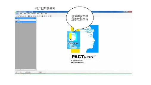
安装完成后,打开安装目录下的UTEPM.EXE文件,根据先前输入的安装路径,打开组态软件:
图2. 打开组态软件
3.将带硬件狗P+F专用通讯电缆与笔记本电脑和安全栅连接后,打开软件
Instrument data选项,选择Maintenace(operating data)选项,点击OK:
图3. 选择Maintenace(operating data)选项
4.在Instrument data选项下,选择Instrument选项栏下Load from instrument 读取安全栅内的组态信息:
图4. 读取安全栅内组态信息
5.修改安全栅内部组态信息与温度仪表设备一致,后点击Save to instrument 下装到安全栅即可(如:TI1395S更改内容有:探头类型K型、单位℃、上下量程等信息),也可以先选择一块同类型的安全栅读取其内部组态信息后,再将通讯线缆连接到需要组态的新安全栅后点击Save to instrument进行下装:
图5. 修改并下装安全栅组态信息。
---------------------------------------------------------------最新资料推荐------------------------------------------------------
P F安全栅组态步骤
P+F 安全栅(温度)组态步骤一、安装软件插入光盘,光盘自动运行出现下面的画面,共有 13 个安装项。
点击每一项右侧会有安装提示,根据说明安装自己需要的软件。
二、运行软件开始程序PACTWare 3.0 (下拉菜单)PACTWare
3.0,选择 DEVICEADD DEVICE,出现如下画面选择所要添加的设备类型,例如温度安全栅 KFD2-UT2-EX1 则选择 P2P RS232 FDT。
右键单击选择 ADD DEVICE,如下图,以下以 P2P RS232 FDT 设备为例进行说明。
右键单击 P2P RS232 FDT 属性,如下选择需要的通讯端口。
本机的 COM 端口要与这里选择的一致。
上面的 Flow comtrol 必须选择 Xon/Xoff项。
继续添加设备如下双击新添加的设备连接设备如下加载设备参数。
按照需求更改输入 input 属性按照需求更改输出output 属性,例如量程。
Characteristic 选项要选择 4-20mA NE43。
下装到设备即可当断开连接前不忘 disconnect。
1 / 1。