ASME支腿计算
- 格式:pdf
- 大小:185.49 KB
- 文档页数:10
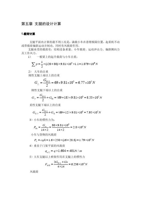
第五章 支腿的设计计算1.载荷计算支腿平面内计算的最不利工况是:满载小车在悬臂极限位置,起重机不动或带载荷偏斜运动并制动,同时有风载荷作用。
支腿承受的载荷有:结构设备重量、小车载荷、运动冲击力、偏斜侧向力及工作风力。
1) 一根梁上的起升载荷与小车自重:361(12080)9.8110 1.1 1.079102p N =⨯+⨯⨯⨯=⨯∑ 2) 大车的自重刚性支腿上端以上的自重35699.8110 6.77102G G N ==⨯⨯=⨯静总上刚性支腿下端以上的自重 3569189.81108.53102G G G N =+=+⨯⨯=⨯静总下刚()柔性支腿下端以上的自重 3569129.81107.95102G G G N =+=+⨯⨯=⨯静总柔下柔()3)小车的惯性力为:34809.8110 2.810142142xc Hx G P N ⨯⨯===⨯⨯⨯小车与货物的风载荷41.6250(1628.8) 1.7910w P cqA N ==⨯⨯+=⨯4)垂直于门架平面的风载荷1.604401/w q q N m =⨯=门5)大车支腿以上桥架作用在支腿上的惯性力42 6.23610414H G Gx F N +==⨯⨯静总惯风载荷42.5104Fw Pw N ⨯===⨯主(384+16+4)25046)作用与支腿架的风载荷和支腿自重惯性力:464/A q N m =刚536/A q N m =柔1043.8/H q N m =刚695.8/H q N m =柔 7) 偏斜运行侧向载荷 Ps小车满载跨中4s18.0910P N ==⨯ 小车满载极限位置5s2 1.06210P N =⨯2.支腿内力计算(1)门架平面的支腿内力计算柔性支腿与主梁铰接,因此门架平面按静定简图进行内力计算:○1满载小车位于臂端,c 点受弯矩11c M H h =32(23)LH P h k =⨯+∑21I hk I L=•12911140.70.30.7 1.095100.39.347107.69310mmy y I I I =+=⨯⨯+⨯⨯=⨯刚下刚上1142 3.78510x I I mm ==⨯0.1189k =653131.07910 4.4810214.5(20.11893)H N ⨯=⨯⨯=⨯⨯⨯⨯+561 4.481014.5 6.5010c M N m =⨯⨯=⨯•○2小车惯性和风载荷:4425()(2.810 1.7910)14.56.6510c A H WM H h P P h N m==+=⨯+⨯⨯=⨯•○3支腿风载荷 2221140114.5 4.21522c w M q h N m ==⨯⨯=•○4偏斜运行侧向力为Ps 引起内力51.06210s P N=⨯521 1.06210M SB N m ==⨯•B 1=1m5461.0621014.51.539910c l c sM M M Ph N m N m====⨯⨯•=⨯•(2)在支腿平面内的支腿内力在支腿平面内支腿与桥架连接相对为柔性连接,支腿与下横梁为刚性连接○1大车制动惯性力PH 和风载荷Pw 作用引起内力: 61() 1.26710H w M P P h N m =+=⨯•62121 1.26710M N B M N m =-=⨯•22() 3.958H w hN P P N B=+=○2作用于支腿平面的风载荷与支腿自重惯性力21222a H q q M h M +==刚性支腿2514641043.814.5 1.58102M N m +=⨯=⨯•柔性支腿 2512536695.814.5 1.295102M M N m +==⨯=⨯•3.支腿强度计算门架平面内,刚性支腿上端截面受到弯矩。

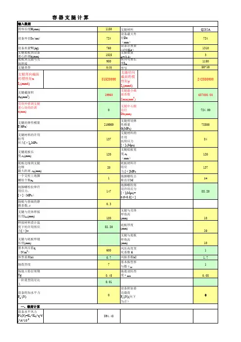
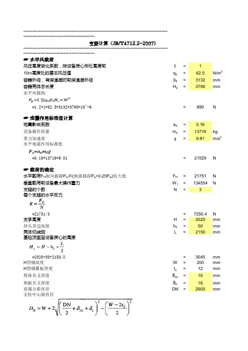
****************************************************************************************************************************************************************************************************************************************************☞ 水平风载荷风压高度变化系数,按设备质心所处高度取f i =110m 高度处的基本风压值q0=62.5容器外径,有保温层时取保温层外径D 0=3132容器壳体总长度H 0=3790水平风载荷:=1.2*1*62.5*3132*3790*10^-6=890☞ 地震作用标准值计算地震影响系数a e =0.16设备操作质量m 0=13716重力加速度g=9.81水平地震作用标准值 =0.16*13716*9.81=21529☞ 载荷的确定水平载荷F H 取风载荷P w 和(地震载荷P e +0.25P w )较大值F H =21751垂直载荷取设备最大操作重力W 1=134554支腿的个数N=3每个支腿的水平反力=21751/3=7250.4支承高度H =2020封头直边高度h 2=50壳体切线距L=2150基础顶面至设备质心的高度=2020-50+2150/2=3045H 型钢高度W =200H 型钢翼板厚度t 2=12筒体名义厚度δ2n =16垫板名义厚度δn =16容器公称直径DN=2900支柱中心圆直径=200+2*SQRT((2900/2+16+16)^2-((200-2*12)/2)^2)=3158.8单根支腿垂直反力(弯矩的拉伸侧)支腿计算(JB/T4712.2-2007)=4*21751*3045/(3*3158.8)-134553.96/3=-16894单根支腿垂直反力(弯矩的拉伸侧)=4*-21751*3045/(3*3158.8)-134553.96/3=-72808☞ 支腿稳定及强度计算H型钢宽度B=200H型钢高度H‘=200H型钢腹板厚度t1=8H型钢翼板厚度t2=12支腿材料的拉伸弹性模量E=206000支腿材料的屈服强度R eL=235.4设备重要度系数η=1单根支腿的轴向水平截面惯性矩I X-X=46104917单根支腿的径向水平截面惯性矩I Y-Y=16007509单根支腿的横截面面积A=6208假定支腿与壳体的链接为固接,支腿端部为自由端。
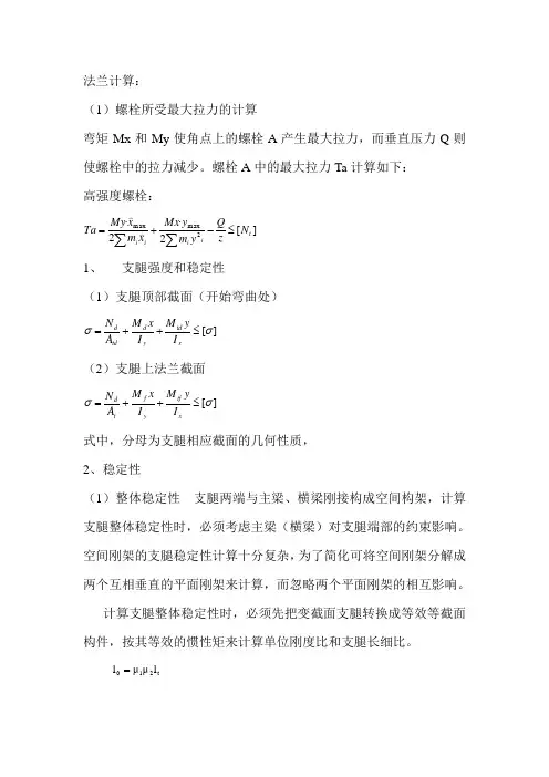
法兰计算:(1)螺栓所受最大拉力的计算弯矩Mx 和My 使角点上的螺栓A 产生最大拉力,而垂直压力Q 则使螺栓中的拉力减少。
螺栓A 中的最大拉力Ta 计算如下: 高强度螺栓:][2·2·2max max t i i i i N zQ y m y Mx x m x My Ta ≤-+=∑∑ 1、 支腿强度和稳定性(1)支腿顶部截面(开始弯曲处)][σσ≤++=xtd y d td d I y M I x M A N (2)支腿上法兰截面][σσ≤++=xtf y f t d I y M I x M A N 式中,分母为支腿相应截面的几何性质,2、稳定性(1)整体稳定性 支腿两端与主梁、横梁刚接构成空间构架,计算支腿整体稳定性时,必须考虑主梁(横梁)对支腿端部的约束影响。
空间刚架的支腿稳定性计算十分复杂,为了简化可将空间刚架分解成两个互相垂直的平面刚架来计算,而忽略两个平面刚架的相互影响。
计算支腿整体稳定性时,必须先把变截面支腿转换成等效等截面构件,按其等效的惯性矩来计算单位刚度比和支腿长细比。
t 210l μμl =支腿的长细表:rl 0=λ 支腿整体稳定性按右式计算:][σφσ≤++=xtd y d td d I y M I x M A N20吨小车计算:钢丝绳的选择: (1) 钢丝绳的最大拉力:根据起重机的额定起重量Q=20吨,查起重机手册选取滑轮组倍率m=4,起升机构缠绕如图:钢丝绳最大拉力:组ηm G Q S 2max += kg 式中Q ——额定起重量,Q=20*103kgG ——钓钩组重量,G=364kgm ——滑轮组倍率 m=4组η——滑轮组效率,组η=0.975根据公式得到Smax=2610kg(2)钢丝绳的选择所选择的钢丝绳破断拉力应满足下式;max S *n S 绳绳≥而∑=丝绳αS S *式中;S 绳——钢丝绳破断拉力 ΣS 丝——钢丝绳破断拉力总和。
α——折减系数,对于绳6X37+1的钢丝绳α=0.82n 绳——钢丝绳安全系数,对于中级工作制度,n 绳=5.5由公式可得ΣS 丝=17511kg查钢丝绳样本钢丝绳直径为17.5mm2、滑轮与卷筒的计算(1)滑轮和卷筒最小直径的确定为确保钢丝绳具有一定的安全使用寿命,滑轮和卷筒名义直径应满足下式绳ed D ≥0 式中 e ——系数,对于中级工作制度e=25所以D0≥437mm ,取直径为D0=500 mm(2)卷筒长度的计算L 双=2*(L 0+L 1+L 2)+L 光 t n D m H L *).*(0max 0+=π 式中;H max ——最大起升高度,H max=10mn ——钢丝绳安全系数, n=2t ——绳槽节距,t=d 绳+(2~4)=20mmL1——根据结构确定卷筒空余部分,取L1=60mmL 光——根据钢丝绳允许偏斜角确定,L 光=120mmL0——卷绕部分长度 L0=550mmL 双=1500mm(3)卷筒轴上扭矩 卷η卷0max D S m =式中η卷=0.98 所以m 卷=1332kg*m(4)卷筒转速0D mvn π=3、根据静功率选择电动机起升机构静功率按下式计算:06120)(ηv G Q N += kw X X X N 98.349.061203.9)36410320(=+=查电动机样本得功率为4、减速器的选择(1)传动比根据传动比i=30.4,电动机功率N=30千瓦,电动机转速n=720转/分,工作制度=25%,查减速机样本选择ZQ650-31.5输入功率N=29千瓦。
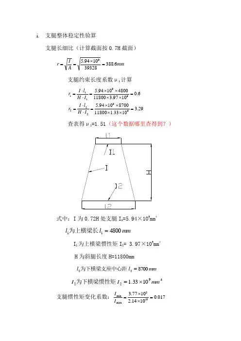
i. 支腿整体稳定性验算
支腿长细比(计算截面按0.7H 截面) mm A I r 6.38839328
1094.59
=⨯== 支腿约束长度系数μ1计算 29.31033.11180087001094.56.010
97.31180048001094.59922299111=⨯⨯⨯⨯=⋅⋅==⨯⨯⨯⨯=⋅⋅=I H l I r I H l I r
查表得μ1=1.51(这个数据哪里查得到?)
式中:I 为0.72H 处支腿I x =5.94×109mm 4
mm l l 480011=为上横梁长
I 1为上横梁惯性矩I 1= 3.97×109mm 4
H 为斜腿长度H=11800mm
mm l l 870022=为下横梁支座中心距
49221033.1mm I I ⨯=为下横梁惯性矩
支腿惯性矩变化系数:017.010
14.21077.3108max min =⨯⨯=I I
查表得7.12=μ(这个数据哪里查得到?)
支腿计算长度:
mm l l 30290118007.151.1210=⨯⨯=⨯⨯=μμ 支腿长细比:786
.388302900===r l λ 查表得稳定性系数743.0=ϕ
稳定性验算:(为保险起见,支腿0.72H 处弯矩按上部截面值) y
x y x y x v I h M I h M A P •+•+•=ϕσ =9
89861052.8630104.11094.55.451106.539328743.01065.0⨯⨯⨯+⨯⨯⨯⨯+⨯⨯ = 168.6Mpa
<[]σ=176Mpa
合格。
(注:素材和资料部分来自网络,供参考。
请预览后才下载,期待你的好评与关注!)。
![最新容器支腿计算公式(支腿计算主要用于立式容器的支腿受力及地脚螺栓计算)[表格]](https://uimg.taocdn.com/679ee3732f60ddccdb38a025.webp)
吊车支腿载荷计算公式引言。
吊车是一种用于起重和搬运重物的机械设备,它通常由起重机和支腿组成。
支腿是吊车的重要部件,它能够提供稳定的支撑和支持,以确保吊车在起重过程中不会发生倾斜或翻倒。
支腿的设计和计算是吊车安全运行的关键,其中载荷计算是支腿设计的重要一环。
支腿载荷计算公式的重要性。
支腿的主要功能是承受吊车在起重过程中产生的水平和垂直载荷,以保证吊车的稳定性和安全性。
支腿的设计必须考虑到各种不同的工况和工作环境,因此载荷计算公式的准确性和可靠性至关重要。
通过合理的载荷计算公式,可以有效地确定支腿的尺寸、材料和结构,从而保证吊车在各种工况下都能够安全、稳定地运行。
支腿载荷计算公式的基本原理。
支腿在起重过程中所承受的载荷主要包括静载荷和动载荷两部分。
静载荷是指吊车在静止状态下由于重力和外部荷载所产生的载荷,而动载荷则是指吊车在起重运动过程中由于惯性和动力所产生的载荷。
支腿的设计必须考虑到这两种载荷的影响,因此载荷计算公式需要综合考虑吊车的重量、起重物的重量、起重高度、起重速度等因素,以确定支腿在不同工况下的承载能力。
支腿载荷计算公式的推导。
支腿的载荷计算公式可以通过静力学和动力学的原理推导得出。
在静力学方面,可以利用平衡方程和杆件受力分析的方法,确定支腿在静止状态下的受力情况,从而得出支腿的静载荷计算公式。
在动力学方面,可以利用牛顿第二定律和动力学方程的方法,确定支腿在起重运动过程中的受力情况,从而得出支腿的动载荷计算公式。
通过综合考虑静力学和动力学的原理,可以得出支腿的综合载荷计算公式,从而为支腿的设计提供理论依据。
支腿载荷计算公式的应用。
支腿的载荷计算公式可以应用于吊车的设计、制造和使用过程中。
在吊车的设计阶段,可以根据支腿的载荷计算公式确定支腿的尺寸、材料和结构,从而满足吊车在各种工况下的承载要求。
在吊车的制造阶段,可以根据支腿的载荷计算公式进行支腿的加工、装配和测试,以确保支腿在实际使用中能够安全、稳定地运行。
泵车支腿压力计算公式在泵车工作中,支腿的稳定性是非常重要的。
支腿的稳定性直接影响到泵车的工作效率和安全性。
为了确保支腿的稳定性,需要对支腿的压力进行计算和控制。
在本文中,我们将介绍泵车支腿压力的计算公式,以及如何应用这个公式来确保支腿的稳定性。
泵车支腿压力计算公式可以通过以下公式来计算:支腿压力 = 载荷重量 / 支腿面积。
其中,载荷重量是指支腿所承受的重量,支腿面积是指支腿与地面接触的面积。
通过这个公式,我们可以得到支腿需要施加的压力,从而确保支腿的稳定性。
在实际应用中,我们需要考虑到一些额外的因素,如地面的硬度、支腿的材质和结构等。
这些因素都会影响支腿的稳定性,因此在计算支腿压力时需要进行综合考虑。
在进行支腿压力计算时,首先需要确定支腿的载荷重量。
这个重量通常由泵车的工作状态和所承载的物料来决定。
在确定了载荷重量之后,我们需要测量支腿与地面接触的面积,从而得到支腿面积。
在测量支腿面积时,需要考虑支腿与地面的接触情况,如是否有垫板、地面的坡度等因素。
通过以上步骤,我们可以得到支腿的压力。
在实际应用中,我们还需要考虑到地面的硬度和支腿的材质。
地面的硬度会影响支腿的稳定性,如果地面太软,支腿需要施加更大的压力来确保稳定。
支腿的材质和结构也会影响支腿的稳定性,因此在计算支腿压力时需要考虑这些因素。
除了计算支腿的压力之外,我们还需要对支腿的压力进行控制。
在实际应用中,通常会通过液压系统来控制支腿的压力。
通过调节液压系统的压力,可以实现对支腿压力的精确控制,从而确保支腿的稳定性。
总之,泵车支腿压力的计算公式为支腿压力 = 载荷重量 / 支腿面积。
在实际应用中,我们需要考虑到地面的硬度、支腿的材质和结构等因素,从而确保支腿的稳定性。
通过对支腿压力的计算和控制,可以提高泵车的工作效率和安全性。
ASME 设计计算公式
内压圆筒
1)环向应力(纵向接头)。
当厚度不超过内半径的1/2或p 不超过0.385SE 时: p SE PR t 6.0-= ( p SE PD t 2.12-=)或 t R SEt p 6.0+=
2)纵向应力(环向接头)。
当厚度不超过内半径的1/2或p 不超过1.25SE 时: p SE PR t 4.02+= ( p SE PD t 8.04-=)或 t D SEt p 4.02+=
球形壳体。
整个球形容器的壳体厚度不超过内半径的0.356R 或p 不超过0.665SE 时:
p SE PR t 2.02-= 或 t R SEt p 2.02+=
内压椭圆封头计算公式(长短轴2:1):
p SE PD t 2.02-= 或 t D SEt p 2.02+=
过渡段半径为0.17D 和球面半径为0.9D 的封头可近似看作2:1椭圆形封头。
蝶形封头。
过渡段半径等于球面部分内半径6%且球面部分内半径等于直边段外半径的蝶形封头,其所需厚度:
p SE PL t 1.0885.0-= 或 t L SEt p 1.0885.0+=
半球形封头(t ≤0.356L 或 p ≤0.665SE ):
p SE PL t 2.02-= 或 t L SEt p 2.02+=。
Design CalculationITEM NAME:xxxxxxxxxxxxxx DWG.NO.xxxxxxxxxxxxxx REVISION:xDate:Date:Date:PREPARED BY :REVIEWED BY :APPROVED BY :CONTENT1Loadings Considered3 2Vessel Technology Parameters4 3Design Data4 Required Thickness of Ellipsoidal Head 44 5Required Thickness of Shell5 6Opening Reinforcement Calculation5 7Required Nozzle Thickness Under Internal Pressure 9 8Impact Test Exemption Evaluation10 9 Post Weld Heat Treatment Exemption Evaluation11 10Check for Flange11 11 Check Inspection Openings11 12Standard Hydrostatic Test11 13Leg Design Calculation 12 14Lifting Lug Design Calculation 15xxxxxxxxxxxxxxAPPLIES ITEM YES (a) External pressure NO (b) Weight of the vesselYES (b) Weight of normal condition under operating condition YES (b) Weight of normal condition under test conditionYES (c) Superimposed static reactions from weight of attached equipment NO (d) The attachment of internalsNO (d) The attachment of vessel supports (saddles, lifting lugs) YES (e) Cyclic and dynamic reactions due to pressure NO (e) Cyclic and dynamic reactions due to thermal variations NO (e) Cyclic and dynamic reactions due to equipment mounted on a vessel NO (e) Cyclic and dynamic reactions due to mechanical loadings NO (f) Wind reactions NO (f) Snow reactions NO (f) Seismic reactionsNO (g) Impact reactions such as those due to fluid shock NO (h) Temperature gradients NO (h) Differential thermal expansions NO (i) Abnormal pressureNO (j) Test pressure and coincident static head acting during the testYES1. Loadings Considered◆ AS PER ASME CODE SECTION VIII , DIV.1,2015 UG-22 ◆ General Arrangement Drawing NO. (a) Internal pressure2. Vessel Technology ParametersItem Symbol Parameter Unit Remark Medium Compressed AirMAWP MAWP1MPaStatic Head of Liquids0.02MPa For hydrostatic test Design Pressure P 1MPaHydrostatic test#NAME?MPaWorking temperature0~90℃Design temperature Temp 93℃MDMT MDMT-20℃Shell Nominal thickness t3mmShell Inside Dimmeter D 400mmShell Material SA-240M 304Shell Allowable Stress at design Temperature S 137MPaShell Allowable Stress At Ambient Sa 138MPaJoint Efficiency of Shell,Shell to Head E1 0.85 ShellE20.85 Shell to Head Joint NDT SPOT RT : A1,B1,B2UW-52 Corrosion Allowance C0 mmTotal Volume0.20m3Vessel fully loading mass m270 kg3. Design Data3.1 Nozzle listLine Size Schedule tn O.D.Material UNS TYPE Sn Function N1DN100/NPS410S 3.05 114.3SA-312M TP304S30400sml.137Medium Inlet N2DN100/NPS410S 3.05114.3SA-312M TP304S30400sml.137Medium Outlet N3DN20/NPT3/440S 2.8726.7SA-312M TP304S30400sml.137Vent N4DN20/NPT3/440S 2.8726.7SA-312M TP304S30400sml.137Drain◆ The thickness of threading port N3~N4 is larger than schedules 10S, meet the requirement of SA-312M appendix.3.2Main MaterialPart MaterialShell&Head SA-240M 304 (II-D Metric p.86, ln.43)Pipe SA-312M TP304 (II-D Metric p.90, ln. 9)Flange SA-182M F304 (II-D Metric p. 86, ln. 32)4. Required Thickness of Ellipsoidal HeadDESCRIPTION Symbol DATA UnitDesign Pressure P 1MPaInside Diameter of Head Di400 mmHead Nominal thickness tn3mmHead Finished (Minimum) Thickness t 2.4mmAllowable Stress at design Temperature S 137MPaHead Ratio D/2h Ar 2Joint Effiency of Head E0.85◆ Minimum thickness per UG-16 (b)1.5mmt= 2.4L=360t/L=0.01≳0.002= 1.72mmt= 2.4it is customary to use a thicker plate to take care of possible thinning during the process of forming.So, The Min. thickness of head after forming is 2.4 mm.Conclusion:Satisfactory5. Required Thickness of Shell DESCRIPTION SymbolDATA Unit Design Pressure P 1MPa Radius of ShellR 200 mm Allowable Stress at design Temperature S 137MPaJoint Effiency of Shell0.85 Joint Effiency of Shell&HeadE20.851.5mmDesign thickness for internal pressure, Ⅷ-1 UG-27(c)(1), P=1< 0.385SE1=44.83= 1.73mm UG-16 (c): Min. plate thickness Undertolerance, 3mm 0.30mm 2.70mmP=1145.56=0.86mmt= 2.70Conclusion:Satisfactory6. Opening Reinforcement Calculationt 1=t min + Corrosion =◆ Design thickness due to internal pressure per Ⅷ-1 UG-32(d)t 2=PD/(2SE-0.2P)+ Corrosion ◆ The head internal pressure actual use design thickness(Req. min. thickness)mm > larger of t1, t2In order to ensure that a finished head is not less than the minimum thickness required,E 1◆ Minimum thickness per UG-16 (b) ,t 1=t min + Corrosion= t 2= PR/(SE 1-0.6P)+ Corrosion t n =t u = t=t n -t u =◆ Design thickness for internal pressure, Ⅷ-1 UG-27(c)(2)< 1.25SE2=t 3= PR/(2SE 2+0.4P)+ Corrosion ◆ The shell internal pressure actual use design thickness(Req. min. thickness) mm > larger of t1,t2,t3Opening in vessel not subject rapid fluctuation under the following condition:The nozzle N1, N2, do not conform to the condition mentioned above so reinforcement calculation is needed. Outside Projection ho 145mm Weld leg size between Nozzle and Pad/Shell Wo 3mm Inside Projection h 0mm Weld leg size, Inside Element to Shell Wi 0mm Shell thickness-corrosion t 2.70mm1.47mm 0.42mmtn 3.05mm Actual Outside Diameter Used in Calculation 114.3mm.= 1.47 mm= 0.42 mm UG-40, Limits of Reinforcement : [Internal Pressure]Parallel to Vessel Wall (Diameter Limit) Dl 216.40mm Parallel to Vessel Wall, opening length d 108.20mmWeld Strength Reduction Factor [fr1]:Weld Strength Reduction Factor [fr2]:= Sn/S = Sn/S = 1.00= 1.00Weld Strength Reduction Factor [fr3]:Weld Strength Reduction Factor [fr4]:= min( fr2, fr4 )= Sp/S = 1.00= 1.00Results of Nozzle Reinforcement Area Calculations:AREA AVAILABLE, A1 to A5 Symbol Without Rein Area Required Ar 158.65mm^2Area in Shell A1 133.49mm^2Area in Nozzle Wall A2 35.56mm^2Area in Inward Nozzle A3 0.00mm^2Area in Welds A41+A42+A43 9.00mm^2Area in Element A5 0.00mm^2TOTAL AREA AVAILABLE Atot 178.05mm^2The area available without a pad is sufficient.6.1 Checking exemption of reinforced opening UG-36(c)- (3)- (a)、(c) ---N3, N4◆ A finished opening not larger than 89mm diameter in vessel with a required minimum thickness of 10mm or less.◆ No two isolated unreinforced openings have their centers closer to each other than the sum of their diameter.The nozzle N3,N4 conform to the condition mentioned above so reinforcement for above openings is not needed.6.2 Opening Reinforcement Calculation for N1, N2(Insert Nozzle Without Pad, no Inside projection)Reqd thk per Ⅷ-1 UG-32(d) trReqd thk per UG-37(a)of Nozzle Wall, t rn trn Nozzle thickness(not including forming allowances)D0Required thickness per Ⅷ-1 UG-27(c)t r =PR/(SE-0.6P)+Corrosion Reqd thk per UG-37(a)of Nozzle Wall, t rn [Int. Press]t rn = (P*Ro)/(S*E+0.4*P) per Appendix 1-1 (a)(1)Area Required [A]:= ( d * tr*F + 2 * tn * tr*F * (1-fr1) ) UG-37(c)= 158.65mm^2Area Available in Shell [A1]:= max(d( E1*t - F*tr ) - 2 * tn( E1*t - F*tr ) * ( 1 - fr1 ), 2(t+tn)(E1t-Ftr)-2tn(E1t-Ftr)(1-fr1))= 133.49 mm^2Area Available in Nozzle Wall Projecting Outward [A2]: =min(5(tn-trn)fr2t,5(tn-trn)fr2tn)=35.56mm^2Area Available in Welds [A41 + A43]:= Wo^(2)*fr3+Wi^(2)*fr2= 9.00mm^23mm 2.1mmtc(actual) = 2.1mm UW-16 Weld Sizing Summary Weld description Required weld throat size (mm)Actual weld throat size (mm)Nozzle to shell fillet2.1 2.1Conclusion:SatisfactoryWeld strength calculations are not required as per UW-15(b) for this detail which conforms to Fig. UW-16.1, sketch (c).2.87mm 2.01mmtc(actual) = 2.1mm UW-16 Weld Sizing Summary Weld description Required weld throat size (mm)Actual weld throat size (mm)Nozzle to shell fillet2.01 2.1Conclusion:SatisfactoryWeld strength calculations are not required as per UW-15(b) for this detail which conforms to Fig. UW-16.1, sketch (c).6.4 FLANGE TO NOZZLE NECK WELDS6.4.1 Calculation for N1, N2As per Fig. UW-21, illustrations (1)Internal weld size:3.05mm 4mm > 3.05 mm OK6.3 UW-16(c) Weld Check for All nozzles 6.3.1 UW-16(c) Weld Check for N1&N2Fillet weld: t min = lesser of 19 mm or t n or t = tc(min) = lesser of 6 mm or 0.7*t min =6.3.2 UW-16(c) Weld Check for N3,N4Fillet weld: t min = lesser of 19 mm or t n or t = tc(min) = lesser of 6 mm or 0.7*t min =UW-21(b): ASME B16.5 slip-on flanges shall be welded to a nozzle neck using an internal and an external weld. t min =The lesser of tn or 6 mm=实际X(actual)=External weld size:= 4.27 mm 5mm > 4.27 mm OKX min =the lesser of 1.4tn or the thickness of the hub实际X(actual)=Schematic diagramAngle Radian α300.5236β60 1.0472γ200.3491SA-240M 30495.9MPa 67.13MPa0.7SA-240M 304137MPa 1.65Vessel fully loading mass,G:270KG 9.8140mm 25mm 25mm 8mm 14.14368.57N14.2Transverse loading2522.20N14.35044.39N14.414. Lifting Lug Design Calculation Per HG/T 21574-2008The material of lifting lug:Tensile stress in lifting lug [σL ]:Shear stress in lifting lug [τL ]:Joint efficiency for fillet weld:The material of head:Allowable stress in head:Composite influence factor,K:Gravitational acceleration,g,Type in:L-The distance between the centre of lifting lugs to head,R-The radius of lifting lug,D-The diameter of eye for lifting lug,S-The thickness of lifting lug,Vertical loadingComputational formula :Fv=G×g×1.65F V =Computational formula :F H = Fv •tanαF H =Lifting rope direction loadingComputational formula:F L =Fv/CosαF L =Bending moment for warp directionM=100887.87N*mm14.525.22MPaOK14.625.22MPaOK14.7A=643.806.79MPa3.92MPa12.09MPa20.44MPaσ=67.13MPaConclusion:OKComputational formula:M= F H •LThe max tensile stress for the lifting lug in the Lifting rope directionComputational formula:σL =F L /[(2R-D)*S]σL =σL <[σL ]The max shearing stress for the lifting lug in the Lifting rope directionComputational formula :σL =τLτL =σL =σL <[τL ]Check fillet weld for lifting lugThe area of fillet weld is conservative:Computational formula:A=2*(L*tanγ+R)*Smm 2The tensile stress for fillet weld:Computational formula:σa =F V /Aσa =The shearing stress for fillet weld:Computational formula:τa =F H /Aτa =Bending stress for fillet weld:Computational formula:σab =6M/(S*(2*(L*tanγ+R ))2)σab =Combined stress:Computational formula:σab =((σa +σab )2+4τa 2)1/2σab =The allowable stress of fillet weld:Computational formula:σ=0.7*[σL ]Lug strength calculation:σab <σ。