2020版跟踪仪配件产品单页
- 格式:pdf
- 大小:2.65 MB
- 文档页数:24
一、美国API公司简介美国自动精密工程公司(A utomated P recision I nc.)由刘锦潮博士(Dr. Kam u)创建于1987年。
公司自成立以来始终致力于机械制造领域精密测量仪器和高性能传感器的研制和生产,产品已广泛应用于美国及世界各国的先进制造领域。
在与美国联邦政府、美国国家标准局(NIST)、国家制造科学中心、密歇根大学、马里兰大学、北卡罗莱纳大学、康涅狄格大学等的项目合作中,API公司都是积极参与者和关键技术伙伴。
API公司迄今为止所取得的成就使其在国际精密测量领域享有很高的声誉。
刘锦潮博士于八十年代初率先开展激光跟踪测量技术的研究,持有激光测量系统多项专利,是全世界公认的激光跟踪技术发明者。
API公司不仅推出了国际上第一台商业化激光跟踪仪(即瑞士莱卡激光跟踪仪)。
而且是目前世界上唯一能生产六维激光跟踪仪的厂家。
API研制的绝对测距(ADM)技术早在1996年就在美国宇航(NASA)和美国海军(NAVY)工程中得到了成功应用。
目前,API激光跟踪仪已经被广泛应用到了航空、航天、汽车制造、造船、铁路机车、机床、石油、电子等行业。
美国国家标准局(NIST)、中国国家计量科学研究院、美国宇航局、Boeing、Airbus、洛克希德马丁公司、英国航空公司、法国雪铁龙公司、通用汽车公司、日产、标致、雷诺、雪铁龙等都已成为API公司的忠实用户。
中国国家计量科学研究院(NIM)作为中国计量行业的最高权威单位与API的合作更体现了强强联合的特点。
API激光跟踪仪的客户清单及在航空及船舶行业的使用状况详见附后。
为更好地服务于中国客户,API公司于2004年初在上海成立了上海爱佩仪自动精密仪器科技有限公司,作为中国用户的技术服务中心。
API上海公司的工程技术人员均为本科或硕士学历,并定期在美国总部接受专业的技术培训,上海公司可以提供设备的操作培训、维修保养和设备标定,同时面向中国客户提供API产品的零配件供应,以最大地方便客户,为客户提供最优质的服务。
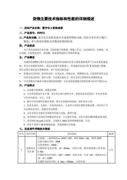
货物主要技术指标和性能的详细描述一、投标产品名称:数字化X射线系统二、产品型号:DTP571三、产品的功能:数字化X射线系统具有透视和摄影功能,供医疗单位用于胸片、腹部、骨与软组织摄影及胃肠造影辅助检查。
四、产品组成本产品由高频高压发生器、X射线数字探测器、图像工作站、动态遥控床、电源柜、高压电缆、X射线管组件、滤线栅、限束器和遥控台等部件组成。
五、产品概述安健科技DTP571数字化X射线系统利用高频高压发生器使X射线管产生高质量的X射线,穿过人体被检查部位,到达动态数字探测器上,形成被检查部位的X射线数字图像,然后送到计算机进行图像处理。
本产品的功能包括:➢机械运动及控制:采用电动床,床身运动、床面运动、探测器运动、X射线管组件运动均采用电动控制,操作方便,可以满足临床立、卧位及其它特殊体位的摄影要求。
➢可实现覆盖全胸和全腹范围的连续摄影,且由连续拍摄模式转静态模式时间不超过1s。
六、产品特点1、动态数字探测器,成像更清晰。
2、大功率高频高压发生器,高压发生器与球管分开,使射线品质更优异,外形更美观,可长时间使用,安全、可靠。
3、操作台采用图形化操作界面,数字化智能控制系统,操作简单方便。
4、设有多部位、多体位、多体型的成人、儿童等人体特征摄影参数设置,同时用户可自由修改及存贮,使操作更为简便。
5、具有多重自动保护及故障代码提示功能,维修方便。
6、采用国际专业的医学图像处理技术,中文操作界面,具有完善的DR图像处理功能。
7、采用国际Dicom3.0标准,方便联入PACS系统和图像传输、打印。
8、采用千兆网与DR探测器连接,采集图像安全快捷。
七、设备部件详细技术指标。
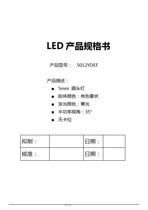
LED产品规格书产品型号:5012YDEF产品描述:■5mm 圆头灯■胶体颜色:有色雾状■发光颜色:黄光■半功率视角:35°■无卡位外形图:备注:1.所有尺寸单位为mm,如无特殊标明误差范围为±0.25mm。
2.胶体沿支架延伸不超过1.5mm。
3.多胶不超过0.5mm。
最大限度性能参数(Ta=25℃)产品光电特性(Ta=25℃)备注:1.发光强度的测量公差为±15%2.电压的测量公差为±0.05V3.主波长测量公差为±1nm使用说明1.LED贮存条件:温度10℃~26℃,湿度40%~65%,包装袋密封保存。
2.接触LED检查时需戴手套或手指套,工作台面也要接地,包装袋开口后及时封口,防止脚位氧化。
3.插件,这一过程主要是静电的防护:A:生产前检点机台设备接地线是否正常。
B:检查人员静电环是否正常,查静电环的金属是否与人的皮肤接触紧密。
C:在插件时最好要求作业员戴好静电手套或静电手指套。
D:作业台面要求铺好静电胶布,胶布之间应互相连接接地。
E:开封后,最好在24小时内用完,否则可能会引起灯脚氧化生锈。
4.焊接两只脚LED有四种方法:手动焊接,自动点焊,过锡炉焊接,波峰炉焊接:A:手动焊接:一般电铬铁温度设定在315℃左右,焊接时间不超过5秒,最好在3秒,焊接次数不要超过三次。
电铬铁温度选择一般是根据锡丝成份而定,并不是不变的。
B:自动点焊:此焊锡一般按常规设定,焊锡温度一般按锡丝成份而设定。
设定时间为3秒。
C:锡炉焊接:现阶段在中国比较普遍,在使用前一般要点检锡炉温度是否符合所设定的温度最高不超过235℃±5℃,浸锡时间不超过5秒,点检锡液温度,选择合适的助焊剂,要经常清洁锡液面。
D:波峰焊接:是目前比较先进焊接,这个对选用助焊剂比较重要,不同型号的助焊剂,对焊点光洁度不同,预热时间长短对焊接品质也有关系,经常点检锡面,锡液要定时更换,温度要根据锡条的成份调节,但最高不要超过260℃±5℃,最长时间不要超过5秒。
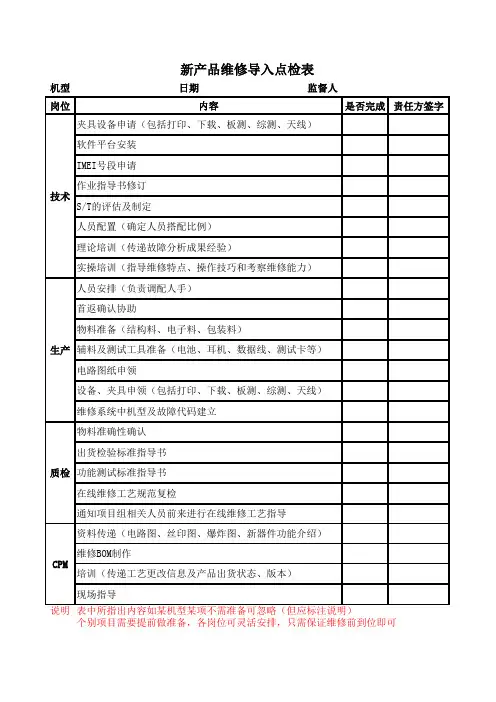
机型
日期监督人岗位是否完成责任方签字说明软件平台安装
IMEI号段申请
通知项目组相关人员前来进行在线维修工艺指导
物料准确性确认
新产品维修导入点检表
S/T的评估及制定
人员安排(负责调配人手)
生产辅料及测试工具准备(电池、耳机、数据线、测试卡等)
维修系统中机型及故障代码建立
首返确认协助
电路图纸申领
个别项目需要提前做准备,各岗位可灵活安排,只需保证维修前到位即可表中所指出内容如某机型某项不需准备可忽略(但应标注说明)
理论培训(传递故障分析成果经验)
实操培训(指导维修特点、操作技巧和考察维修能力)
资料传递(电路图、丝印图、爆炸图、新器件功能介绍)
维修BOM制作
培训(传递工艺更改信息及产品出货状态、版本)
物料准备(结构料、电子料、包装料)
设备、夹具申领(包括打印、下载、板测、综测、天线)
出货检验标准指导书
CPM 夹具设备申请(包括打印、下载、板测、综测、天线)
技术
作业指导书修订
人员配置(确定人员搭配比例)
内容
在线维修工艺规范复检
质检功能测试标准指导书
现场指导。
Micro FocusThe Lawn22-30 Old Bath RoadNewbury, Berkshire RG14 1QNUK© Copyright 1992-2019 Micro Focus 或其关联公司。
MICRO FOCUS、Micro Focus 徽标和 Silk Test 是 Micro Focus 或其关联公司的商标或注册商标。
All other marks are the property of their respective owners.2019-04-30ii内容关键字驱动的测试 (4)测试自动概述 (4)关键字驱动的测试的优势 (4)关键字 (5)将 Silk T est 与 Silk Central 相集成 (6)将关键字库上载到 Silk Central (7)通过命令行将关键字库上载到 Silk Central (9)通过自动化手动测试创建关键字驱动的测试 (10)在 Silk Central 中创建关键字驱动的测试 (10)在 Silk Central 内的测试中管理关键字 (10)Silk Test 推荐哪些关键字? (12)使用关键字的参数 (13)示例:带参数的关键字 (13)在 Silk T est 中创建关键字驱动的测试 (15)在 Silk T est 中录制关键字驱动的测试 (15)在 Silk T est 中为关键字驱动的测试设置基态。
(16)在 Silk T est 中实施关键字 (16)在 Silk T est 中实施 Silk Central 关键字 (17)在 Silk T est 中录制关键字 (18)编辑关键字驱动的测试 (18)将关键字组合为关键字序列 (19)从 Eclipse 回放关键字驱动的测试 (19)从 Silk Central 回放 Silk T est 测试 (20)通过命令行回放关键字驱动的测试 (21)用 Apache Ant 回放关键字驱动的测试 (22)使用特定变量回放关键字驱动的测试 (23)分组关键字 (24)内容 | 3关键字驱动的测试关键字驱动的测试是一种软件测试方法,它将测试设计与测试开发分离开来,因此允许其他专业小组参与测试自动化流程,例如业务分析师。
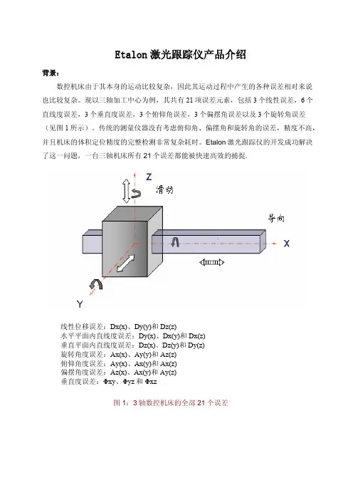
Etalon激光跟踪仪产品介绍背景:数控机床由于其本身的运动比较复杂,因此其运动过程中产生的各种误差相对来说也比较复杂。
现以三轴加工中心为例,其共有21项误差元素,包括3个线性误差,6个直线度误差,3个垂直度误差,3个俯仰角误差,3个偏摆角误差以及3个旋转角误差(见图1所示)。
传统的测量仪器没有考虑俯仰角、偏摆角和旋转角的误差,精度不高,并且机床的体积定位精度的完整检测非常复杂耗时。
Etalon激光跟踪仪的开发成功解决了这一问题,一台三轴机床所有21个误差都能被快速高效的捕捉.线性位移误差:Dx(x)、Dy(y)和Dz(z)水平平面内直线度误差:Dy(x)、Dx(y)和Dx(z)垂直平面内直线度误差:Dz(x)、Dz(y)和Dy(z)旋转角度误差:Ax(x)、Ay(y)和Az(z)俯仰角度误差:Ay(x)、Ax(y)和Ax(z)偏摆角度误差:Az(x)、Ax(y)和Ay(z)垂直度误差:Φxy、Φyz和Φxz图1:3轴数控机床的全部21个误差测量原理:Etalon激光跟踪仪与传统激光干涉仪测量原理最大不同在于,它采用多步法体积定位测量方法对所有21个误差进行测量和捕捉。
按国际标准化组织定义,沿体对角线测得的位移误差是机床21项误差的综合反映,我们可以将沿体对角线方向测得的位移误差看成三个运动轴分别运动时产生的位置误差在体对角线方向的投影,沿每个轴的位移误差有三项,沿X轴的误差为:Dx(x)、Dy(x)、Dz(x),沿Y和Z分别为:Dx(y)、Dy(y)、Dz(y)、Dx(z)、Dy(z)、Dz(z)(如图1所示)。
上述9项位置误差中实际上包含了三个轴运动时产生的所有21项误差(线性位移误差、直线度误差、转角误差、垂直度误差,甚至其它一些非刚体运动误差),因此9项位置误差反映了机床的空间位置精度。
从误差补偿的角度看,对于具有空间位置误差补偿功能的数控系统来说,只要补偿该9项位置误差就相当于补偿了机床的所有几何误差元素对机床位置精度的影响,如补偿X轴的运动误差时,Dx(x)由X轴补偿,Dy(x)、Dz(x) 可分别通过Y、Z轴补偿,因此只要将九项位置误差数据经处理按补偿格式传入数控系统即可实现机床的几何误差补偿,来提高机床体积定位精度。
74F aro Laser TrackersFaro Vantage / Faro Ion / Faro Xi This guide applies to the setup of the Faro X, Xi, Ion and Vantage (in-cluding Vantage S /E , Vantage S6/E6 models). Hardware SetupSet up the unit following the manufacturer’s directions. Connect the temperature probe and ensure that it is well clear of any external heat sources (such as the heat fan on the back of the power supply). Ensure that the instrument is powered on and that an SMR is in the home position. Software SetupFaro trackers are networked TCP/IP connected devices and should be connected either to a wireless network or directly to a computer with an Ethernet crossover cable. Set your computer’s Local Network connection to be compatible with that of the Faro tracker. Faro trackers are shipped with a standard wired IP address of 128.128.128.100 (subnet 255.255.255.0). Wireless connections default to 169.254.4.115. Download the latest java drive from: http://www.kinematics.com/ftp/SA/Install/Driver Downloads/Laser Trackers/Faro/. Extract the fi les to the C:\ drive. This should create a directorystructure with the Faro Java fi les contained in C:\FaroJRE.Your JRE fi les must match your version of SA...■Versions 2017.02.09 and older, use the Faro JRE v4.3■Versions 2017.02.09 to 2018.07.11, use the Faro JRE v5.0.0.1■Versions 2018.12.07 to 2019.11.21, use the Faro JRE v5.1.3.1■Version 2020.04.09, use the Faro JRE v5.1.7.3■Version 2020.07.20 and 2020.12.01 use the Faro JRE v5.1.8.3■Version 2021.01 and newer use the Faro JRE v5.1.9.4 (requiredto support the 6D probe2)If you plan to use the video (overview) camera, you must also get the‘Faro Tracker Camera fi les.zip’ fi le (version matching that of the JREFiles). Unzip the fi le and follow the instructions contained in ReadMeFaro Camera.txt. Note that cameras are wireless. If your camerahas the default IP address, you can set your PC’s wireless connection’saddress to 129.129.0.1.Starting the Interface1. Select Instrument > Add and choose the appropriate Faro track-er from the Add Instrument to SA dialog (Figure 3-64).Figure 3-64. Adding a Faro tracker752. Run Interface Module without connecting (Instrument > Run In-terface Mode) and choose Laser Trackers.3. Within the Connect to Spatial Analyzer dialog, Se-lect the instrument station (computer name, job name,Collection::Instrument Name: Serial Number) you wish to con-nect your instrument to from the network list and press OK.4. This will bring up the Faro Connection dialog (Figure 3-65).Figure 3-65. T he Faro Connectiondialog5. Enter the tracker’s IP address (if diff erent than the default) anduse the Ping button to test the connection if needed.Once satisfi ed, click OK. The next time you connect this instrument tothe instrument, you can just select Run Interface and Connect. This willutilize the last saved settings and automatically connect the instru-ment.Notes on the connection process:■The fi rst 7 digits of the tracker serial number can also be usedto fi nd the tracker. When you use this method it will search forboth a wired and wireless connection.■To connect Wireless, be sure to connect your computer to thetrackers wireless signal and use either the serial number or thewireless IP address which will something like 169.254.1.1 (notthe wired default).■If you have any trouble be sure to check your windows fi rewall.Exceptions need to be made for both the Spatial Analyzer andSA Laser Tracker applications.The interface is now connected and ready for use. Please refer to theMeasurements chapter of the manual for more details on the tracker76interface and instrument settings options.Faro Specifi c SettingsDistance ModeBeam rest can be manually overridden as needed. Choose between:■ADM Only. This mode restricts beam tracking operations toADM only.■IFM Only. This mode restricts beam tracking operation to IFMonly which requires a homing procedure each time the beamis broken.■IFM Set by ADM. Faro’s default mode which is a hybrid modethat provides accurate tracking using IFM and easy beam re-capture using ADM modes.External Trigger Settings■External Trigger Settings. The external trigger will apply toANY measurement profi le which has either a spatial or tempo-ral scan as it’s Acquisition.When “External” is set (for the Measurement Start Trigger in the FaroTracker Settings), points will be taken when the trigger is pulsed. Theonly requirements is that a profi le must be started for the externaltrigger to be recognized which as an Acquisition mode of either spa-tial or temporal scan. The advantage of this design is that no adjust-ments to the measurement profi le need to be made, and any profi lewill work (Figure 3-66).■The trigger cable must be connected to the “Up” port on thetracker controller.■0 Volts on the trigger port implies take data and send the datain continuous mode (where as 5Volts indicates stop). So bydefault the external trigger is set to on and sending data andmust be powered to stop sending data. This means that if thereis no external trigger, the measurement will simply begin at themaximum temporal rate of the trackers.77Figure 3-66. F aro tracker settingsincluding external trigger settingsSearch SettingsFaro’s video camera is used is used for refl ector acquisition and pro-vides a couple of optional modes:■Camera Search Enabled. This option enables camera search.Disabling this option is used to limit target search to a beamspiral search only.■Find Me Enabled. This is similar to the “Gesture Recognition”setting and allows the tracker to snap to the moving target.■Active Seek Radius. Active Seek can be set from main window(formerly “Smart Find”) dialog if supported. The Active Seek Ra-dius can be set to limit the search zone relative to the currentbeam position considered by the camera.Spatial Scan Data Buff eringData buff ering was added to ensure that SA keep up with data deliv-ered form the instrument. With a very tight scan increment this canbe quite fast (~100Hz).■Enable Faro Data Buff ering. Provides a switch to enable ordisable data buff er. If unchecked, behavior is unchanged fromprevious versions■ Buff er Size. Default is 0.2. At 0.2, for a spatial increment of0.01” (2.54 mm), the buff er would be 0.2/0.01 = 20 pts. Anotherway to look at this is the Buff er Size means the number of inch-es worth of data that will get buff ered. So at a value of 1.0 anda spatial increment of 0.01”, the buff er size would be 1.0/0.01 =100 pts, and with a point every 0.01”, 100 of them takes up 1.0inch.78■Do not buff er if increment is >= . This allows you to set a max-imum increment for which buff ering will occur. The defaultvalue is 0.1, meaning that when you set a spatial increment of0.1” (2.54 mm) or higher, no buff ering will occur.Its important to know that this buff ering happens on the Faro side,the interface will not receive any data until the buff er is fi lled. So forexample, you cannot set a scan whose increment would result in acalculated buff er size of 100 points, and yet set a profi le to stop at 20points because it will not send data at all until 100 points have beenrecorded.Specialty TargetsWindowed SMR Confi gurationWindowed SMR’s have an additional ADM off set, due to their glassfront, which needs to be accounted for. This is done by building a tar-get based upon the correct refl ector defi nition (see “Targets and Ret-ros” on page 19). Care should be taken to always use a target that isrepresentative of the actual refl ector being used or an error equal tothe ADM constant may be seen in your measurements.As stated in the Faro accessories manual, proper use of the windowedSMR requires sending it home when the target type is set correctly,otherwise an error will occur. This ensures the correct ADM off set isused. Additionally, when running startup checks or CompIT with thewindowed SMR, you should be sure to send the tracker home after-wards, as these routines assume 1.5” standard SMR is being used. Anadditional homing operation should be performed to update the tar-get defi nition.Faro 6D ProbeFaro’s 6D probe can be used within SA, using the Vantage S6 and Vanta-ge E6 trackers. No additional driver installation is required. Compatibletrackers will include a 6Probe defi nition.■The Faro 6Probe version 2 with exchangeable tips requires SAversion 2021.01 or later.The 6probe target detection is automatic but an initial connectionand activation process must be performed each time the 6D Probe ispowered on, and would go as follows:1. Connect to the Tracker2. Power on the 6D Probe Unit and catch the beam.3. Press any button on the probe and wait (approx. 10-20 sec.)for the probe’s “happy” beep and blue LED. If you have troublegetting the 6Probe to activate, try moving it farther from thetracker.794. After the fi rst successfully pairing of the 6Probe and tracker,you’ll be asked if you want to pop the Probe Management UIto set the active probe tip. Hit “Yes”, and select a tip that isValid, or Calibrate at least one probe tip, and select it.The probe is auto-detected once a probe tip is activated. When you lock back on to a 3D probe, the last used 3D probe will be set ac-tive for you. The pairing process will not be necessary again until the probe is powered down.The follow status indicator lights may be displayed:■No Lights Flashing. Press a probe button to begin the initial connection process.■Flashing Blue Lights. A connection to the probe is being made... wait for completion.■Flashing Red Lights. Connection attempt failed. Press a but-ton to begin again.■Flashing Green Lights. Success full connection has been es-tablished, waiting for tip selection. The Probe Management UI will open automatically to allow tip selection.■Solid Green Lights. Ready to Measure.Once confi gured, the probe is auto-detected and will be set simply by catching the beam. When you lock back on to a standard 3D refl ector, the last used refl ector (such as a 1.5” ball) will be set as active.Tip selection and calibration is performed within the Faro utility win-dow that can be displayed directly from the Home Button in the inter-face which will read Manage Tips when a 6probe is active (Figure 3-67). Also note that the name and diameter of the active probe defi nitions is displayed on the Measure button.Figure 3-67. T ip Selection control from the “Home” button8081This utility is also accessible as a target defi nition within the Refl ec-tors and Targets database, where the 6Probe target functions as a but-ton and provides access through a left click to Faro’s Probe Manage-ment utility (Figure 3-68).Faro’s Probe Management utility provides:■Ability to select directly for a list of defi ned probe tips. The 6Probe version 2 will recognize tips automatically when theyare connected, but changes to the calibration or initial setup is still performed in this dialog.■With the addition of the auto-detect tips this is typically not necessary but it is possible to defi ne multiple tips for a holder.■Probe Compensation options■Probe Check options Figure 3-68. F aro’s M anagement U Ior tip selection and compensation Tool.Note that undefi ned tips will have an initial off set of -1 meter. To program the 6Probe’s buttons, just click on the “gear” icon (),and then on the Faro button (Figure 3-69).Figure 3-69. 6D Probe buttons canbe confi gured as needed through thegeneral setting.When set up for a given work fl ow, such as using the inspection tasklist, these buttons can be used to work for long periods without go-ing back to the computer. In addition, the 6Probe can be used as aremote even when using and SMR.A set of standard 6D measurement profi les will also be available withthe 6D Probe (Figure 3-70).Figure 3-70. S tandard Set of 6D Measurement ProfilesThese provide a starting point for custom measurement profi le de-velopment. 6D measurements send frame’s to SA to graphically de-fi ne position and orientation, which can be used in combination withregular point measurements (which also do save the probing infor-mation in the measurement details). For more information on defi n-ing measurement profi les (see “Measurement Profi les” on page 25).Running the Tracker Interface SeparatelyOne of the unique features about SA’s architecture is that the instru-82ment interface can be run separately from SA. This provides a meansto run multiple trackers independently on diff erent machines whileconnect to a single SA for data storage. Doing so also provides theability to separate the persistence fi les for individual trackers, as thepersistence fi le will be saved in the directory as where the tracker in-terface is launched, as opposed to the C:\Analyzer Data\Persistencefolder.In order to run the SA Laser Tracker process separately some addition-al support fi les are required. These include the following fi les (Figure3-71):the SA Laser Tracker process indepen-dently from SA.83。
组件跟踪卡组件跟踪卡
镜检日期 月 日喷丝板号镜检日期 月 日喷丝板号
镜 检 者喷丝板规格镜 检 者喷丝板规格
组装时间 月 日备 注组装时间 月 日备 注
组 装 者组 装 者
预热时间 月 日 时 分 预热时间 月 日 时 分 预热者 预热缸预热者 预热缸
装上时间 月 日 时 分 装上时间 月 日 时 分 装 上 者 装上部位装 上 者 装上部位
班 别班 别
拆卸时间 月 日 时 分 拆卸时间 月 日 时 分 拆 卸 者班 别拆 卸 者班 别
拆卸原因拆卸原因
组件跟踪卡组件跟踪卡
镜检日期 月 日喷丝板号镜检日期 月 日喷丝板号
镜 检 者喷丝板规格镜 检 者喷丝板规格
组装时间 月 日备 注组装时间 月 日备 注
组 装 者组 装 者
预热时间 月 日 时 分 预热时间 月 日 时 分 预热者 预热缸预热者 预热缸
装上时间 月 日 时 分 装上时间 月 日 时 分 装 上 者 装上部位装 上 者 装上部位
班 别班 别
拆卸时间 月 日 时 分 拆卸时间 月 日 时 分 拆 卸 者班 别拆 卸 者班 别
拆卸原因拆卸原因。
定性检测体外诊断试剂(盒)产品技术审评规范(2012版)根据《医疗器械注册管理办法》(国家食品药品监督管理局令第16号)的要求并结合定性检测体外诊断试剂(盒)产品的特点,为规范定性检测体外诊断试剂(盒)(以下简称试剂(盒)产品的技术审评工作,特制定本规范。
一、适用范围本规范适用于依据《体外诊断试剂注册管理办法》(试行)管理类别为Ⅱ类的、在医学实验室进行定性检测所使用的体外诊断试剂(盒),其中所述“定性”是指只给出阴性或阳性(有反应或无反应、是或非、有或无、正常或异常)两种可能的结果。
定量以及半定量检测试剂(盒)不适用于本规范,已有中华人民共和国国家标准和行业标准的产品不适用于本规范。
二、技术审查要点(一)试剂(盒)命名的原则试剂(盒)名称由三部分组成。
第一部分:被分析物的名称;第二部分:用途;如检测试剂盒、检测试纸;第三部分:方法或原理,如酶联免疫吸附试验法、胶体金免疫层析法等。
例:肌钙蛋白I检测试纸(胶体金免疫层析法)、抗角蛋白抗体检测试剂盒(间接免疫荧光法)。
(二)试剂(盒)的组成试剂(盒)的组成形式:如单试剂,双试剂,多试剂;试纸;微孔板等。
(三)工作原理试剂(盒)通过各自不同的反应原理,最终通过仪器检测或肉眼观测,对被分析物做出是或不是、有或无、阳性或阴性、有反应或无反应、检出或未检出的结果判定。
(四)产品适用的相关标准试剂(盒)适用以下相关标准:1.GB/T 191 包装储运图示标志;2.YY/T 0316 医疗器械风险管理对医疗器械的应用;3.YY 0466 医疗器械用于医疗器械标签、标记和提供信息的符号。
注:以上标准适用最新版本。
(五)产品的预期用途试剂(盒)的预期用途为对临床样本中被分析物的定性检测。
(六)产品的主要技术指标1. 外观目测检查,符合生产企业规定的正常外观要求(一般要求试剂无杂质,外包装完整无破损;标签清晰可辨)。
2. 净含量(适用时)用通用量具测量,液体试剂的净含量应不少于标示值。