液动执行器规格书
- 格式:doc
- 大小:701.50 KB
- 文档页数:7
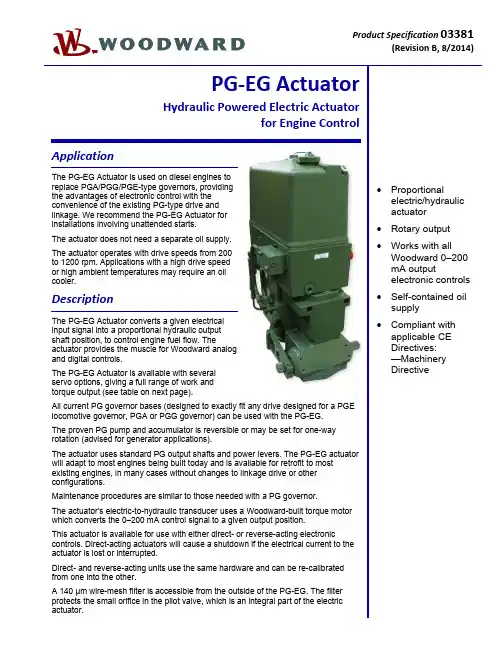
Product Specification 03381(RevisionB, 8/2014)PG‐EG ActuatorHydraulic Powered Electric Actuatorfor Engine ControlApplicationThe PG-EG Actuator is used on diesel engines toreplace PGA/PGG/PGE-type governors, providingthe advantages of electronic control with theconvenience of the existing PG-type drive andlinkage. We recommend the PG-EG Actuator forinstallations involving unattended starts.The actuator does not need a separate oil supply.The actuator operates with drive speeds from 200to 1200 rpm. Applications with a high drive speedor high ambient temperatures may require an oilcooler.DescriptionThe PG-EG Actuator converts a given electricalinput signal into a proportional hydraulic outputshaft position, to control engine fuel flow. Theactuator provides the muscle for Woodward analogand digital controls.The PG-EG Actuator is available with severalservo options, giving a full range of work andtorque output (see table on next page).All current PG governor bases (designed to exactly fit any drive designed for a PGElocomotive governor, PGA or PGG governor) can be used with the PG-EG.The proven PG pump and accumulator is reversible or may be set for one-wayrotation (advised for generator applications).The actuator uses standard PG output shafts and power levers. The PG-EG actuatorwill adapt to most engines being built today and is available for retrofit to mostexisting engines, in many cases without changes to linkage drive or otherconfigurations.Maintenance procedures are similar to those needed with a PG governor.The actuator's electric-to-hydraulic transducer uses a Woodward-built torque motorwhich converts the 0–200 mA control signal to a given output position.This actuator is available for use with either direct- or reverse-acting electroniccontrols. Direct-acting actuators will cause a shutdown if the electrical current to theactuator is lost or interrupted.Direct- and reverse-acting units use the same hardware and can be re-calibratedfrom one into the other.A 140 μm wire-mesh filter is accessible from the outside of the PG-EG. The filterprotects the small orifice in the pilot valve, which is an integral part of the electricactuator.∙ Proportionalelectric/hydraulicactuator∙ Rotary output∙Works with allWoodward 0–200mA outputelectronic controls∙ Self-contained oilsupply∙ Compliant withapplicable CEDirectives:—MachineryDirectiveSpecificationsControl QualitiesHysteresis Within 3% of maximum travel when measured over full travel. Within 0.5% ofmaximum travel when measured over 4% of full travel at 0.1 Hz.Temperature Drift Nominally ±1 degree per 38 °C (100 °F)Time Constant 65 to 85 ms for ±50 mA step with 1379 kPa (200 psi) actuator oil pressure and80 SUS viscosity oilLinearity Within 2.5% of full travelType 12 29 58 200 300 500Sump Capacity 1.4 liters1.5 qt US1.4 liters1.5 qt US1.4 liters1.5 qt US6.2 liters6.5 qt US6.2 liters6.5 qt US6.6 liters7.0 qt USMaximum Work Output16 J12 ft-lb39 J29 ft-lb79 J58 ft-lb237 J175 ft-lb422 J311 ft-lb648 J478 ft-lbRotary Travel 30° 30° 30° 42° 42° 42° Serrated OutputShaft Dimension0.750-48 1.000-48 1.000-48 1.125-48 1.500-60 1.500-60Weight 39–54 kg85–120 lb39–54 kg85–120 lb39–54 kg85–120 lb159 kg350 lb159 kg350 lb227 kg500 lbMaximum DriveSpeed Range200–1200 rpm 200–1200 rpm 200–1200 rpm 200–1200 rpm 200–1200 rpm 200–1200 rpm Recommended DriveSpeed250–1000 rpm 250–1000 rpm 250–1000 rpm 400–1000 rpm 400–1000 rpm 400–1000 rpmInternal Hydraulic Pressure 690 kPa100 psi690 kPa100 psi1724 kPa250 psi1379 kPa200 psi2482 kPa360 psi1931 kPa280 psiAll standard PG bases are available for PG-EG 12, 29, and 58 (see manual 36693, PG Base Assemblies).Construction Base and power block are cast iron. Column is aluminum. Internal parts are case-hardened steel.Vibration Resistance Random: 0.01 G²/Hz at 10 Hz, 0.1 G²/Hz at 100 Hz, 0.1 G²/Hz at 1000 Hz,0.05 G²/Hz at 2000 Hz (12.8 Grms); 3 hours per axis.Woodward advises that PG-EG actuators be equipped with an oil spray to minimizethe effects of vibration.Header Optional FeaturesBooster Servomotor A booster servomotor may be used with the PG-EG to help the prime mover startquickly by moving the actuator output toward the maximum-fuel position at start-up. Governor Heat Exchanger A remote heat exchanger may be required to lower governor oil temperatures inapplications where governor oil tends to exceed 93 °C (200 °F).Drive/Hydraulic SpecificationsDrive Speed and Rotation 200 to 1200 rpm. Available with check valves or with plugs (for fixed CW or CCWoperation). Woodward recommends the use of plugs for applications with drivespeeds above 1000 rpm. NOTE—Drive power for different types of PG-EG actuatorswill vary depending upon speed, internal pump pressure, pump volumetricdisplacement, pump efficiency, and oil viscosity. Contact Woodard if furtherinformation is required.Hydraulic Supply Self-contained sump. See Woodward Manual 25071, Oils for Hydraulic Controls, forspecific recommendations. In most cases, the same type and weight of oils used inthe engine can be used in the governor.Ambient Temperature Range –29 to +93 °C (–20 to +200 °F)Operating Temperature –29 to +104 °C (–20 to +220 °F), within the limits of the oil being used in thegovernor.Electrical SpecificationsElectrical Connector 4 pin connector per MS 3108E-14S-2S (4 socket), located in column.at 20 °C23–26ResistanceCoil36637ManualTechnicalRegulatory ComplianceOther European Compliance:Compliance with the following European Directives or standards does not qualify this product for application of the CE Marking:Machinery Directive:Compliant as partly completed machinery with Directive 2006/42/EC of the EuropeanParliament and the Council of 17 May 2006 on machinery.Woodward 03381 p.4PG-EG 58 Actuator Outline Drawing (PG Base)(Do not use for construction)Woodward 03381 p.5 PG-EG 200 Actuator Outline Drawing(Do not use for construction)PO Box 1519, Fort Collins CO, USA 80522-15191000 East Drake Road, Fort Collins CO 80525Tel.: +1 (970) 482-5811 Fax: +1 (970) 498-3058Distributors & ServiceWoodward has an international network of distributors and service facilities. For your nearest representative, call the Fort Collins plant or see the Worldwide Directory on our website.This document is distributed for informational purposes only. It is not to be construed as creating or becoming part of any Woodward contractual or warranty obligation unless expressly stated in a written sales contract.Copyright © Woodward 2010–2014, All Rights Reserved For more information contact:。
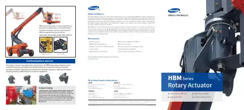
Platform control Arm controlProduct testingTwo dedicated endurance test benches are available in Hengli forvarious life time test requirements from customer side. During Hengliinternal rotary actuator endurance test according to the Henglistandard "Q/HL �������-����", the HBM series rotary actuator fullymeets all the requirements, no obvious failure or wear is found duringappearance inspection and disassembly test after ��,��� times ofdurability test.Customization serviceAccording to customer and application requirements, the HBM series rotary actuators can becustomized with special material and optimized structure to deal with various even harshoperating conditions. Meanwhile according to the installation positions, tripod and horseshoemounting frames in different forms can also be customized.● Low friction coefficient ● High output torque● Long service life ● Customization serviceHENGLI HYDRAULICRotary ActuatorSeriesHENGLI HYDRAULIC© Hengli Hydraulic │ 2020EN │ Print date 11/2020We are looking forward to working with you!As a benchmarking company of Chinese high-end hydraulic transmission industry, Hengli Hydraulic is always devoting to theinnovation and development in the following four areas: production design, manufacturing process, quality improvement andmanagement improvement. We, Hengli Hydraulic, is making effort to realize the intelligent manufacture at the same time thehigh-efficiency and energy saving of the hydraulic components and try to reshape the “Made in China” image throughtechnology innovation. Meanwhile we are committed to creating a new pattern of the world's hydraulics industry andcontribute to global technological innovation.Hengli Hydraulic is dedicated to designing and developing hydraulic transmission products and solutions that meet the realneeds of local customers for the global market based on the diverse market demands, in particular the field of mobilemachinery and tunnel engineering. We, Hengli Hydraulic, take advantage of our years of application experience to provide thecustomer the most optimized solutions, thus establish strong partnerships with our customers and maintain a sustainabledevelopment in a competitive market.• Hydraulic Cylinder• Hydraulic Piston Pump & Motor• Hydraulic Control Valve for Mobile Machinery• Industrial Valve• Hydraulic Pump Unit and SystemFor more detailed information, please visit our website at• High performance Hydraulic Test Bench• High-precision Casting• Pneumatic Components and integrated System• Cold-drawn Seamless Steel Pipe• Surface Coating-Thermal Spray TreatmentWhat we provideCHINANo.99 Longqian Road ,Wujin District,Changzhou 213167TEL: +86 400 101 8889E-mail: *******************JAPAN7F Kyoei Building, 2-1-19 Shibadaimon,Minato-Ku, Tokyo 105-0012, JapanTEL: +81 03 6809 1696E-mail:*******************AMERICA580 Crossroads Parkway, BolingbrookIllinois 60440TEL: +01 630 995 3674E-mail: ***********************GERMANYSperenberger Str. 1312277 BerlinTEL: +49 (30) 72088 – 0E-mail:************************Hengli Hydraulic assumes no responsibility for errors that may exist in brochures, product manuals and other publications. Our products are in continuously development and innovation.Applications information in this brochure is not limited to special condition or applicability in particular industry. Trademarks with Hengli, 恒立, SHLIXIN, LIXIN, 立新and InLine are all ownedby Jiangsu Hengli Hydraulic Co., Ltd. and its subsidiaries and affiliates. Unauthorized use of the above trademarks and the contents of this brochure are prohibited.FeaturesProduct AdvantageLow friction coefficientThe HBM series rotary actuator is independently designed and developed for articulated aerial working platform for arm and platform control. According to customer installation and performance requirement, customized design can be realized accordingly to ensure suitable and flexible operation. Design based on metric unit, unique seal andstructure allows a low friction coefficient and high output torque. In addition, the FEA analysis and endurance test contribute to the product stability and reliability. Compared to similar products on the market, the HBM series rotaryactuator provides a ��% to ��% higher output torque and requires a ��% lower cracking pressure under same product size, allowing a stable operation with higher efficiency and better cracking pressure, which ultimately guarantees a safe, reliable and efficient working of the aerial working platform.Innovative independent designIndependent intellectual property rights obtainedSize and specificationSizeD�(Cover diameter)D�(Barrel diameter)L�(Rotary actuator total length)F�(Output shaft thread)F�(Output shaft thread)F�(Output shaft thread ptch diameter )F�(Output shaft through hole)F�(Output shaft screw hole)F�(Cover side screw size)F�(Cover side screw quantity)F�(Cover side thread pitchdiameter )���������M�� depth �������////���������M�� depth �������////���������M�� depth �������////���������M�� depth ������/M�� depth ��M�� depth ���������������M�� depth �������/M�� depth ��M�� depth ��������������������Size and specificationMaximum output torque (Nm)Maximum moment capacity straddle mounting (Nm)Maximum moment capacity cantilever mounting (Nm)Radial force (kg)Axial force (kg)Rotation (°)Displacement (cc)�����������������������������������������������������������������������������������������������������������������������HBM _ �� / ���Rotation Size Series codeOrdering code���������������������������The key component of the HBM series rotary actuator - the spiral spline for rotation and torque transmission, features in excellent precision, balanced stress distribution and stable transmission. Together with thelow-friction axial bearings and a unique sealing system design, the HBM series rotary actuator has a low friction coefficient during transmission process.High output torqueThrough continuous innovative research and validations, the HBM series rotary actuator is designed in compact structure to make full use of the limit internal space and transmit high output torque via fluidpressure. Compared to similar products on the market, the HBM series rotary actuator provides a ��% to ��% higher output torque under same product size.Long service lifeIn Hengli, comprehensive analysis and calculation on each size of the HBM rotary actuator are implemented in assist of FEA software during design process. Besides, product optimization is continuously carried out to ensure that each size of the product can meet the long service life requirements.Except for normal factory test, two dedicated rotary actuator endurance test benches are available for testsaccording to customer and application requirements, ensuring excellent durability and long service life.HBM Rotary ActuatorSeriesNote:the ordering code above refers only the basic specification and rotary angle. Valve, bushings and other accessories can be customized according to corresponding requirements.。
滑阀电液控制执行机构(BDY9-BⅠ型)使用维护说明书JYF101—OOSS(Ⅰ)编制:校对:审核:审定:九江中船仪表有限责任公司二OO二年十二月一、概述:BDY9-BⅠ型电液控制机构是我厂与中石化北京设计院为炼油厂共同开发研制成的一种新型自动控制装置,专门用于炼油厂催化装置中的滑阀的自动控制。
该执行机构按国家标准GB3836.2-2000《爆炸性气体环境用电气设备第2部分隔爆型“d”》有关规定生产制造成隔爆型装置,防爆标志有dⅡBT4和dⅡCT4两种,dⅡBT4可用于石化企业具有ⅡB级T1-T4组爆炸性气体混合物存在的场所;dⅡCT4可用于石化企业具有ⅡC级T1-T4组爆炸性气体(含氢气)混合物存在的场所。
该执行机构的所有隔爆型装置已经国家指定的检验机关检验合格,并颁发了防爆合格证。
该执行机构接受主控室DC 4~20mA输入信号通过伺服放大器,射流管电液伺服阀,高精度位移传感器组成典型的闭环自动控制系统,使伺服油缸活塞杆按主令信号的变化直线运动,再通过机械联接,使被控制设备的直线位移和输入信号的变化成严格的线性比例关系。
该执行机构具有位置控制精度高,推力大,灵敏度高,响应快,寿命长等特点。
在运行中安全可靠,是炼油厂阀门自动控制更新换代的理想产品,也可应用在化工、冶炼等其他电液自动控制装置中去。
二、产品使用环境1、环境温度:-40℃~55℃2、适用于二类二区ⅡB级、ⅡC级防爆场所,防爆标志dⅡBT4、d ⅡCT4。
三、产品主要技术参数1.动力电源:三相380V 50Hz 功率2.2Kw2.仪表电源:单相220V 50Hz UPS功率0.1 5Kw3.报警触点:自锁、综合报警各一对无源常开触点,触点容量DC24V 1A。
4. 工作状态触点信号1)现场操作指示(有源)2)仪表室操作指示(有源)3) 自保运行指示(有源)5. 伺服油缸工作行程250、400、550、700、850、1000(根据用户要求)6. 系统额定压力9MPa±10%(根据用户要求)7. 最大推力70000N (行程≤550mm)110000N (行程>550mm)8. 自保运行速度≥100mm/s (行程≤550mm)≥60mm/s (行程>550mm)9. 全行程运行速度≥40mm/s (行程≤550mm)≥30mm/s (行程>550mm)10. 位置控制精度:≤1/30011. 分辨率≤1/60012. 仪表室输入信号4~20mA13. 现场调试输入信号0~10V14. 阀位输出信号4~20mA15. 工作液32低凝液压油,热带地区可用N46抗磨液压油。
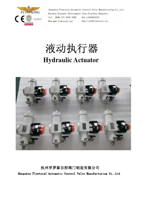
液动执行器Hydraulic Actuator杭州孚罗泰自控阀门制造有限公司Hangzhou Flowtecal Automatic Control Valve Manufacturing Co.,Ltd产品目录 Product catalog一、液动执行器简介及型号说明 Brief introduction & how to selection二、齿轮齿条式液动执行器 Gear rack type hydraulic actuator1.齿轮齿条式液动执行器1-1 F4-P系列齿轮齿条式双作用液动执行器1-2 DHA系列船用液动执行器2-1 F4-P-SR系列单齿条式单作用执行器2-2 F4-P-SRII系列双齿条单作用执行器二、拨叉式液动执行器Scotch yoke hydraulic actuator1. 拔叉式双作用液动执行器2. 拔叉式单作用液动执行器一、液动执行器简介及选型说明:Brief introduction & how to selection1. 液动执行器简介:液动执行器是以液压动力油驱动阀门开闭的阀门执行器。
根据运行方式的不同,可分为角行程液动执行器(主要控制蝶阀,球阀等0-90°旋转开启的阀门),直行程液动执行器(主要控制截止阀,闸阀等直行程开启的阀门)和多回转(Screw Down)液动执行器(需要机械自锁工况要求的阀门)。
液动执行器根据作用方式不同可分为双作用液动执行器和单作用液动执行器。
打开和关闭阀门全部是通过动力油驱动的叫双作用液动执行器;打开或者关闭通过动力油驱动,相反是通过机械复位完成动作的叫单作用液动执行器。
单作用液动执行器可实现三断保护功能(在断电,断控制信号和断动力源的情况下,可以自动关闭或者打开阀门)。
杭州Flowtecal公司研发制造的液动执行器,可以根据工作使用环境的不同,分为浸没型和非浸没型液动执行器。
浸没型液动执行器可浸没在海水下30-60米海水中工作,可长期抗海水腐蚀。
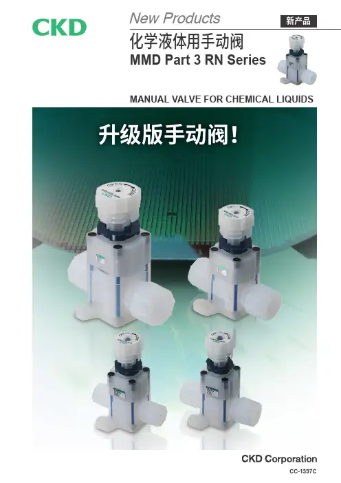
MANUAL VALVE FOR CHEMICAL LIQUIDSMMD Part 3 RN SeriesCC-1397C与以往产品Part 2系列相比,扩大了使用压力范围。
控制压力通用使A 、B 口的使用压力实现通用化。
执行器采用耐化学液体性优异的氟树脂“PVDF ”, 标准型应用非常广泛,酸碱同样适用。
标准规格MMD ※※3RN(Part 3RN )以往产品(Part 2)一般及其它液 体氢氟酸U 规格P 仕様扩大使用压力范围标准型可应对各种液体标准品扩大了流体温度追求易选性和易用性!与以往机种(MMD※※2)相比,标准型扩大了“使用压力范围”、“使用流体”、“流体温度”的覆盖范围。
采用CKD 独创的防锁死结构,增强了安全性!使用压力范围UP!以往产品A 口侧压力[MPa]0.50.40.30.20.100.10.20.30.40.5[MPa]B 口侧压力指示器锁紧环带防锁死机构型手柄120℃80℃MMD ※※3RN(Part 3RN )以往产品(Part 2)带防锁死机构型手柄密封部位在适当锁死的状态下手柄会空转,以防止过度锁死。
开闭盖上罩盖后按入,固定罩盖可上锁或贴上警告标签等。
指示器可确认阀的状态(开或闭)。
锁紧环防止振动等导致手柄意外开闭。
除传统的法兰安装、底面安装外,还增加了4螺孔法兰安装。
法兰安装4螺孔法兰安装底面安装防误操作罩盖盖住控制部位(手柄、锁紧环)防止误操作,避免疏忽大意或沟通不足等人为错误及灾害、事故。
防止密封部位破损目测确认阀的开闭防止误动作3种安装方法防止误操作尺寸种类配管连接3/8̋1/2̋3/4̋1̋10mm12mm25mm记载页码MMD3※3RN MMD4※3RN MMD5※3RN159咔嗒咔嗒新结构1目使用流体流体温度使用压力(A→B )使用压力(B→A )阀座泄漏cm 环境温度安装方式注2:氢氟酸或含氢氟酸的化学液体请在5~80℃的范围内使用。
注3:有关流量特性,请参阅第12页。
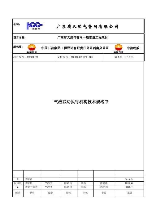
公司:项目名称: 广东省天然气管网一期管道工程项目 承包商: 项目编号:S2009-2D文件编号:GD-CS-GY-SPE-001 第1页 共13页气液联动执行机构技术规格书C 供审查2010.01 报审版 供审批 严静文 陈妍玲 章磊 郭艳林2009.11 A 供业主审查 严静文 陈妍玲 章磊 郭艳林2009.7 版次 说明 编制 校对 审核 审定 日期广东省天然气管网有限公司中国石油集团工程设计有限责任公司西南分公司中油朗威目 录第一部分 基本要求 (3)1 范围 (3)2 名词定义 (3)3项目总体要求 (3)第二部分 通用技术要求 (4)1采用规范、标准及法规 (4)2设计与制造 (4)3检验和测试 (9)4备品、备件及专用工具 (10)5铭牌 (10)6包装和运输 (10)7提交文件 (10)8 技术服务 (11)9 验收 (12)10 售后服务 (12)11 保证和担保 (12)附件:广东省天然气管网项目一期工程气液联动执行机构数据单 (13)注:本文件以初步设计报审版为依据编制。
第一部分 基本要求1 范围本技术规格书包括气液联动执行机构在设计、制造、材料、测试、检验、运输和验收等方面的最低要求。
2 名词定义本技术规格书用到的名称定义如下:业主:广东省天然气管网有限公司。
设计:中国石油集团工程设计有限责任公司西南分公司。
供货商:是指按照本技术规格书的要求为业主设计、制造、提供成套设备的公司或厂家。
分包商:负责设计和制造分包合同所规定设备的公司或厂家。
技术规格书:业主和设计提供的完整的技术规定,包括配套使用的数据单和附图等。
3项目总体要求3.1资格要求供货商应能提供技术先进的成熟产品。
供货商应有近年来在中国国内输气管道上的输气站场或其他相关领域的供货业绩。
供货商需递交气液联动执行机构的实际应用清单,同时用国际单位制标出主要参数。
提供的参数应包括:执行器型号,用户名称和地点,联系电话,供货年份及所配阀门的情况。

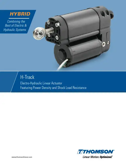
H-Track H-Track – A Compact Hybrid of Superior PerformanceMore Power in Less SpaceH-Track electro-hydraulic actuators feature the smallest mounting envelope in their class with a patented valve and reservoir design that provides significant space savings compared to competitive models. H-Track is a robust linear actuator providing force up to 4800 lbf (21350 N) and travel speeds near 4 in (100 mm) per second. With stroke lengths up to 16 in (406 mm), end switch options and multiple configurations available, the H-Track offers a unique set of options for machine designers.Made for Tough ConditionsH-Track actuators are weatherproof, dust tight, corrosion resistant, and IP67 static (temporary submersion) and IP69K (high-pressure washdown) tested. The H-Track offers an optional operation temperature as low as -40°F (-40°C) to as high as 180°F (82°C), making it an ideal option for use in demanding conditions.H-Track electro-hydraulic actuators provide the high-load performance of hydraulics without the expansive space requirements nor the prohibitive cost of full-sized, fluid-based systems.H-Track Completely Self-ContainedThe motor, pump and valves are contained in one mini power pack mounted directly to the combined cylinder/fluid tank. This means that the inner workings are completely sealed from the outside, allowing this unique arrangement to minimize parts and improve performance. Unlike hydraulic cylinders, there is no need for external hoses, valves, reservoirs or hydraulic connectors that can break or leak. The operation is as simple as with a traditional electric actuator - just turn the supply voltage onto move and change polarity to reverse direction.If necessary, the actuator extension tube can be manually overridden, allowing the tube to float foroperating in emergency situations.3Electro-Hydraulic AdvantagesThe best features from the electric and hydraulic actuator worlds have been chosen to power the H-Track linear actuator, giving it a unique set of capabilities that allow it to be used in applications that otherwise might be too difficult for other solutions to take on.Compact DesignH-Track actuators have a mounting length that is shorter than any other electromechanical actuator on the market. It can fit into applications with a pin-to-pin length as small as 4.8 in (122 mm) plus its stroke, and still provide up to 4800 lbf (21350 N) of force.Superb Load Holding PowerH-Track actuators operate in both tension and compression and will hold a load stationary without power in either direction. Static load holding capability will always exceed the dynamic load moving capability.Vibration and Shock Load ResistantH-Track actuators are immune to vibrational drifting, hydraulically self lock and safely absorb shocks. Energy EfficientElectric control provides clean, smooth linear motion without hydraulic plumbing or other expensive componentry. The H-Track’s power demands are significantly less than those of a full hydraulic system as the actuators require power only when in motion. Solid Extension TubeSince the extension tube is solid, it allows for increased resistance to buckling compared to a hollowextension tube of the same size.5H-Track Hydraulics Isolated from the Atmosphere The fluid reservoir is vented and isolated from the atmosphere with a flexible lid, allowing actuator and pump operation in any orientation without entraining or cavitation.Maintenance-FreeH-Track actuators require no lubrication, hydraulic fluid fillup, or any other type of maintenance or adjustments for their entire lifecycle.Contamination-FreeThe H-Track pump is burnished, cleaned, flushed and vacuum filled with degassed hydraulic fluid. The system is completely sealed with no hoses to leak. This ensures you enjoy contaminant-free performance for the life of the actuator.Thoroughly TestedThroughout their entire development process, H-Track actuators are rigorously tested to ensure they meet all relevant standards and performance specifications prior to leaving the factory. Please contact Thomson customer support to learn more about which standards H-Track meets and how our testing is carried out.CustomizationAs with most Thomson products, H-Track actuators can be customized. Our engineers will work with you to determine the modifications needed – from a simple color change to a complete overhaul of the design. Thomson is a global leader in custom actuator production and takes pride in supplying the optimal solution to each customer.6Built to PerformH-Track is one of the strongest actuators for its size without compromising life expectancy or the ability to withstand the elements.1Compact and strong power pack unit, containing pump, valve and motor 2Fluid tank integrated into the cover tube3Solid small-diameter, buckling-resistant extension tube312Get the best from the electric and hydraulic worlds in one package. H-Track is powerful, tough, and vibration and shock load resistant.Yet it only needs a battery and a switch to run, requires no maintenance, and minimizes the risks and hazards associated with hydraulic fluid leaks.4Power pack unit completely sealed from the outside 5Two-wire operationLarge number of power pack and cylinder configurations allow for great design flexibility4 685H-Track is built from the outside in to excel in situations where many otheractuators are forced to bow out. The unique electro-hydraulic design combines the best features from two distinct systems and opens up new application possibilities for linear actuators.7H-Track 410H-Track is designed and tested to operate under the harshest conditions without failure or the need for maintenance.10IP69K/IP67 protection class 13Large operating temperature range 11Chrome finished steel extension tube 14High shock load and vibration resistance 12Salt spray tested for 200 hoursAnodized aluminum alloy housing1912101178211976Built for the Toughest ApplicationsWith a self-contained electro-hydraulic system, H-Track actuators meet the growing demand for power-dense performance used in a variety of industrial applications, including agricultural sprayer booms, snow plow blades and mower deck lifts.Designed to Withstand Life on the FieldsWith agricultural sprayers becoming larger and boom lengths reaching up to 177 ft (54 m), strain on the actuators has increased exponentially. Actuators are used to fold the long sprayer booms from an extended position to a stowed position for transport. The folding and unfolding of these booms apply very high loads on the actuators. The strain on the units is dramatically increased when the sprayeris in motion and the bouncing of the booms causes even more extreme loads. These combined loads create tremendous impact force that can easily destroy most other electric actuators. The H-Track is designed to handle this type of loading with ease.8H-Track Ideal for Demanding Outdoor ApplicationsWhere the often harsh outdoor environmentcreates conditions that can be fatal for mostactuators, the H-Track thrives. A snow plowbattling icy roads and striking a stationary, concreteobject is an example that would quickly destroymost linear actuators. The H- T rack’s unique valveand reservoir design gives it the ability to cushionthese blows and continue operating without issue.The optional ability to operate in temperatures aslow as -40°F (-40°C) makes it a perfect fit for eventhe coldest climates. Mower deck lifts are typicallywhere electric actuators shine, but with increasingdeck sizes and ground speeds, the limits of thesetraditional actuators are being exceeded. Withits reliable, load-holding capabilities, enhanceddurability for higher transport speeds, and ability towithstand high-pressure washdowns, the H-Trackis a perfect choice for the next generation of larger,faster mowers.9Technical FeaturesH-Track Electro-Hydraulic Linear Actuator • Combines the best from the hydraulic and electric worlds.• High power density.• Very compact and short pin-to-pin versus stroke length relationship.• Solid extension tube allows for increased resistance to buckling.• Immune to vibrational drifting and hydraulically self locks.• High shock load and vibration resistance.• Fluid reservoir is vented and isolated from the atmosphere with a flexible lid, allowing actuator and pump operation in any orientation withoutentraining or cavitation.• Standard strokes up to 16 in (406 mm).• Designed for harsh outdoor conditions.•Reliable and maintenance free.H-TrackTechnical SpecificationsElectrical ConnectionsF FuseS1 Double pole double throw switchTo extend the actuator, apply +Vdc to black (white) and -Vdc to grey (green/white). To retract, apply-Vdc to black (white) and +Vdc to grey (green/white). Colors in between brackets are valid for the 560 W motor. Avoid running the actuator in to the ends.DimensionsH-Track DimensionsWeightbut at temperatures below 40°F (4°C), force and current begin to increase, while speed decreases. At temperatures above 120°F (50°C), speed will decrease slightly. The exact amount of performance change is difficult to calculate. Also, when it comes to the lower temperature span, the performance will move towards what is stated above as the temperature rises in the actuator due to the heat generated by its work. Please consult Thomson customer service for more information.Performance MatrixH-Track Ordering KeySizing and SelectionIn order to choose the optimal H-Track actuator for your application, please follow the sizing and selection process as described below. Do not hesitate to contact Thomson customer support if you need assistance.Step 1. Determining Load ConfigurationDetermine which load configuration (C, H, N or B) is valid for your application. Also see page 18.Example: Assuming that the load needs to be pushed horizontally, and the extenson tube will not be affected by gravity when pushing or pulling, then the application corresponds to load configuration N.Step 2. Bore and Extension Tube SizingDetermine which bore size is needed for your load and stroke. Also see page 19.Example: Assuming the application requires 16-in stroke, and that load is 2500 lbf at extension (red dot) and 500 lbf at retraction (yellow dot), then the Stroke vs. Load and Bore Size diagram below shows, that only the blue curve is above both points. Therefore, bore size H3 is the only possible choice in this case.Stroke vs. Load and Bore SizeStroke [in]Bore SizeH1H2H3L o a d [l b f (N )]0 2 4 6 8 10 12 14 16 18 20 22 245500 (24464)5000 (22240)4500 (20016)4000 (17792)3500 (13344)3000 (13344)2000 (8896)1500 (6672)1000 (4448)500 (2224)H-TrackStep 3. Sizing of Motor, Pump and Power Supply Determine the size of the actuator motorand pump for your application, as wellas the current draw by referring to the diagrams on pages 20 - 22.Example: Since the load configuration in step 1 was determined to be of type N, refer to the diagrams on page 22.In the Load vs. Speed diagrams for load configuration N, the maximum extension and retraction loads that were assumed in step 2 are shown by the vertical lines. In this example, we also assume that a travel speed of 0.25 in/s is required when extending and 1 in/s when retracting. The only H3 bore size of the four that can deliver that speed when extending at 2500 lbf and retracting at 500 lbf is model H3N-xx-2B23.In order to size the power supply, you must decide which voltage to use and themaximum load currect draw at extensionand retraction. To do that, first determine the percentage of the maximum permissible load that is used in each direction.According to the Load vs. Speed diagram, H3N-xx-2B23 has a maximum load of about 2700 lbf at extension and 2000 lbf at retraction (the exact max. load values can be found in the Performance Matrix on page 14). The assumed maximum loads needed in the application, which requires 2500 lbf at extension and 500 lbf at retraction, are about 92% (red line) and 25% (yellow line) of the maximum permissible loads. The current forH3N-xx-2B23 equipped with a 24 Vdc motor (model H3N-24-2B2) would, in this case, follow the dotted red line and be about 20 A at extension and 40 A at retraction. Be sure to size your power supply with some margin.Step 4. Finishing the Ordering CodeAt this point, the ordering code is H3N-24-2B23-xxxx. In order to complete it, the type of extension tube front adapter, the stroke length and the rear adapter orientation need to be determined. Also see page 15.Example: In step 2, it was assumed the application required a 16-in stroke, which means the code becomes H3N-24-2B23-x16x. If we assume a standard front adapter and a 90° rear adapter orientation are required, the complete ordering code would be H3N-24-2B23-A16R.Load vs. Speed @ Extension Load vs. Speed @ RetractionC u r r e n t [A ]S p e e d [i n /s (m m /s )]Load [lbf (N)]12 Vdc Actuators Bore Size H124 Vdc Actuators Bore Size H248 Vdc ActuatorsBore Size H3Percent of Maximum Permissible Load [%]H1N-xx-1B11 H1N-xx-1B41H1N-xx-2B11H1N-xx-2B41HxN-12-1xxx HxN-12-2xxx HxN-24-1xxx HxN-24-2xxx HxN-48-1xxxHxN-48-2xxx H2N-xx-1A12 H2N-xx-1B42H2N-xx-2A22H2N-xx-2B32H3N-xx-1A13 H3N-xx-1B23H3N-xx-2A13H3N-xx-2B23Load vs. CurrentDetermining Load ConfigurationThere are four main types of load and gravity configurations, which will determine the performance of the actuator. Please refer to the configurations below and choose the one that best corresponds to your application. Contact Thomson customer support if you are unable to determine a valid configuration for your application.Configuration CThe gravity resists the load being moved when the actuator extends and helps it when retracting. Configuration NThe gravity does not affect the load in any direction.Configuration HThe gravity helps the load being moved when the actuator extends and resists it when retracting.Configuration BThe gravity both helps and resists the load being moved in both directions except at one point where the load is not affected by the gravity at all. If this is your configuration, try to re-design the mechanical linkage so that the result is a C, H or N configuration. Please contact Thomson customer support if that is not possible.H-TrackSizing of Bore and Extension TubeStroke vs. Load and Bore SizeStroke [in]Bore SizeH1H2H3L o a d [l b f (N )]0 2 4 6 8 10 12 14 16 18 20 22 245500 (24464)5000 (22240)4500 (20016)4000 (17792)3500 (13344)3000 (13344)2500 (11120) 2000 (8896)1500 (6672)1000 (4448)500 (2224)The maximum load in each direction and the required stroke length determine the minimum bore and extension tube size needed for the actuator. Refer to the diagram below todetermine which bore size your application requires. If no solution exists, the stroke and/or load must be reduced. Contact Thomson customer support if you are unable to determine a valid combination for your application.Sizing of Motor, Pump and Power SupplyLoad vs. Speed @ ExtensionLoad vs. Speed @ RetractionC u r r e n t [A ]S p e e d [i n /s (m m /s )]Load [lbf (N)]12 Vdc ActuatorsBore Size H124 Vdc ActuatorsBore Size H248 Vdc ActuatorsBore Size H3Percent of Maximum Permissible Load [%]H1C-xx-1B11 H1C-xx-1B41H1C-xx-2B11H1C-xx-2B41HxC-12-1xxx HxC-12-2xxxHxC-24-1xxx HxC-24-2xxxHxC-48-1xxx HxC-48-2xxxH2C-xx-1A12 H2C-xx-1B32H2C-xx-2A22H2C-xx-2B32H3C-xx-1A13 H3C-xx-1B23H3C-xx-2A13H3C-xx-2B23Load vs. Current21H-TrackSizing of Motor, Pump and Power SupplyLoad vs. Speed @ ExtensionLoad vs. Speed @ RetractionC u r r e n t [A ]S p e e d [i n /s (m m /s )]Load [lbf (N)]12 Vdc ActuatorsBore Size H124 Vdc ActuatorsBore Size H248 Vdc ActuatorsBore Size H3Percent of Maximum Permissible Load [%]H1H-xx-1B11 H1H-xx-1B41H1H-xx-2B11H1H-xx-2B41HxH-12-1xxx HxH-12-2xxxHxH-24-1xxx HxH-24-2xxxHxH-48-1xxx HxH-48-2xxxH2H-xx-1A12 H2H-xx-1B32H2H-xx-2A22H2H-xx-2B32H3H-xx-1A13 H3H-xx-1B23H3H-xx-2A13H3H-xx-2B23Load vs. Current22Sizing of Motor, Pump and Power SupplyLoad vs. Speed @ ExtensionLoad vs. Speed @ RetractionC u r r e n t [A ]S p e e d [i n /s (m m /s )]Load [lbf (N)]12 Vdc ActuatorsBore Size H124 Vdc ActuatorsBore Size H248 Vdc ActuatorsBore Size H3Percent of Maximum Permissible Load [%]H1N-xx-1B11 H1N-xx-1B41H1N-xx-2B11H1N-xx-2B41HxN-12-1xxx HxN-12-2xxxHxN-24-1xxx HxN-24-2xxxHxN-48-1xxx HxN-48-2xxxH2N-xx-1A12 H2N-xx-1B32H2N-xx-2A22H2N-xx-2B32H3N-xx-1A13 H3N-xx-1B23H3N-xx-2A13H3N-xx-2B23Load vs. Current23H-Track Thomson offers a wide variety of online tools to help you in the sizing and selection process. An experienced team of engineers is also available to help size and select an H-Track model to best fit your application needs. To explore additional technical resources and options, contact customer support at /cs.Online ResourcesInteractive 3D CAD ModelsDownload free interactive 3D CAD models in the most common CAD formats./H-Track-cadH-Track on the WebGet additional information and learn more about H-Track on this content-rich web page. /h-trackH-Track Overview VideoLearn about this electro-hydraulic actuator with this brief, informative video./H-Track-video24Is H-Track suitable for tough environments such as washdown or extreme temperatures? Yes. H-Track actuators are designed for washdown and have passed 200 hours of salt spray tests. They can operate in temperatures ranging from -20 to +65°C (-20 to +150°F).How is the duty cycle determined?The duty cycle = on time / on time + off time. For example, if H-Track is powered for 15 seconds and then off for 45 seconds, the duty cycle for that minute would be 25%. All models are rated to 25% at full load, and an ambient temperature of 25°C (77°F). If load and/or ambient temperature are lower, then the duty cycle can exceed 25%. At higher temperatures, the duty cycle will be lower. Can H-Track be side loaded?No. A proper design of the application should eliminate any side loads.Frequently Asked QuestionsWhat is the typical life of an actuator?Life is a function of load and stroke length. Please contact customer support for more information.What are the most common reasons for premature actuator failure?Side load due to incorrect mounting, shock loading, exceeding the duty cycle and incorrect wiring are the most prominent causes of premature failure.Is H-Track maintenance free?Yes, it never requires lubrication, maintenance or adjustment for wear.What are IP ratings?Ingress Protection (IP) ratings are commonly referenced standards that classify electrical equipment using standard tests to determineresistance to ingress of solid objects (first digit) and liquids (second digit). See the IP Ratings table below.25H-Track Is it possible for a load to back-drive the extension tube?H-Track is self locking up to at least the maximum static load. Higher static load may result in damage and back driving.What is the difference between a tension and a compression load?A tension load tries to stretch the actuator, while a compression load tries to compress it. With bi-directional loads, the end play of the actuator extension tube may need to be taken into consideration when using the actuator for positioning tasks.What is the range of input voltage an H-Track can operate with?A 12 Vdc version will accept 9 – 16 Vdc, a 24 Vdc 18 – 32 Vdc and a 48 Vdc 36 – 64 Vdc. Outside of these limits, operation may be erratic and the actuator permanently damaged.Is H-Track protected against overheating? Yes, the motor incorporates a thermal switch in the windings to shut off the actuator motor in case of overheating or high overcurrent.Can the speed of an H-Track be adjusted by changing the input voltage?Yes, as long as the voltage is within the acceptable input voltage limits.What is the inrush current?The inrush current is a short current peak that appears at the start of an actuator as the motor tries to get the load moving. Typically, the inrush current will last between 75 – 150 milliseconds and can be up to three times higher than the current for the actuator and load. Batteries have no problem delivering the inrush current, but if using an AC power supply, it is important to size it to handle the inrush current.What special mounting considerations does the H-Track require?There is no restraining torque that needs to be considered as H-Track is internally restrained. However, the actuator must be mounted so that there are no side loads acting on the extension tube. What is the maximum travel speed?The travel speed of an H-Track actuator is a linear function of the load. To determine the speed at a certain load and direction, consult the load vs. speed diagrams on pages 18 - 20. If a higher linear travel speed is required, a simple mechanical linkage canbe employed.Tension CompressionH-Track27H-Track_BREN-0035-03 | 20230125TJSpecifications are subject to change without notice. It is the responsibility of the product user to determine the suitability of this product for a specific application. All trademarks property of their respective owners. © 2023 Thomson Industries, Inc.USA, CANADA and MEXICO Thomson203A West Rock Road Radford, VA 24141, USA Phone: 1-540-633-3549Fax: 1-540-633-0294E-mail:*************************Literature: EUROPEUnited Kingdom ThomsonOffice 9, The BarnsCaddsdown Business Park Bideford, Devon, EX39 3BT Phone: +44 1271 334 500E-mail:******************************Germany ThomsonNürtinger Straße 7072649 Wolfschlugen Phone: +49 7022 504 403Fax: +49 7022 504 405E-mail:******************************France ThomsonPhone: +33 243 50 03 30E-mail:******************************Italy ThomsonVia per Cinisello 95/9720834 Nova Milanese (MB)Phone: +39 0362 366406Fax: +39 0362 276790E-mail:*****************************Sweden Thomson Estridsväg 1029109 Kristianstad Phone: +46 44 590 2400Fax: +46 44 590 2585E-mail:******************************ASIAAsia Pacific ThomsonE-mail:****************************China ThomsonRm 805, Scitech Tower 22 Jianguomen Wai Street Beijing 100004Phone: +86 400 606 1805Fax: +86 10 6515 0263E-mail:*****************************IndiaKollmorgen – Div. of Altra Industrial Motion India Private LimitedUnit no. 304, Pride Gateway,Opp. D-Mart,Baner Road, Pune, 411045MaharashtraPhone: +91 20 67349500E-mail:**************************South Korea Thomson3033 ASEM Tower (Samsung-dong) 517 Yeongdong-daeroGangnam-gu, Seoul, South Korea (06164)Phone: + 82 2 6001 3223 & 3244E-mail:*****************************SOUTH AMERICA Brazil ThomsonAv. João Paulo Ablas, 2970Jardim da Glória - Cotia SP - CEP: 06711-250 Phone: +55 11 4615 6300E-mail:******************************。
液动执行器规格书一.设备用途及基本要求液动执行器结构简单、紧凑、体积小。
传动平稳可靠,有缓冲无撞击现象。
可根据需要采用不同的液压油,可在-45℃~+120℃温度范围内工作,能防爆。
可以获得很大的输出力矩,适合任何规格。
输出力矩可以通过液压泵提供的压力精确的调整,泵站提供压力可以通过压力表直接反映出来。
在突然发生事故动力终断时,仍可利用泵站上的蓄能器进行一次或数次动力操作。
产品概述:1、结构简单、紧凑、体积小。
2、齿条齿轴传动平稳可靠,有缓冲无撞击现象。
3、可根据需要采用不同的液压油,可在-45℃~120℃温度范围内工作。
能防爆。
主要特点:1 液源压力: 6.3~10MPa2 回转角度:90±5°3 液源接口:M16×1.56 工作环境温度:-20℃~±90℃,特殊-45℃~120℃7.液动执行器型号:Y-OIS、Y-01D双作用液动执行器(干式不带限位开关)DN H H1 H2 H3 L L1 50 275 190 105 140 190 160 60 290 205 106 141 206 181 70 380 266 134 170 250 217DN H H1 H2 H3 L L1 80 470 340 150 190 280 250 100 580 460 190 240 325 295DN H H1 H2 H3 L L1 双缸80 730 580 170 215 360 330 双缸100 810 641 210 260 440 410双作用液动执行器(干式带限位开关带支架)DN H H1 H2 H3 L L150 275 190 105 211 190 160 60 290 205 106 212 206 181 70 380 266 134 240 250 217DN H H1 H2 H3 L L1 80 470 340 150 256 280 250 100 580 460 190 296 325 295DN H H1 H2 H3 L L1 双缸80 730 580 170 276 360 330 双缸100 810 641 210 316 440 410双作用液动执行器(干式带限位开关不带支架)DN H H1 H2 H3 L L150 275 190 105 185 190 160 60 290 205 106 212 214 181 70 380 266 134 240 231 217双作用液动执行器(浸没式)DN H H1 H2 L L150 275 190 120 190 160 60 290 205 121 206 181 70 380 266 149 250 217(可根据厂家需求制作大通径浸没式液动执行器)单作用液动执行器DN H H1 H2 L L1 5060 205 121 206 181 70DN H H1 H2 H3 L L1 80 470 340 150 256 280 250 100(可根据用户需求需求制作大通径单作用执行器)安装使用及维修注意事项1. 双作用液动执行器结构组成液动执行器主要由缸体①、齿条②、齿轴③、法兰④、导成套⑤、行程螺杆⑥、⑦、应急阀块⑧、限位开关盒体⑨、盖头⑩等组成。
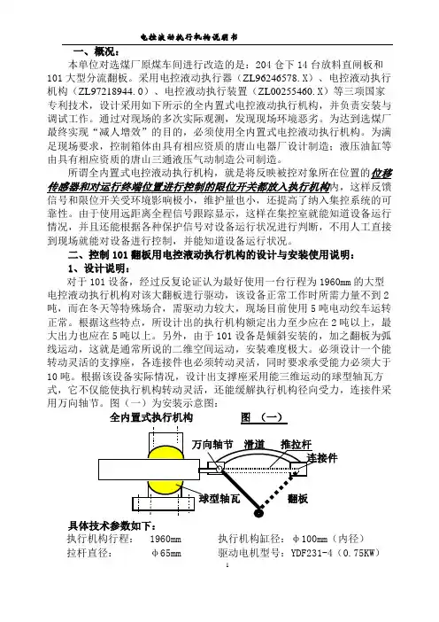
一、概况:本单位对选煤厂原煤车间进行改造的是:204仓下14台放料直闸板和101大型分流翻板。
采用电控液动执行器(ZL96246578.X)、电控液动执行机构(ZL97218944.0)、电控液动执行装置(ZL00255460.X)等三项国家专利技术,设计采用如下所示的全内置式电控液动执行机构,并负责安装与调试工作。
通过对现场的多次实际观测,发现现场环境恶劣。
为达到选煤厂最终实现“减人增效”的目的,必须使用全内置式电控液动执行机构。
为满足现场要求,控制箱体由具有相应资质的唐山电器厂设计制造;液压油缸等由具有相应资质的唐山三通液压气动制造公司制造。
所谓全内置式电控液动执行机构,就是将反映被控对象所在位置的位移传感器和对运行终端位置进行控制的限位开关都放入执行机构内,这样反馈信号和限位开关受环境影响极小,维护量也小,还提高了纳入集控系统的可靠性。
由于使用远距离全程信号跟踪显示,这样在集控室就能知道设备运行情况,并且还能根据各种保护信号对设备运行状况进行判断,不用人工直接到现场就能对设备进行控制,并能知道设备运行状况。
二、控制101翻板用电控液动执行机构的设计与安装使用说明:1、设计说明:对于101设备,经过反复论证认为最好使用一台行程为1960mm的大型电控液动执行机构对该大翻板进行驱动,该设备正常工作时所需力量不到2吨,而在冬天等特殊场合,需驱动力较大,现场目前使用5吨电动绞车运转正常。
根据这些特点,所设计出的执行机构额定出力至少应在2吨以上,最大出力也应在5吨以上。
另外,由于101设备是倾斜安装的,加之翻板为弧线运动,这就是通常所说的二维空间运动,安装难度极大。
必须设计一个能转动灵活的支撑座,各连接件也必须转动灵活,同时要求承受能力必须大于10吨。
根据该设备实际情况,设计出支撑座采用能三维运动的球型轴瓦方式,它不仅能使执行机构转动灵活,还能缓解执行机构径向受力,连接件采用万向轴节。
图(一)为安装示意图:具体技术参数如下:执行机构行程: 1960mm 执行机构缸径:φ100mm(内径)拉杆直径:φ65mm 驱动电机型号:YDF231-4(0.75KW)电机额定电流: 2.6A 电机额定电压:~380V电机防护等级: IP44 齿轮泵型号:CBWS-E310齿轮泵额定压力:16MP 执行机构额定工作压力:约5MP执行器额定出力:23KN~40KN 执行器最大出力: 80KN左右执行器运行时间:40秒~76秒执行器工作介质:46号耐磨液压油2、使用说明:执行机构简易原理图和主要功能如下:1执行机构2齿轮泵3阀门电机4油箱5换向阀6信号板7出线嘴8油管9连接件10支架11传感器和行程开关其工作原理是:油泵将油箱中的油抽出加压后给换向阀,通过它控制执行机构拉杆的移动方向。
Xpac 系列REXA Xpac 是一款性能卓越的定位装置,特别适合于需要精密控制和高可靠性的应用。
该产品在设计时即着眼于应对最恶劣的运行环境,并能够掌控最苛刻的工艺条件。
借助我们生产的执行器和驱动装置,最终控制元件将能够与最为精密的仪器仪表和分布式控制系统实现完美衔接。
基本组件Xpac 由两个主要组件构成:执行器和控制箱。
执行器装在被驱动装置上,由液压缸、反馈装置和 Electraulic™(电液执行器)动力组件所组成;控制箱则单独安装,由电子元件和电源组成。
Electraulic Actuation动力模块采用 REXA 公司独有的自备式液压泵系统,可控制双作用液压缸的油压和进出流速。
Xpac由控制箱中的专用微处理器 (CPU) 操控。
这款执行器的设计堪称机械、液压和电子技术的完美融合。
标准配置REXA 提供以下标准配置:直线型执行器(L 系列),其推力为2000-120000磅(9kN –534kN),行程可达 6 英寸(152mm);旋转型(R系列),其转角可达 90 度,力矩范围2500 – 400000磅・英寸寸(282Nm – 45194Nm);以及驱动型(D 系列),力矩可达 200000磅・英寸寸(22597Nm),转角可达 120 度。
定制机组可提供更大推力或力矩以及更大行程或转角。
我们可提供力矩高达数百万磅・英寸的驱动装置。
Electraulic Actuation 动力组件包括B、C、 ½D、D等多种型号。
不同的动力组件可针对特定缸体尺寸提供多种运行速度及更好的频率响应。
这种产品配置方式可实现极高的通用性,从而降低了备件库存。
应用任何涉及到工艺控制的行业均可利用 Electraulic Actuation ™技术提高其收益。
电力、石油天然气管道、市政供水和废水处理等行业将受益匪浅,而其他很多行业,例如造纸、采矿、石油化工等行业也会从中受益。
不同的应用将会给阀门和风门挡板带来诸多挑战。
胜利油田胜利勘察设计技术规格书项目号:BZGDQG01研究院有限公司文件号:SPE-0400IN01-16工程设计证书:A137004927天然气长输管道标准化设计采购文件模板气液联动执行机构CADD号:SPE-0400IN01-16-B.DOCA237004924 设计阶段:工程勘察证书:150004-kj 日期:2013,05,15 专业控第 1 页共13页B版目录1 适用范围 (3)2 相关文件 (3)2.1标准及规范 (3)2.2技术文件 (4)2.3 优先顺序 (4)3 供货商要求 (4)3.1 供货商资质要求 (5)3.2 供货商应提供的背景资料 (5)4 供货范围及工作范围 (5)4.1 概述 (5)4.2 供货范围 (5)5 基础条件 (6)6 技术要求 (6)6.1 总则 (6)6.2 执行机构 (7)6.3 电子控制单元 (8)6.4 材料 (9)7 验收试验 (10)7.1 总则 (10)7.2 执行机构的测试 (10)7.3 执行机构与阀门组装后的整体测试 (10)7.4 现场测试 (10)8 铭牌 (11)9 包装与运输 (11)10 备件及专用工具 (11)11 文件要求 (11)11.1 文件基本要求 (11)11.2 文件清单 (11)12 服务与保证 (13)1 适用范围本技术规格书为气液联动执行机构专用技术规格书,是对气液联动执行机构及其相关附件提出的最低技术要求。
工程名称和基础条件及对铭牌、包装与运输、备件及专用工具、服务与保证等的基本要求请见《仪表通用技术规格书》。
2 相关文件2.1标准及规范下列文件中的条款通过本技术规格书的引用而成为本技术规格书的条款。
凡是注明日期的引用文件,其随后所有的修改单或修订版均不适用于本技术规格书;凡是不注明日期的引用文件,其最新版本适用于本技术规格书。
当国内外标准、规范发生冲突时,以执行严格的标准为原则。
表2.1-1 标准及规范清单编号名称GB 150 压力容器GB 3836.1 爆炸性环境第1部分:设备通用要求GB 3836.2 爆炸性环境第2部分:由隔爆外壳“d”保护的设备GB 50058 爆炸和火灾危险环境电力装置设计规范GB/T 11021 电气绝缘耐热性分级JB/T 7352 工业过程控制系统用电磁阀ANSI B 1.20.1 Tube Screw ThreadASME Boiler and Pressure V essel CodesASME B16.5 Pipe Flanges and Flanged FittingsASME B31.3 Process PipingASME B31.8 Gas Transmission and Distribution Pipeline SystemsASTM F1030 Standard Practice for Selection of V alve OperatorsIEC 60079 Electrical apparatus for explosive gas atmospheresIEC 60085 Electrical insulation – Thermal evaluation and designation编号名称IEC 60529 Degrees of protection provided by enclosures (IP Code)ISA 75.01 - ISA75.22 ISA control valve Standards2.2技术文件主要参照的技术文件包括:表2.2-1 技术文件清单序号文件号名称版次1 SPE-0400IN01-XX仪表通用技术规格书2 DDS-0400IN01-XX 气液联动执行机构数据表2.3 优先顺序若本规格书与有关的其它规格书、数据表、图纸以及上述规范和标准出现相互矛盾时,应遵照下列优先次序执行。
华能岳阳电厂EKS 液动执行机构一、概述EKS 执行器由英国ELERM 公司生产,全部用在锅炉的风.烟系统的调节部分.每台机组有24台EKS 执行器,全厂共2Χ24台,具体配置如下;磨组二次风挡扳;2Χ8台 (A .,左右侧布置.)磨组一次风挡扳; 2Χ4台磨组一次热风挡扳; 2Χ4台磨组一次冷风挡扳: 2Χ4台引风机出口导叶: 2Χ2台 A/B 侧布置一次风机出口导叶: 2Χ2台由于执行器所承担的任务不同,各执行器的性能参数也不尽相同,如下表.伸缩力Kg 动作速度mm/s 行程mm 工作压力Bar 马达电源引风机导叶 1240 31 300 90 380VA.C二次风挡扳 890 42.4 424 65 380VA.C一次风机导叶 755 31 300 65 380VA.C一次风挡扳 345 31 297 25 380VA.C热风挡扳 345 31 297 25 380VA.C冷风挡扳 140 31 297 10 380VA.C从上知,执行器全开或全关动作时间约10秒钟,如果动作达不到该要求,则要通过调节AP500内灵敏度(死区)来达到目的.总之,EKS 执行器最大优点是调节性能好,准确度高,不足之处在于工作环境恶劣,漏油,渗油现象较为普遍,机械卡涩也有发生,在开.停机时由于热胀冷缩表现得尤为明显.二、结构.主要拐臂,支承架,活塞保护套,活塞杆,LVDT 反馈杆,控制盘(内含限位开关LS1-LS6.全开2个,全关2个,中间2个).AP500控制器盒,端子盒,油泵,马达,380VA.C 接线盒,油箱(上面有油位计.泄油孔.注油孔),过滤器,电磁阀2个,减压阀3个,手动切换装置,手动操作手柄,手动油泵,压力开关等组成.如图1和图2RV1 RV2图1 液动执行器正面图切换手柄 手动油泵图2 液动执行器侧面图三、工作原理.1、液压油路工作原理:两种工作方式;就地手动操作和AP500控制.A、AP500控制器控制时:EXT/RET 打在收缩方向(RET)则电磁阀A 带电,油从③回路进④ 回路出,EKS 执行器收缩,EXT/ERT 开关打在EXT 方向,则电磁阀B 带电油从④回路进③回路出,EKS 伸长.B 、就地手操:切换手柄放在手动控制伐的RETRACT 侧,油从①回路进②回路出,EKS 收缩,若切换手柄放在EXTREND 侧,则由油从②回路进①回路出,EKS 伸长.2、执行器电路工作原理:A 、合上380V A.C 开关柜上隔离开关在N-90系统发出 START PUMP ”信号(MCS:F8-F11的07→P →,油泵接触器线川PC 带电,其接点PC1和PC2均闭合,油泵马达运行,其中PC2起保持作用,使油泵接触川不掉电.图3B 、在CCR 上增加挡扳指令信号或在控制器内把EXT/RET 开关切至EXT 方向,则AP500内固态继电器SSR1导通,EXT 电磁阀SOL1带电,EKS 执行器伸长.在CCR 上减少挡扳指令或在AP500内把EXT/RET 开关切向RET 方向,则AP500内固态继电器SSR2导通,RET电磁伐带电EKS执行器收缩.C、收缩限位开关LS1和伸长限位开关LS2以及PS2压力开关的作用:执行器全开时,LS2才断开,此时断开相应的执行器伸长电路,使电磁阀SOL1不带电,避免电磁伐长期带电烧坏,并保证执行器不因过力矩而损坏,同理,执行器全关时,LS1才断开,断开相应的执行器收缩电路,使电磁阀SOL2不带电,防止电磁伐长期带电损坏和保证执行器不因过力矩而损坏. PS2设在伸长电路中,主要是油压来达到预设压力下断开电路,防止电磁伐带电而伐门(挡扳)却操不动。
液动执行器规格书
一.设备用途及基本要求
液动执行器结构简单、紧凑、体积小。
传动平稳可靠,有缓冲无撞击现象。
可根据需要采用不同的液压油,可在-45℃~+120℃温度范围内工作,能防爆。
可以获得很大的输出力矩,适合任何规格。
输出力矩可以通过液压泵提供的压力精确的调整,泵站提供压力可以通过压力表直接反映出来。
在突然发生事故动力终断时,仍可利用泵站上的蓄能器进行一次或数次动力操作。
产品概述:
1、结构简单、紧凑、体积小。
2、齿条齿轴传动平稳可靠,有缓冲无撞击现象。
3、可根据需要采用不同的液压油,可在-45℃~ 120℃温度范围内工作。
能防爆。
主要特点:
1 液源压力: 6.3~10MPa
2 回转角度:90±5°
3 液源接口:M16×1.5
6 工作环境温度:-20℃~±90℃,特殊-45℃~120℃
7.液动执行器型号:Y-OIS、Y-01D
双作用液动执行器(干式不带限位开关)
双作用液动执行器(干式带限位开关带支架)
双作用液动执行器(干式带限位开关不带支架)
双作用液动执行器(浸没式)
(可根据厂家需求制作大通径浸没式液动执行器)
单作用液动执行器
(可根据用户需求需求制作大通径单作用执行器)
安装使用及维修注意事项
1. 双作用液动执行器结构组成
液动执行器主要由缸体①、齿条②、齿轴③、法兰④、导成套⑤、行程螺杆⑥、⑦、应急阀块⑧、限位开关盒体⑨、盖头⑩等组成。
装配分为3大块:应急阀块、法兰装配、缸体装配
1、在安装前应仔细核对型号是否与使用要求符合。
2、本执行器可安装任何工作位置,但应考虑检修和操作的方便。
3、在安前应对执行器进行密封性能试验;在安装前还应进行三次以上的空载开关试验,主轴转动应灵活,各种轴件不应有卡阻现象。
4、安装过程中应清除孔内、密封圈及接合面的污垢的杂物,检查连接螺栓是否均匀拧紧。
5、安装完毕要进行密封试验及液动操作试验。
6、在使用期间,应视其动频繁程度进行定期检查和维护。
故障及现象的分析。