
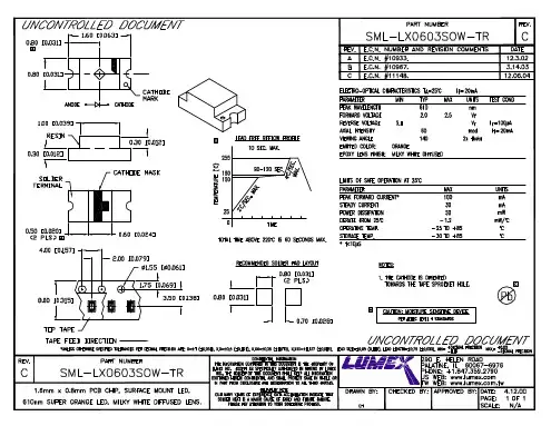
SML-LX0603SOW-TR中文资料
- 格式:pdf
- 大小:61.55 KB
- 文档页数:1

Artikelnummer / part number :823 56 120 100Datum / Date :2006-10-15Bezeichnung :description :0603 ESD SuppressorSMD size:0603A Mechanische Abmessungen / dimensions :SIZE(Unit : mm)B Elektrische Eigenschaften / electrical properties :TECHNICAL DATAWorking Max. ClampingTyp.Leakage ESD Pulse ESD Voltage Voltage Voltage Clamp. V Current Withstandair dischargeDC V(*1)V (*2)µA (*3)kV (*4)pF Spezifikation für Freigabe / specification for releasePart NumberKunde / customer :CapacitanceROHS Compliant823 56 120 1001260-1-+/-1510* 1 Max. Clamping Voltage at 8/20 waveformand 1 A pulse current Capacitance tolerance:+/-30%* 2 Typ. Clamping Voltage per 8 kV ESD contact discharge methodCapacitance measured at:1MHz* 3 Leakage Current at max operating voltage, the max leakage current was measured at reliability test * 4. ESD Typ. Withstands Voltage design and method guarantee this propertyWAVE FORMESD LEVEL IEC61000-4-2Severity Level Air DischargeDirect Discharge1 2 kV 2 kV 2 4 kV4 kV 38 kV 6 kV 415 kV 8 kV 5Special SpecialREFERENCE DATA Response timeT rise <1ns Operating ambientg temperature -40~+85℃Storage temperature -50~+125℃Max. temperature solder 260/10s℃OTHER DATA BodyZnO End termination Ag/Ni/Sn PackagingReelComplies with Standard IEC61000-4-2Procedure Solgel MarkingNoneD-74638 Waldenburg · Max-Eyth-Straße 1 - 3 · Germany · Telefon (+49) (0) 7942 - 945 - 0 · Telefax (+49) (0) 7942 - 945 - 400Würth Elektronik eiSos GmbH & Co.KG - Radialex departmentArtikelnummer / part number :823 56 120 100Bezeichnung :description :0603 ESD SuppressorSMD size:0603C Lötpad / soldering spec. :RECOMMENDED SOLDER PAD LAYOUT (Unit : mm)1 - The solder paste shall be printed in a thickness of 150 to 200µm.2 - The SIR test of the solder paste shall be done (Based on JIS-Z-3284)3 - IR reflow Pb Free Process suggestin profile (Based on J-STD-020-C):Spezifikation für Freigabe / specification for releaseKunde / customer :Rapid heating, partial heating or rapid cooling will easily cause defect of the component. So preheating and gradual cooling process is suggested. IR soldering has the highest yields due to controlled heating rates and solder liquidus times. Make sure that the element is notSoldering recommend paste is Sn 96.5/Ag 3.5- Preheat1.The temperature rising speed is suggested to be 2~3℃/s.2.Appropriate preheat time will be from 60 to 120 seconds.3.Temp. maintain at 175 +/-25°C 120 seconds. - Heating1.Careful about sudden rise in temperature as it may worsen the solder ability.2.Set the peak temperature in 235℃10-20s or 260°C 3-10s.- Cooling1.Ramp down rate 6°C/s max.※Perform adequate test in advance as the reflow temperature profile will vary according to the conditions of the manufacturing process, and the specification of the reflow furnace4 - Hand Soldering ProcessPreheating 150°CTemperature of soldering iron tip 380°C max. 3 to 5 secThe Varistorrs shall be cooled gradually at room ambient temperature5 - Ultrasonic cleaningFor preventing failures or damages. Frequency 29MHz max - radied Power 20W/l max - Period 5mn maxsubjected to a thermal gradient steeper than 3 degrees per second. 2 degrees per second is the ideal gradient. During the soldering process, pre- heating to within 175 degrees of the solders peak temperature is essential to minimize thermal shock.Time (mn)T e m p e r a t u r e (°C )7525Time (mn)T e m p e r a t u r e (°C )2507510012515017520022501:00:002502:00:0003:00:0004:00:00Peak Temp.260°C (3 to 10sec)Preheat.175°C 150sec max.275D-74638 Waldenburg · Max-Eyth-Straße 1 - 3 · Germany · Telefon (+49) (0) 7942 - 945 - 0 · Telefax (+49) (0) 7942 - 945 - 400Würth Elektronik eiSos GmbH & Co.KG - Radialex departmentArtikelnummer / part number :823 56 120 100Bezeichnung :description :0603 ESD SuppressorSMD size:0603D Rollenspezifikation / tape and reel specification :1 - Carrier tape and transparent cover tape should be heat-sealed to carry the products, and the reel should be usedto reel the carrier tape.2 - The adhesion of the heat-sealed cover tape shall be 40 ﹢20/ ﹣15grams.3 - Both the head and the end portion of the taping shall be empty for reel package and SMT auto-pickup machine. And a normal paper tape shall be conected in the head of taping for the operator to handle.(Unit : mm)Spezifikation für Freigabe / specification for releaseKunde / customer:TAPE SPECIFICATION(Unit : mm)Würth Elektronik eiSos GmbH & Co.KG - Radialex departmentD-74638 Waldenburg · Max-Eyth-Straße 1 - 3 · Germany · Telefon (+49) (0) 7942 - 945 - 0 · Telefax (+49) (0) 7942 - 945 - 400Artikelnummer / part number :823 56 120 100Bezeichnung :description :0603 ESD SuppressorSMD size:0603D Rollenspezifikation / tape and reel specification :(Unit : mm)Spezifikation für Freigabe / specification for releaseKunde / customer :REEL DIMENSION(Unit : mm)QUANTITY PER PACKING UNIT Freigabe erteilt /Kunde / customergeneral release:JP. PENLOU Update Clamping Voltage 06-10-15Datum / dateUnterschrift / signature JP. PENLOU High Temperature Load06-07-31Würth ElektronikJP. PENLOU New P/N06-06-02JP. PENLOU Operating temp. Range 05-11-30JP. PENLOULead free soldering 05-11-04Geprüft / checked 2006-07-31Kontrolliert / approved JP. PenlouName Änderung / modificationDatum / dateWürth Elektronik eiSos GmbH & Co.KG - Radialex departmentD-74638 Waldenburg · Max-Eyth-Straße 1 - 3 · Germany · Telefon (+49) (0) 7942 - 945 - 0 · Telefax (+49) (0) 7942 - 945 - 400。

Inolux CorporationFeb. 07, 2017Features• 0603 0.6mm SMD LED • High Brightness• AlInGaP / InGaN Technology • Small package • High reliability • Clear LensApplications• Consumer Electronics • Wearables• Automobile After Market •Industrial EquipmentDescriptionThe IN-S63BT series is a popular low profile 0603 package with versatile design capabilities. It is a PCB type molding style LED which can be used in various applications.Recommended Solder PatternFigure 1. IN-S63BT Solder PatternPackage Dimensions in mmFigure 2. IN-S63BT Package DimensionsAbsolute Maximum Rating at 25o C (Note 1)Product Emission Color P d (mW) I F (mA) I FP * (mA) V R (V)TOP (oC) T ST (o C)IN-S63BTYG Yellow Green7525 705-30oC~+85oC-40o C~+90oCIN-S63BTY YellowIN-S63BTA Amber IN-S63BTR Red IN-S63BT5B Blue 7525100IN-S63BTG Green IN-S63BT5UWWhiteNotes1. Condition for IFP is pulse of 1/10 duty and 0.1msec widthESD PrecautionATTENTION: Electrostatic Discharge (ESD) protectionThe symbol above denotes that ESD precaution is needed. ESD protection for GaP and AlGaAs based chips is necessary even though they are relatively safe in the presence of low static-electric discharge. Parts built with AlInGaP, GaN, or/and InGaN based chips are STATIC SENSITIVE devices. ESD precaution must be taken during design and assembly.If manual work or processing is needed, please ensure the device is adequately protected from ESD during the process.Please be advised that normal static precautions should be taken in the handling and assembly of this device to prevent damage or degradation which may be induced by electrostatic discharge (ESD).Electrical Characteristics TA = 25°C (Note 1)ProductEmissionColorI F (mA)V F (V)λ(nm)Viewing AngelI *V (mcd)typ.maxλDλP △λ2θ1/2typ.IN-S63BTYG Yellow Green 20 2.0 2.6 573 576 20 120 35IN-S63BTY Yellow 20 2.0 2.6 591 592 15 120 100IN-S63BTA Amber 20 2.0 2.6 605 609 17 120 140IN-S63BTR Red 20 2.0 2.6 622 630 20 120 140IN-S63BT5B Blue 5 3.0 3.4 468 470 30 120 72IN-S63BTG Green 20 3.3 3.6 527 530 35 120 720IN-S63BT5UWWhite 53.03.1X=0.29 Y=0.29- - 120 450Notes1. Performance guaranteed only under conditions listed in above tables.Chromaticity Bin (for White only)Typical Characteristic Curves – YG, Y, A, RTypical Characteristic Curves – B, G, WTypical Characteristic Curves – Radiation Pattern Ordering InformationProduct Emission Color TechnologyTest CurrentI F (mA)Luminous IntensityI V (mcd)(Typ.)ForwardVoltageV F (V)(Typ.)OrderablePart NumberIN-S63BTYG Yellow Green AllnGaP 20 35 2.0 IN-S63BTYG IN-S63BTY Yellow AllnGaP 20100 2.0IN-S63BTY IN-S63BTA Amber AllnGaP20140 2.0IN-S63BTA IN-S63BTR Red AllnGaP20140 2.0IN-S63BTR IN-S63BT5B Blue InGaN 572 3.0IN-S63BT5B IN-S63BTG Green InGaN 20720 3.3IN-S63BTG IN-S63BT5UW White InGaN5450 3.0IN-S63BT5UWLabel SpecificationsInolux P/N:I N - S 6 3 B T X - X X X XInolux SMD Material Package Variation Orientation Current Lens ColorCustomizedStamp-offS = PCBType63B = 1.6 x 0.8 x 0.6mmT = TopMount(Blank) =20mA5=5mA(Blank) = ClearU = DiffusedR=630nmA=609nmY=592nmYG=576nmG=530nmB=470nmW=WhiteLot No.:Z 2 0 1 7 01 24 001 InternalTrackerYear (2017, 2018, …..) Month Date SerialPackaging Information: 4000pcs Per Reel Tape DimensionReel DimensionPacking Dimension5 boxes per carton are available depending on shipment quantity.Specification Material Quantity Carrier tape Per EIA 481-1A specs Conductive black tape 4000pcs per reel Reel Per EIA 481-1A specs Conductive blackLabel IN standard PaperPacking bag 220x240mm Aluminum laminated bag/ no-zipper One reel per bag Carton IN standard Paper Non-specified Others:Each immediate box consists of 5 reels. The 5 reels may not necessarily have the same lot number or the same bin combinations of Iv, λD and Vf. Each reel has a label identifying its specification; the immediate box consists of a product label as well.Dry PackAll SMD optical devices are MOISTURE SENSITIVE. Avoid exposure to moisture at all times during transportation or storage. Every reel is packaged in a moisture protected anti-static bag. Each bag is properly sealed prior to shipment.Upon request, a humidity indicator will be included in the moisture protected anti-static bag prior to shipment. The packaging sequence is as follows:Reflow Soldering•Recommended tin glue specifications: melting temperature in the range of 178~192 O C•The recommended reflow soldering profile is as follows (temperatures indicated are as measured on the surface of the LED resin):Lead-free Solder ProfilePrecautions•Avoid exposure to moisture at all times during transportation or storage.•Anti-Static precaution must be taken when handling GaN, InGaN, and AlInGaP products.•It is suggested to connect the unit with a current limiting resistor of the proper size. Avoid applying a reverse voltage.•Avoid operation beyond the limits as specified by the absolute maximum ratings.•Avoid direct contact with the surface through which the LED emits light.•If possible, assemble the unit in a clean room or dust-free environment.Reworking•Rework should be completed within 5 seconds under 260 O C.•The iron tip must not come in contact with the copper foil.•Twin-head type is preferred.CleaningFollowing are cleaning procedures after soldering:•An alcohol-based solvent such as isopropyl alcohol (IPA) is recommended.•Temperature x Time should be 50o C x 30sec. or <30o C x 3min•Ultra sonic cleaning: < 15W/ bath; bath volume ≤ 1liter•Curing: 100 O C max, <3minCautions of Pick and Place•Avoid stress on the resin at elevated temperature.•Avoid rubbing or scraping the resin by any object.•Electro-static may cause damage to the component. Please ensure that the equipment is properly grounded. Use of an ionizer fan is recommended.ReliabilityItem Frequency/ lots/ samples/ failures Standards Reference ConditionsPrecondition For all reliability monitoring tests according to JEDEC Level 2 J-STD-020 1.) Baking at 85°C for 24hrs2.) Moisture storage at 85°C/ 60% R.H. for 168hrsSolderability 1Q/ 1/ 22/ 0 JESD22-B102-BAnd CNS-5068 Accelerated aging 155°C/ 24hrs Tinning speed: 2.5+0.5cm/s Tinning: A: 215°C/ 3+1s or B: 260°C/ 10+1s Resistance to soldering heatCNS-5067Dipping soldering terminal only Soldering bath temperature A: 260+/-5°C; 10+/-1s B: 350+/-10°C; 3+/-0.5s Operating life test1Q/ 1/ 40/ 0CNS-118291.) Precondition: 85°C bakin g for 24hrs 85°C/ 60%R.H. for 168hrs2.) Tamb25°C; IF=20mA; duration 1000hrs High humidity, high temperature bias1Q/ 1/ 45/ 0 JESD-A101-B Tamb: 85°CHumidity: 85% R.H., IF=5mA Duration: 1000hrs High temperature bias1Q/ 1/ 20IN specs. Tamb: 55°C IF=20mADuration: 1000hrs Pulse life test1Q/ 1/ 40/ 0Tamb25°C, If=20mA,, Ip=100mA, Duty cycle=0.125 (tp=125μs,T=1sec) Duration 500hrs)Temperature cycle1Q/ 1/ 76/ 0JESD-A104-A IEC 68-2-14, Nb A cycle: -40 degree C 15min; +85 degree C 15minThermal steady within 5 min.. 300 cycles2 chamber/ Air-to-air type High humidity storage test1Q/ 1/ 40/ 0 CNS-6117 60+3°C90+5/-10% R.H. for 500hrs High temperature storage test1Q/ 1/ 40/ 0 CNS-554 100+10°C for 500hrs Low temperature storage test1Q/ 1/ 40/ 0 CNS-6118-40+5°C for 500hrsRevision HistoryChanges since last revision Page Version No. Revision Date Initial Release V1.0 02-07-2017DISCLAIMERINOLUX reserves the right to make changes without further notice to any products herein to improve reliability, function or design. INOLUX does not assume any liability arising out of the application or use of any product or circuit described herein; neither does it convey any license under its patent rights, nor the rights of others.LIFE SUPPORT POLICYINOLUX’s products are not authorized for use as critical components in life support devices or systems without the express written approval of the President of INOLUX or INOLUX CORPORATION. As used herein:1. Life support devices or systems are devices or systems which, (a) are intended for surgical implant into the body, or (b) support or sustain life, and (c) whose failure to perform when properly used in accordance with instructions for use provided in the labeling, can be reasonably expected to result in a significant injury of the user.2. A critical component in any component of a life support device or system whose failure to perform can be reasonably expected to cause the failure of the life support device or system, or to affect its safety or effectiveness.。