Gateway技术操作指南
- 格式:pdf
- 大小:323.02 KB
- 文档页数:5

Edge Gateway 3003安装和操作手册计算机型号: Edge Gateway 3003管制型号: N03G管制类型: N03G001注、小心和警告注: “注”表示帮助您更好地使用该产品的重要信息。
小心: “小心”表示可能会损坏硬件或导致数据丢失,并说明如何避免此类问题。
警告: “警告”表示可能会造成财产损失、人身伤害甚至死亡。
目录1 概览 (5)2 系统视图 (6)顶部视图 (6)底部视图 (6)左侧视图 (7)右侧视图 (9)3 安装 Edge Gateway (10)安全与管制信息 (10)专业安装说明 (10)Instructions d'installation professionnelles (11)联邦通信委员会干扰声明 (11)加拿大工业部声明 (11)设置 Edge Gateway (12)激活移动宽带服务 (17)安装边缘网关 (19)使用标准安装架安装 Edge Gateway (19)使用快速安装架安装 Edge Gateway (26)将电缆控制条连接至标准安装架 (34)使用 DIN 导轨架将 Edge Gateway 安装在 DIN 导轨上。
(36)使用垂直安装架安装 Edge Gateway (39)使用 VESA 安装架安装 Edge Gateway (42)4 设置 ZigBee 加密解密器 (44)5 设置操作系统 (45)Windows 10 IoT Enterprise LTSB 2016 (45)启动并登录—直接系统配置 (45)启动和登录—静态 IP 系统配置 (45)恢复 Windows 10 IoT Enterprise LTSB 2016 (45)Windows 10 IOT Enterprise LTSB 2016 基本功能 (46)Ubuntu Core 16 (47)概览 (47)启动并登录—直接系统配置 (47)启动并登录—静态 IP 系统配置 (47)更新操作系统和应用程序 (48)其他 Ubuntu 命令 (48)网络通信接口 (49)安全性 (51)Watchdog Timer (WDT) (52)恢复 Ubuntu Core 16 (52)3刷新新的 OS 映像 (53)创建恢复 USB 闪存盘 (54)6 访问和更新 BIOS (55)访问 BIOS 设置 (55)在 POST 过程中输入 BIOS 设置 (55)更新 BIOS (55)使用 USB 调用脚本 (55)从 USB 闪存驱动器刷新 BIOS (56)在 Windows 系统上更新 BIOS (56)在 Ubuntu 系统上使用 UEFI 压缩包更新 (56)Dell Command | Configure (DCC) (57)Edge Device Manager (EDM) (57)默认 BIOS 设置 (57)常规(BIOS 级别 1) (57)系统配置(BIOS 级别 1) (59)安全性(BIOS 级别 1) (60)安全引导(BIOS 级别 1) (61)性能(BIOS 级别 1) (61)电源管理(BIOS 级别 1) (61)POST 行为(BIOS 级别 1) (62)虚拟化支持( BIOS 级别1) (62)维护(BIOS 级别 1) (63)系统日志(BIOS 级别 1) (63)7 参考资料 (64)8 附录 (65)天线规格 (65)从 DIN 导轨架卸下 (66)连接到 Edge Gateway (66)Windows 10 IoT Enterprise LTSB 2016 (66)Ubuntu Core 16 (67)4概览Edge Gateway 3000 系列是物联网 (IoT) 设备。

Gateway技术提供以下可能:通过去除冗长的亚克隆步骤节省您的时间同时将您的基因转移到多个表达系统在任何您选择的系统――体外,细菌,酵母,昆虫,或哺乳动物――分析表达一、一种更好的克隆方法Gateway技术能够克隆一个或多个基因进入到任何蛋白表达系统(图1)。
这项强大的体外技术大大地简化了基因克隆和亚克隆的步骤,而同时典型的克隆效率高达95%或更高。
当基因在目的表达载体之间快速简便的穿梭时,还可以保证正确的方向和阅读框。
Gateway也有助于进行带不同数目纯化和检测标签蛋白的表达。
图1 Gateway技术的灵活性Gateway技术:克隆、表达新方法 - zhchyuan2008 - zhchyuan2008的博客目的基因克隆进入门载体后,可以同时转移目的基因到多个目的载体。
Gateway利用了位点特异重组,所以在构建入门载体后,不再需要使用限制性内切酶和连接酶。
一旦您拥有了一个入门克隆,就可以多次使用它,转移您的目的基因到Gateway改造过的各种表达载体(目的载体)。
此外,由于在重组时DNA片段的阅读框和方向保持不变,因而您不必再为新的表达克隆测序担心。
在使用每一种新的表达系统时,将会节省您更多的时间。
二、一项强大而可靠的技术Gateway技术是克隆和亚克隆DNA序列的一项新颖的通用系统,便于功能基因的分析和蛋白质的表达。
一旦进入这个多功能的操作系统,DNA片段可以通过位点特异的重组在载体之间转移。
Gateway技术是基于已研究的非常清楚的λ噬菌体位点特异重组系统(attB x attP →attL x attR)。
BP和LR两个反应就构成了Gateway技术(表1和图2)。
BP反应是利用一个attB DNA片段或表达克隆和一个attP供体载体之间的重组反应,创建一个入门克隆。
LR反应是一个attL入门克隆和一个attR目的载体之间的重组反应。
LR反应用来在平行的反应中转移目的序列到一个或更多个目的载体。

用户指南Gateway NV57H- 1目录启动计算机 4无线连接 (4)注册 (5)软件安装 (5)还原 (6)遇到问题? (6)计算机基础 7安全和舒适 (7)安全防范 (7)健康防范 (9)了解您的计算机 11俯视图 - 显示器 (12)俯视图 - 键盘 (13)特殊键 (15)前视图 (18)后视图 (18)左视图 (19)右视图 (20)底视图 (21)升级您的计算机 22使用选项扩展性能 (22)连接选项 (22)电源 26 AC 适配器 (26)电池组 (27)电池组特点 (27)安装或卸下电池组 (28)给电池充电 (29)检查电池电量 (29)优化电池寿命 (29)电量不足警告 (30)软件 31使用 Windows 和您的软件 (31)欢迎中心 (31)提供 Internet 安全 (31)生产力软件 (32)Gateway 还原管理 (32)Gateway 更新器 (33)播放多媒体文件 (34)播放 DVD 影片 (37)社交网络 (可选) (38)Internet 42上网的第一步 (42)保护计算机 (42)选择一家“Internet 服务提供商” (42)网络连接 (44)网上冲浪! (46)安全 (49)技术支持中心 60安全运算 (60)维护 (60)更新 (67)Windows 远程协助 (68)还原 69 Gateway 还原管理 (69)创建还原光盘 (70)还原系统 (73)还原类型 (74)2目录 - 3规范信息79环境87软件使用许可89索引 91Gateway 欢迎您点进 来看看注册会员的多重优惠。
备注:所有图解仅用于参考目的。
实际配置可能有所不同。
版权所有 © 2011保留所有权利Gateway NV57H 用户指南 初版发行日期:2010 年 12 月 6 日启动计算机感谢您购买 Gateway 计算机!本指南旨在向您介绍您计算机的功能并对您的运算体验提供支持。

gateway路由规则的配置方式Gateway路由规则的配置方式一、概述Gateway是一种常用的网络设备,用于连接不同的网络,并实现不同网络之间的数据传输。
在使用Gateway时,需要配置路由规则,以确定数据包的传输路径。
本文将介绍Gateway路由规则的配置方式。
二、静态路由配置静态路由是指在Gateway上手动配置的路由规则,用于指定数据包的传输路径。
静态路由配置的步骤如下:1. 登录Gateway管理界面,进入路由配置页面。
2. 添加路由规则,包括目的网络、下一跳地址和出口接口。
3. 配置路由规则的优先级,以确定数据包的传输顺序。
4. 保存配置并应用路由规则。
三、动态路由配置动态路由是指通过路由协议自动学习和更新路由表的路由规则。
常用的动态路由协议有RIP、OSPF和BGP等。
动态路由配置的步骤如下:1. 启用动态路由协议,选择适合的协议类型。
2. 配置邻居关系,即与其他路由器建立连接。
3. 配置路由策略,包括网络地址、出口接口和开销等。
4. 保存配置并应用路由规则。
四、策略路由配置策略路由是指根据特定的策略条件来决定数据包的传输路径。
策略路由配置的步骤如下:1. 定义策略条件,包括源地址、目的地址、协议类型等。
2. 配置路由规则,包括目的网络、下一跳地址和出口接口。
3. 配置策略动作,包括接受、丢弃或重定向等。
4. 保存配置并应用路由规则。
五、路由规则优化在配置Gateway路由规则时,可以进行一些优化,以提高网络的性能和可靠性。
常用的路由规则优化方法包括:1. 聚合路由:将多个目的网络聚合为一个路由条目,减少路由表的大小。
2. 路径选择:选择最短路径或最优路径,以减少延迟和提高带宽利用率。
3. 路由过滤:过滤无效的路由信息,减少路由表的负载。
4. 路由重分发:将某个路由协议学习到的路由重新分发给其他协议,实现路由信息的互通。
5. 路由汇总:将多个相邻网络的路由信息汇总为一个路由,减少路由表的大小。

一、引言在分布式系统中,网关(gateway)和配置中心(nacos)是两个重要的服务,它们在系统中起着至关重要的作用。
网关作为系统的入口,负责转发和处理外部请求,而配置中心负责存储和管理系统的配置信息。
本文将针对网关和配置中心的服务调用流程展开讨论,从而深入探究它们在分布式系统中的作用。
二、网关服务调用流程1. 客户端发送请求在网关服务调用流程中,首先是客户端发送请求。
客户端可以是任意发起请求的实体,比如浏览器、移动端应用或其他服务。
2. 请求通过负载均衡客户端发送的请求首先会经过一层负载均衡的处理。
负载均衡会根据一定的策略将请求分发到后端的不同服务实例上,以达到均衡负载的目的。
3. 网关服务接收请求经过负载均衡处理后,请求最终会到达网关服务。
网关服务作为系统的入口,会对请求进行校验、拦截和转发。
4. 路由转发在接收到请求后,网关服务会根据预先定义的路由规则将请求转发到相应的后端服务。
路由规则通常会包括请求的目标服务位置区域、请求的匹配规则等信息。
5. 服务调用一旦确定了请求的目标服务,网关服务会将请求转发给相应的后端服务。
这个过程通常会包括服务的发现、调用和响应处理等步骤。
6. 响应返回给客户端后端服务处理完请求后,会将响应返回给网关服务。
网关服务再将响应返回给客户端,完成整个请求-响应的过程。
三、配置中心服务调用流程1. 服务初始化在系统启动的初期,配置中心会进行初始化操作。
这个过程通常会包括加载配置信息、建立连接等步骤。
2. 客户端注册配置中心的客户端会在初始化完成后向配置中心注册自己。
注册过程包括向配置中心发送客户端信息、心跳等操作。
3. 获取配置客户端在注册完成后,会从配置中心获取当前的配置信息。
配置中心会将最新的配置信息发送给客户端,以确保客户端始终使用最新的配置。
4. 配置变更通知一旦配置中心的配置发生变更,配置中心会主动通知注册的客户端。
客户端接收到通知后会更新自己的配置信息,以确保系统始终使用最新的配置。

产品简介LM Gateway202-M数据采集网关,基于稳固的硬件平台设计,完善的软件内核。
提供4个RS-485串口,1个10/100 Mbps以太网口。
网关内嵌Modbus,BACnet,DLT645,PPI,Mbus等数据采集驱动,提供私有协议驱动集成,网关作为Modbus RTU,Modbus TCP服务器对外提供数据硬件规格LM Gateway202硬件参数:CPU ARM926EJ,主频为300MHz内存64MByte 高性能内存Nand Flash 128MByte SLC Flash串口4个全隔离RS485接口网口1个100M/10M以太网接口WIFI 可选配USB无线网卡电源DC9V~36V,支持防反接,抗雷,过流等保护整机重量210g外壳防护等级IP51安装尺寸144mm×100mm×35mm(L×W×H) 含挂耳机械安装DIN导轨卡槽固定LM Gateway202环境参数:功耗主板最大功耗≤3W工作温度工作相对湿度-40~80℃20~90%无凝露接口定义1.POWER电源座信号说明V+ 电源正V- 电源负E 安全地线2. DC座,5.5*2.1mm在电源质量不佳的环境下,建议使用开关电源供电,能有效提高网关抗干扰的能力。
3.网口10/100M高速自适应网卡;采用双级防雷防静电保护,能抵抗2KV雷击;唯一MAC地址。
LAN口默认IP 子网掩码Eth0 192.168.1.233 255.255.255.04.CON功能座PIN号信号说明1 COM1-A RS485-1 信号正端2 COM1-B RS485-1 信号负端3 COM1-GND 信号地4 COM1-TX RS232-1信号发送端5 COM1-RX RS232-1信号接收端6 COM2-A RS485-2 信号正端7 COM2-B RS485-2 信号负端8 COM2-GND 信号地9 COM2-TX RS232-2信号发送端10 COM2-RX RS232-2信号接收端11 COM3-A RS485-3 信号正端12 COM3-B RS485-3 信号负端13 COM3-GND 信号地14 COM3-TX RS232-3信号发送端15 COM3-RX RS232-3信号接收端16 COM4-A RS485-4信号正端17 COM4-B RS485-4 信号负端18 COM4-GND 信号地19 COM4-TX RS232-4信号发送端20 COM4-RX RS232-4信号接收端RS485:全隔离RS485接口,采用三级防护;支持GB/T 17626.5-2008标准中10/700uS测试的最高等级4KV防护;±15kV 人体放电模式;±15kV IEC1000-4-2 气隙放电;通讯参数可配置,默认通讯参数:9600,8-1-N。

EXgateway统一网关用户使用手册(User Guide)上海云速网络科技有限公司版权信息©版权所有 2010,上海云速网络科技有限公司本文档中出现的任何文字叙述、文档格式、插图、照片、方法、过程等内容,除另有特别注明,版权均属上海云速网络科技有限公司所有,受国家有关产权及版权法保护。
任何个人、机构未经上海云速网络科技有限公司的书面授权许可,不得以任何方式复制或引用本文档的任何片段。
商标信息云速网络等标识及其组合是上海云速网络科技有限公司拥有的商标,受商标法和有关国际公约的保护。
第三方信息本文档中所涉及到的产品名称和商标,属于各自公司或组织所有。
CE/FCC相关数据说明本设备遵循FCC part 15的规章。
可能不会引起有害人体的影响,设备必须避免接受任何干扰的接口所进行的不必要的操作方式。
包装盒配件内容打开EXgateway的包装盒,并且检查下列所述配件是否齐全:1. EXgateway(硬件)------------------------------------------------- x12. L型固定支架及机架导辊----------------------------------------------------------- x23. 螺丝(Screws Sets) -------------------------------------------------------------------- x64. 电源线(AC Power Cord) ----------------------------------------------------------x15. 管理员工具光盘(CD) ---------------------------------------------------------------- x16. UTP Cross-over 线(交叉线) ------------------------------------------------------- x 27. DB9 RS-232 线------------------------------------------------------------------------- x 18.产品保修服务承诺(保修卡)------------------------------------------------------ x 1 9.产品装箱单/产品回执卡-------------------------------------------------------------- x 11.以实物为准2.3.4.产品包装配件内容技术支持云速网络提供技术支持,可通过Web 、E-mail 或服务热线,解决产品上使用的问题。

实验方案Gateway® 反应的基本原理∙BP反应—构建Gatew ay® 入门克隆∙LR 反应—构建Gatew ay® 表达克隆∙一管模式—从PCR 产物构建Gatew ay® 表达克隆∙Gatew ay® 载体转化—将您喜爱的克隆载体转化成Gatew ay® 载体TOPO® TA 克隆- 创建Gateway® 入门克隆∙∙步骤一–制备PCR 产物使用Taq 聚合酶和自己的方案生成PCR 产物。
通过最后7 到30 分钟的延伸步骤,结束PCR 反应。
步骤二- 进行TOPO® 克隆反应1. 按所示顺序使用试剂,以建立以下一种TOPO® 克隆反应。
对于电穿孔,将盐溶液稀释 4 倍以制备稀释盐溶液。
试剂化学转染电穿孔法新鲜的PCR 产物0.5 至 4 µl 0.5 至 4 µl盐溶液 1 µl --稀释盐溶液-- 1 µl无菌水至终体积为 5 µl 至终体积为 5 µlTOPO® 载体 1 µl 1 µl总体积 6 µl 6 µl∙2. 轻轻混合并在室温下孵育 5 分钟。
3. 置于冰上,然后开始转化One Shot® 化学感受态 E. coli,步骤如下步骤三- 转化One Shot® 化学感受态E. coli1. 每次转化时,解冻置于冰上的一小瓶One Shot® E. coli 细胞。
2. 在一小瓶One Shot® 化学感受态E. coli 中加入 2 µl TOPO® 克隆反应液,轻轻混匀。
3. 在冰上孵育 5 至30 分钟。
4. 将细胞置于42°C 下热休克30 秒,不振荡。
立即将试管转移至冰上。
5. 加入250 µl 室温S.O.C. 培养基。

Gateway 基因克隆Gateway 基因克隆是由Invitrogen公司在二十世纪九十年代末发明并应用于分子生物学基因克隆的一项专利技术。
该技术利用专有的重组序列使得DNA片段能够更有效地被转入质粒当中,可应用于大片段的基因克隆,并且在保持正确阅读框的前提下让不同表达载体间的DNA转移成为可能。
这一技术在插入的目的DNA片段两端整合att L1和att L2两个侧端重组序列,来构建一个类似通道的结构并称之为“入门克隆”(Gateway Entry Clone)。
据Invitrogen宣称Gateway技术使用99%有效且可逆的一小组重组反应,如此使得基因克隆不同于传统的限制性内切酶方法,避免了目的片段内存在切点的问题而使得大片段DNA保持其完整性,大大提高了克隆效率,常应用于大规模的DNA片段整合进同一种表达载体,因此又称之为高通量基因克隆技术(Gateway Cloning Technology)。
一、Gateway 基因克隆的原理及机制Gateway被视为一种克隆操作平台:把目的基因克隆到入门载体(Entry Vector)后,就不用依赖限制性内切酶,而靠载体上存在的特定重组位点和重组酶,高效、快速地将目的基因克隆到其它的受体载体(Destination Vector,目的载体)上。
Gateway的原理是建立在噬菌体DNA定点整合到细菌宿主基因组上。
在噬菌体和细菌的整合因子(INF、Int)的作用下,lambda的attP位点和大肠杆菌基因组的attB位点可以发生定点重组,lambda噬菌体DNA整合到大肠杆菌的基因组DNA中,两侧产生两个新位点:attL和attR。
这是一个可逆的过程,如果在一个噬菌体编码蛋白Xis和IHF、Int的共同介导下这两个新位点可以再次重组回复为attB和attP位点,噬菌体从细菌基因组上裂解下来(见图1)。
这一过程的方向是受控于两个重要因素:存在的介导蛋白和重组位点。

Gateway使⽤Gateway介绍Gateway是在Spring⽣态系统之上构建的API⽹关服务,基于Spring 5, Spring Boot 2和Project Reactor等技术。
Gateway旨在提供⼀种简单⽽有效的⽅式来对API进⾏路由,以及提供⼀些强⼤的过滤器功能,例如:熔断、限流、重试等Spring Cloud Gateway使⽤的Webflux中的reactor-netty响应式编程组件,底层使⽤了Netty通讯框架主要功能有:反向代理,鉴权,流量控制,熔断,⽇志监控Spring Cloud Gateway具有如下特性:基于Spring Framework 5, Project Relactor和Spring Boot 2.0进⾏构建;动态路由:能够匹配任何请求属性;可以对路由指定Predicate (断⾔)和Filter (过滤器) ;集成Hystrix的断路器功能;集成Spring Cloud服务发现功能;易于编写的Predicate (断⾔)和Filter (过滤器) ;请求限流功能; .⽀持路径重写。
Gateway三个核⼼概念Route路由路由。
路由是⽹关最基础的部分,路由信息有⼀个ID、⼀个⽬的URL、⼀组断⾔和⼀组Filter组成。
如果断⾔路由为真,则说明请求的URL和配置匹配Predicate断⾔参考的是Java8中的断⾔函数。
Spring Cloud Gateway中的断⾔函数输⼊类型是Spring5.0框架中的ServerWebExchange。
Spring Cloud Gateway中的断⾔函数允许开发者去定义匹配来⾃于http request中的任何信息,⽐如请求头和参数等。
如果请求与断⾔相匹配则进⾏该路由。
Filter过滤⼀个标准的Spring webFilter。
Spring cloud gateway中的filter分为两种类型的Filter,分别是Gateway Filter(路由过滤)和Global Filter(全局过滤)。


Inserting micro-SIM card — optionalComo inserir o cartão micro SIM – opcional Inserción de la tarjeta micro-SIM (opcional)32Or | Ou | OWireless antennaAntena de rede sem fio Antena inalámbricaNetwork connector Conector de rede Conector de redConnect the networkConecte à rede | Conecte la red4Connect the displayConecte a tela | Conecte la pantallaInstall the Dell Edge Gateway on the wall mount Instale o Dell Edge Gateway no suporte de paredeInstale la puerta de enlace Dell Edge en el montaje de pared1It is recommended to insert the micro-SIM card before powering on the Dell Edge Gateway.É recomendável inserir o cartão micro SIM antes de ligar o Dell Edge Gateway. Se recomienda insertar la tarjeta micro-SIM antes de encender la puerta de enlace Dell Edge.5Connect and configure devices using the I/O ports on your systemConecte e configure os dispositivos com o uso das portas de E/S do sistemaConecte y configure los dispositivos mediante los puertos de E/S del sistemaTurn on the corresponding dip switches to enable the corresponding RS232/RS422/RS485 ports.Ligue os interruptores dip apropriados para habilitar as portas RS232/RS422/RS485 correspondentes.Encienda los conmutadores DIP correspondientes para habilitar los puertos RS232/RS422/RS485 correspondientes.The peripherals like wireless antenna, keyboard, and mouse are sold separately.Os periféricos como a antena de rede sem fio, o teclado e o mouse são vendidos separadamente.Los periféricos, como la antena inalámbrica, el teclado y el mouse, se venden por separado.For more information on connecting the wireless antenna to Dell Edge Gateway, see that documentation that is shipped with the wireless antenna. Para obter mais informações sobre a conexão da antena de rede sem fio ao Dell Edge Gateway, consulte a documentação fornecida com a antena de rede sem fio.Para obtener más información sobre la conexión de la antena inalámbrica a la puerta de enlace Dell Edge, consulte la documentación que se envía con la antena inalámbrica.7Complete the operating system setupConclua a instalação do sistema operacional Finalice la configuración del sistema operativopower adapter port.É possível conectar o cabo de alimentação à porta de +24VCA/CC ou de +19 VCC do adaptador de energia.Puede conectar el cable de alimentación al puerto para adaptador de alimentación de +24 V CA/CC o +19 V CC.The power adapter is sold sold separately.O adaptador de energia é vendido separadamente. El adaptador de alimentación se vende por separado.Or Ou O+24V AC/DC+19 VDCConnect the keyboard and mouseConecte o teclado e o mouse Conecte el teclado y el mouse6Connect to a power source and press the power buttonConecte a fonte de energia e pressione o botão liga/desligaConecte una fuente de alimentación y presione el botón de encendido2015-11Printed in China.FeaturesRecursos | Características1. USB2.0 port 2. USB 2.0 port3. HDMI port4. Wireless antenna port5. Intrusion Detection Connector6. Wireless antenna port7. Mobile broadband antenna port 8. Micro-SIM card slot (optional)9. Mobile broadband antenna port10. Power module expansion port 11. +24V AC/DC Power adapter port 12. +19 VDC Power adapter port 13. Power button 14. Earth ground 15. RS232 port16. CANbus port (optional)17. RS422/485 port 18. RS485 port 19. RS485 port 20. USB 3.0 port 21. Network port 22. Network port23. I/O module expansion port1. Puerto USB2.02. Puerto USB 2.03. Puerto HDMI4. Puerto para antena inalámbrica5. Conector de detección de intrusión6. Puerto para antena inalámbrica7. Puerto para antena de bandaancha móvil 8. Ranura para tarjeta micro-SIM(opcional)9. Puerto para antena de bandaancha móvil 10. Puerto de expansión del módulode alimentación 11. Puerto para adaptador dealimentación de +24 V CA/CC 12. Puerto para adaptador dealimentación de +19 V CC 13. Botón de encendido 14. Conexión a tierra 15. Puerto RS23216. Puerto CANbus (opcional)17. Puerto RS422/48518. Puerto RS48519. Puerto RS48520. Puerto USB 3.021. Puerto de red 22. Puerto de red23. Puerto de expansión delmódulo de E/S1. Porta USB2.02. Porta USB 2.03. Porta HDMI4. Porta da antena de rede sem fio5. Conector do detector de violação6. Porta da antena de rede sem fio7. Porta da antena de rede de bandalarga móvel 8. Slot para cartão micro-SIM (opcional)9. Porta da antena de rede de bandalarga móvel 10. Porta de expansão do módulo dealimentação 11. Porta de +24 VCA/CC doadaptador de energia 12. Porta de +19 VCC do adaptadorde energia 13. Botão liga/desliga 14. Aterramento 15. Porta RS23216. Porta CANbus (opcional)17. Porta RS422/48518. Porta RS48519. Porta RS48520. Porta USB 3.021. Porta de rede22. Porta de rede23. Porta de expansão do módulode E/S1. Cloud connection status light2. Blutooth status light3. Wireless status light4. Mobile broadband status light5. Power status light6. RS232 port status light7. CANbus port status light8. RS422/485 port status light9. RS485 port status light 10. RS485 port status light 11. Network status light 12. Network status light1. Indicador luminoso de estado dela conexión a la nube 2. Indicador luminoso de estado dela conexión Bluetooth 3. Indicador luminoso de estado dela conexión inalámbrica 4. Indicador luminoso de estado dela conexión de banda ancha móvil 5. Indicador luminoso de estado dela alimentación6. Indicador luminoso de estado delpuerto RS2327. Indicador luminoso de estado delpuerto CANbus8. Indicador luminoso de estado delpuerto RS422/4859. Indicador luminoso de estado delpuerto RS48510. Indicador luminoso de estado delpuerto RS48511. Indicador luminoso de estado dela red 12. Indicador luminoso de estado dela red1. Luz de status de conexão à nuvem2. Luz de status do Bluetooth3. Luz de status da rede sem fio4. Luz de status da rede de bandalarga móvel 5. Luz de status da energia 6. Luz de status da porta RS2327. Luz de status da porta CANbus 8. Luz de status da porta RS422/4859. Luz de status da porta RS48510. Luz de status da porta RS48511. Luz de status da rede 12. Luz de status da rede10231112Información para NOM, o Norma Oficial MexicanaLa información que se proporciona a continuación se mostrará en los dispositivos que se describen en este documento, en conformidad con los requisitos de la Norma Oficial Mexicana (NOM):Importador:Dell Mexico S.A. de C.V.AV PASEO DE LA REFORMA NO 2620 PISO 11COL. LOMAS ALTAS MEXICO DF CP 11950 Modelo N01G Voltaje de salida 24 V CA/V CC; 19,5 V CC País de origen Hecho en MexicoProduct support and manuals Suporte ao produto e manuaisManuales y soporte técnico de productos/support/support/manuals /support/windows /support/linuxContact DellEntre em contato com a Dell Póngase en contacto con Dell /contactdellRegulatory and safetyNormatização e segurança Normativa y seguridad/regulatory_complianceRegulatory modelModelo normativo | Modelo normativo N01G Regulatory typeTipo normativo | Tipo normativoN01G001Computer modelModelo do computador | Modelo de equipoDell Edge Gateway 5000© 2015 Dell Inc.© 2015 Microsoft Corporation.。
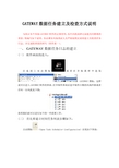
GATEWAY数据任务建立及检查方式说明为保证各个风场GATEWAY软件的正确使用,东汽风机故障记录能及时准确的查看,特编写如下说明,务必请各风场调试人员严格按照此说明建立及检查任务日志,并完成检查表的填写(附件表一)。
一、 GATEWAY数据任务日志的建立(一)软件画面的进入:在桌面上双击图标或者在开始菜单中选取GATEWAY图标,这样就可以进入GATEWAY软件的界面。
打开软件界面后选中软件左侧的风场环路或者任何一台风机见下图:接着我们就可以进行如下的一些设置工作。
(二)首先要建立时间任务列表步骤如下:点击图标(Open Task Scheduler Configuration)出现如下界面:1.点击图0-1上面的”NEW”出现如下的界面:图0-2在图0-2右侧target name:下填写名称(填写风场实际名称即可),接着就可以用鼠标点击选中,之后点击Apply就可以完成目标设定。
2.点击图0-2的Action sets选项卡,界面如下图:图0-3在图0-3中首先填写好Action set Name(填写风场实际名称即可),之后再点击出现如下图下拉选项:图0-4根据数据采集的需要选择图0-4中的如下三个选项。
选择时候就选择如下三个选项,不要多选以免在运行过程造成软件运行速度过慢不能良好工作。
具体选择选项见下图所示:图0-5选择好之后点击图0-3中的Apply即可完成Action sets选项卡设置。
3.点击图0-1的Task sets选项卡出现如下界面:图0-5接着点击图0-5的右下侧的New Task 出现如下的界面:根据要求填写该选项卡如下图所示:图0-7填写完毕后(任务目标的名称可以根据现场实际名称来定)之后点图0-7上的Apply出现如下图所示界面:图0-8首先要填写好图0-8上的Trigger name(根据实际情况填写触发名称或自定义),接着选择触发类型一般选月。
开始时间不用设置默认的就可以。

文章题目:深度解读gateway-worker 手册:从入门到精通在当今互联网时代,随着信息技术的迅猛发展,人们对于数据传输的需求也越来越高。
而在网络数据传输中,网关(gateway)和工作节点(worker)的角色变得越来越重要。
在这样的背景下,gateway-worker 手册的出现成为了解决这一问题的利器。
本文将从深度和广度两方面展开讨论,带你深入解读gateway-worker 手册,从入门到精通。
一、入门篇1. 什么是gateway-worker ?在探讨gateway-worker 手册之前,首先需要明确这一概念。
Gateway-worker 实际上是一种新型的网络数据传输架构,它将网关和工作节点结合起来,实现了高效的数据传输和处理。
它的出现,大大提高了网络传输的效率和稳定性,受到了广泛的关注和应用。
2. 安装和配置要深入了解gateway-worker 手册,就需要了解如何安装和配置。
在这一部分中,我们将详细介绍安装和配置的步骤,帮助你快速上手并开始使用gateway-worker。
3. 基本功能和用法了解gateway-worker 的基本功能和用法,是掌握它的重要一步。
我们将深入解析gateway-worker 的各项功能和用法,并结合实际案例进行演示,帮助你更好地理解和使用gateway-worker。
二、进阶篇1. 深入解读核心原理要真正精通gateway-worker,就需要深入了解其核心原理。
在这一部分中,我们将对gateway-worker 的核心原理进行解读,并分析其在网络数据传输中的应用。
2. 高级功能和拓展gateway-worker 不仅具有基本的功能,还有一些高级功能和拓展。
我们将详细介绍这些高级功能和拓展,帮助你更好地发挥gateway-worker 的潜力,满足更多的需求。
三、精通篇1. 优化与性能调优在深入使用gateway-worker 的过程中,优化和性能调优显得尤为重要。

IOTGateway使用手册(Linux V1.7)V1.7版本更新(2023.8.7)序号章节说明1 1.3增加了软件升级说明2 3.2增加了htmlview.html说明3 3.9增加了SSL通讯说明4 3.10增加了WebSocket通讯说明5 4.5增加了JS操作关系库说明6附件1增加了JS操作数据库函数1.软件安装1.1Linux系统软件下载和解压1)拷贝软件压缩包到64位Linux系统(Linux Arm64是不同的软件包),解压到某个目录下。
可以在Windows下通过PowerShell上载软件到Linux系统,使用scp命令:scp d:\IOTGateway.zip************.10.13:/home/Downloads解压缩命令:unzip IOTGateway.zip-d IOTGateway2)进入解压后的目录下对IOTGateway文件赋予可执行权限,执行下列命令。
chmod+x IOTGateway1.2启动运行1)Linux系统在终端中输入./IOTGateway启动程序从上图的显示可以看到Web服务运行在8080端口,按Ctrl+C停止运行,WebAPI 路径:swagger/index.html(一般建议关闭)2)修改Web服务端口的方法打开appsettings.json文件urls是Web服务绑定端口设置,多个地址使用分号分隔修改ProjectReadOnly为true,可以禁止项目编辑修改Html5ReadOnly为true,可以禁止H5画面保存MaxTags,设置非0时,授权变量数大于设置时status.html显示的授权点数会以无限点版本显示CorsPolicy是跨域访问设置AllowedHosts是允许访问的地址设置3)进入管理后台系统http://ip:8080/admin默认管理员:admin admin@admin用于系统配置的超级管理员:sysadmin IOTGateway点击系统配置,进入配置界面根据需要进行参数设置,点击启动按钮,启动系统运行。

WTScada Gateway使用手册v2.10WTScada Gateway软件是FScada软件的升级版本,包括数据采集和网页呈现功能,项目配置存储在关系数据库中,采用JSON格式存储,驱动配置支持在线修改和删除,支持多数据库历史、报表归档,操作便捷性和易用性比FScada有了较大提升,特别适用于MES数据采集、信息化项目。
WTScada Gateway大部分功能和驱动已经可以在Linux系统下运行(使用Windows版本组态环境进行项目配置)。
WTScada Gateway包含32位和64位Windows版本。
大于5万点IO的项目建议使用64位版本,32位版本有可能会出现内存不够的情况(尤其是组态时的数据导入)。
1.配置环境WTGateway软件支持本机保存项目组态文件和使用SQLServer、MySQL存储项目文件,支持项目相互转换。
默认情况下运行Designer.exe会尝试获取版本更新,如果电脑无法连接网络时可以通过“项目”菜单下的“自动更新”菜单关闭该功能。
新建项目对话框中可以进行项目存储方式的选择,本地项目使用SQLite存储,项目文件后缀为wgt,该文件是1个SQLite3标准数据库。
SQLServer和MySQL项目的项目文件后缀为wts,该文件是1个json文本,只记录数据库信息,项目信息全部存储在关系数据库中。
(密码可以加密存储,详见附录)数据库连接字符串提供了模板,只需要修改数据库地址,名称,账号和密码就可以,1个数据库可以存储多个项目,每个项目使用独立的表名为项目文件名。
当创建SQLServer、MySQL关系库存储项目时不存在指定的表,则创建新表,添加默认配置。
wts格式的数据库项目文件也可以手动创建和修改数据库信息,用记事本软件打开项目文件进行修改内容。
上图是SQLServer数据库项目文件格式,tableName就是数据库中表的名称使用MySQL存储项目数据时要注意由于MySQL默认数据包尺寸为1M,某个驱动如果数据量大可能会出现保存失败,这时候需要修改MySQL默认数据包尺寸。

Gateway® Cloning ProtocolsThe Basics of Gateway® ReactionGateway® expression clone from a PCR productconverting your favorite cloning vectors toTOPO® TA Cloning - To Create a Gateway® Entry CloneStep One - Produce PCR productProduce PCR products using Taq polymerase and your own protocol. End thePCR reaction with a final 7 to 30 minute extension step.Step Two - Perform t he TOPO® Cloning Reaction1. Set up one of the following TOPO® Cloning reactions using the reagentsin the order shown. For electroporation, dilute Salt Solution 4-fold to prepare Dilute Salt Solution.Reagent Chemical Txn ElectroporationFresh PCR product 0.5 to 4 µl0.5 to 4 µlSalt Solution 1 µl--Dilute Salt Solution -- 1 µlSterile Water to a final volume of 5 µl t o a final volume of 5 µlTOPO® Vector 1 µl 1 µlTotal volume 6µl6µl2. Mix gently and incubate for 5 minutes at room temperature.3. Place on ice and proceed to transform One Shot® chemically competentE. coli, belowStep Three - Transform One Shot® Chemically Competent E. coli1. For each transformation, thaw one vial of One Shot® E. coli cells onice.2. Add 2 µl of the TOPO® Cloning reaction into a vial of One Shot® chemically competent E. coli and mix gently.3. Incubate on ice for 5 to 30 minutes.4. Heat-shock the cells for 30 seconds at 42°C without shaking. Immediatelytransfer the tube to ice.5. Add 250 µl of room tem perature S.O.C. Medium.6. Incubate at 37°C for 1 hour with shaking.7. Spread 10-50 µl of bacterial culture on a prewarmed LB agar plate containing100 µg/ml spectinomycin, and incubate overnight at 37°C.The Basics of Gateway® ReactionsBP ReactionCre ating a Gateway® entry clone from an att B-flanked PCR product is an easy 1 hour reaction. See below for an overview of the set-up. For more detailed information, refer to the manual.1.Add the following components to a 1.5 ml tube at room temperatureand mix:attB-PCR product (=10 ng/µl; final amount ~15-150 ng) 1-7 µlDonor vector (150 ng/µl) 1 µlTE buffer, pH 8.0 to 8 µl2.Thaw on ice the BP Clonase™ II enzyme mix for about 2 minutes. Vortexthe BP Clonase™ II enzyme mix briefly twice (2 seconds each time).3.To each sample (Step 1, above), add 2 µl of BP Clonase™ II enzymemix to the reaction and mix well by vortexing briefly twice.Microcentrifuge briefly.4.Return BP Clonase™ II enzyme mix to -20°C or -80°C storage.5.Incubate reactions at 25°C for 1 hour.6.Add 1 µl of the Proteinase K solution to each sample to terminatethe reaction. Vortex briefly. Incubate samples at 37°C for 10minutes.Transformation1.Transform 1 µl of each BP reaction into 50 µl of One Shot ® OmniMAX™ 2 T1 Phage-Resistant Cells (Catalog no. C8540-03). Incubate on ice for 30 minutes. Heat-shock cells by incubating at 42°C for 30 seconds. Add 250 µl of S.O.C. Medium and incubate at 37°C for 1 hour with shaking. Plate 20 µl and 100 µl of each transformationonto selective plates. Note: Any competent cells with atransformation efficiency of >1.0 ×10 8 transformants/µg may be used.2.Transform 1 µl of pUC19 DNA (10 ng/ml) into 50 µl of One Shot ®OmniMAX ™ 2 T1 Phage-Resistant Cells as described above. Plate 20 µl and 100 µl on LB plates containing 100 µg/ml kanamycin, or the appropriate selection marker for your donor vector.Expected ResultsAn efficient BP recombination reaction will produce >1500 colonies if the entire BP reaction is transformed and plated.LR ReactionTransferring your gen e from a Gateway® entry clone to destination vector is an easy 1 hour reaction. See below for an overview of the set-up. For more detailed information, refer to the manual.1.Add the following components to a 1.5 ml tube at room temperatureand mix:Entry clone (50-150 ng) 1-7 µlDestination vector (150 ng/µl) 1 µlTE buffer, pH 8.0 to 8 µl2.Thaw on ice the LR Clonase ™ II enzyme mix for about 2 minutes.Vortex the LR Clonase ™ II enzyme mix briefly twice (2 seconds each time).3.To each sample (Step 1, above), add 2 µl of LR Clonase ™II enzymemix to the reaction and mix well by vortexing briefly twice.Microcentrifuge briefly.4.Return LR Clonase ™ II enzyme mix to -20°C or -80°C storage.5.Incubate reactions at 25°C for 1 hour.6.Add 1 µl of the Proteinase K soluti on to each sample to terminatethe reaction. Vortex briefly. Incubate samples at 37°C for 10minutes.TransformationFollow the protocol as indicated for the BP reaction, except use the appropriate selection marker for the LB plates suited to your destination vector (typically 100 µg/ml ampicillin).Expected ResultsAn efficient LR recombination reaction will produce >5000 colonies if the entire LR reaction is transformed and plated.One Tube FormatIf you want to transfer your attB-flanked PCR product directly into an expression clone, you can easily combine the BP and LR reactions using the following protocol. This will potentially eliminate the transformation and DNA isolation of the Gateway® entry clone.1.In a 1.5 ml microcentrifuge tube, prepare the following 15 µl BPreaction:attB DNA (50-100 ng) 1.0-5.0 µlattP DNA (pDONR™vector, 150 ng/µl) 1.3 µlBP Clonase™II enzyme mix 3.0 µlTE Buffer, pH 8.0 add to a final volume of 15 µl2.Mix well by vortexing briefly and incubate at 25°C for 4 hours.Note: Depending on your needs, the length of the recombinationreaction can be extended up to 20 hours. An overnight incubationtypically yields 5 times more colonies than a 1 hour incubation.Longer incubation times are recommended for large plasmids (=10 kb) and PCR products (=5 kb).3.Remove 5 µl of the reaction to a separate tube and use this aliquotto assess the efficiency of the BP reaction (see below).4.To the remaining 10 µl reaction, add:Destination vector (150 ng/µl) 2.0 µlLR Clonase™ II enzyme mix 3.0 µlFinal volume 15 µl5.Mix well by vortexing briefly and incubate at 25°C for 2 hours.Note: Depending on your needs, the length of the recombinationreaction can be extended up to 18 hours.6.Add 2 µl of proteinase K solution. Incubate at 37°C for 10 minutes.7.Transform 50 µl of the appropriate competent E. coli with 1 µl ofthe reaction.8.Plate on LB plates containing the appropriate antibiotic to selectfor expression clones.Assessing the Efficiency of the BP Reaction1.To the 5µl aliquot obtained from “One-Tube” Protocol, Step 3,above, add 0.5 µl of proteinase K solution. Incubate at 37°C for10 minutes.2.Transform 50 µl of the appropriate competent E. coli with 1 µl ofthe reaction. Plate on LB plates containing the appropriateantibiotic to select for entry clones.Gateway® Vector ConversionConverting your favorite set of cloning vectors to Gateway® Technologyis a fairly straightforward protocol, and will ultimately allow you to streamline your cloning and expression process.To convert your cloning vector to a Gateway® destination vector, you will:1.Choose the appropriate reading frame cassette to use depending onyour needs.2.Linearize the vector you wish to convert with a restriction enzymeof choice. If you use a restriction enzyme that generates anoverhang, you will need to blunt the ends.3.Remove the 5' phosphates from the vector using calf intestinalalkaline phosphatase.4.Ligate the reading frame cassette into your vector using T4 DNAligase.5.Transform the ligation reaction into One Shot® ccdB Survival™Competent E. coli and select for transformants.6.Analyze transformants.。
Gateway® Cloning ProtocolsThe Basics of Gateway® Reaction∙BP reaction—to create a Gateway® entry clone∙LR reaction—to create a Gateway® expression clone∙One tube format—to create a Gateway® expression clone from a PCR product∙Gateway® Vector Conversion—converting your favorite cloning vectors to Gateway® TechnologyTOPO® TA Cloning - To Create a Gateway® Entry CloneStep One - Produce PCR productProduce PCR products using Taq polymerase and your own protocol. Endthe PCR reaction with a final 7 to 30 minute extension step.Step Two - Perform the TOPO® Cloning Reaction1. Set up one of the following TOPO® Cloning reactions using thereagents in the order shown. For electroporation, dilute SaltSolution 4-fold to prepare Dilute Salt Solution.Reagent Chemical Txn ElectroporationFresh PCR product0.5 to 4 µl0.5 to 4 µlSalt Solution 1 µl--Dilute SaltSolution-- 1 µlSterile Water to a final volume of 5µlto a final volume of 5µlTOPO® Vector 1 µl 1 µlTotal volume6µl6µl2. Mix gently and incubate for 5 minutes at room temperature.3. Place on ice and proceed to transform One Shot® chemically competent E. coli, belowStep Three - Transform One Shot® Chemically Competent E. coli1. For each transformation, thaw one vial of One Shot® E. coli cells on ice.2. Add 2 µl of the TOPO® Cloning reaction into a vial of One Shot® chemically competent E. coli and mix gently.3. Incubate on ice for 5 to 30 minutes.4. Heat-shock the cells for 30 seconds at 42°C without shaking. Immediatelytransfer the tube to ice.5. Add 250 µl of room temperature S.O.C. Medium.6. Incubate at 37°C for 1 hour with shaking.7. Spread 10-50 µl of bacterial culture on a prewarmed LB agar plate containing100 µg/ml spectinomycin, and incubate overnight at 37°C.The Basics of Gateway® ReactionsBP ReactionCreating a Gateway® entry clone from an att B-flanked PCR product is an easy 1 hour reaction. See below for an overview of the set-up. For more detailed information, refer to the manual.1.Add the following components to a 1.5 ml tube at roomtemperature and mix:attB-PCR product (=10 ng/µl; final amount ~15-150 ng) 1-7 µlDonor vector (150 ng/µl) 1 µlTE buffer, pH 8.0 to 8 µl2.Thaw on ice the BP Clonase™ II enzyme mix for about 2 minutes.Vortex the BP Clonase™ II enzyme mix briefly twice (2 secondseach time).3.To each sample (Step 1, above), add 2 µl of BP Clonase™ IIenzyme mix to the reaction and mix well by vortexing brieflytwice. Microcentrifuge briefly.4.Return BP Clonase™ II enzyme mix to -20°C or -80°C storage.5.Incubate reactions at 25°C for 1 hour.6.Add 1 µl of the Proteinase K solution to each sample toterminate the reaction. Vortex briefly. Incubate samples at37°C for 10 minutes.Transformation1.Transform 1 µl of each BP reaction into 50 µl of One Shot ®OmniMAX ™ 2 T1 Phage-Resistant Cells (Catalog no. C8540-03).Incubate on ice for 30 minutes. Heat-shock cells by incubatingat 42°C for 30 seconds. Add 250 µl of S.O.C. Medium andincubate at 37°C for 1 hour with shaking. Plate 20 µl and 100µl of each transformation onto selective plates. Note: Anycompetent cells with a transformation efficiency of >1.0 × 10⁸ transformants/µg may be used.2.Transform 1 µl of pUC19 DNA (10 ng/ml) into 50 µl of One Shot ®OmniMAX ™ 2 T1 Phage-Resistant Cells as described above. Plate20 µl and 100 µl on LB plates containing 100 µg/ml kanamycin,or the appropriate selection marker for your donor vector.Expected ResultsAn efficient BP recombination reaction will produce >1500 colonies if the entire BP reaction is transformed and plated.LR ReactionTransferring your gene from a Gateway® entry clone to destination vector is an easy 1 hour reaction. See below for an overview of the set-up. For more detailed information, refer to the manual.1.Add the following components to a 1.5 ml tube at roomtemperature and mix:Entry clone (50-150 ng) 1-7 µlDestination vector (150 ng/µl) 1 µlTE buffer, pH 8.0 to 8 µl2.Thaw on ice the LR Clonase ™ II enzyme mix for about 2 minutes.Vortex the LR Clonase ™ II enzyme mix briefly twice (2 secondseach time).3.To each sample (Step 1, above), add 2 µl of LR Clonase ™IIenzyme mix to the reaction and mix well by vortexing brieflytwice. Microcentrifuge briefly.4.Return LR Clonase ™ II enzyme mix to -20°C or -80°C storage.5.Incubate reactions at 25°C for 1 hour.6.Add 1 µl of the Proteinase K solution to each sample toterminate the reaction. Vortex briefly. Incubate samples at37°C for 10 minutes.TransformationFollow the protocol as indicated for the BP reaction, except use the appropriate selection marker for the LB plates suited to your destination vector (typically 100 µg/ml ampicillin).Expected ResultsAn efficient LR recombination reaction will produce >5000 colonies if the entire LR reaction is transformed and plated.One Tube FormatIf you want to transfer your attB-flanked PCR product directly into an expression clone, you can easily combine the BP and LR reactions using the following protocol. This will potentially eliminate the transformation and DNA isolation of the Gateway® entry clone.1.In a 1.5 ml microcentrifuge tube, prepare the following 15 µlBP reaction:attB DNA (50-100 ng) 1.0-5.0 µlattP DNA (pDONR™ vector, 150 ng/µl) 1.3 µlBP Clonase™ II enzyme mix 3.0 µlTE Buffer, pH 8.0 add to a final volume of 15 µl2.Mix well by vortexing briefly and incubate at 25°C for 4hours.Note: Depending on your needs, the length of the recombinationreaction can be extended up to 20 hours. An overnightincubation typically yields 5 times more colonies than a 1 hour incubation. Longer incubation times are recommended for largeplasmids (=10 kb) and PCR products (=5 kb).3.Remove 5 µl of the reaction to a separate tube and use thisaliquot to assess the efficiency of the BP reaction (seebelow).4.To the remaining 10 µl reaction, add:Destination vector (150 ng/µl) 2.0 µlLR Clonase™ II enzyme mix 3.0 µlFinal volume 15 µl5.Mix well by vortexing briefly and incubate at 25°C for 2hours.Note: Depending on your needs, the length of the recombinationreaction can be extended up to 18 hours.6.Add 2 µl of proteinase K solution. Incubate at 37°C for 10minutes.7.Transform 50 µl of the appropriate competent E. coli with 1 µlof the reaction.8.Plate on LB plates containing the appropriate antibiotic toselect for expression clones.Assessing the Efficiency of the BP Reaction1.To the 5µl aliquot obtained from “One-Tube” Protocol, Step 3,above, add 0.5 µl of proteinase K solution. Incubate at 37°Cfor 10 minutes.2.Transform 50 µl of the appropriate competent E. coli with 1 µlof the reaction. Plate on LB plates containing the appropriateantibiotic to select for entry clones.Gateway® Vector ConversionConverting your favorite set of cloning vectors to Gateway® Technology is a fairly straightforward protocol, and will ultimately allow you to streamline your cloning and expression process.To convert your cloning vector to a Gateway® destination vector, you will:1.Choose the appropriate reading frame cassette to use dependingon your needs.2.Linearize the vector you wish to convert with a restrictionenzyme of choice. If you use a restriction enzyme thatgenerates an overhang, you will need to blunt the ends.3.Remove the 5' phosphates from the vector using calf intestinalalkaline phosphatase.4.Ligate the reading frame cassette into your vector using T4 DNAligase.5.Transform the ligation reaction into One Shot® ccdB Survival™Competent E. coli and select for transformants.6.Analyze transformants.。