OM500网关远程自动更新配置手册
- 格式:doc
- 大小:370.43 KB
- 文档页数:14
第1章策略路由配置1.1 策略路由简介与单纯依照IP报文的目的地址查找路由表进行转发不同,策略路由是一种依据用户制定的策略进行路由选择的机制,可应用于多ISP出口流量分担等目的。
本系统的策略路由支持基于到达报文的源地址、端口号等信息,灵活地指定路由。
1.2 策略路由的配置Eudemon500/1000的策略路由是在安全区域上实现的。
通过trafficclassifier、traffic behavior、qos policy、qos apply policy等命令支持基于域的策略流量分担。
策略路由配置包括:●定义ACL规则●定义类和流分类规则●定义策略路由动作●定义策略●使用策略此外还可以在流行为中配置流量监管CAR(Committed Access Rate)特性。
1.2.1 定义ACL规则在系统视图下,使用acl命令定义访问控制列表,并进入ACL视图,在该ACL视图中使用rule命令定义一组规则。
具体请参考本手册“安全防范”部分。
1.2.2 定义类和流分类规则1. 定义类并进入类视图在系统视图下,使用traffic classifier命令定义类,并进入类视图。
表1-1定义一个类并进入类视图2. 定义流分类规则在类视图下定义一组流分类规则。
表1-2定义或删除ACL匹配规则1.2.3 定义策略路由动作1. 定义流行为并进入流行为视图在系统视图下,使用traffic behavior命令定义流的动作,并进入流行为视图。
表1-3定义一个流行为并进入流行为视图behavior-name:流行为名,不允许为系统预定义流行为。
2. 配置重新指定下一跳路由在流行为中使用remark ip-nexthop命令定义策略路由动作。
请在流行为视图下进行下列配置。
表1-4配置重新指定下一跳路由1.2.4 定义策略1. 定义策略并进入策略视图在系统视图下,使用qos policy命令定义策略并进入策略视图。
表1-5定义策略并进入策略视图如果某安全区域应用了该策略,则不允许删除该策略,需要在应用的安全区域上取消对该策略的应用,然后再使用undo qos policy删除该策略。

Configuration Note ContentsTable of Contents1Introduction (7)2Backing up Configuration (9)2.1Backing up Device Configuration through Web Interface (9)2.2Backing up Device Configuration through CLI (10)2.2.1Backing Up Configuration on a Data-enabled Device (10)2.2.2Backing Up Configuration on a Voice-enabled Device (10)2.3Backing Up EMS Configuration Before Upgrade (12)2.3.1Changing Scheduled Backup Time (12)2.3.2Collecting EMS Logs (13)3Restoring Configuration (15)3.1Restoring Device Configuration through Web Interface (15)3.2Restoring Device Configuration through CLI (16)3.2.1Restoring Configuration on a Data-enabled Device (16)3.2.2Restoring Configuration on a Voice-enabled Device (16)3.3Restoring EMS Configuration After Upgrade (18)Version 7.2 3 Mediant Series Gateways & SBCsConfiguration File Backup & Restore ProcedureThis page is intentionally left blank.Configuration Note 4 Document #: LTRT-39624Configuration Note NoticesNoticeInformation contained in this document is believed to be accurate and reliable at the time of printing. However, due to ongoing product improvements and revisions, AudioCodes cannot guarantee accuracy of printed material after the Date Published nor can it accept responsibility for errors or omissions. Before consulting this document, check the corresponding Release Notes regarding feature preconditions and/or specific support in this release. In cases where there are discrepancies between this document and the Release Notes, the information in the Release Notes supersedes that in this document. Updates to this document and other documents as well as software files can be downloaded by registered customers at /downloads.© Copyright 2017 AudioCodes Ltd. All rights reserved.This document is subject to change without notice.Date Published: February-08-2017Trademarks©2017 AudioCodes Ltd. All rights reserved. AudioCodes, AC, HD VoIP, HD VoIP SoundsBetter, IPmedia, Mediant, MediaPack, What’s Inside Matters, OSN, SmartTAP, UserManagement Pack, VMAS, VoIPerfect, VoIPerfectHD, Your Gateway To VoIP, 3GX,VocaNom, AudioCodes One Voice and CloudBond are trademarks or registeredtrademarks of AudioCodes Limited. All other products or trademarks are property of theirrespective owners. Product specifications are subject to change without notice.WEEE EU DirectivePursuant to the WEEE EU Directive, electronic and electrical waste must not be disposedof with unsorted waste. Please contact your local recycling authority for disposal of thisproduct.Customer SupportCustomer technical support and services are provided by AudioCodes or by an authorizedAudioCodes Service Partner. For more information on how to buy technical support forAudioCodes products and for contact information, please visit our Web site at/support.Abbreviations and TerminologyEach abbreviation, unless widely used, is spelled out in full when first used.Document Revision RecordVersion 7.2 5 Mediant Series Gateways & SBCsConfiguration File Backup & Restore ProcedureDocumentation FeedbackAudioCodes continually strives to produce high quality documentation. If you have anycomments (suggestions or errors) regarding this document, please fill out theDocumentation Feedback form on our Web site at /downloads.Configuration Note 6 Document #: LTRT-39624Configuration Note 1. Introduction1 IntroductionThis document describes the procedures for backing up and restoring your device'sconfiguration settings.It is important to back up your configuration on a regular basis in case you need to restoreconfiguration if, for example, any of the following scenarios occurs:⏹Your device has a hardware fault that requires it to be replaced entirely.⏹ A hardware component on the device is faulty (e.g., CPU).⏹Firmware upgrade failure⏹Undesired configuration upgrade or failure.Note:•It is your responsibility to save the backup configuration files after every configurationchange made on the device.•It is your responsibility to back up your existing configuration and firmware files to a safe location on your network before upgrading the device.Version 7.2 7 Mediant Series Gateways & SBCsConfiguration File Backup & Restore ProcedureThis page is intentionally left blank.Configuration Note 8 Document #: LTRT-39624Version 7.2 9 Mediant Series Gateways & SBCs Configuration Note2. Backing up Configuration 2 Backing up ConfigurationYou can save a copy of the device's current configuration settings as a file on a local PC server. This can be used as a backup file for your configuration. The saved file includes only parameters that were modified and parameters with other than default values.You can also save (create) the current configuration as a configuration file on the device's flash memory and send it to a user-defined URL of a remote server (TFTP or HTTP/S) or to a USB device. The configuration settings in the file are based only on CLI commands. For more information, refer to the CLI Reference Manual .This chapter describes how to backup the configuration through one of the following management interfaces:⏹Web interface (see Section 2.1) ⏹CLI (see Section 2.2) ⏹EMS (see Section 2.3)Note:• Make sure you have a backup copy of all auxiliary files (e.g., CPT and Dial Plan files) before you upload them to the device.• If you do not have a backup of the device’s cmp file on your PC, you must open a service request to receive it.• In case of outage due to hardware upgrade or replacement or disaster, use theBootP tool to connect directly to the device from a PC. A trained technician should be present on the local site for performing this task.• If you do not have the BootP tool on your site, open a service request it to receive it.2.1Backing up Device Configuration through WebInterfaceThe Web interface allows you to back up the device's configuration as an ini file or a CLI-based file (CLI script) in a folder on the PC client running the Web interface.To back up the configuration:1. Open the Configuration File page:•Toolbar: From the Actions drop-down menu, choose Configuration File . • Navigation tree: Setup menu > Administration tab > Maintenance folder >Configuration File .Figure 2-1: Backing up Configuration through Web InterfaceConfiguration Note 10 Document #: LTRT-39624 Configuration File Backup & Restore Procedure2. Click one of the following buttons:•Save INI File: saves the configuration as an ini file. • Save CLI Script File: saves the configuration as a CLI-based file.2.2 Backing up Device Configuration through CLIThe CLI allows you to back up the device's configuration as a CLI-based file (CLI command settings). You can back up the CLI-based file to any of the following locations:⏹Remote server (HTTP, HTTPS or TFTP) ⏹USB stickNote: The USB stick is only applicable to devices that provide USB support.The procedures below describes how to back up the devices configuration using CLI on a data-enabled and voice-enabled device. 2.2.1 Backing Up Configuration on a Data-enabled DeviceThis section describes how to back up the devices configuration on a data-enabled device. To back up the configuration using CLI on a data-enabled device:1.Establish a CLI serial connection with the device (e.g., Telnet). 2. Log in to the CLI.Username: AdminPassword: < Password >3. Access the Enable mode.> enablePassword: < Enable mode password >4.Enter the following command:# copy cli-script to { < URL > | usb :///< File Name > }source data interface <interface type> <interface id> 2.2.2 Backing Up Configuration on a Voice-enabled DeviceThis section describes how to back up the devices configuration on a voice-enabled device.To back up the configuration using CLI on a voice-enabled device:1.Establish a CLI serial connection with the device (e.g., Telnet). 2.Log in to the CLI.Username: AdminPassword: < Password >3. Access the Enable mode.> enablePassword: < Enable mode password >Configuration Note 2. Backing up Configuration4. Enter the following command:# copy cli-script to { < URL > | usb:///< File Name > }Arguments DescriptionURL When copying to a URL, the destination URL can be one of thefollowing:•HTTP•HTTPS•TFTPusb:///< File Name> Backs up the configuration to the USB stick connected to the device.source Specifies the source CPU to copy from (default data).interface Specifies the source interface to bind to.source-address Specifies the source address.Interface Type Interface ID gigabitethernet GigabitEthernet interface slot andport (VLAN ID is optional)[SLOT/PORT.VLANID] cellular Cellular interface ID 0/0Gr-e Tunnel GRE ID [1-255]ipip Tunnel IPIP ID [1-255]l2tp L2TP ID [0-99]pppoe PPPoE interface ID [1-3]pptp PPTP ID [0-99]vlan Vlan ID [1-3999]loopback Loopback ID [1-5]bvi Bridge interface [1-255]Version 7.2 11 Mediant Series Gateways & SBCsConfiguration Note 12 Document #: LTRT-39624Configuration File Backup & Restore Procedure2.3 Backing Up EMS Configuration Before UpgradeBefore upgrading the EMS server, it is highly recommended to backup the EMS server database. There are two main backup processes that run on the EMS server: ⏹Weekly backup: runs once a week at a pre-configured date & time (default is Saturday 02:00). In this process, the whole database is backed up into several “RMAN” files that are located in /data/NBIF/emsBackup/RmanBackup directory. In addition, many other configuration and software files are backed up to a TAR file in the /data/NBIF/emsBackup directory. In general, this TAR file contains the entire/data/NBIF directory’s content (except 'emsBackup' directory), EMS Software Manager content and server_xxx directory’s content.To change the weekly backup’s time and date, see Section 2.3.1 below. ⏹Daily backup: runs daily except on the scheduled week day (see above). The daily backup process backs up the last 24 hours. There are no changes in the TAR file in this process.Warning: The Backup process does not backup configurations performed using EMS Server Manager, such as networking and security.It is highly recommended to maintain all backup files on an external machine.These files can be transferred outside the server directly from their default location by SCP or SFTP client using 'acems' user. These backup files are as follows: ⏹ /data/NBIF/emsBackup/emsServerBackup_<time&date>.tar file⏹All files in /data/NBIF/emsBackup/RmanBackup directory (including control.ctl and init.ora files)2.3.1 Changing Scheduled Backup TimeThis step describes how to reschedule the backup time.To reschedule backup time:1. From the Application Maintenance menu, choose Change Schedule Backup Time .2. Choose the day of the week that you wish to perform the backup.3. Copy all files in /data/NBIF/emsBackup/RmanBackup/ directory to an external machine.4.Copy /data/NBIF/emsBackup/emsServerBackup_<time&date>.tar file to an external machine.Where <time&date> is only an example; replace this path with your filename.Configuration Note 2. Backing up Configuration2.3.2 Collecting EMS LogsIt is recommended to collect EMS logs before upgrading or re-configuring the EMS server.This enables you to restore the MG treeTo collect logs:1. From the EMS Server Management root menu, choose Collect Logs, and then pressEnter; the EMS server commences the log collection process:Figure 2-2: EMS Server Manager – Collect LogsThis process can take a few minutes. Once the file generation has completed, a messageis displayed on the screen informing you that a Diagnostic tar file has been created and thelocation of the tar file:Figure 2-3: TAR File LocationVersion 7.2 13 Mediant Series Gateways & SBCsConfiguration File Backup & Restore Procedure2. The MGs Topology list containing all the devices in the MG Tree is found in thefollowing file:/data/NBIF/topology/MGsTopologyList.csvAn example of this file is shown in the figure below:Figure 2-4: MGs Topology ListConfiguration Note 14 Document #: LTRT-39624Version 7.2 15 Mediant Series Gateways & SBCsConfiguration Note3. Restoring Configuration 3 Restoring ConfigurationYou can restore the configuration through one of the following management interfaces: ⏹ Web interface (see below) ⏹ CLI (see Section 3.2) ⏹EMS (see Section 3.3)Warning:• When restoring an ini file, the device resets for the settings to take effect. • When loading an ini file using the Configuration File page, parameters notincluded in the ini file are reset to default settings.3.1Restoring Device Configuration through Web InterfaceThe Web interface allows you to restore the device's configuration as an ini file or aCLI-based file (CLI script) from the folder on the PC client running the Web interface, by uploading an ini file or CLI-based file.Warning: When restoring an ini file using the Configuration File page, parameters excluded from the ini file return to default settings . If you want to keep the device's current configuration settings and apply the settings specified in the ini file, load the file through the Auxiliary Files page.To restore the configuration file:1.Open the Configuration File page: • Toolbar: From the Actions drop-down menu, choose Configuration File . •Navigation tree:Setupmenu > Administration tab > Maintenance folder > Configuration File .Figure 3-1: Loading INI File using Configuration File Page2.Click one of the following buttons: • Load INI File: restores the configuration from the ini file.•Load CLI Script File: restores the configuration from the CLI-based file.Configuration Note 16 Document #: LTRT-39624Configuration File Backup & Restore Procedure3.2 Restoring Device Configuration through CLIThe CLI allows you to restore the device's configuration as a CLI-based file (CLI command settings). You can restore the CLI-based file from any of the following locations: ⏹ Remote server (HTTP, HTTPS or TFTP) ⏹ USB stickNote: The USB stick is only applicable to devices that provide USB support.The procedures below describe how to restore the devices configuration using CLI on the following platforms: ⏹ Data-enabled device (see Section 3.2.1) ⏹Voice-enabled device (see Section 3.2.2) 3.2.1 Restoring Configuration on a Data-enabled DeviceThis section describes how to restore the devices configuration on a data-enabled device.To restore the configuration using CLI on a data-enabled device:1. Establish a CLI serial connection with the device (e.g., Telnet).2.Log in to the CLI. Username: AdminPassword: < Password >3.Access the Enable mode. > enablePassword: < Enable mode password >4.Enter the following command:# copy cli-script from { < URL > | usb :///< File Name > }source data interface <interface type> <interface id>3.2.2 Restoring Configuration on a Voice-enabled DeviceThis section describes how to restore the devices configuration on a voice-enabled device.To restore the configuration using CLI on a voice-enabled device:1. Establish a CLI serial connection with the device (e.g., Telnet).2.Log in to the CLI. Username: AdminPassword: < Password >3.Access the Enable mode. > enablePassword: < Enable mode password >Configuration Note 3. Restoring Configuration4. Enter the following command:# copy cli-script from { < URL > | usb:///< File Name > }Arguments DescriptionURL When copying to a URL, the destination URL can be one of thefollowing:•HTTP•HTTPS•TFTPusb:///< File Name> Backs up the configuration to the USB stick connected to the device.source Specifies the source CPU to copy from (default data).interface Specifies the source interface to bind to.source-address Specifies the source address.Interface Type Interface ID gigabitethernet GigabitEthernet interface slot andport (VLAN ID is optional)[SLOT/PORT.VLANID] cellular Cellular interface ID 0/0Gr-e Tunnel GRE ID [1-255]ipip Tunnel IPIP ID [1-255]l2tp L2TP ID [0-99]pppoe PPPoE interface ID [1-3]pptp PPTP ID [0-99]vlan Vlan ID [1-3999]loopback Loopback ID [1-5]bvi Bridge interface [1-255]Version 7.2 17 Mediant Series Gateways & SBCsConfiguration File Backup & Restore Procedure3.3 Restoring EMS Configuration After UpgradeThis section describes how to restore the EMS server after it has been upgraded. This canbe done on the original machine from which the backup files were created or on any othermachine.Note:•If you’re running the restore process on a different machine, its disk sizeshould be the same as the original machine from which the backup files were Array taken.•Restore actions can be performed only with backup files which werepreviously created in the same EMS version.•If you are restoring to a new machine, make sure that you have purchased anew license file machine ID. AudioCodes customer support will assist you toobtain a new license prior to the restore process.To restore the EMS server:1. Install (or upgrade) EMS to the same version from which the backup files werecreated. The Linux version must also be identical between the source and targetmachines.2. Use the EMS Server Management utility to perform all the requiredconfigurations, such as Networking and Security, as was previously configuredon the source machine.3. Make sure all server processes are up in EMS Server Manager / Status menuand the server functions properly.4. Copy all backup files to /data/NBIF directory by SCP or SFTP client using the'acems' user.5. In EMS Server Manager, go to the Application Maintenance menu and select theRestore option.6. Follow the instructions during the process.7. After the restore process has completed, you will be asked to reboot themachine.8. If you installed custom certificates prior to the restore, you must reinstall thesecertificates.Configuration Note 18 Document #: LTRT-39624Configuration Note 3. Restoring ConfigurationThis page is intentionally left blank.Version 7.2 19 Mediant Series Gateways & SBCsInternational HeadquartersContact us: /info Website: Document #: LTRT-39624。
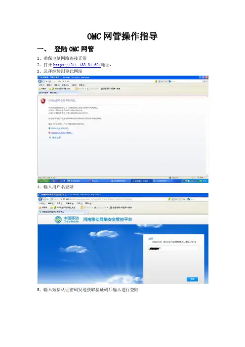
OMC网管操作指导一、登陆OMC网管1、确保电脑网络连接正常2、打开https://211.138.31.62/地址,3、选择继续浏览此网站4、输入用户名登陆5、输入短信认证密码发送获取验证码后输入进行登陆6、登陆后如下图,根据要操作的网络选择相应的服务器,以LTE为例,选择HWTD_ONMCR-10 服务器地址10.87.84.34、二、登陆LTE网管后如下界面1、网管工具栏包括系统、监控、维护、拓扑、性能、安全、配置、软件、CME、许可证、SON、窗口、帮助等选项,每个选型里边都包含相应的子菜单。
图标为常用的功能选项。
下边以常用的功能进行说明:三、 eNodeB MML常用命令在网络规划和优化工作中,对单个eNodeB进行远端操作维护的情况较少,一般都可以在M2000下对eNodeB进行相关的操作。
不过对eNodeB进行的数据查询、数据记录、参数修改等工作,在eNodeB侧最常用的方法是在eNodeB操作维护系统下使用MML命令。
至于eNodeB中比较齐全的MML命令,可以通过eNodeB的操作维护中Search功能中的关键词进行查询。
在Keyword一栏中输入所需要查询的关键词,键入回车键即可显示相关的MML命令。
下面列出了网规网优常用的几类MML命令进行整理和分类:表1 网规网优机房常用eNodeB MML操作命令集四、机房操作命名解析1、MML命令界面2、常用命令解析DSP 对象操作的命令cell 需要操作的对象DSP CELL:LOCALCELLID=0;执行操作。
类似DSP常用的命令,包括有:DSP 显示LST 查看MOD 修改SET 设置ADD添加RMV 删除BLK 锁住UBL 解锁DEA 去激活ACT 激活3、查询基站配置信息:LSTENODEB4、修改基站:MOD ENODEB5、查询小区动态参数:DSP CELL6、查询小区静态参数LST CELL7、修改小区MOD CELL8、查询PDSCH配置信息(参考信号功率):LST PDSCHCFG:;9、PDSCH配置信息(参考信号功率) MOD PDSCHCFG10、查询活动告警:LST ALMAF11、查看跟踪区域配置信息:LST CNOPERATORTA12、查询eNodeB加密算法优先级配置:LST ENODEBCIPHERCAP13、查询eNodeB完整性保护算法优先级:LST ENODEBINTEGRITYCAP14、查询小区模拟负载控制:LST CELLSIMULOAD15、查询PDCCH算法:LST CELLPDCCHALGO16、查询EUTRAN同频邻区关系:LST EUTRANINTRAFREQNCELL17、查询EUTRAN外部小区:LST EUTRANEXTERNALCELL18、添加外部邻区关系19、添加同频邻区关系20、删除EUTRAN同频邻区关系21、删除EUTRAN外部小区22、查询基站数据业务用户数:DSP S1INTERFACE五、信令跟踪1、信令跟踪2、S1标准信令跟踪3、LTE虚用户跟踪当被跟踪用户所在eNodeB未知,且MME不是由本OMC920管理时,建立虚用户跟踪。

认证计费管理专家Product Mode: 安朗多功能网关控制软件Series 操作手册广州安朗通信科技有限公司Guangzhou Amnoon Communication Tech. Co.,Ltd.目录1.系统简介AM-MNG系列综合接入网关是适用于商业应用(学校、商场、医院)的无线Portal认证环境。
以及厂区宿舍、小型ISP运营等Portal 认证及PPPoE认证环境。
本手册是针对AMG-MNG系列产品,如果系统有更新改动,请参考更新的操作手册。
2.登录和退出安朗多功能网关控制软件的认证计费管理平台采用B/S管理结构,管理员接入eth0,只需打开浏览器,输入如下形式的URL:http://192.168.1.11:8080/其中192.168.1.11是默认的eth0口地址,即出现管理员的登录界面,如下图所示:注:如果是在LAN口上访问设备,请输入如下形式的URL:http://1.1.1.1:8080/ 输入管理员的帐号和密码(默认admin/admin),进入系统,如下图:在页面右上角,有“退出”按钮,点击后即退出系统。
3.功能配置3.1. 系统查看3.1.1.主机状态显示主机相关信息,包括当前时间、CPU空闲、内存、硬件型号、软件版本号、端口连接情况以及系统重启快捷按钮。
如果显示时间和现实时间不相符,也可手动修改,点击“修改时间”按钮,进入时间修改页面修改即可。
3.1.2.日志查看只填写“操作时间段”时,会显示此段时间内,所有的操作人,以及对应的精确操作时间、IP地址和操作内容;进一步填写“操作内容”时,就会显示此段时间内某项操作的操作人、精确操作时间和IP地址。
3.1.3.在线用户查看系统的认证后的在线用户。
查询方式:用户账户、用户IP、接入服务器、MAC地址。
查询后会显示出此用户的账号名、MAC地址、接入的设备IP、接入的端口、用户的IP、上线的时间等。
可根据需求进行“强制下线”和“删除”操作。


5 GHz 500米电梯网桥Web操作手册法律声明版权所有©杭州海康威视数字技术股份有限公司2022。
保留一切权利。
本手册的任何部分,包括文字、图片、图形等均归属于杭州海康威视数字技术股份有限公司或其关联公司(以下简称“海康威视”)。
未经书面许可,任何单位或个人不得以任何方式摘录、复制、翻译、修改本手册的全部或部分。
除非另有约定,海康威视不对本手册提供任何明示或默示的声明或保证。
关于本产品本手册描述的产品仅供中国大陆地区销售和使用。
本产品只能在购买地所在国家或地区享受售后服务及维保方案。
关于本手册本手册仅作为相关产品的指导说明,可能与实际产品存在差异,请以实物为准。
因产品版本升级或其他需要,海康威视可能对本手册进行更新,如您需要最新版手册,请您登录海康威视官网查阅()。
海康威视建议您在专业人员的指导下使用本手册。
商标声明●为海康威视的注册商标。
●本手册涉及的其他商标由其所有人各自拥有。
责任声明●在法律允许的最大范围内,本手册以及所描述的产品(包含其硬件、软件、固件等)均“按照现状”提供,可能存在瑕疵或错误。
海康威视不提供任何形式的明示或默示保证,包括但不限于适销性、质量满意度、适合特定目的等保证;亦不对使用本手册或使用海康威视产品导致的任何特殊、附带、偶然或间接的损害进行赔偿,包括但不限于商业利润损失、系统故障、数据或文档丢失产生的损失。
●您知悉互联网的开放性特点,您将产品接入互联网可能存在网络攻击、黑客攻击、病毒感染等风险,海康威视不对因此造成的产品工作异常、信息泄露等问题承担责任,但海康威视将及时为您提供产品相关技术支持。
●使用本产品时,请您严格遵循适用的法律法规,避免侵犯第三方权利,包括但不限于公开权、知识产权、数据权利或其他隐私权。
您亦不得将本产品用于大规模杀伤性武器、生化武器、核爆炸或任何不安全的核能利用或侵犯人权的用途。
●如本手册内容与适用的法律相冲突,则以法律规定为准。
前言本节内容的目的是确保用户通过本手册能够正确使用产品,以避免操作中的危险或财产损失。

多功能Portal网关UAC500配置说明2014/8/11V 1.2目录1. 系统管理 (2)1.1 系统管理方式 (2)2. 网络管理 (4)2.1 IP设置 (4)2.2 DHCP服务器配置 (4)2.3 路由配置 (5)2.4 端口映射 (6)2.5 外网直通和内网直通 (6)3. 用户管理 (7)3.1 创建用户 (7)3.2 创建用户组 (8)3.3 账户查询 (9)3.4 导入和导出用户 (9)3.4.1 批量导入用户 (9)3.5 导出用户 (10)3.6 删除用户 (10)4. Portal管理 (11)4.1 本地portal (11)4.2 外部AAA服务器Portal (15)4.3 加入UACloud (17)5. 微信认证 (19)6. 系统维护 (24)6.1 系统升级 (24)6.2 配置备份和恢复 (25)6.2.1 配置备份 (25)6.2.2 配置恢复 (25)1.系统管理1.1 系统管理方式UAC500支持通过浏览器进行直观的图像界面管理,也支持使用console来进行命令行的管理。
由于通过console管理相对复杂,这里以网页管理方式来进行说明。
UAC500拥有1个console口,6个以太网接口。
默认情况下,第一个以太网接口为WAN口,其他接口为LAN 口。
由于LAN口默认开启了认证,因此可以通过WAN口来进行管理。
WAN口的默认IP地址为192.168.1.11。
要对UAC500进行管理,请将电脑的有线网卡IP地址设置为192.168.1.0网段,然后连接到第一个以太网接口(eth0),这时候打开浏览器,输入http://192.168.1.11:8080就能访问UAC500的配置页面了。
默认的用户名和密码为admin/admin。
此外,也可以将PC连接到第二个以太网口(eth1),默认情况下eth1开启了DHCP,当获取到IP之后,是上不了外网的。

Installation InstructionsOriginal InstructionsCommunication Firmware in PowerMonitor 500 Units with EtherNet/IP Network CommunicationCatalog Numbers 1420-V1-ENT, 1420-V2-ENT, 1420-V1A-ENT, 1420-V2A-ENT, 1420-V1P-ENT, 1420-V2P-ENTIntroductionThis document describes the procedure to update Ethernet network communication firmware in the 1420-V1-ENT, 1420-V2-ENT,1420-V1A-ENT, 1420-V1P-ENT, 1420-V2A-ENT, and 1420-V2P-ENT model PowerMonitor™ 500 units. Read and follow the procedure outlined in this document carefully.Topic Page Introduction 1Download the Firmware 2Prepare the PowerMonitor 500 Unit 4Install the Firmware 5Troubleshooting 8Additional Resources82Rockwell Automation Publication 1420-IN001A-EN-P - May 2016Communication Firmware in PowerMonitor 500 Units with EtherNet/IP Network CommunicationDownload the FirmwarePowerMonitor 500 firmware and release notes are available online with the Product Compatibility and Download Center. Follow these steps to download the firmware.1.The PowerMonitor 500 unit Ethernet communication firmware is found at the following link:/Pages/MultiProductDownload.aspx?crumb=1122.Enter ‘1420’ in the Product Search window.3.Select 1420-Vx-ENT, PowerMonitor 500 and select the Ethernet firmware version that you want to install.4.From the Selections tab, click Downloads.5.Under Downloads, click .Communication Firmware in PowerMonitor 500 Units with EtherNet/IP Network Communication6.Click the checkbox for the firmware update link.One item is added to the Download Cart.7.Click Close in the Available Downloads dialog box.8.Click Download Cart.9.Follow the prompts to complete the download.Rockwell Automation Publication 1420-IN001A-EN-P - May 201634Rockwell Automation Publication 1420-IN001A-EN-P - May 2016Communication Firmware in PowerMonitor 500 Units with EtherNet/IP Network CommunicationPrepare the PowerMonitor 500 UnitT o prepare the PowerMonitor 500 unit for the firmware installation, follow these steps.1.Configure a personal computer with a fixed IP address of 192.168.1.x (where x ≠ 10) on its wired Ethernet network port.2.Make a note of the existing PowerMonitor 500 unit Ethernet network IP address and Modbus/TCP port.3.Enter programming mode through the front display of the PowerMonitor 500 and navigate to the Ethernet menu (menu page 130).4.Configure the PowerMonitor 500 to use a fixed IP address of 192.168.1.10 (required) and port 502 for Modbus/TCP.See Chapter 3 of the PowerMonitor 500 Unit user manual, publication 1420-UM001, for more information on how to configure the Ethernet settings of the PowerMonitor 500 unit.5.Connect the PowerMonitor 500 unit to the personal computer Ethernet port by using a crossover or straight-through (1) patch cable. The connection must be point-to-point without a router or any other network devices.(1)A straight-through cable works if the NIC on your personal computer supports Auto MDI-X (required on Gigabit Ethernet NICs).Rockwell Automation Publication 1420-IN001A-EN-P - May 20165Communication Firmware in PowerMonitor 500 Units with EtherNet/IP Network CommunicationInstall the FirmwareT o install the firmware, follow these steps.1.Extract files from the firmware Zip archive to a folder.unch the AutoBootLoader.exe program.3.In the Ethernet/IP tab, set the IP Device to 192.168.1.10.The default Port Device 502 is correct.4.Click Start Boot Loader.The Log field displays ‘Enabled Boot Loader’.5.Close the Auto Boot Loader program.6.W ait approximately 60 seconds for the Ethernet communications module to restart.7.Open the Windows command prompt and ping 192.168.1.10 to verify the communication module has rebooted.IMPORTANTThe default IP Device address is 192.168.1.1. Each time the Auto Boot Loader program is opened, the default IP Device address must be changed to 192.168.1.10.IMPORTANTWhile the boot loader is active in the PowerMonitor 500 unit, the unit does not respond to EtherNet/IP or Modbus network messages until the remainingprocedures are completed. After the unit reboots, it responds to a command-line Ping to 192.168.1.10.6Rockwell Automation Publication 1420-IN001A-EN-P - May 2016Communication Firmware in PowerMonitor 500 Units with EtherNet/IP Network Communication8.Open Internet Explorer or Mozilla Firefox (not Google Chrome) and browse to http://192.168.1.10.9.Enter ‘user’ as the User ID and ‘user’ as the Password, then click Login.10.Click Browse.11.Select the firmware file to install and click Open.12.Once the firmware file is selected, click Upload.Rockwell Automation Publication 1420-IN001A-EN-P - May 20167Communication Firmware in PowerMonitor 500 Units with EtherNet/IP Network Communication13.When the File Upload Done! message appears, click Reset MCU.14.W ait approximately 15 seconds, and then close the internet unch the Auto Boot Loader again.16.In the Ethernet/IP tab, set the IP Device to 192.168.1.10.The default Port Device 502 is correct.17.Click Confirm Firmware.The Log field displays ‘Enabled Boot Loader’.This step is required to complete the firmware update process by using the Auto Boot Loader program, but the firmware revision must be verified in the next step.18.Verify the new Ethernet firmware revision by using RSLinx® Classic and viewing the Device Properties of the PowerMonitor 500 inRSWho.19.Once you have confirmed that the firmware has updated successfully, power cycle the unit.20.Y ou can now change the PowerMonitor 500 unit Ethernet IP address back to its original value as noted in Prepare the PowerMonitor 500Unit , step 2.IMPORTANT If the web browser displays an error, refresh the web page. It can be necessary to repeat steps 9 …12.IMPORTANTThe default IP Device address is 192.168.1.1. Each time the Auto Boot Loader program is opened, the default IP Device address must be changed to192.168.1.10.Allen-Bradley, PowerMonitor, RSLinx, Rockwell Automation, and Rockwell Software are trademarks of Rockwell Automation, Inc.Trademarks not belonging to Rockwell Automation are property of their respective companies.Rockwell Otomasyon Ticaret A.Ş., Kar Plaza İş Merkezi E Blok Kat:6 34752 İçerenköy, İstanbul, T el: +90 (216) 5698400Rockwell Automation maintains current product environmental information on its website at/rockwellautomation/about-us/sustainability-ethics/product-environmental-compliance.page .Publication 1420-IN001A-EN-P - May 2016Copyright © 2016 Rockwell Automation, Inc. All rights reserved. Printed in the U.S.A.TroubleshootingThis section helps troubleshoot issues that can arise while updating the Ethernet firmware of the PowerMonitor 500 firmware.Additional ResourcesThese documents contain additional information concerning related products from Rockwell Automation.Y ou can view or download publications at /global/literature-library/overview.page . T o order paper copies of technical documentation, contact your local Allen-Bradley distributor or Rockwell Automation sales representative.Rockwell Automation SupportFor technical support, visit /support/overview.page .DescriptionPossible CauseCorrective ActionAuto Boot Loader displays ‘Socket Connection timeout - no host’.1.The incorrect IP address is set in the Auto Boot Loader program.Set the IP Device address to 192.168.1.10 in the Auto Boot Loader program.2.The PM500 is not configured to the IP address of 192.168.1.10.Configure the PM500 to the fixed IP address 192.168.1.10.3.Boot mode has already been enabled.Open Internet Explorer or Mozilla Firefox, browse to http://192.168.1.10, and proceed with the firmware update procedure.4.The PowerMonitor 500 has stopped communicating.Power cycle the PowerMonitor 500 unitAuto Boot Loader displays ‘Socket Connection timeout’.1.Boot mode has already been enabled.Open Internet Explorer or Mozilla Firefox, browse to http://192.168.1.10, and proceed with the firmware update procedure.ResourceDescriptionPowerMonitor 500 Unit User Manual, publication 1420-UM001Provides installation instructions, wiring diagrams, configuration, and specifications for PowerMonitor 500 units.Industrial Automation Wiring and Grounding Guidelines, publication 1770-4.1 Provides general guidelines for installing a Rockwell Automation industrial system.Product Certifications website,/global/certification/overview.pageProvides declarations of conformity, certificates, and other certification details.。
目录第1章基本配置 (1)1.2操作终端设置及系统登录 (3)1.2.1 本地串口终端配置 (3)1.2.2 Telnet终端配置 (5)1.3 基本配置 (11)1.3.1 切换语言 (11)1.3.2 开启交互 (12)1.3.3 设置系统时间 (12)1.3.4 设置操作用户 (13)1.3.5 确认单板正常工作 (16)1.3.6 确认单板版本正确 (19)1.3.7 确认AIC板工作正常 (20)1.3.8 确认外网口地址已配置 (22)1.4 系统时钟配置 (25)1.4.1 系统时钟简介 (25)1.4.2 系统时钟配置举例 (25)1.4.3 时钟配置实例 (26)1.5 流控管理 (37)1.5.1 修改速率表 (37)1.5.2 建立流量索引 (40)1.5.3 流控参数说明 (45)1.5.4 流量配置建议(请注意) (55)1.6 保存数据 (64)1.7 PVC的创建与管理 (66)第1章基本配置下面您将进行此项工程的初始部分——系统的基本数据配置。
下图给出的是基本配置流程图,请您按顺序阅读并进行配置,点击配置导航图上的链接以转到您要进行配置的内容。
如果有与配置相关的内容,我们会以蓝色字体并标以“说明”以作提醒,红色字体是特别注意点。
在宽带业务、窄带业务配置之前请不要跳章阅读,相信这份指导书能协助您轻松完成工程!配置导航图如下:点击这里查看系统基本配置的流程图图1-1配置导航图1.2 操作终端设置及系统登录您要操作MD5500必须登录系统,MD5500的控制台提供本地串口配置、远程Modem拨号配置和Telnet配置三种方式。
本地维护采用串口或Telnet方式,远程维护可以采用Modem拨号和Telnet方式。
1.2.1 本地串口终端配置串口方式可使用Win95、Win97、Win98或Windows NT等操作系统下的超级终端工具软件进行。
请按照以下步骤建立配置环境:(1)将微机串口通过标准的RS232串口线与主控模块上的配置串口(ASX 板标有COM 0的端口)连接,如下图所示:图1-2串口操作示意图(2)在微机上打开超级终端,建立相应的串口连接,并将对应参数按以下参数设置:波特率:9600 bps数据位:8奇偶校验:无停止位:1流量控制:无终端键: Ctrl+H终端仿真:VT100说明:1)该版本MD5500波特率缺省值为9600。
目录一、概述 (1)二、主要功能及技术参数 (1)三、保护功能及工作原理 (1)1、三段定时限电流保护 (1)2、零序保护(接地保护) (1)3、电压保护功能 (2)4、自动分、合闸控制功能 (2)5、重合闸功能 (2)6、自动复归功能 (2)7、负序电流检测功能 (2)四、控制器操作说明 (2)1、参数设置 (3)<1>、保护参数设置 (3)<2>、变比设置 (5)<3>、时钟设置 (5)<4>、密码修改 (5)<5>、清除记录 (5)<6>、终端信息 (5)2、显示信息 (6)<1>、保护参数 (6)<2>、变比参数 (6)<3>、事件记录 (6)<4>、手动控制 (6)<5>、保护实时数据 (6)<6>、开关量状态 (7)五、安装及接线说明 (7)六、手持无线遥控器使用说明 (8)七、短信操作说明 (8)八、注意事项 (9)九、订货须知 (9)十、附录 (9)一、概述YMT-500型智能开关控制器(简称“看门狗”)采用性能优越的32位处理系统,计算与处理能力强大,存储单元采用非易失性铁电存储技术,降低了数据丢失的可能性,提高了运行的可靠性,人机交互采用3.2寸触摸式液晶,方便管理人员查看参数和修改参数,支持多种通讯方式,支持GPRS在线通讯、WIFI通讯、SMS短信通讯、本地串口或RS485通讯。
该产品具有自动切除单向接地故障、隔离相间短路故障、断开过流负载、欠压过压保护功能,确保非故障用户的用电安全,并具有本地遥控、远程遥控分合闸功能。
智能开关控制器是集分界开关本体的智能控制和预付费于一体智能控制器。
实现保护控制功能和通信功能,控制器与开关本体通过控制电缆进行电气连接,实现其保护及自动监控功能。
该产品可广泛适用于智能电网建设、城乡电网的改造,是增加配电网可靠性、提高电能质量、提高配网运行水平的强大工具,也可做为10KV供电用户的开关控制器。