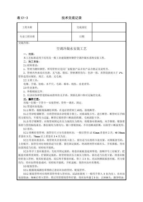
冷凝水管的安装
- 格式:doc
- 大小:34.50 KB
- 文档页数:2
空调冷凝水管安装规范空调冷凝水管安装规范空调冷凝水管是空调系统中一项重要的组成部分,它的安装质量直接影响到空调系统的正常运行和使用寿命。
以下是关于空调冷凝水管安装的一些规范,以确保安全和可靠的使用:1. 管道选材:冷凝水管道一般应采用高质量的PVC或者金属材料,具有良好的耐腐蚀性和耐高温性能。
2. 管道铺设:冷凝水管道应避免与电源线、信号线等其他线路横向交叉,且应保持一定的距离,避免互相干扰。
管道铺设应尽量避开易受损的区域和危险区域,如阳光直射、高温区域等。
3. 管道固定:冷凝水管道应有足够的支撑和固定,避免在使用过程中产生共振或者摇晃。
固定应使用专用的管夹或者固定架,均匀分布在管道各个连接点,并确保固定牢固。
4. 弯头和三通设置:在冷凝水管道中,存在弯头和三通等接头,应尽量减少接头数量并采用半径较大的弯头,以减小水流的阻力,避免堵塞和漏水现象。
5. 管道斜度:冷凝水管道应设置一定的斜度,以确保水能够顺利排出。
一般来说,每米管道的坡度不应小于3毫米。
6. 底板防漏:冷凝水管道的底板应采用防漏措施,以防止水渗漏到楼下。
可以在底板下铺设防水层,或者安装防漏板等措施。
7. 排水口设置:冷凝水管道应设置合适的排水口,以便将冷凝水及时排除。
排水口应设置在易于清理和维护的位置,并保持畅通。
8. 周期性检查:冷凝水管道在安装完成后,应定期检查一次,以确保其正常运行。
可检查冷凝水管道是否有渗漏和堵塞的情况,及时处理。
9. 安全阀设置:对于某些特殊情况下水流量较大的空调系统,应设置安全阀,以防止管道过载而破裂。
10. 操作规范:冷凝水管道在日常使用中,应注意避免过多沉积物或者杂质进入管道,以防止堵塞和水泄漏。
总之,空调冷凝水管的安装规范是确保空调系统正常运行和使用寿命的重要保障。
以上规范仅供参考,具体安装过程中还需根据实际情况进行具体规划和施工。
在安装过程中,要严格按照相关标准和要求操作,确保安全和可靠。
空调系统中的冷凝水管设计与安装全套-冷凝水管的选配和安装原则1、选配标准首先,我们需要考虑选择合适的管材。
通常情况下,常见的冷凝水管材质包括PVC和铜管。
PVC管具有轻便、抗腐蚀、低成本等优点,适用于大多数场景。
而铜管则更坚固耐用,适用于高负荷和高温度的系统。
因此,在选择管材时,需要根据具体的空调系统要求和建筑环境来做出决策。
其次,管径的选择也至关重要。
过小的管径会导致冷凝水排放不畅,容易堵塞,而过大的管径则会浪费材料和空间。
选择管径应该根据空调系统的容量和冷凝水的流量来确定,确保系统运行顺畅。
最后,管道的长度也需要根据建筑布局和地理环境来选择。
过长的管道可能会增加系统的阻力,而过短的管道则可能无法满足需要。
在选择长度时,需要充分考虑冷凝水的排放点和系统的布局。
2.安装原则为了保证冷凝水管的顺畅排水,以下是一些安装原则:(1)管道的坡度:冷凝水管应该具有适当的坡度,以确保水能够顺利流向排水点。
通常,每米长度的坡度应在5毫米到10毫米之间。
(2)弯头数量的最优化:过多的弯头会增加水流的阻力,降低排水效率。
因此,在设计中应尽量减少弯头的数量,或者使用弯头半径较大的型号。
(3)管道支架的稳固性:管道支架应安装稳固,以防止管道下垂或摇晃。
这有助于保持管道的坡度和排水效率。
(4)系统兼容性:不同类型的空调系统对冷凝水管材质和尺寸有特定的要求。
在安装新管道或更换现有管道时,必须确保其与系统兼容。
这包括管材的选配、管径的匹配以及连接方式的符合。
二冷凝水管设计安装的步骤(1)初步设计:从建筑结构和空调系统的布局出发,规划管道的初步走向。
考虑建筑的结构特点和使用功能,优化管道布局。
(2)详细规划:深入细化管道的具体布局,包括连接点、转弯处和坡度。
讨论如何在设计中融入检修和清洁的便利性。
(3)安装准备:列出安装所需的工具和材料清单,包括管道、接头、固定件和密封材料等。
准备阶段还包括施工人员的培训和安全教育。
(4)实际安装:实际安装阶段涵盖了从管道铺设到连接、固定以及密封的具体步骤。
冷凝水管安装工艺流程下载温馨提示:该文档是我店铺精心编制而成,希望大家下载以后,能够帮助大家解决实际的问题。
文档下载后可定制随意修改,请根据实际需要进行相应的调整和使用,谢谢!并且,本店铺为大家提供各种各样类型的实用资料,如教育随笔、日记赏析、句子摘抄、古诗大全、经典美文、话题作文、工作总结、词语解析、文案摘录、其他资料等等,如想了解不同资料格式和写法,敬请关注!Download tips: This document is carefully compiled by theeditor. I hope that after you download them,they can help yousolve practical problems. The document can be customized andmodified after downloading,please adjust and use it according toactual needs, thank you!In addition, our shop provides you with various types ofpractical materials,such as educational essays, diaryappreciation,sentence excerpts,ancient poems,classic articles,topic composition,work summary,word parsing,copy excerpts,other materials and so on,want to know different data formats andwriting methods,please pay attention!冷凝水管安装工艺流程一、准备工作阶段在进行冷凝水管安装之前,需要进行以下准备工作:1. 确定安装位置:根据空调系统的设计要求,确定冷凝水管的安装位置。
多联机冷凝水管安装操作方法随着现代化建筑的不断进步,人们的舒适要求也越来越高,多联机空调作为目前市面上最流行的空调类型之一,其节能、环保的功效已经深受大众的认可。
但是在多联机空调的安装过程中,冷凝水管的连接和安装是至关重要的一步。
正确的安装方式和步骤不仅能保证冷凝水的顺畅排出,还能延长空调的使用寿命,本文将介绍多联机冷凝水管的安装操作方法,希望能对广大空调安装维修人员提供一定的指导。
一、工具材料准备在安装多联机冷凝水管之前,首先需要准备必要的工具和材料。
常规情况下,需要准备冷凝水排水管、T接管、螺丝刀、扳手、万能钳、基础工具箱等。
二、准备工作在安装冷凝水管之前,需要进行必要的准备工作。
第一步是查看空调箱体的背面,确认多联机冷凝水排水口的位置,为后面的安装作好铺垫。
第二步是对接冷凝水排水管,需要将上方的侧板打开,然后将排水管伸入至约1-2厘米即可。
第三步是准备T接管,将其固定在多联机上方,保证其与排水口处于同一高度。
最后一步是在T接管和排水管之间进行连接,紧固好螺丝和扣环等配件,确保连接紧密牢固。
三、冷凝水管安装安装多联机冷凝水管的具体步骤如下:1. 将T形接头固定在空调主体上方,保证T形接头与空调主体底部平行,且两者之间距离约为10-15厘米。
2. 用钳子将T形接头固定在空调主体上方的螺丝上。
3. 在T形接头与空调主体之间连接冷凝水排水管,确保其连接紧密牢固。
在这个过程中需要特别注意排水管的长度和安装位置,不能太靠近地面,否则容易造成地面积水的情况,影响家居环境。
4. 最后在排水管的下方安装一个水尽头,保证冷凝水可以流畅的排出。
水尽头的安装位置需要在排水口的下方,距地面大概5-10厘米的位置,这样能够保证冷凝水有效排出,并达到预期的效果。
四、安装注意事项在安装多联机冷凝水管的过程中,需要注意以下事项:1. 确保连接部位牢固:在接头处使用T型管和螺丝之类的配件连接时,须将螺丝拧紧,以确保连接部位牢固可靠,不易损坏。

Condensing Boiler Industry guidance for installers - endorsed by HHIC membersBritish Standards, Building Regulations and industry guidance currently advise on how condensate discharge pipes should, be run either internally or externally, or a combination of both. This document gives guidance on how to install the pipes in order to reduce the possibility of freezing.However, in certain circumstances this guidance may not be sufficient to prevent freezing in extreme conditions with widespread and prolonged sub-zero temperatures.With the UK weather patterns showing more “extremes” in future due to the effects of global climate change, the following guidance updates previousrecommendations on condensate discharge pipe installation. In addition to this guidance all other technical requirements for condensate discharge installation given in British Standard BS 6798:2014, or in boiler manufacturers’ installation instructions should still be followed.****Boiler Manufacturer’s Warranty InformationIt should be noted that where the manufacturer’s instructions have not been followed then the boiler warranty may not be valid.In April 2005 revisions to the Building Regulations came into force, stat-ing that all replacement gas or oil boilers must be a condensing type. The introduction of condensing boilers has been fundamental in reducing the UK’s carbon emissions.In 2010 and again in 2018 the UK experienced prolonged spells of sub-zero temperatures down to minus 20 centigrade and below in many areas. This resulted in a significant increase in the number of calls to boilermanufacturers and heating engineers from householders with condensing (high efficiency) boilers where the condensate discharge pipe had frozen and become blocked with ice causing the boiler to shut down. In the vast majority of cases such problems occur where the condensate discharge pipe is located externally to the building for some part or all of its length.Note - the Benchmark Commissioning checklistsupplied with the boiler and detailed in the manufacturer’s instructions requires the heating engineer to confirm that the condensate drain has been fitted correctly.Summary of main requirementsInternal Condensate Pipe Discharge ConnectionWhere an installer is fitting a new or replacement boiler, the condensate discharge pipe should be connected to an internal “gravity discharge point” such as an internal soil stack (preferred method), internal kitchen or bathroom waste pipe such as sink, basin, bath or shower waste. External pipes from sink wastes or washing machine outlets should be a minimum of 30mm internal diameter, insulated with waterproof UV resistant material, terminated below the grid but above the water line and a suitable drain/leaf guard fitted. The end of the waste pipe should be cut at 45 degrees where it terminates into the grid to help reduce the potential for the pipe to freeze. Condensate PumpsWhere it is not possible to connect the boiler condensate discharge pipe to an internal “gravity discharge point” then the installer should use a condensate pump connected to a suitable internal connection point such as an internal soil stack (preferred method), internal kitchen or bathroom waste pipe such as a sink, basin, bath or shower waste.Existing InstallationsWhen servicing or repairing a boiler the heating engineer should check any boiler installations especially those that have external condensate drains to see if they can be terminated internally or upgraded to the latest guidance. The responsible person (home owner) should be advised and it is recommended that the installer completes the responsible persons frozen condensate information leaflet as a suitable means for advising the work that is required. See annex AThis guidance should be followed where work is carried out to “upgrade” the condensate discharge system to reduce the risk of freezing in extreme conditions and it is recommended that the condensate pipe is identified with a suitable label or marking even if the responsible person does not go ahead with the upgrade so as to allow easier identification in the future.Manufacturer’s instructions must be followed for the correct connection of the condensate discharge pipe from the boiler as this may vary due to the design of the boiler. For example a visible air break and trap is not required if there is a trap with a minimum condensate seal of 75 mm incorporated into the boiler. Internal Pipe Run In Unheated SpacesCondensate discharge pipes that are routed in an unheated space such as a loft or garage should be insulated to prevent freezing.Internal Condensate Pipe Discharge TerminationInternal condensate discharge pipework must be a minimum of 19mm ID (typically 22mm OD) plastic pipe or as per manufacturer’s instructions and this should “fall” a minimum of 45mm per metre away from the boiler, taking the shortest practicable route to the termination point.(45mm as per BS6798, 52mm per metre as per industry practice is specified in the following diagrams)To minimise the risk of freezing during prolonged sub-zero conditions, an internal “gravity discharge point” such as an internal soil stack (preferred method), internal kitchen, utility room or bathroom waste pipe e.g. from a sink, basin, bath or shower should be adopted, where possible.Note - A suitable permanent connection to the foul waste pipe should be used.Figures 1, 2(a), 2(b) show appropriate connection methods.182573Figure 2(a) – Connection of a condensate discharge pipe downstream of a sink, basin, bath or shower waste trap.Note – Check manufacturer’s instructions to see if an air break is required.Key 1 Boiler2 Visible air break3 75 mm trap4 Visible air break and trap not required if there is a trap with a minimum condensate seal of 75 mm incorporated into the boiler. In this case the 100 mm is measured to the trap in the boiler.5 Sink, basin, bath or shower6 Open end of condensate discharge pipe direct into gully 25 mm min below grating but above water level; end cut at 45 °Note – the maximum external condensate discharge length is 3 metres7 Sink lip8 Minimum internal diameter 19 mm 9 Pipe size transition10 Minimum internal diameter 30 mm 11 Water/weather proof insulation 12 Drain cover/leaf guard121059483761112Visible air break at plug hole – alternative connection can be below sink trap 75 mm sink, basin, bath or shower waste trap Sink, basin, bath or shower with integral overflowOpen end of condensate discharge pipe direct into gully 25 mm min below grating but above water level; end cut at 45 °12105948376The possibility of waste pipes freezing downstream of the connection point should be considered when determining a suitable connection point - e.g. a slightly longer pipe run to an internal soil stack may be preferable to a shorter run connecting into a kitchen waste pipe discharging directly through the wall to an external drain.Note - Where “gravity discharge” to an internal termination is not physically possible (e.g. the discharge point is above the appliance location, or access is obstructed by a doorway), or where very long internal pipe runs would be required to reach a suitable discharge point, then a condensate pump should be used.External waste pipes from kitchens, utility rooms or bathrooms such as sink, basin, and bath or shower waste outlets should be insulated with waterproof UV resistant, class 0 material, terminated below the grid but above the water line and a drain/leaf guard fitted. The waste pipe should be cut at 45 degrees where it terminates into the grid. (See insulation section for guidance on suitable materials).Condensate PumpsUse of a Condensate Pump to an Internal TerminationCondensate can be removed using a proprietary condensate pump, of a specification recommended by the boiler or pump manufacturer. In order to minimise the risk of freezing during prolonged sub-zero spells, one of the following methods internal to the property for terminating the boiler condensate pump to a foul water discharge point should be adopted such as an internal soil stack (preferred method), internal kitchen, utility room or bathroom waste pipe such as sink, basin, and bath or shower waste. Figure 3 shows a typical connection method.Manufacturers Instructions must be referred to when installing boiler condensate discharge pipes Manufacturers Instructions must be referred to when installing boiler condensate discharge pipes 2543112345106789External ConnectionsOnly fit an external boiler condensate drain connection if an internal gravity or pumped connection is impractical to install.The pipe work from the boiler should be of a minimum 19mm ID or as per manufacturer’s instructions and the condensate discharge pipe shall be run in a standard drainpipe material, e.g. poly (vinyl chloride) (PVC), un-plasticized poly (vinyl chloride) (PVC-U), acrylonitrile butadiene-styrene (ABS), polypropylene (PP) or chlorinated poly (vinyl chloride) (PVC-C).Note - Fixing centres for brackets should be a maximum of 300mm for flexible pipe and 500mm for solid pipe and manufacturer’s recommendations should be followed.The condensate pipe should be run internally as far as possible before going externally and the pipe diameter should be increased to a minimum of 30mm ID (typically 32mm OD) before it passes through the wall. The angle of the pipe should slope downwards by at least 3 degrees as it passes through the wall to assist in maintaining a good velocity as the condensate exits the building.The external pipe run should be kept as short as possible to a maximum of 3 metres, taking the most direct and “most vertical” route to the discharge point, with no horizontal sections in which condensate might collect.Manufacturers Instructions must be referred to when installing boiler condensate discharge pipes Manufacturers Instructions must be referred to when installing boiler condensate discharge pipes Visible air break Visible air break and trap not required if there is a trap with a minimum condensate seal of 75mm incorporated into the boiler.Soil and vent stack 450mm minimum upto three storeysMinimum internal diameter 19 mm Pipe size transition pointMinimum internal diameter 30mm Water/weather proof insulation1210594837611Alternative SolutionsCold weather protection methods approved or endorsed by boiler manufacturers and/or service organisations may be adopted if these are considered suitable by the parties involved. It is the responsibility of the manufacturer of these products to ensure they have completed the necessary testing or calculations to ensure the product offers suitable protection to prevent the condensate pipe from freezing. The product manufacturer should provide information as to what level of external temperature and for what time period the product can protect against sub-zero temperatures, i.e. -15°C for 48 hours. BS6798 refers to devices that pump the condensate produced by a condensing boiler to a fine misting nozzle in the boiler flue terminal so that the condensate is discharged with the hot flue gas. (BS6798 section 6.3.8 note 4). The boiler manufacturer’s instructions will provide advice regarding fitting and siting of the flue terminal to ensure safe disposal of the condensate.Additional MeasuresAt least one of the following measures should be fitted in addition to the measures detailed above for external condensate discharge pipes• Insulate external pipe with a minimum thickness of insulation to be 19mm “O” class PVC coated material.• Fit trace heating – with insulation as recommended by manufacturer.• Fit internal auxiliary(additional) high volume syphon unitAuxiliary Syphon – Fitted InternallyAuxiliary siphons fitted inside the premises assist with the siting of the boiler where an external condensate pipe must be fitted. The storage capacity of the auxiliary siphon increases the volume of condensate discharge reducing the risk of freezing. A further reduction in the potential for the pipe to freeze is achieved when combined with the external insulation requirements.Electric Trace HeatingTrace heating with an external thermostat can be fitted to the external condensate pipe to raise the temperature of the condensate pipe in freezing conditions. Trace heating takes the form of an electrical heating element run in physical contact along the length of the condensate pipe. The pipe is usually covered with thermal insulation to retain heat losses from the pipe. Heat generated by the element then maintains the temperature of the pipe. If such a system is used then the installation instructions of the trace heating manufacturer and any specific recommendations regarding pipe diameter, insulation, etc. should be followed. All other relevant guidance on condensate discharge pipe installation should also be followed.Insulation MaterialsInsulation used for external condensate pipes, sink or washing machine waste pipes should be of class ‘O’ grade with an outer coating that is weather proof, bird/animal proof, and UV resistant finish. A minimum of 19mm thick insulation is recommended for 32mm external pipes.Use of Air Breaks In Condensate Discharge PipesHeating engineers should follow manufacturer’s instructions on the use of air breaks in condensate discharge pipes. A visible air break is not required if the boiler condensate trap has a minimum condensate seal of 75mm incorporated into the boiler.Connecting to a rain water downpipe/External Soil StackWhen an external soil stack or rain water downpipe is used as the termination (NB only permissible if this downpipe passes to a combined foul and rainwater drainage system) an external air break must be installed between the condensate discharge pipe and the downpipe to avoid reverse flow of rainwater/sewage into the boiler should the downpipe itself become flooded or frozen.Figure 5 shows a suitable connection method. Pipe insulation should be fitted.Figure 5 – External termination to rainwater downpipe (NB only combined foul/rainwater drain)Key1 Condensate discharge pipe from boiler2 Pipe size transition point3 Water/weather proof insulation4 43mm 90° male/female bend5 External rain water pipe into foul water6 External air break7 Air gap8 68mm PVCu strap on fitting 9 Minimum internal diameter 19mm 10 Minimum internal diameter 30mm 11 End cut at 45°1210594837611External Termination of the Condensate PipeWhere the condensate discharge pipe is terminated over an open foul drain or gully, the pipe should terminate below the grating level, but above water level, in order to minimise “wind chill” at the open end. Pipe drainage and resistance to freezing will be improved if the termination end of the condensate pipe is cut at 45 degrees as opposed to a straight cut.The use of a drain cover (such as those used to prevent blockage by leaves) must be fitted to offer further protection from wind chill. Figure 6 (following page)shows a suitable connection method. Where the condensate drain pipe terminates in a purpose-designed soakaway (see BS 6798:2014 or boiler installation manual for soakaway design requirements) any above-ground section of condensate discharge pipe should be run and insulated as described above. Figure 7 (following page) shows a suitable connection method.Unheated Areas in BuildingsInternal condensate drainage pipes run in unheated areas such as lofts, basements and garages should be treated as external connections and insulated accordingly. Weather proof materials may not be necessary and should be assessed by the heating engineer.Use of Air Breaks In Condensate Discharge PipesInstallers should follow the manufacturer’s instructions on the use of air breaks in condensate discharge pipes. A visible air break and trap is not required if the boiler condensate trap has a minimum condensate seal of 75 mm incorporated into the boiler.Figure 6 – External drain, gully or rainwater hopperKey 1 Boiler2 Visible air break3 38mm minimum trap4 Visible air break and trap not required if there is a trap with a minimum condensate seal of 38 mm incorporated into the boiler – refer to manufacturers instructions5 External length of pipe 3 m maximum6 Open end of condensate discharge pipe direct into gully 25 mm min below grating but above water level; end cut at 45 °7 Minimum internal diameter 19 mm8 Pipe size transition point 9 Minimum internal diameter 30 mm 10 Water/weather proof insulation 11 Fit drain cover/leaf guard12105948376Manufacturers Instructions must be referred to when installing boiler condensate discharge pipes Manufacturers Instructions must be referred to when installing boiler condensate discharge pipesManufacturers Instructions must be referred to w installing boiler condensate discharge pipes Figure 7 – Example of a purpose made soakawayKey1 Condensate discharge pipe from boiler2 Ground (this section of the condensate discharge pipe may be run either above or below round level); End cut at 45°3 Diameter 100 mm minimum plastic tube4 Bottom of tube sealed5 Limestone chippings6 Two rows of three 12 mm holes at 25 mm centres, 50 mm from bottom of tube and facing away from house7 Hole depth 400 mm minimum by 300 mm diameter 8 Minimum internal diameter 19 mm 9 Pipe size transition point10 Minimum internal diameter 30 mm 11 Water/weather proof insulation11059483761101926 513777*************.ukCamden House Warwick Road Kenilworth CV8 1THOur customer information guide on frozen boiler condensatedischarge is also available for download.It includes a condensate assessment form, for engineers to complete and advice to customers during extreme cold weatherCondensing BoilerGuidance and advice for customers- endorsed by the Heating and Hotwater Industry Council, HHIC。
空调水管的制作、安装1、管材使用及连接要求1)空调水管(冷冻、热水管)直径DN20-DN100采用热镀锌钢管,直径DN100以上采用无缝钢管。
2)空调冷凝水管(包括新风机组、风机盘管、分体空调器)采用PVC管。
3)风机盘管接口至关断阀之间的管道采用铜制软管,其工作压力为1.0MPa。
2、管道安装一般要求1)空调供回水立管及水平管翻高形成气囊的最高处设置排气装置,立管及水平管翻低的最低处设置排水装置,立管底部排水阀应有不小于100mm的集污管段长度。
2)空调冷凝水管应顺排水方向设置坡度安装,严禁倒坡。
空调机组(包括新风机组)冷凝水管出口处应设存水弯或其他隔气措施。
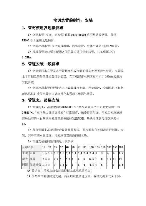
3、管道支、吊架安装1)管道的支、吊架按国标03SR417-2“装配式管道吊挂支架安装图”和95R417-1“室内热力管道支吊架”标准制作。
保冷管道与支、吊架之间应垫经防腐处理的木衬垫或高密度难燃型酚醛发泡鞍座,垫块厚度就与绝热厚度相同。
2)所有管道支吊架须符合设计规范要求,并按国家有关标准进行制作、安装,其中空调水管道支、吊架应设置隔热的硬木垫。
3)管道支吊架间距须满足下表要求:1)在某些重要设固定支架,其余均设置普通支架,各种支架形式见下图:注意事项:因楼面为预应力钢筋混凝土结构,为避免损坏钢筋,支吊架固定前要与土建施工单位配合好。
施工顺序为:能沿墙、柱敷设的尽可能沿墙面、柱面敷设。
单管支架形式普通排管吊架棚固定形式: 排管吊架梁固定形式:4、管道安装质量要求1)管道安装前必须将管内的污物清除干净,施工过程中主管上的三通孔用胶带封闭,待与支管连接时去掉封闭胶带,进行连接;2)管道切割:小管径管材采用机械切割;大管径管材采用氧气-乙炔切割,砂轮机打磨;3)管道穿墙或楼板处必须设置套管,套管直径应比管道直径大2号。
安装在墙体内的套管,其两端应与墙饰面相平;穿楼板的套管应高出建筑面层20mm (厨房、卫生间内应高出地面50mm )。
4)管道的焊缝不得设在套管内,保温工程竣工后,套管与保温层外径之间的空隙用不燃保温材料塞紧。

随着家用中央空调的普及,为了中央空调能够正常的使用,不管是安装人员还是用户都要掌握一点隐蔽工程安装知识,至少知道点隐蔽工程的安装细节。
第一、材料的选购,现在大部分工程公司都是采用给水U-PVC管,专用胶黏结。
其他可选用材质有:PP-R管、PP-C管和热镀锌钢管;不允许使用铝塑复合管。
第二、排水管安装准备:冷凝水管安装前,应确定其走向和标高,避免与其他管线交叉,以保证坡度顺直;管道吊架的固定卡子高度应当可以调节,并在保温外部固定。
通常可根据冷负荷的大小选择确定冷凝水管的公称直径。
第三、是管路的坡度,为了使冷凝水顺利排出室外,内机到主管道必须有1%的坡度,干管坡度不得少于0.3%,且不得出现倒坡。
这个坡度不能太大,坡度太大,后面的冷凝水管太低,影响用户的吊顶标高,如果影响了吊顶的高度,有可能就会被装修的抬高,虽然管路.上有提示标识,也不能保证装修的工人不抬高冷凝水管。
注:排水管干管的管径不宜小于32mm。
第四、防止对冲,水平排水管必须避免对冲现象,以免出现倒坡和排水不畅。
解决对冲的方法请参照下图:第五:设置通气孔,排水管最高点应设通气孔,以保证冷凝水顺利排出,排气口必须朝下,以免污物进入管道内。
第六、排水管吊架间距:具体操作方法是:首先把冷凝水管总出水口堵上,然后用水把每一个接水盘都充满水,检查水管的每一个接头是否有漏水或者渗水,如果没有渗水,四个小时以后就可以给冷凝水管保温。
第七、通水和满水试验:管道连接完成后,应做通水试验和满水试验,一方面检查排水是否畅通,另一方面检查管道系统是否漏水。
提醒:冷凝水管做完12小时已后,-定要做通水试验和满水试验,通水试验就是给每一个内机接水盘内倒入干净的水,查看冷凝水管是否能顺利排出,满水试验很多人不知道做,这个稍微有点复杂,第八、水管保温:保温材料接缝处,必须用专用胶粘接,然后缠橡塑.胶带,橡塑胶带宽度不小50mm,保证牢固,防止凝露。
因为冷凝水水温较低,流入冷凝水管之后会因为温度差在冷凝水管外壁产生凝露。
雨水管及空调冷凝水管管道安装技术交底一、施工准备(一)材料要求1、管材为硬质聚氯乙烯(UPVC)2、管材内外表层应光滑,无气泡、裂纹,管壁薄厚均匀,色泽一致。
直管段挠度不大于1%。
管件造型应规矩、光滑、无毛剌。
承口应有梢度,并与插口配套。
3、其它材料:粘结剂、圆钢、卡件、螺栓、螺母、肥皂等。
(二)主要机具吊篮、电锤、手锯、胶枪、水平尺、毛刷、棉布、线坠等。
(三)作业条件1、外墙吊篮已安装完成,并验收合格。
2、应核对各种管道的标高、排列有无矛盾。
预留孔洞已配合完成。
场地清理干净。
二、质量要求(一)主控项目1、管道的材质、规格、尺寸、粘接剂的技术性能必须符合设计要求。
2、排水塑料管必须按设计要求装伸缩节。
如设计无要求,伸缩节间距不大于4m。
检验方法:观察和尺量检查。
3、排水系统竣工后的通水试验结果,必须符合设计要求和施工规范规定。
检验方法:通水检查或检查通水试验记录。
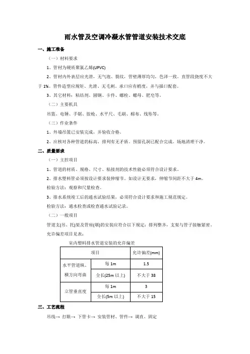
(二)一般项目管道支(吊、托)架及管座(墩)的安装应符合以下规定:排列整齐,支架与管子接触紧密。
允许偏差项目见表:室内塑料排水管道安装的允许偏差三、工艺流程吊线→打眼→下管卡→安装管材、管件→调直、固定四、施工工艺1、预制加工:根据图纸要求并结合实际情况,按预留口位置测量尺寸,进行断管。
断口要平齐。
粘结前用棉布将承插口需粘结部位的水分、灰尘擦拭干净。
用毛刷涂抹粘结剂,先涂抹承口后涂抹插口,随即用力垂直插入,插入粘结时将插口稍作转动,以利粘结剂分布均匀,约30秒至一分钟即可粘结牢固。
粘牢后立即将溢出的粘结剂擦拭干净。
多口粘连时应注意预留口方向。
2、安装:根据图纸要求从上至下吊通线,雨水管用Φ110硬质聚氯乙烯(UPVC),要求管外壁距墙2.5—3mm,用电锤在外墙上打眼,然后将洞内粉尘吹净,将管卡打入洞内固定牢固,雨水管与雨水斗粘接后紧贴铁制雨水口下沿,雨水管安装不加伸缩节。
3、空调板处立管每层居中打一个管卡,每层混凝土板处做吊洞处理。
4、空调冷凝水管用Φ50硬质聚氯乙烯(UPVC)管,在冷凝水立管上距空调板200mm使用Φ50斜三通做为空调冷凝水接口。
空调冷凝水排水管做法对于我们要家里所安装的空调,都有专用的排水的管道。
像现在新建的楼房,在每一个空调机位的位置,都有一根专用的空调的冷凝水的排水管道。
如果没有冷凝水的排水管道,这些水可能就四处飞溅。
而我们在安装的时候,一般要把空调本身的冷凝水管道接入到空调专用的冷凝水排水管,这样来保证正常的排水。
但是如果接不进去怎么办呢?家居杂坛在这篇文章中开大家解答空调冷凝水排放的问题。
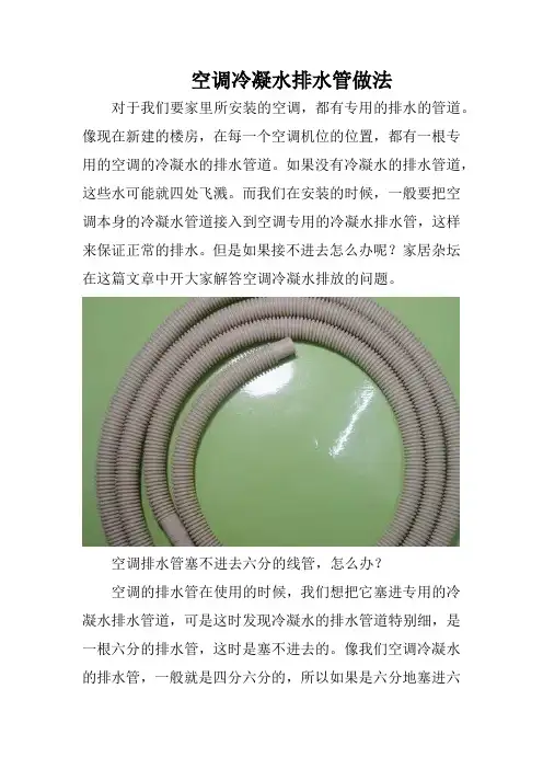
空调排水管塞不进去六分的线管,怎么办?空调的排水管在使用的时候,我们想把它塞进专用的冷凝水排水管道,可是这时发现冷凝水的排水管道特别细,是一根六分的排水管,这时是塞不进去的。
像我们空调冷凝水的排水管,一般就是四分六分的,所以如果是六分地塞进六分的管道里肯定是很难的。
那么这个时候怎么办呢?家居杂坛给大家推荐以下的处理建议。
①:将六分的排水的线管进行变径处理。
也就说我们此时是有排水的管道的,但是管道的管径太小,是六分管,也就是我们所常说的20管,那么这个时候个人建议大家买一个20变32的变径,然后安装到我们的六分的管道上。
最后再安装一根32的短管。
这样我们就重新接出来一个冷凝水的排水管。
最后我们将我们的冷凝水排水管插入这根32的管道中就可以了。
②:安装专用的排水三通。
如果我们发现所安装的冷凝水管过细,不能够使用,那么这时候我们同样也可以采取安装一个专用的排水三通。
排水三通一般也是32mm的。
我们在安装的时候要找到原来的排水管道,也就是冷凝水排水管,之后将冷凝水排水管切开。
然后把专用的冷凝水排水三通安装上去。
这样就可以保证我们空调的冷水的正常排放。
③:将空调自带的冷凝水排管延长,然后找到合适的地方进行排放。
这里所说的就是我们原来的冷凝水的排水管道过细。
没有没有办法进行安装,而且我们自己也不会改装原来的冷凝水排出管道。
那么这时就将我们家里空调冷凝水的排水管加长。
因为像空调冷凝水的排水管,我们都可以买到同规格的,然后把它安装在一起,就可以加长。
空调(风管机)安装方案步骤:确定需要打洞的位置-→使用电钻打洞-→安装穿线管-→处理墙面,使用填缝剂填补洞口并进行打磨,使其与周围墙面平齐。
3、冷媒配管步骤:在室内机和室外机之间连接冷媒配管-→使用弯头和接头来确保管道的弯曲和连接-→使用电缆扎带固定管道,以确保其稳定。
4、冷凝水管的安装步骤:连接冷凝水管-→将管道安装在适当的位置-→使用电缆扎带固定管道,以确保其稳定-→在管道的末端安装排水管,以确保冷凝水能够顺畅排出。
5、通风管道施工工艺步骤:根据设计图纸确定通风管道的位置-→使用钢板或其他材料制作管道-→使用连接器连接管道-→使用电缆扎带固定管道,以确保其稳定。
6、控制线作业步骤:安装控制线-→将控制线连接到室内机和室外机-→使用电缆扎带固定控制线,以确保其稳定。
7、绝热工作步骤:在冷媒配管和通风管道上进行绝热处理-→使用绝缘材料包裹管道-→使用胶带固定绝缘材料,以确保其牢固。
8、室外机的安装步骤:决定室外机的位置-→画线标志-→打膨胀螺栓-→安装室外机,使用垫片来确保室外机的平稳。
9、气密性试验步骤:使用专业工具对管道进行气密性测试-→检查是否存在漏气情况-→及时修复漏气问题。
10、真空干燥步骤:使用专业工具对管道进行真空干燥-→排除管道中的空气和水分-→确保管道内干燥,以保证冷媒系统的正常运行。
11、制冷剂的加注步骤:向冷媒系统中加注制冷剂-→确保加注量符合设计要求-→使用专业工具进行加注,以确保安全。
12、试机调试步骤:对整个系统进行试机调试-→检查系统是否正常运行-→及时修复出现的问题。
13、竣工验收与交工验收步骤:进行竣工验收和交工验收-→确保系统符合设计要求-→保证系统的安全可靠。
在进行打洞作业前,需要核准洞孔的位置和尺寸,并在墙板上标出洞孔的大小。
需要征得现场土建技术人员的意见,以确保打孔不会影响建筑物的结构。
采用电锤打孔,但如果墙壁不适合使用电锤打孔,需要征得业主的同意并采用其他方式打孔。
空调冷凝水管安装需要注意的问题在炎热的夏天,空调就像是我们最好的朋友,吹着凉风,带来无尽的舒适。
不过,你知道吗?这位好朋友要想长久地陪伴我们,冷凝水管的安装可得小心翼翼,真是马虎不得。
来,咱们聊聊冷凝水管安装的一些小窍门,让你轻松驾驭这门“技术”。
选对位置可真是重中之重。
冷凝水管要排水,得保证水流畅通无阻。
你想啊,要是管道弯弯曲曲,水可就像是老鼠进了迷宫,根本找不到出口。
一定要找个直通的地方,这样水流才能像喷泉一样,呼啸而出,绝不留情。
安装位置得离地面有点距离,避免那些不速之客,比如小虫子,能趁机爬进管子里开派对。
说到管道的材质,选择也不能马虎。
市场上有很多种冷凝水管,但塑料管是个不错的选择,轻巧耐用,安装也简单。
更重要的是,塑料管不容易被腐蚀,这一点尤为关键。
要是用铜管,虽然看起来很高档,但一旦时间久了,可能就会出现漏水的尴尬场面,那可真是让人哭笑不得。
管道的坡度也得注意,坡度太小可就像小溪流不动,容易造成积水,发霉的风险可就高了。
坡度太大,又怕水流得太快,直接飞出管子,那也是个麻烦事。
一般来说,3%到5%的坡度比较合适,既能让水顺畅流动,又不至于飞出去。
安装时,管道的连接要牢固,避免渗漏。
有的人可能觉得,哎呀,反正只是冷凝水,漏一点无所谓。
可你想想,长此以往,水滴石穿,那就不好了。
再说了,漏水的地方,墙壁可能会发霉,变成一个“小花园”,那可是看着让人心烦的呀!咱们聊聊那些配件。
用好配件,能让冷凝水管更“顺畅”。
比如,弯头和接头的选择,得考虑到水流的方向和流速。
如果用得不对,水可就会在某个地方打转,简直成了个“水漩涡”。
所以,买配件的时候,别小看了这些小东西,挑选靠谱的品牌,安心又放心。
绝对不要忽视排水口的清理。
定期检查,别让脏东西占了上风。
就像我们的生活,总得清理一下,保持干净整洁,不然久而久之,问题可就大了。
排水口如果堵了,冷凝水就会反扑到空调内部,那就真是自掘坟墓了。
管道的固定也得做得牢靠。
冷凝水管道安装技术要求
冷凝水支管应采用斜三通或落水弯头与竖管连接,两支管合流时错位方法连接。
固定件间距不大于3m。
楼层高度小于或等于4m,立管可安装1个固定件。
立管安装前清理场地,根据需要支搭操作平台。
清理已预留的伸缩节,将锁母拧下,取出U型橡胶圈,清理杂物。
复查上层洞口是否合适。
立管插入端应先划好插入长度标记,然后涂上肥皂液,套上锁母及U型橡胶圈。
安装时先将立管上端伸入上一层洞口内,垂直用力插入至标记为止。
合适后即用自制U型钢制抱卡紧固于伸缩节上。
冷凝水排水管安装规范
一、冷凝水管排放的施工要求:
1冷凝水管安装前须将其内壁清理干净。
2冷凝水管对接或拐弯时须用直通和弯头粘接。
3冷凝水管须以设计规定的坡度排放,以保证出水畅通。
4所有粘接须尽可能牢固,严防漏水。
5保温管与冷凝水管须接触紧密,外观漂亮。
6冷凝水管每1.5-2m左右须装吊钩。
7冷凝水管在安装完毕后需注水试漏。
二、冷凝水管的布置
1若邻近有下水管或地沟时,可用冷凝水管将空调器接水盘所接的凝结水排放至邻近的下水管中或地沟内。
2若相邻近的多台空调器距下水管或地沟较远,可用冷凝水干管将各台空调器的冷凝水支管和下水管或地沟连接起来。
技术交底
工程名称交底时间年月日
工程部位空调冷凝水管道安装交底对象
交底人接收人
参加交底人员
冷凝水管的安装:
1、内机安装高度必须有5公分水位,保证水流通畅。
2、确认冷凝水管的走向及落水口位置,有必要还要设存水弯,防止异味进入内机。
3、管道走向美观,排水管的接头必须用胶水接牢靠,
4、安装坡度至少1/100。
水管不准走回风口中间,尽量走机器后方。
5、落水口就近设置,不应放在卫生间地漏,应放在阳台或在室外。
6、用吊架或卡扣固定,间距0.8M~1.0M之间。
严禁用电线固定。
7、必须套保温管,防凝结水。
8、墙体里走管道,粉刷层必须在1公分以上。
9、隔墙(三合板、石膏板)里走排水管必须套保温管。
10、地面上走排水管,要开槽,必须用水泥加封处理。
外墙上的孔或卫生间开孔必须做好防漏措施(打泡沫胶等方法)。
11、机器原配软管不得弯曲,软管与内机连接处必须用胶水粘接或用原配卡环卡紧,保证连接牢靠。
12、内机设有提升水泵,得加提升管。
13、空调试水必须在两次以上,第一次试水在装潢封板前试水,有必要做满水试验,第二次在安装风口调试系统时必须试水。
14、排水管最高点应设通气孔,以保证冷凝水顺利排出,排气口必须朝下,以免污物进入管道内。
大连旺兴新能源科技有限公司。
空调冷凝水管安装规范空调冷凝水管安装规范一、总则空调冷凝水管是用于排放空调室内机产生的冷凝水的管道,其安装规范旨在确保冷凝水的有效排放,保证系统正常运行以及防止水管漏水等问题的发生。
二、材料选择1. 冷凝水管应选用具有良好耐腐蚀性能的材料,如PVC、聚丙烯、不锈钢等。
2. 冷凝水管的直径应根据室内机的冷凝水排放量来确定,通常在20mm至50mm之间。
三、安装位置1. 冷凝水管应尽量靠近室内机布置,避免过长的水管,减少压力损失。
2. 冷凝水管应选择合适的位置,远离电气设备和易受热源影响的地方,以防止冷凝水因受热蒸发而无法排放。
3. 冷凝水管的安装位置应避免长时间暴露在阳光下,以免影响管道的密封性能。
四、布置方式1. 冷凝水管在铺设过程中应保持坡度,确保冷凝水能够自然流动,避免积水现象的发生。
2. 冷凝水管在穿越墙体或屋顶时,应做好防水处理,确保冷凝水不会漏入房间内。
3. 冷凝水管在穿越横梁、楼板等地方时,应采用合适的固定支架进行固定,以防止管道松动或下垂。
五、连接方式1. 冷凝水管的连接应采用专用的接头或密封胶进行连接,确保连接处不会漏水。
2. 冷凝水管的连接处应使用密封胶进行防水处理,以防止水从连接处渗漏。
六、防冻措施1. 冷凝水管的绝缘层应具有良好的防冻性能,以防止水在寒冷环境中结冰堵塞管道。
2. 冷凝水管在穿越寒冷地区的室外空间时,应采取绝缘保护措施,如使用绝缘套管进行保护。
七、定期检查1. 冷凝水管安装完成后,应定期检查冷凝水排放是否畅通,以及连接处是否存在漏水问题。
2. 如发现冷凝水管有漏水或阻塞等问题,应及时修复或更换。
八、安全措施1. 冷凝水管安装过程中,应注意安全操作,避免人身伤害的发生。
2. 安装人员应经过专业培训,具备相关证书,严格按照相关安全规范进行操作。
以上是空调冷凝水管安装规范的主要内容,通过遵循这些规范可以确保冷凝水的有效排放,保证系统的正常运行,同时也能够避免水管漏水等问题对室内环境造成的损害。
3.1.7.冷凝水管的安装
在风机盘管机组、整体式空调器或者组合式空调机组等设备运行的过程中,都会产生冷凝水,这些冷凝水如不及时排走,会给工程造成严重后果。
由于本工程标准层高为3200mm,层高的限制使本工程的冷凝水管道应尽量分成小区域进行敷设,以最大可能的减少冷凝水水平管道的长度,使冷凝水及时排出。
冷凝水管道安装时要结合幕墙龙骨间隔、铝板与结构间隙等空间敷设,同时也要结合暖通、建筑节点、室内吊顶图,与外立面幕墙安装及室内装饰紧密配合,保证美观。
冷凝水管道在设计时如果发现与现场冲突,要及时与设计单位协商沟通,在保证外观的前提下做局部调整,。
3.1.7.1冷凝水管排放的施工要求及布置
(1)冷凝水管排放的施工要求:
1)冷凝水管安装前须将其内壁清理干净。
2)冷凝水管对接或拐弯时须用直通和弯头粘接。
3)冷凝水管须以设计规定的坡度排放,以保证出水畅通。
4)所有粘接须尽可能牢固,严防漏水。
5)保温管与冷凝水管须接触紧密,外观漂亮。
6)冷凝水管每1.5-2m左右须装吊钩。
7)冷凝水管在安装完毕后需注水试漏。
(2)冷凝水管的布置
1)若邻近有下水管或地沟时,可用冷凝水管将空调器接水盘所接的凝结水排放至邻近的下水管中或地沟内。
2)若相邻近的多台空调器距下水管或地沟较远,可用冷凝水干管将各台空调器的冷凝水支管和下水管或地沟连接起来。
3.1.7.2冷凝水管管径的确定
1)直接和空调器接水盘连接的冷凝水支管的管径应与接水盘接管管径一致(可从产品样本中查得)。
2)需设冷凝水干管时,某段干管的管径可依据与该管段连接的空调器总冷量 (KW)按下表查得。
说明:DN=15mm的管道不推荐使用。
立管的公称直径,应与同等负荷的水平干管的公称直径相同。
3.1.7.3冷凝水管保温
所有冷凝水管都应保温,以防冷凝水管温度低于局部空气露点温度时,其表面结露滴水。
采用带有网络线铝箔贴面的玻璃棉保温时,保温层厚度可取25mm。
3.1.7.4冷凝水管设计注意事项
1)沿水流方向,水平管道应保持不小于千分之一的坡度;且不允许有积水部位。
2)当冷凝水盘位于机组负压区段时,凝水盘的出水口处必须设置水封,水封的高度应比凝水盘处的负压(相当于水柱高度)大50%左右。
水封的出口,应与大气相通。
3)采用聚氯乙烯塑料管时,一般可以不必进行防结露的保温和隔汽处理。
4)采用镀锌钢管时,通常应设置保温层。
5)冷凝水立管的顶部,应设计通向大气的透气管。
6)设计和布置冷凝水管路时,必须认真考虑定期冲洗的可能性,并应设计安排必要的设施。
7)冷凝水管采用PVC管道时,应布置美观粘接牢固,试水试漏时,应打开设备的放气装置,让水充满整个PVC管道,持续24小时,以管道无渗漏,设备凝结水盘不承水为合格。