力信自动测量系统说明书5.0
- 格式:pdf
- 大小:1.73 MB
- 文档页数:86
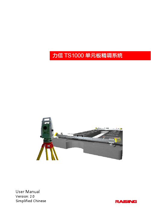
User ManualVersion: 2.0 Simplified Chinese 1力信TS1000单元板精调系统使用手册版 本:V2.0共 页(包括封面)拟 制 上海力信测量技术有限公司审 核会 签标准化批 准上海力信测量技术有限公司本手册由上海力信测量技术有限责任公司保留其修改权和解释权目录1引言 ............................................................................................................................................................... - 3 -1.1编写目的 ............................................................................................................................................ - 3 -1.2预期的读者和阅读建议 .................................................................................................................... - 3 -1.3 术语定义 ........................................................................................................................................... - 3 -1.4 参考资料 ........................................................................................................................................... - 3 -2 系统组成 ...................................................................................................................................................... - 4 -2.1 系统总体构成图 ............................................................................................................................... - 4 -3 硬件设备 ...................................................................................................................................................... - 5 -3.1徕卡全站仪 ........................................................................................................................................ - 5 -3.2徕卡手簿 ............................................................................................................................................ - 5 -3.3整体标架 ............................................................................................................................................ - 5 -4 软件概述 ...................................................................................................................................................... - 6 -4.1软件构成图 ........................................................................................................................................ - 6 - 5操作步骤 ....................................................................................................................................................... - 6 -5.1系统安装 ............................................................................................................................................ - 6 -5.1.1安装软件 ................................................................................................................................. - 6 -5.1.2架设全站仪 ............................................................................................................................. - 7 -5.1.3安放整体标架 ......................................................................................................................... - 7 -5.2系统初始化 ........................................................................................................................................ - 7 -5.2.1配置作业 ................................................................................................................................. - 7 -5.2.2输入设计线形 ......................................................................................................................... - 7 -5.2.3配置系统参数 ......................................................................................................................... - 7 -5.2.4配置徕卡手簿和全站仪 ......................................................................................................... - 7 -5.2.5全站仪自由设站 ..................................................................................................................... - 8 -5.2.6开启整体标架电源 ................................................................................................................. - 8 -5.2.7系统检校 ................................................................................................................................. - 8 -5.2.8人工照准棱镜 ......................................................................................................................... - 8 -5.3操作方法 ............................................................................................................................................ - 8 -5.3.1操作全站仪 ............................................................................................................................. - 8 -5.3.2操作整体标架 ......................................................................................................................... - 8 -5.3.3操作徕卡手簿 ......................................................................................................................... - 8 -‐ 1 ‐5.3.4操作软件 ................................................................................................................................. - 9 - 5.4系统卸载 .......................................................................................................................................... - 20 -5.4.1卸载整体标架 ....................................................................................................................... - 20 -5.4.2卸载全站仪 ........................................................................................................................... - 20 -5.4.3卸载三脚架 ........................................................................................................................... - 20 -5.4.4数据备份 ............................................................................................................................... - 20 -‐ 2 ‐1引言1.1编写目的本文通过详细描述力信TS1000单元板精调系统的系统组成、工作原理、操作方法、性能指标以及注意事项,目的是为了方便用户更快地了解、熟悉和掌握本系统的功能、操作方法。

RMS-D盾构自动导向系统技术手册1. 前言 (2)2. 系统概述 (2)3. 测量原理 (3)3.1RMS-D系统测量测量原理------------------------------------------------------------33.2人工测量原理---------------------------------------------------------------------------34. RMS-D自动导向系统与人工测量原理精度比较 (4)5.同其他测量系统的比较 (5)6. RMS-D导向系统的特点 (5)7. 系统组成 (6)8. RMS-D软件 (8)8.1三个模块所实现的功能---------------------------------------------------------------88.1.1 数据准备模块----------------------------------------------------------------------88.1.2 历史查询模块----------------------------------------------------------------------98.1.3 自动导向模块--------------------------------------------------------------------109. 重要测量步骤介绍 (16)10. 应用简介 (16)1. 前言随着地下空间的开发,盾构技术已广泛地应用于地铁、隧道、市政管道等工程领域中。
盾构施工方法与其它非开挖法相比有着无可比拟的优越性,主要体现在三个方面:一是安全,在施工过程中可以通过计算机控制机械施工,安全可靠,减少了在地下人工掘进隧道时的风险;二是速度快,比普通的矿山法施工快的多;三是质量好,盾构施工采用机械化施工,在质量上可以做到经久耐用。

WES型智能数显测力仪使用说明书WES型智能显示测力仪主要适用于各种万能材料试验机的力值测量和显示。
该测力仪由高精度压力传感器、光电编码器、高稳定放大系统、高精度A/D转换器、数码管显示、键盘输入及打印输出七部分组成。
具有载荷、位移和加荷速度显示,时间显示,自动记录和打印试验结果,数据查询等功能。
一、技术参数额定工作电压:~380V土10%,50HZ功耗:≤50W非线性重复性误差:≤土1%工作温度: 0 ~40℃外形尺寸:360×140×220(开空尺寸350*130*220)仪表保险丝: 0.5A二、功能1、时间:年、月、日、时、分、秒2、组号设定: 0001------99993、截面设定(0)---------用于非标试件抗压,无需输入面积(1)---------用于100×100mm的立方体抗压试块(2)---------用于150×150mm的立方体抗压试块(3)---------用于200×200mm的立方体抗压试块(4)---------用于不规则截面试件抗压,输入面积(mm²)(5)---------用于150×150×550mm的抗折试块(6)---------用于100×100×400mm的抗折试块(7)---------用于40×40×160mm的抗压试块(8)---------用于70.7×70.7mm的立方体抗压试块(9)---------用于非标试件抗拉,无需输入面积(10)--------用于圆形截面试件抗拉,输入直径(mm)(11)--------用于管形截面试件抗拉,输入外径(mm)、内径(mm)(12)--------用于板形截面试件抗拉,输入宽度(mm)、厚度(mm)(13)--------用于不规则截面试件抗拉,输入面积(mm²)4、储存:本仪表内储存的数据断电后仍然能够保留,恢复通电后能调取原存数据打印报告。


测力仪使用说明范文测力仪是一种用于测量物体受力的仪器,广泛运用于机械制造、材料测试、科研实验等领域。
下面是测力仪的使用说明。
一、测力仪的基本组成部分:1.主机:测力仪的核心部分,包括电子秤、显示屏、控制面板等。
2.传感器:用于感知受力信息,并将其转化为电信号。
3.数据处理单元:用于处理传感器采集到的电信号,并进行数据处理和计算。
二、测力仪的使用方法:1.安装:首先将测力仪放置在平稳的台面上,并保证传感器与被测物体之间无遮挡。
接通电源,并将显示屏调至适宜的角度。
2.校准:使用前需校准测力仪,以保证测量的准确性。
校准方法根据不同型号的测力仪而有所不同,具体参考测力仪的说明书。
3.选择测量模式:根据实际的测量需求,选择测力仪提供的不同测量模式,如静态测力、动态测力等。
4.设置参数:根据被测物体的特性和实验需求,设置测力仪的参数,如测量范围、采样频率、单位等。
5.连接传感器:将传感器与测力仪主机连接,并确保连接牢固、信号传输正常。
6.开始测量:将被测物体固定在传感器上,并施加受力。
显示屏上会实时显示受力数值,并根据设置的参数进行数据处理和记录。
7.结束测量:当测量完成后,停止施加受力,并等待测力仪对数据进行统计和处理。
结果可以在显示屏上直接查看,也可以通过数据输出接口传输到计算机或其他设备上进行进一步分析。
8.数据处理:根据需要,对测力仪测得的数据进行处理,如计算平均值、标准差,绘制曲线图等。
三、使用注意事项:1.避免超过测力仪的额定测量范围,以免损坏仪器。
2.保持测力仪和传感器的清洁,定期进行维护和保养,如清洁传感器表面、检查连接线是否正常等。
3.严禁将测力仪用于超过其设计用途的场合,以免造成人身伤害或设备损坏。
4.注意测力仪的工作环境,避免暴露在高温、潮湿、腐蚀性气体等有害环境中。
5.定期校准测力仪,以确保测量的准确性和可靠性。
6.遵守测力仪的使用说明和安全操作规程,严禁擅自拆卸或改装测力仪。
目录目录 (1)第一章简介 (7)一、前言 (7)二、特点 (7)三、控制性能 (8)第二章安装和运行 (9)一、运行环境 (9)二、安装 (9)1、硬件安装步骤 (9)2、驱动程序安装步骤 (9)3、SmartTest程序安装 (12)三、卸载 (14)四、修复 (15)五、拆卸步骤 (15)第三章界面操作 (16)一、主窗口 (16)二、力、变形和时间显示板 (17)三、位移显示板 (18)四、曲线显示板 (19)五、控制板 (20)1、控制方式选择卡片 (20)程控:可编程序控制方式 (21)3、阀芯中位 (21)4、位移控制调整位置 (23)5、位移控制 (24)6、力控制 (25)7、变形控制 (26)8、自定义程序控制 (26)六、刻度板 (26)七、数据板 (27)1、数据板窗口 (27)2、数据板工具栏 (27)3、数据库显示定位按钮 (28)八、数据分析 (28)第四章定制试验方法 (31)一、在配置工具箱中选择试验方法(定制1—定制20) (31)二、在软件主程序的数据板上选择【定制*】(最后一项) (31)三、定制试验方法 (32)四、定制试验方法的步骤 (33)五、部分功能概括 (34)1、内部定义 (34)2、字段 (35)第五章试验过程 (36)一、选择试验类型 (36)二、输入试件信息 (36)三、打开历史数据 (40)四、试验操作 (41)1、安装试件 (42)2、选择试验方法 (42)3、开始试验操作 (42)4、试验结束 (42)五、结果保存 (42)六、数据分析 (43)第六章报表的使用与制作 (44)一、报告打印(经典) (44)二、报表打印 (46)三、输出报表至O FFICE (50)1、新建模块 (50)2、Excel报表的制作(方法一) (52)3、Excel报表的制作(方法二) (55)4、曲线 (57)5、Word报表的制作 (58)6、Excel中求平均值 (59)7、Word求平均值 (60)第七章系统设置和调整 (61)一、系统参数 (61)1、系统 (61)2、显示 (62)3、曲线 (63)4、保护 (63)5、选项 (64)二、选择力传感器和引伸计 (64)三、校准、检定 (65)四、控制参数调整 (67)五、硬件测试 (69)六、控制观察 (69)第八章配置工具箱SMARTDEBUG使用说明 (70)一、安装和运行 (70)二、使用 (70)1、系统 (71)2、力传感器 (71)3、引伸计 (71)4、横向引伸计 (72)5、大变形 (72)6、位移 (72)7、控制 (72)8、选项 (73)9、试验方法 (74)10、外部控制 (75)第九章程序编制和程序执行 (76)一、用途 (76)二、程序执行 (76)三、程序编制 (76)1、控制程序的新建、删除和重命名 (76)2、加载方向 (77)3、程序内容 (77)4、编辑程序结构 (77)5、编辑程序内容 (78)6、编程实例 (81)第十章错误信息 (84)一、安装时 (84)二、启动时 (84)三、运行时 (85)附录:万能试验卡接线定义 (86)一、万能试验卡主要接线引脚定义 (86)二、电子万能接线方式 (87)1、J1、J2(DB-9)传感器、引伸计接线图 (87)2、J3(DB-25)接线图 (87)3、J4(DB-9)大变形接线图.................... 错误!未定义书签。
南方GPS 产品系列灵锐S60静态GPS测量系统南方测绘仪器二○○六年十二月目录第一章 S60GPS测量系统简介 (3)1.1 静态S60系统概述 (3)静态S60测量系统特点 (3)静态S60测量系统主要技术参数 (3)测量系统的基本配置 (4)1.2 S60GPS测量系统的硬件 (4)1.2.1 S60GPS接收机 (4)电池、充电器及操作 (5)通讯电缆 (6)测高片 (7)1.3 灵锐S60GPS测量系统软件组成 (7)第二章 S60 GPS测量系统实测 (8)2.1 概述 (8)系统作业模式 (8)静态相对定位模式 (8)2.3 GPS网的技术设计 (9)测量的精度标准 (9)网的图形设计 (9)基线长度 (11)网的基准 (11)2.4 选点与埋石 (12)选点 (12)埋石 (12)S60 GPS测量系统的野外作业 (12).1制定观测计划 (12)安置及启动仪器 (14)如何量取天线高即仪器高 (14)S60接收机使用注意事项 (15)第三章 S60GPS测量系统文件及操作 (16)S60文件系统简介与文件接口 (16)3.2 初始界面 (16)3.3 设置模式 (16)3.4 数据采集 (19)第四章 S60内业数据传输 (22)4.1 如何进行数据传输 (22)4.2 配置文件的使用 (22)4. 3 S60助手的使用. . . . . . . . . . . . . . . . . . . . . . . . . . . . . . . . . . . . . . 22 附录A第一章 S60GPS测量系统简介1.1 静态S60系统概述随着计算和通讯持续覆盖许多消费领域,功能也变得愈来愈复杂,许多的测量用户也期望自己手中的电子测量生产工具有高级的用户接口及较强的产品性能。
南方S60静态GPS测量系统在保持传统机型数据安全、操作简单等特点的基础上,在电子产品的核心部件——处理器中采用了最新的ARM架构使得该系统产品在功能、性能、速度及功耗等方面满足了用户更高的要求。
Flying Probe impedancetest - at fixture speedAutomated impedance measurement forvolume coupon and panel testingRITS520aRepeatable, accurate, traceablePrecision airline verificationdatalogging for SPCFast production throughputExcellent R&R polar Automatic testing of controlled impedance PCBs and coupons In response to the increasing volume of PCBs with controlled impedance, Polar Instruments has developed a turnkey system for automatedimpedance testing of PCBs and coupons in a productionenvironment.RITS520a automates the industry standard CITS500s(Controlled Impedance Test System) to give fast, repeatable volumetesting of coupons and PCBs. CITS500s employs proventechnology and is currently used worldwide for manual testing ofcontrolled impedances.Even if you have not had much experience of electrical or RF testing before, you will find RITS520a easy to use. The system is controlled via intuitive Windows software. Test set-up is straight forward, results data is automatically logged in accessible formats, and there is the option of a built-in report generator. We have found that system operators can usually be fully trained in just half a day.High speed memory technology Faster processors, accelerated graphics and faster communications require moresystem memory bandwidth. The evolving demands of multi-media applications and three-dimensional graphics functions in PC technology, mean that a high bandwidth memory is becoming essential to sustain system performance. If you are a developer of high speed systems you will be familiar with theincreasing need to impedance control traces, from memory modules through to backplanes. Accurate impedance traces are required, to ensure repeatable reliable system operation.The challenge for the PCB industry is to develop reliable, repeatable processes for cost-effective volume manufacture of this next-generation technology.RITS520A HIGH PRECISION REFERENCE AIRLINES MAKEIMPEDANCE MEASUREMENTS TRACEABLE TO THE PROBE TIPM EASUREMENT TRACEABLE TONPL AND NISTSTANDARDS U NDER 0.8 SECONDS PER TESTE XCELLENT R&RWith an average test time ofunder 0.8 seconds, the RITS520aflying probe technology is fasterthan fixture-based impedance testsystems. Unlike functionalbare-board test, there is no timeadvantage in using a fixture forRF test. What is more, afixture-based measurement cannot be verified at the probe tip.Accurate, traceable measurement RITS520a uses proven time domain reflectometry (TDR) techniques to measure the reflection of fast rise-time pulses. High precision reference airlines - traceable to NPL and NIST standards - ensure repeatable measurement accuracy to allow the trace impedances to be controlled. You can be sure of the repeatability of the test measurement because RITS520a verifies its own calibration regularly. Unlike other impedance test systems, verification contact is between airline and probe tip,confirming the accuracy of the entire system, including the test probe. The system is able to make both single ended and differential measurements. The calibration data is automatically logged for reference in the system log file and can be easily imported into Microsoft ®Excel for inclusion in customer conformance reports.Flying probe multi head technology Multi head flying probe technology allows you to select one of six quick change probe options, from a range of probe pitches and differential or single ended footprints.Working with your customers to optimise coupon and test trace footprints on the panels themselves will minimise the need for set up changes and further increase test speed.The RITS520a has a panel capacity of 20" by 28"and can either accept a large quantity of test coupons for automatic testing or you may be working on high value boards which have built in impedance test structures, either way the RITS520a significantly reduces the amount of manual input required for testing, adding further to the high R&R of the system.For multiple image panels it is easy to step and repeat the position data and test limits. The industry standard CITS software allows you to compensate for loss,check for differential trace imbalance, and because all the measurements are verified on a regular basis with traceable reference impedances you will be able to correlate your data across multiple systems.•Automatic logging of test results•SPC datalogging and report generator option •Single ended and differential measurements •Multiple Quick change heads RITS520a software is easy to set up, with typical testprograms running in under an hour.Results are displayed on screen and delimited files areavailable for live access by SPC software.RITSCam Pro reads CAD/CAM data including IPC-D-356for rapid program generationYou can share graphical test results by email and view usingthe CITSView software which is available for download fromwww.polar Datalogging and statisticalprocess controlRITS520a verifies impedance characteristics at eachtest point, logging results data and identifying each boardas ‘pass’or ‘fail’. In addition, with the powerful datalog reportgenerator (DRG) option, you can record results in useful statistical formats, andgenerate reports automatically.Minimum, maximum and average impedance measurements are logged, along withstandard deviations for each batch and statistical process control values Cp and Cpk.All data is saved in pipe-delimited ASCII format, for world-wide compatibility withpopular analysis and reporting packages.You can produce customer conformance reports, including pass only data, as well asreports showing all test results for internal records or analysis.Manufacturers already using Polar’s TDRtechnology for impedance testing of PCBs include:CMKDaeduckDDiGold CircuitsSanminaIBMJapan CircuitsNan YaSamsungSiemensTycoViasystemsAll airlines used and supplied byPolar are traceable to nationalstandards NIST or NPL.Measurement System Range 0-150ΩAccuracy 1% at 50Ω, 1.25% at 75Ω, 1.5% at 28Ωand 100ΩSelf Verification Precision airlines mounted on table for auto-verification at probe tip Display Resolution Horizontal resolution 0.2mm (0.008”)Vertical resolution 0.03ΩStandard Accessories External monitor and joystick plus all leads, cables Operator Manual Optional Accessories Datalog Report Generator software (ACC230), Signal Integrity & Impedance design tools Laboratory test Fixtures Service Manual RITSCam Pro CAD CAM Import software supports multiple format plus IPC-D-356 (ACC303)RITSCam Lite Import software for IPC-D-356 (ACC304)Controller Windows NT, Windows 2000 Professional 128MG RAM, full length ISA card interface Approvals Conforms to applicable European Directives and is CE marked Polar Instruments Ltd is certified to ISO9001Prober Interface PC Custom Interface board supplied (full length, 122mm height inc. edge connector)RITS520a Probing System Specifications Metric Imperial Probing area (max)508 x 609mm 20" x 24"PCB size (max)514 x 711mm 20.25" x 28"Test speed RITS520a 0.8s per test 0.8s per test Z axis travel 10mm 0.4"X-Y Positioning System +/- 0.04mm over 300mm +/- 1.6 mil (0.0016") over 12"Accuracy Repeatability +/- 0.01mm (typical)+/- 0.4 mil (0.0004") Resolution RITS520a 0.032mm 1.2 mil (0.0012")Minimum pad size RITS520a 0.5mm 20 mil (0.020")Probing force 142g (maximum) 5 oz (maximum)Dimensions 1520 x 1270 x 1750 mm 60" x 50" x 69"Weight 300kg (approx)660lb (approx)polar USA / CANADAPolar Instruments IncTel:(800) 328 0817Fax:(650) 344 7964email:************************ASIA / PACIFICPolar Instruments (Singapore) Ltd Tel: +65 873 7470Fax: +65 873 7471email:*************************GERMANY, AUSTRIA, SWITZERLAND Polar InstrumentsTel: +43-1-98 54 680-0Fax:+43-1-98 54 680-20email:****************************KOREAPolar Instruments Korea Corp Tel: +82 2 2644 2493/4Fax: +82 2 2644 2495email:**************************UNITED KINGDOM / EUROPE Polar Instruments UK Ltd.Tel: +44 23 9226 9113Fax:+44 23 9226 9114email:***********************REST OF WORLDPolar Instruments Ltd.(Head office)Garenne Park, GuernseyUK. GY2 4AFUnited KingdomTel: +44 1481 253081Fax: +441481 252476email:*************************©Polar Instruments 2001.Polar Instruments pursues a policy of continuous improvement. The specifications in this document may therefore be changed without notice. All trademarks recognised.LIT:183。
拉力测力计:分为数显拉力试验机和微机控制拉力试验机两种机型,根据客户的要求精度不同,我们还为客户提供了普配和高配两种配置选择。
用途:广泛应用于电线电缆、纺织物、防水材料、无纺布、安全带、橡胶、塑料、薄膜、钢丝绳、钢筋、金属丝、金属箔、金属板材和金属棒丝等金属材料和非金属材料及零部件产品进行拉伸、压缩、弯曲、撕裂、90°剥离、180°剥离、剪切、粘合力、拔出力、延伸伸长率等试验,以及一些产品的特殊力学性能试验。
配置:1套,压缩附具1套,也可根据客户提供的试验标准或试验试样选择夹具或特殊设计夹具与附件。
产品性能:◆测量精度达到额定量程的0.1%。
◆所有功能和单位清楚地显示在带白色背光的LCD上。
◆1英寸高的LCD数字显示,便于远距离观看。
◆两个可编程的设置点,方便用户设置安全警告界限。
◆低功耗设计保证3节标准“AA”碱性电池长时间工作超过100小时。
◆提供通用的国际单位,便于应用:公斤(kg)、吨(t)、英镑(lb)、牛顿(N)、千牛(kN)。
◆红外遥控器使参数设置与仪器标定既方便又便于管理。
◆红外遥控器提供多种操作功能:“置零”、“去皮”、“峰值保持”、“累计”、“累计查询”、“累计清除”、“单位切换”、“电压查询”、“关机”。
◆测力计本身提供4个按键:“开/关机”、“置零”、“峰值保持”、“单位切换”拉力测试仪可对各种金属、非金属及复合材料进行力学性能测试和分析研究产品用途广泛应用于航空航天、石油化工、机械制造、电线、电缆、纺织、纤维、塑料、橡胶、陶瓷、食品、医药包装、铝塑管、塑料门窗、土工布、薄膜、木材、纸张、金属材料及制造业,可自动计算最大试验力值、断裂力值等试验数据。
功能介绍如下:1)自动停机:试样断裂后,移动横梁自动停止;2)自动标定:系统可自动实现示值准确度的标定;3)过程实现:试验过程、测量、显示等均由单片机实现;4)限位保护:具有程控和机械两级限位保护;5)过载保护:当负荷超过各档最大值的3-5%时,自动停机.设计标准:GB/T16491、GB/T1040、GB/T1041、GB/T8804.1-2、GB/T8808、GB13022·航空铝材质,超轻设计,防尘防磁·18mm字高6位带背光宽视角LCD显示屏·4节AA(5号)电池或镍氢可充电电池供电·突破性的高精度,更适合用于力学测量或者重力称重·用于拉力测试场合时,可实现峰值保持和实现测量功能·用于称重时,具备去皮,显示毛重和净重功能·该设备具有超载和电池电量状态提示自动背光等功能详细信息:·由专用传感器与无线Plam表整合于一体的无线数传式测力仪·重量不超过2kg的传感器与便携式Plam表,特别适合外出测量作业·超过250英尺数据传送距离,让您可以远离不安全或污染的环境·突破性的高精度,超低功耗的无线电传输,使该产品有更广阔的测量用途·孔销快装结构,与传感器的过载保护设计,让您贴心有安心·内置锂离子电池,支持7.2V快充,一次充电可连续工作24小时本产品适合于拉力测试,可以实现力度最高值保留即(峰值保留)大吨位测力,体积小使用方便精度高使用寿命长!是测力即经济又实用。
目录1.前言............................................................................................- 3 - 2.系统概述及系统原理................................................................- 4 -2.1 系统概述............................................................................- 4 -2.2 系统特点............................................................................- 4 -2.3 系统原理............................................................................- 5 -2.3.1 系统工作流程.........................................................................- 5 -2.3.2 盾构机位置姿态.....................................................................- 5 -2.3.3 坐标系.....................................................................................- 6 -2.3.4 偏差定义.................................................................................- 7 -2.3.5 零位测量.................................................................................- 8 -2.3.6 盾构掘进实时姿态测量..........................................................- 9 -2.3.7 远程监控.................................................................................- 9 -3.系统构成.......................................................................................- 9 -3.1系统硬件...........................................................................- 10 -3.2 软件..................................................................................- 10 - 4.系统安装..................................................................................- 11 -4.1 全站仪的安装..................................................................- 11 -4.2 后视棱镜的安装..............................................................- 12 -4.3 工业计算机的安装..........................................................- 12 -4.4 全站仪、电台和电池的连接..........................................- 13 -4.5 工业计算机与电台连接..................................................- 14 -4.6 前视棱镜安装..................................................................- 15 -4.7 倾斜仪的安装..................................................................- 19 -4.8 地下控制系统与地面控制室的连接..............................- 19 - 5.硬件部分技术说明..................................................................- 20 -5.1 Leica TCA1202全站仪....................................................- 20 -5.1.1 部件.......................................................................................- 20 -5.1.2 指标.......................................................................................- 21 -5.1.3 用户界面...............................................................................- 22 -5.1.4 仪器操作...............................................................................- 26 -- 1 - 上海力信测量技术有限公司5.1.5 图示.......................................................................................- 28 -5.1.6 通讯参数设置.......................................................................- 29 -5.1.7 仪器保护...............................................................................- 32 -5.2 工业计算机......................................................................- 33 -5.2.1 尺寸规格...............................................................................- 33 -5.2.2 配置.......................................................................................- 34 -5.3 电台..................................................................................- 35 -5.3.1 技术参数...............................................................................- 35 -5.3.2 通讯参数...............................................................................- 35 -5.4 其他硬件..........................................................................- 36 -5.4.1 棱镜.......................................................................................- 36 -5.4.2电缆........................................................................................- 36 -5.4.3 供电电池...............................................................................- 36 -5.4.4 倾斜传感器...........................................................................- 36 -5.4.5转换电源................................................................................- 37 -5.5 通讯接线图......................................................................- 38 - 6.RMS-D软件............................................................................- 42 -6.1 硬件环境..........................................................................- 42 -6.2 软件环境..........................................................................- 42 -6.3 开发环境..........................................................................- 42 -6.4 RMS-D软件安装.............................................................- 43 -6.5 RMS-D软件操作.............................................................- 49 -6.5.1 测量主界面...........................................................................- 49 -6.5.2 换站测量...............................................................................- 53 -6.5.3 测量信息...............................................................................- 57 -6.5.4 管片管理...............................................................................- 58 -6.5.5 基本设置...............................................................................- 74 -6.5.6 基础数据...............................................................................- 78 -7.问题信息索言.............................................................................- 86 -- 2 - 上海力信测量技术有限公司1.前言随着城市化进程的加速,我国城市地铁建设正处于快速发展时期,同时为了避免盾构掘进严重偏离的重大工程事故,建立一套完善可靠的施工测量方法越来越得到人们的关注。