MTL800多路转换器说明书
- 格式:doc
- 大小:378.50 KB
- 文档页数:9

Eaton Electric Limited,Great Marlings, Butterfield, Luton Beds, LU2 8DL, UK.Tel: + 44 (0)1582 723633 Fax: + 44 (0)1582 422283E-mail:********************© 2022 EatonAll Rights ReservedPublication No. EPS MTL4850_54 Rev 4November 2022The MTL4850 HART multiplexer provides a simple interface between smart devices in the field, control/safety systems and HART® instrument management software running on a PC.The system is based on 32-channel modularity to provide a compact, easily configurable and expandable system. Using astandard RS485 serial link, up to 2016 individual HART devices can be connected to a single network.For the optimum solution , the modules mount directly to either a range of generic or customised connection units/backplanes.The MTL4850 is certified for the use with safety related sub-systems to IEC 61508, and is the first choice of HART multiplexer for these applications. It can be connected to signal loops that are part of safety instrumented functions up to SIL3.With the fixed modularity of 32 channels , the speed of scanning field devices and responsiveness to PC software requests is optimised when compared to master/slave configurations.The MTL4854 mounts on the same range of backplane as the MTL4850 but includes four HART modems that enablesimultaneous communications with connected field devices to be carried out.The primary application for this is to enable monitoring of other channels to continue while one channel is being used for valve positioner diagnostics.MTL4850 and MTL4854 HART® MultiplexersConnectivity to HART Configuration and Instrument Management SoftwareThe online access to the information contained within HARTdevices allows users to diagnose field device troubles before they lead to costly problems. Software can capture and use diagnostic data from HART field instruments via the MTL HART connection hardware. This allows users to realise the full potential of their field devices to optimise plant assets, which results in significant operations improvement and direct maintenance savings.IMS products provide essential configuration , calibration,monitoring and maintenance history functions for conventional analogue (4-20 mA) and HART protocol compatible smart process instruments and field devices. They deliver powerful tools to meet the need for standardised instrument maintenance procedures and record keeping mandated by some quality standards and regulatory bodies.The benefits of utilising these powerful software packagesonline include: • Reduced commissioning time and costs • Reduced maintenance costs • Reduced documentation• Reduced process downtimeThe MTL4850/54 offers connectivity to a comprehensive range of FDT based software packages via the comms Device Type Manager (DTM). The DTM can be downloaded from. Other software packages work with theMTL4850/54 through custom software drivers or by the inclusion of the device description (DD) file for the MTL multiplexers.• Mount directly to a range of customised connection units• MTL4850 designed for usewith SIL3 loops (non interfering)• MTL4854 designed for use in partial-stroke test valve positioner applications• Connect over 2000 loops on one RS485 network• Auto baud rate detection •LED indication for fault diagnosis •Isolated Power Supply • Firmware upgradeableHART ® is a registered trademark of the HART Communication FoundationApprovalsFor the latest certificate information,see /certificatesLED INDICATORSDIMENSIONS (mm)SPECIFICATIONNumber of channels 32Channel transmitter type HART rev 5 – 7 Channel interface2 connections to each channel field loop (64 total) Host system interfaceRS485 2-wire multidrop(up to 63 MTL4850 modules can be connected to one host RS485 baud rate38400, 19200, 9600, 1200 baud - (auto-detected) Address selection8-bit interface, up to 64 addressesAlarm output (Open Collector - Referenced to 0V) V max = 35V, I max = 5mA, P max = 100mWISOLATIONChannel-to-channel isolation 50V dcField loop isolation 50V dcModule is coupled to loops via capacitor in each connection leg (i.e. 2 capacitors per channel)RS485 interface isolation (Between module and interface) 25V dcAlarm output isolation (Between module and output) 50V dcPSU isolation (Between module and PSU input) 50V dcPOWERSupply voltage 19V to 35V dcCurrrent consumption MTL4850 MTL4854 60mA at 24V ±10% 42mA at 24V ±10% Power dissipation MTL4850 MTL4854 <1.6W at 24V ±10% <1.1W at 24V ±10% PSU protectionReversed polarity protectedENVIRONMENTAL Temperature range Operating: –40°C to +70°C Non-operating: –40°C to +85°C Relative humidity5% to 95% - non-condensing MECHANICALDimensions See drawingWeightMTL4850 MTL4854 125 gm 100 gmCompatible FDT Frames include:-MTL4850/MTL4854 BACKPLANE SPECIFICATIONS GENERAL PURPOSE VERSIONSHMP-HM64 BACKPLANECapacity2 x MTL4850 or MTL4854 HART multiplexer modules Maximum power requirements2.9W when equipped with –2 x MTL4850 or MTL4854 HART multiplexer modules HART interface connectors4 x DIN41651 20-way HART signal cables(16 HART signal connections + 4 common returns on eachcable. Connections to HART signals via screw terminalinterface or custom backplane. Contact Eaton’s MTL product line for details.)Weight (excl. modules and accessories)220g approx.HTP-SC32 BACKPLANE *Capacity1 x MTL4850 or MTL4854 HART multiplexer module Maximum power requirements1.4WWeight (excl. modules and accessories)330g approx.COMMON SPECIFICATION HMP-HM64 & HTP-SC32Power requirements, Vs21 to 35V dc through plug-in connectorsMountingSupplied fitted in DIN-rail (T- or G- section) carrierRS485 port2.5mm screw terminalsOperating temperature–40°C to +70°CHCU16 HART CONNECTION UNIT*Accuracy (HCU16-P250 only)250Ω ±0.05%Connectors2.5mm2 screw clamp terminals3 terminals per channel20-way HART signal cable (to HMP-HM64)Weight383g approx.HCU16AO CONNECTION UNIT WITH FILTERSSeries impedancedc < 2ΩHART signal > 240ΩConnectors2.5mm removable screw clamp terminals2 terminals per channel in groups of 4 channels20-way HART signal cable (to HMP-HM64)Weight768g approx.COMMON SPECIFICATION HCU16 & HCU16AOCapacity16 channelsIsolationChannel-to-channel 50V dcMountingSupplied fitted in DIN-rail (T- or G- section) carrier*For further details of the model options refer to the Instruction ManualINM4850 - available from the MTL website.The given data is only intended as a productdescription and should not be regarded as a legal warranty of properties or guarantee. In the interest of further technical developments, we reserve the right to make design changes.Eaton Electric Limited,Great Marlings, Butterfield, Luton Beds, LU2 8DL, UK.Tel: + 44 (0)1582 723633 Fax: + 44 (0)1582 422283E-mail:********************© 2022 EatonAll Rights ReservedPublication No. EPS MTL4850_54 Rev 4 101122November 2022EUROPE (EMEA): +44 (0)1582 723633 ********************THE AMERICAS: +1 800 835 7075*********************ASIA-PACIFIC: +65 6 645 9888***********************MTL4850/54 BACKPLANE SPECIFICATIONS INTRINSIC SAFETY VERSIONSCPH-SC16/CPH-SC32 BACKPLANESCapacity16 x MTL4541/A, MTL4546/Y isolators16 x MTL4544/A, MTL4549/Y (CPH-SC32 only)1 x MTL4850 or MTL4854 HART multiplexer Power requirements, Vs21 to 35V dc through plug-in connectors Maximum power requirementsCPH-SC16 0.65A CPH-SC32 1.2ASafe-area connectors2.5mm screw terminals (2 terminals/module)RS485 port2.5mm screw terminalsAccuracyCPH-SCxxR: 250Ω ±0.05% conditioning resistorWeight (excl. modules and accessories)CPH-SC16 410g approx.CPH-SC32 470g approx.CPH-SC16(R)CPH-SC32(R)DIMENSIONS (mm)ORDERING INFORMATION。
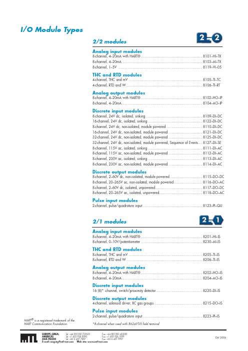
I/O Module Types2/2 modulesAnalog input modules8-channel, 4–20mA with HART® ............................................................8101–HI–TX 8-channel, 4–20mA .............................................................................8103–AI–TX 8-channel, 1–5V ..................................................................................8119–VI–05THC and RTD modules4-channel, THC and mV ........................................................................8105–TI–TC 4-channel, RTD and W ..........................................................................8106–TI–RTAnalog output modules8-channel, 4–20mA with HART® ............................................................8102–HO–IP 8-channel, 4–20mA ..............................................................................8104–AO–IPDiscrete input modules8-channel, 24V dc, isolated, sinking .......................................................8109–DI–DC 16-channel, 24V dc, isolated, sinking .....................................................8122–DI–DC 8-channel, 24V dc, non-isolated, module powered ...................................8110–DI–DC 16-channel, 24V dc, non-isolated, module powered .................................8121–DI–DC 32-channel, 24V dc, non-isolated, module powered .................................8125–DI–DC 32-channel, 24V dc, non-isolated, module powered, Sequence of Events ....8127–DI–SE 8-channel, 115V ac, isolated, sinking .....................................................8111–DI–AC 8-channel, 115V ac, non-isolated, module powered .................................8112–DI–AC 8-channel, 230V ac, isolated, sinking .....................................................8113–DI–AC 8-channel, 230V ac, non-isolated, module powered .................................8114–DI–ACDiscrete output modules8-channel, 2–60V dc, non-isolated, module powered ................................8115–DO–DC 8-channel, 20–265V ac, non-isolated, module powered ............................8116–DO–AC 8-channel, 2–60V dc, isolated, unpowered ..............................................8117–DO–DC 8-channel, 20–265V ac, isolated, unpowered ..........................................8118–DO–ACPulse input modules2-channel, pulse/quadrature input ..........................................................8123–PI–QUAnalog input modules8-channel, 4–20mA with HART® ............................................................8201–HI–IS 8-channel, 0–10V/potentiometer ............................................................8230–AI–ISTHC and RTD modules8-channel, THC and mV ........................................................................8205–TI–IS 8-channel, RTD and W ..........................................................................8206–TI–ISAnalog output modules8-channel, 4–20mA with HART® ............................................................8202–HO–IS 8-channel, 4–20mA ..............................................................................8204–AO–ISDiscrete input modules16 (8)* -channel, switch/proximity detector .............................................8220–DI–ISDiscrete output modules4-channel, solenoid driver, IIC gas groups ...............................................8215–DO–ISPulse input modules2-channel, pulse/quadrature input ..........................................................8223–PI–IS*8-channel when used with 8624-FT-IS field terminalHART ® is a registered trademark of theHART Communication Foundation.I/O Modules - Overview GeneralDefault/Power-up conditionsThese modules use the following values when they power up.Module modeNormal (not “failsafe”)Active/inactiveAll channels power up in the active state.Alarms All alarms are made inactive by having their values set to high or low extremes, as appropriate.Dead Zone0 (i.e. all changes of A/D data are reported for an active channel)Software Filtering Disabled.PassthroughPassthrough messages to HART instruments are always allowed.Visual indicatorsChannel “Status” LED (yellow)An error – i.e. a flashing LED – could be as a result of any of the following conditions:a) a loss of HART signal, b) an error in the A/D converter, c) a NAMUR alarm orAnalog Input Modules - 4-20mAGeneralThe 4–20mA AI modules provide digitised data and status information from 4–20 mA current loop sensors.HART ® capabilityAI modules “with HART” can obtain information from HART instruments of protocol revision 5.0 or later. Each channel can communicate with a single HART instrument. HART universal command 3 is used to gather up to 4 dynamic variables and status from each HART instrument. This provides more process information to the control system from each device. Greater accuracy can also be achieved by eliminating A/D and D/A errors.In addition, HART pass-through may be used for device configuration, calibration and advanced diagnostics.Input samplingThe AI modules have eight user-channels that are sampled every 27ms (2/2) or 33ms (2/1).Data formatThe input signal is stored as a 16-bit unsigned value. In this range 0 is equivalent to 0mA and 65,535 is equivalent to 25mA. Any digital HART data is stored in its original IEEE754 floating point format.FilteringThe Analog Input modules use a first-order software filter that provides 12dB attenuation at the Nyquist frequency of the algorithm. The filter supports a set of options that can be matched with control algorithm execution rates.Input alarmsFour configurable alarm levels are provided for each channel—two high and two low (see figure below). When an input value exceeds an alarm limit a flag is set and the BIM gets a new alarm status.Alarm deadbandThe Alarm Deadband prevents the alarm from tripping on and off because of system noise. It can be configured for each channel and is always set on the ‘inner’ side of the alarm limit to be, typically, greater than the system noise in the plant. If an alarm is activated, it will remain until the input moves the full extent of the deadband towards a “safer” value.The Hi-Hi and Lo-Lo alarms support the NAMUR recommendations, i.e. if the alarm limit is set less than 3.6mA (Lo-Lo), or greater than 21.0mA (Hi-Hi), the alarms must be active for 4 seconds before the alarm is set. The Deadband does not apply to NAMUR alarms. If the alarm limits are set at values between the NAMUR limits, the alarms function normally.Dead zoneEach channel has a definable "dead zone". This is to reduce the need for the module to report to the BIM every minor change in input value. If the input value differs by the amount defined by the Dead Zone, or more, then the new value is reported, otherwise it is not. This reduces traffic on the internal bus which improves the system response time. If the Dead Zone value is set to zero (the default), then every input value read will set a 'New Data' flag, and be reported.Module operating statesNormal/Failsafe modeThe AI modules support failsafe mode as defined in the earlier I/O module introductory section. When not in failsafe the module adopts Normal mode.Channel Active/InactiveA channel can be made active or inactive individually. When a channel is made inactive inputs will not be processed.HART ® is a registered trademark of the HART Communications Foundation.Monitored Channel Value VHi Alarm clearedDeadbandsLo Alarm limitLo Lo Alarm limitHi Alarm limitHi Hi Alarm limitHi Hi NAMUR Alarm clearedTimeInput Value p VHi Alarm setHi Hi Alarm clearedHi Hi Alarm setHi Hi NAMUR Alarm set (4s delay)Lo Alarm setLo Alarm clearedLo Lo Alarm clearedLo Lo Alarm setLo Lo NAMUR Alarm set (4s delay)Lo Lo NAMUR Alarm clearedAnalog Input Modules - THC and RTDInput alarmsThe modules provide two configurable alarm levels for each channel—a high limit and a low one. See figure.When an input value exceeds an alarm limit the appropriate alarm bit (high or low) is set in the channel status byte. In addition, the “new data” signal is set to allow the controller to collect the new alarm status information and the affected channel LED will flash.Alarm deadbandThe alarm deadband (not shown on the diagram) is fixed at 1%.Dead zoneEach channel has a definable "dead zone". This is to reduce the need for the module to report to the B IM every minor change in input value. If the input value differs by the amount defined by the Dead Zone, or more, then the new value is reported, otherwise it is not. This reduces traffic on the internal bus which improves the system response time. If the Dead Zone value is set to zero (the default), then every input value read will set a 'New Data' flag, and be reported.Open sensor detectionWhen configured to do so, the modules will detect an open circuit sensor and report it within 10 seconds. When this occurs a status bit is set in the module and the affected channel LED flashes. The detection options for the two module types are configurable as follows:THC and mVOff, drive upscale or drive downscale RTD and resistance Off or drive upscaleThese choices can be made for each channel.Monitored Channel Value VTimeInput Value pVLo Alarm limitLo Alarm setLo Alarm clearedHi Alarm limitHi Alarm se t Hi Alarm clearedAnalog Output Modules - 4-20mAGeneralThe 4–20 mA AO modules use a single D/A converter in a sample and hold configuration to drive each of the output channels. The processor sets the current value for each of the active channels once every 20ms. Any requested output values below 1mA are clamped to 1mA to ensure that the open-loop detection mechanism is always operable.To verify that active output channels have current flowing to the field, the processor reads a hardware signal every time an output is written to the D/A converter. If the signal indicates “no current flowing”, i.e. < 1mA, for 50 consecutive scans (i.e. one second), an Open-Loop Detection failure is set for that channel.HART ® capabilityAO modules “with HART” are compatible with all HART devices of protocol revision 5.0 or later. Each channel can communicate with a single HART instrument and supports HART communication with the wide range of HART valve positioners now available. HART universal command 3 can be used to gather up to 4 dynamic HART variables such as valve position, air pressure, etc., together with HART status variables. These are scanned by the B IM and may be communicated over the LAN for easy integration into the control system.In addition, HART pass-through may be used for device configuration, calibration and advanced diagnostics.Data formatThe output data has a resolution of 12 bits but is stored as a 16-bit unsigned value. In this range 0 is equivalent to 0mA and 65,535 is equivalent to 25mA.Module operating statesFailsafe mode The module supports failsafe mode as defined in the earlier I/O module introductory section. When put in failsafemode the output can be made to adopt oneof the following options.HART ® is a registered trademark of the HART Communications Foundation.GeneralDI modules can accept up to 8, 16 or 32 discrete inputs, from dry contacts, NAMUR standard proximity detectors, or switched voltages, depending upon module type. The source voltage for field switching can be provided through the module or from an independent supply out in the field.In operation, the input voltage is compared against a threshold voltage to create a ‘true’ or ‘false’ condition. If the inputs are from Zone 2/ Zone 1 or Zone 0 hazardous areas, the appropriate (2/1) module provides certified isolation for these signals.A pulse counter is also included which can count the number of input pulses for each of the channels.Input filterAn input filter can be set individually for each channel to introduce a delay period that allows the input to settle to a stable value.When switched off, the bandwidth of the DI input is 250Hz (100Hz for 2/1 modules). The timeout filter can introduce a timeout delay of between 2 and 512ms in 2ms steps for 2/2 modules and between 3 and 512ms in 3ms steps for 2/1 modules. Alternatively, preset values of “Fast” (22ms) or “Slow” (258ms) may be used.LatchAny channel input can be configured to be “real time” or latched. If the latch feature is enabled, the polarity can also be set so that an input signal that goes:◆high will be held high◆low will be held lowuntil the latch is released by a command from the controller. All channels are latched independently and can be cleared simultaneously, or independently, bya Write instruction to the module’s latch resetregister. If controlled by a BIM this will occurautomatically in 2 to 3 seconds.Line fault detection(2/1 only)When enabled, this will cause a flag to beset to indicate a short or open circuit fault.Low-frequency pulsecounterThe DI modules contain a continuouslyrunning 16-bit pulse counter that countseach low-frequency pulse received on theinput. The maximum pulse rate, with thetimeout filter switched off, depends upon themodule selected; consult the individual datasheets for details. With the filter active, themaximum pulse rate will be determined bythe timeout period used. In order to start aparticular count the counter must be reset tozero by a host instruction. When the counteroverflows (i.e. > 65,536 counts) it willrestart from zero.Module operating states“Failsafe” modeThe module supports failsafe modeas defined in the earlier I/O moduleintroductory section.Channel Active/InactiveEach channel can be made active orinactive individually. When a channel ismade inactive:◆inputs are not processed—i.e. the lastinput value is held and not refreshed◆channel events are not generated◆the counter is not incrementedPower-up conditionsOn power-up, or if a reset is executed,the configuration will automatically adoptpredefined states:Module mode:Normal (not “failsafe”)Channel types:All latches and filters are offActive/Inactive:All channels power-up in the Active stateVisual indicatorsChannel “Status” LED (yellow)On the DI modules the yellow “Status”LED reacts in the following way to moduleconditions.Note: the LED may appear to flash when the inputgoes high and low repeatedly.GeneralDO modules can provide up to 4 or 8 discrete outputs, depending upon module type. Continuous switched loads of up to 1A are directly achievable with these modules. Relays rated at 3, 6 and 10A are also available for switching larger load currents. Line fault detection is provided on the 2/1 modules for both open and short-circuit conditions.Output ModeThe DO module outputs may be configured for one of three different types of output:◆ Discrete◆ Single pulse◆ Continuous pulseDiscreteThe B us Interface Module (B IM) signals an ON or OFF condition on demand.Single Pulse(See Notes 1 & 2)This is an individual “single-shot” action, creating a single ON pulse of specified duration that occurs at a definable time. The pulse on-time can be varied between 2ms and 130s in increments of 2ms. If a new ON command (i.e. trigger) is given during the ON period the pulse will restart. If a new pulse width is supplied during the ON period, it will not take effect until the next ON period.A pulse can experience a small amount of time dither that depends upon the amount of Railbus activity. This can be ± 1% of the pulse width or ± 3.5ms, whichever is the longer.Continuous Pulse(see Notes 2, 3 & 4)This type of output provides a continuous pulse train that is defined by the pulse on-time, and the pulse period (the time between the start of each ON time). The pulse period is configurable to any value between 4 ms and 130,000ms in 2ms steps. The pulse on-time is the same as for the momentary action described above. The on-time must not exceed the setting for the pulse period. (See also the above note regarding AC modules.)Pulses can experience a small amount of time dither that depends upon the amount of Railbus activity. This can be ± 1% of the pulse period, or ± 3.5ms, whichever is the longer. Continuous pulse operation has two distinct modes—static and dynamic. When in static mode, the pulse parameters are cleared from memory when the channel is made inactive; in dynamic mode the values are retained for use when the channel is made active once again.Line Fault detection(2/1 only)When enabled, this will cause a flag to beset to indicate a short or open circuit faulteven when channel output is in OFF state.Module operating statesFailsafe modeThe module supports failsafe modeas defined in the earlier I/O moduleintroductory section, with the following twoadditions:1) Channel using “Configuredfailsafe values”In this mode, the module will force theoutputs to predefined levels— defined on aper channel basis.On entering “failsafe”:a) If channel is in Static mode ofoperation:Pulse mode is disabled and the channelis configured as a latched output and isdriven to its failsafe value.b) If channel is in Dynamic mode ofoperation:If in single pulse (momentary) mode,the configuration is not cleared, but theoutput is driven to its failsafe value.On leaving failsafe:Channel will adopt the mode definedbelow for a channel going frominactive to active state2) Channel using “Hold last value”If the module goes into failsafe during asingle pulse, it is allowed to complete thepulse before adopting the failsafe state. Alatched (discrete) output will remain at itscurrent value.Channel Active/ InactiveEach channel can be made active orinactive individually.When a channel is made inactive the outputis turned OFF (i.e. de-energised).When a channel changes from inactive toactive the following situations apply:a) If channel is in Static mode ofoperation:It becomes a latched output and willremain so until reconfigured by theBIM.b) If channel is in Dynamic mode ofoperation:The channel will resume operation withits previous configuration and output.Power-up conditionsOn power-up, or if a reset is executed,the configuration will automatically adoptpredefined states:Module mode:Normal (not failsafe)Channel typesAll channels are configured as DiscreteoutputsActive/InactiveAll channels power-up in the InactivestateLine fault detection (2/1 only)Disabled on all channelsVisual indicatorsChannel “Status” LED (yellow)On the DO modules the yellow “Status”LED reacts in the following way to moduleconditions.Note: the LED may appear to be flashing wheninput goes high and low repeatedly.Notes:1. This action is only available in Static mode.2. AC modules will react differently to the on-timelength and trigger time. The module can onlybe triggered ON during a zero crossing ofthe AC waveform; similarly, the module canonly switch OFF at a zero crossing point. Theminimum on-time is therefore restricted to halfthe total period of a regular waveform.3. Continuous pulse operation is supported onlyby Version 2 models of BIMs 8502 and 8505.4. On 2/2 modules, this action is only availablein Static mode.Generalto measure:◆frequency◆acceleration / rate◆number of pulses (i.e. counter)When combined, they provide:◆rfrom quadrature encoding devices outputs and one digital input to gate (start/ stop) the channel 1 internal counter. Pulse inputsInputs types accepted are:◆P roximity detectors(NAMUR/DIN19234)◆ Current inputs◆ Voltage inputs◆Switch / electro-mechanical inputs input can be set to suit the application. Dynamic datachannel, from the signal pulses received. FrequencyThe default is the rising edge.There are ten frequency measurement ranges.should be considered as “out-of-range”. Accelerationnegative value is a decrease in the rate.FilteringThe module has a hardware filter which can be used to minimise the effects of contact bounce. The available settings are 1, 5, 20 kHz and Off.AlarmsHigh / Low alarmsHigh and low alarms can be configured for each channel. When the input value goes beyond an alarm limit, channel and module flags are set, the channel LED flashes and, if configured, the channel’s digital output state will change.Acceleration alarmsAn acceleration alarm limit can also be set. If the limit is exceeded the actions taken are identical to those for the high/low alarms. Alarm deadbandA deadband can be specified for the high, low and acceleration alarms. This provides hysteresis to avoid repetitive alarms in noisy signal environments.Missing pulse alarmBoth channels can be configured to detect a “missing pulse”. If no input pulse is detected for a defined time period an alarm is signalled in the same way as the high/low alarms.The alarm is cleared on receipt of a pulse or on reconfiguration of the alarm. The time period is restarted after each sample period in which at least one pulse occurs.Line Fault DetectEach channel can be configured to sense an open or a short circuit condition on inputs. On detection, the actions are those for the high/low alarms.On fault, the BIM can: report the frequency value as being at the top or the bottom of the range, freeze the counter, set the acceleration to zero; depending on how the BIM is configured.Control dataThe host can write data to control each channel counter. The available parameters are: start, stop, set, reset and preset value. Digital outputsB oth digital output channels can reflect the status of the inputs by indicating:◆frequency or acceleration alarm◆counter preset value reached while themain channel can also output:◆quadrature forward or reverse signal◆scaled retransmission (a “divided by N” version of the input)Pulse Input Modules - 2-channel pulse/quadratureGeneralSequence of Events (SOE) recording is used to capture each of the events that occur during a shut-down or trip sequence. Such information is invaluable in determining the cause of such an event.In the course of such a sequence, events often take place very rapidly throughout the process area. The SOE module and its companion Event Logger software provide a means for recording these events and, because highly accurate time stamps are used, the precise order in which they occurred can be determined.8127-DI-SE is a 32-channel SOE module designed to monitor the status of digital inputs and to record any state changes to an internal buffer. Each state change is time-stamped to the nearest ¼ millisecond.The contents of the buffer are periodically transferred to the controller. Each module has a buffer capacity of 512 events, which it can transfer to the controller in about 500ms, consequently, approximately 1000 events per second can be captured.SOE Event Logger software The Event Logger software is provided with all MOST Workbench products. This software collects time-stamped data from the controller and merges information from multiple controllers into a chronological journal before exporting the data to standard event viewers, such as Wonderware’s InTouch. Other data export options include OPC Event format or a basic text file.The event logging software can also be used to record events other than SOE activity. For example, it can be used to record changes of state in the controller, such as when control is switched between master and slave controllers. It could be used to record when an analogue limit has been exceeded or when a digital module changes state. This powerful capability enables all critical events in the process to be recorded, providing a complete picture for further analysis.Sequence of Events ModuleBenefits◆ More accurate event sequencingAll logged events are time stamped using 1/8ms resolution for 1/4ms accuracy. The controller uses Network Time Protocol (NTP) to assure time stamp accuracy between modules across the network. When using NTP, all controllers are synchronized across the network to ± 3ms, resulting in very accurate event sequencing.◆ Identify problems quicklyEach SOE input has a unique line-fault detection feature to identify a short circuit or open circuit on each input. Problems are identified immediately for correction, saving considerable maintenance time.◆ Simplifies field wiringField circuits are module-powered, eliminating the need to “daisy chain” power supply wiring at field terminals. Field circuits are powered with a minimum of wiring and termination effort.◆ Locate SOE modules in the process Like the rest of the control platform, SOE modules can be located in your process, next to your field devices in order to record events locally on a more reliable & timely basis.◆ Easy integration with otherapplicationsEvents from multiple modules and controllers can be stored in a single SOE Event Logger providing an easy interface to other applications. 32 Discrete ChannelsThe 8127-DI-SE has 32 discrete input channels and each channel can be configured as either an SOE input or a standard discrete input.SOE input signals can also be used as standard discrete inputs as part of any control strategy. Each module can buffer up to 512 events.Events are communicated to the controller, which uses Network Time Protocol (NTP) to accurately convert the module’s time stamp data to real time. The SOE Event Logger, which constantly polls the controller for new events (typically every 2 seconds), collects each time-stamped event. After recording the events, the Event Logger sends an acknowledgement to the controller, which then clears the event from its memory.The controller retains all events until all active Event Loggers acknowledge them. Multiple Event Loggers can be used for redundant event recording and will always have consistent time stamps since all events are time stamped by the controller.Events are displayed by the SOE Data Retrieval Client. Following data retrieval, the user can choose to email the SOE data, Print it or Save it to a CSV file. The user can create a custom report easily by selecting thecolumns to be viewed and printed.See also the 8618-FT-MT field terminal for custom termination options.8-channel Analog Input◆ 8 single-ended 4-20mA input channels ◆ non-incendive field circuits ◆ HART pass-through◆ HART variable and status reporting ◆ 2- or 4-wire transmitters ◆ open and short circuit detection ◆ 24V dc bussed field power required MODULE SPECIFICATIONSee also System SpecificationINPUTSNumber of channels .......................................8, single-ended Nominal signal range (span) ...............................4 to 20mA Full signal range ...................................................1 to 23mA Line fault detectionShort circuit current .....................................................> 23.5mA Open circuit current ......................................................< 0.5mA Output voltage (@ 20mA) ...................................13.5V (min.)Output current ..................................................32mA (max.)Accuracy (over temp range) .........................± 0.1% of span Resolution ....................................................................16 bits Repeatability ....................................................0.05% of span Isolation(any channel to Railbus).................................................100V ac (between channels) .............................................................noneCONFIGURABLE PARAMETERSAlarms ....................................high, high-high, low and low-lowAlarm deadband (hysteresis ) er defined value Input filter time constant er defined value Input dead zone er defined value Drive on failsafe ...................... disabled /upscale /downscale Channel status ................................................ active /inactive HART variable and status reporting ........... enable /disableRESPONSE TIMESignal change to availability on Railbus4–20mA mode ........................................................27ms (max.)HART mode .....................................................0.75s per channelSAFETYFM non-incendive field wiring parameters (each channel) ....................V oc = 28.7V; I sc = 33mA; C a = 0.17µF; L a = 11.0mHPOWER SUPPLIESRailbus (12V) current .......................................100mA (typ.) ...........................................................................150mA (max.)Bussed Field Power 2-wire Tx .......................300mA (max.) (@ 24V dc ±10%) 4-wire Tx .........................60mA (max.)MECHANICALModule Key Code .............................................................A1Module width ...............................................................42mm Weight ............................................................................200g4–20mA with HART®8101-HI-TXFIELD TERMINALS (2-WIRE TX)FIELD TERMINALS (4-WIRE TX)HART ® is a registered trademark of the HART Communication Foundation.。

托利多wm-0800中文说明书V1.3METTLER TOLEDO WEIGHTSMITTER 操作简介功能键隐藏于METTLER TOLEDO商标图案中的菱形处。
WM-0800重量变送器是梅特勒-托利多公司专为各类工业应用场合设计的高品质产品,采用电荷下图每项前的三个符号自上而下分别表示重量变送器面板上的三个指示灯OVER / POWER / 平衡式模数转换及数字滤波处理技术,消除了模拟电路型的重量变送器所固有的时飘及反复标定UNDER。
三个符号中的 0表示该灯熄灭 / 1表示该灯亮 / X表示该灯闪烁。
现象。
当重量变送器处于下表中以阴影提示的六种状态之一时,重量变送器的上下限(OVER / UNDER)WM-0800重量变送器通过对称重传感器(组)输出的弱重量信号进行数字处理,输出相应的报警均输出报警信号。
重量变送器在使用前应进行空秤点及加载点的模拟量输出调整. 4~20mA/0~10V模拟量电信号至用户的上位系统。
同时,WM系列重量变送器向现场提供两个输出点:0 上限报警与下限报警, 1 正常工作变送器模拟量输出值应比例对应于秤体上的 0 WM-0800重量变送器非本质安全型设备,必须工作于安全场合或采取隔爆措施,在联接危险区重量值(4mA/0V对应于空秤;20mA/10V对应于0的称重传感器需使用安全隔离栅。
欠载报警(即当前模拟量输出满秤量),否则需进入设定项进行输出调整。
1 值小于所设定的欠载报警点) 1 技术指标按功能键并保持三秒钟则进入设定项目(下1 面的四项即为设定项目)。
超载报警(即当前模拟量输出电源要求:24VDC?4VDC, 0.3Amp 1 值大于所设定的超载报警点) 0 称重接口:激励电压为5VDC,最多可接4只350欧姆的电阻应变式称重传感器1 调整空秤点的模拟量输出四个调整键(增大、快增大、减小、快减小)量程信号范围:1mV至15mV / 零点信号范围:1 mV至12mV 1 (执行本步骤需保持空秤状态,可调整模拟量输出值,持续按键可进行加速调模拟量电压输出:输出范围为0~10VDC,负载电阻最小为10,000欧姆 X 再用调整键调整至4mA/0V点) 整过程;点按功能键可在各设定项之间切换; 模拟量电流输出:输出范围为4~20mA,负载电阻最大为500欧姆调整加载点的模拟量输出每个设定项调整完毕后,均需再按功能键并(执行本步骤需在秤上加载一整体输出精度:?0.03%的满秤量(20?时) X 保持三秒钟以存入新的设定值,同时变送器退已知重量,并根据秤载与输出模 1 工作温度范围:-10? to +45? 出设定项目; 拟量的比例关系计算出理论上的 1 误操作调整键之后,可点按功能键直至退出存储温度范围:-30? to + 70? 模拟量输出值,再用调整键调整设定,变送器不保存设定值; 至理论输出值) 湿度范围:10%~95% (无冷凝) 如三十秒钟内未有任何键操作,则变送器自0 调整欠载报警点的模拟量输出防护等级:IP65级(防水、尘溅射) 行退出设定状态,也不保存设定值。

EUROPE (EMEA)Tel: +44 (0)1582 723633 Fax: +44 (0)1582 422283AMERICAS Tel: +1 603 926 0090Fax: +1 603 926 1899ASIA PACIFIC Tel: +65 487 7887Fax: +65 487 7997E-mail:***************************:June 2004MTL3072 TEMPERATURE CONVERTER3-wire RTD inputSPECIFICATIONSee also 'Common specification'Number of channelsOne, fully floating Signal source3-wire platinum RTD to BS1904/DIN 43760 (100Ωat 0°C) –terminals 5, 6 & 7Location of signal sourceZone 0, IIC, T4 hazardous area if suitably certified Div 1, Group A, hazardous locationSpan (fully adjustable by switches and potentiometers)25 to 800°CZero (fully adjustable by switches and potentiometers)–200 to +400°CCommon-mode ac rejection<0.1% error for 250V rms, 50Hz Series-mode ac rejection<0.1% error for 50Hz rms input equal to 2mV or (span in Ω/30)mV, whichever is the greater Loop supply voltage15 to 35V dc Output range4 to 20mAMaximum load resistance50(Vs –15) ΩResponse timeSettles to within 10% of final value after typically 250ms Calibration accuracy at 20°C(including non-linearity, hysteresis and repeatability)Within 0.1% of spanTemperature drift (maximum)Zero:the greater of the following:–±0.01% of span/°C or 10m Ω/°C Span:±0.005% of input span/°CSuppression/elevation (E):±0.01% of E/°C RTD excitation current400µALine resistance100Ωmaximum in each line Power dissipation within unit0.46W maximum at 35V with 20mA signal Replaceable fuse50mA, 5 x 20mm glass to DIN 41571 sheet 2, semi-time-lag (M)Safety description13.6V, 142Ω, 95.3mA, C eq = 56.5nF , L eq = 2.2mH, U m = 250V rms or dcFM max entity parametersV oc = 13.6V, I sc = 95.3mA, C a = 1.15µF , L a = 1.8mH Weight170gThe MTL3072 accepts a signal from a 3-wire resistance temperature detector (RTD) in the hazardous area, and converts it to a 4/20mA loop current in the safe area proportional to resistance (but not temperature). Calibration is carried out by the user via controls located in the top and the side of the unit. Input zero and span are selected by switches (coarse adjustment) and potentiometers (fine adjustment).OTHER APPLICATIONSThe MTL3072 can monitor a low-value potentiometer, up to 375Ω, in a hazardous area to give a 4/20mA output in the safe area .。

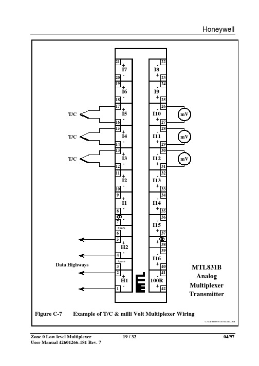
Eaton Electric Limited,Great Marlings, Butterfield, Luton Beds, LU2 8DL, UK.Tel: + 44 (0)1582 723633 Fax: + 44 (0)1582 422283E-mail:********************• Reduce the cost of installing hazardous-area cabling• Save installation time, space and weight • Highlight problems quickly with status reporting systems• Protect the process with sensor failure detection and safety drives • Connect directly to host systems through serial-data outputs• Analogue inputs to controllers with Modbus® communications •Redundant data highwaysMTL830 rangeMultiplexers for Zone 0 hazardous area applicationsMTL830 range of multiplexers with Modbus ® outputs provide a cost-effective alternative to single-loop isolation. The cost of installed wiring is reduced by up to 50% by communicating the input of multiple hazardous-area sensors over dual-redundant data highways. Further savings are achieved by reducing the number of inputs to the host, cabinet space and weight.A multiplexer transmitter, mounted in the hazardous area, catersfor thermocouple, RTD and mV analogue inputs. A compatible safe-area receiver provides serial Modbus® outputs for feeding to hostPLC, PC or DCS controllers.Dual-redundant data h igh ways between the transmitter and thereceiver allow continuous normal operation with only one highwayconnected. The highway cable, a simple twisted pair or a pair ofwires within an IS multi-core cable, carries both power and data, over distances up to 2km. If the multiplexer transmitter is located in the hazardous area, each data highway must be protected by an MTL3052 digital isolator.Multiplexer systems can communicate the status of up to 32 inputs, reducing the number of hazardous area wiring pairs from 32 to two.Reduce costs by eliminating long runs of expensive thermocouple compensation cable from the hazardous to the safe area. AIso, if 3- or 4-wire RTDs are used, costs are reduced by terminating each RTD at the transmitter or its enclosure.Dual redundant h igh ways increase system reliability. Failuredetectors and safety drives protect against the consequences ofsensor failure, while built-in systems report failures to the hostcontroller.Accessories include steel and stainless-steel enclosures, earth-leakage detectors and a PC-based configuration software package.For more information see AN9010, ‘A user’s guide to multiplexers’ and TP1098, ‘Cut the cost of intrinsic safety – by multiplexing!’The given data is only intended as a product description and should not be regarded as a legal warranty of properties or guarantee.In the interest of further technical developments, we reserve the right to make design changes.MTL831B multiplexer transmitters are normally sited in the hazardous area. They are connected to sensors in the field and communicate these inputs to the safe area via single-pair data highways. The data highways support communication between the safe and hazardous areas,and also provide power to the transmitters – no additional field power is required.The MTL831B would typically be mounted close to the field instruments in an enclosure such as the ENC8 or ENC83 (see 'MTL800 range of Enclosures').MTL831B ANALOGUE INPUT TRANSMITTERMonitors inputs from up to 16 THC or millivolt sources (max ±60mV) or up to 15 2-, 3- or 4-wire RTDs within a hazardous area.• Intrinsically safe; Zone 0 location• Communication and power pass over twin data highways • Powered by the data highway•Thermocouples and RTDs may be mixed on one transmitterMUL TI-DROPPING TWO MTL831BSTwo MTL831B multiplexer transmitters can share the same single-pair highway to a single safe-area isolator/receiver combination, providing up to 32 multiplexed inputs.DATA HIGHWAY CABLINGCabling with low capacitance and resistance is recommended to achieve greater distances between transmitters and receivers. See cable parameters in 'Basic Specifications' for specific requirements, and contact Eaton's MTL product line for latest cable recommendations. The system is designed to use both data highways, although it can be used with only one data highway in place. However, use of a single highway will increase response time.Data highway lengths of up to 2km in hazardous areas and 3km in safe areas have been achieved.ENCLOSURESA range of steel and stainless steel enclosures is available for mounting MTL831B units in the field (see 'MTL800 range of Enclosures'). ENC8 and ENC8SS (stainless steel) enclosures provide protection for a single MTL831B. The enclosures are dust-tight and waterproof to IP67.When using 4-wire RTDs, ENC83 and ENC83SS (stainless steel) enclosures provide additional terminals to accommodate the third and fourth RTD wires, which are not connected to the MTL831B itself.MTL838B-MBF receivers translate the information transmitted from the MTL831B via the data highway. The MTL838B-MBF provides a Modbus® serial-data output representation of the inputs together with status information.MTL838B-MBF MODBUS® ANALOGUE RECEIVERTranslates data received from the MTL831B in the hazardous area and makes it available as twin RS485 Modbus® serial data outputs. The MTL838B-MBF is configured by personal computer for thermocouple and RTD type, safety drive, high and low alarm and any other operational parameters.MTL3052 DATA HIGHWAY ISOLATORAn MTL3052 isolator is required for each data highway, when the transmitter is located in a hazardous area. It is not required for safe-area applications.MUL TI-DROPPING MODBUS® RECEIVERSUp to 31 Modbus receivers can be multi-dropped on a single RS485 link to the host system. Modbus® receivers can be controlled by any suitable Modbus® master. The receivers may be used with other Modbus® slaves on the same RS485 link.The given data is only intended as a product description and should not be regarded as a legal warranty of properties or guarantee.In the interest of further technical developments, we reserve the right to make design changes.The given data is only intended as a product description and should not be regarded as a legal warranty of properties or guarantee.In the interest of further technical developments, we reserve the right to make design changes.BASIC SPECIFICATIONS(see also 'Common specification')MTL831B (mV input)Number of input channels 16 THC or mV sources, potentiometer inputs up to 1kΩ)15 (RTD or mixed)(IS segregated and fully floating when used with MTL3052)Location of input sources Zone 0, IIC, T4Location of unitZone 0, IIC, T4Number of data highways Dual redundant (either or both)Power requirementLoop-powered through data highway from receiver No hazardous-area power supply required Multi-transmitter facility 1 or 2Ambient temperature limits–20 to +60°C working –40 to +80°C storage Weight1.3kgTypical response time 1s for each transmitter (input to receiver output)Electrical safety (each input circuit)U max:out = 15V I max:out = 16.3mA W max:out = 60mWInput sensor cable parameters BASEEFA values (C,L or L/R)(IIC)0.58µF,127mH or 535µH/Ω(IIB) 3.55µF, 486mH or 1087µH/Ω(IIA)14µF, 903mH or 1087µH/ΩElectrical safety (data highwaycircuit[s])U max:in = 30V maximum input parameters I max:in = 300mA W max:in = 1.2W C eq = 0, L eq = 0ADDITIONAL SPECIFICATIONSMTL831BEach input terminal block is user-selectable by switch for mixed mV, THC, 2- or 4-wire RTD input or 3-wire RTD input.Measuring ranges±60mV or ±25mV or ±10mV, auto ranging Common mode voltageMaximum 5V common mode between input channels of one transmitter mV signalsAccuracy at 20°C (including non-linearity and hysteresis)<0.1% of measuring rangeTemperature effects on accuracy {(greater of 0.01% of range or 2µV) + 0.01% of reading} /°CThermocouple signalsAccuracy at 20°C (including non-linearity and hysteresis)<0.1% of measuring range ±0.7°CUpscale/downscale drive does not introduce any accuracy errors Temperature effects on accuracy{(greater of 0.01% of range or 2µV) + 0.01% of reading + 0.03°C}/°C RTD signalsRTD range–200 to +850°C (Pt100 type, DIN 43760, IEC751: 1983)RTD excitation current 100µAAccuracy at 20°C (including non-linearity and hysteresis)<0.1% of measuring rangeTemperature effects on accuracy{(greater of 0.01% of range or 0.025°C) + 0.005% of reading}/°CThe given data is only intended as a product description and should not be regarded as a legal warranty of properties or guarantee.In the interest of further technical developments, we reserve the right to make design changes.BASIC SPECIFICATIONS(see also ‘Common specification’)MTL838B-MBF (Modbus® output)Number of data highways 2, dual redundant (either or both may be used)Location of unitSafe areaInput noise rejectionUp to 0.5mA peak-to-peak at 100 to 1000Hz, or up to 1mA peak-to-peak at 50HzType of output(s)Dual RS485 Modbus® protocol System protocolModbus® ASCII or RTU Serial communication parametersBaud rate: 300 to 19200Stop bits: 1 or 2Data bits: 7 or 8Parity bit: odd, even or noneMulti-receiver facilityUp to 31 MTL838B-MBF units can be connected to communicate with one Modbus® master controller Power requirement500mA at 20–35V dc Ambient temperature limits –20 to +50°C working –40 to +80°C storage Weight840gADDITIONAL SPECIFICATIONSMTL838B-MBFThermocouple range supportedTypes E, J, K, N, R and T THCs to IEC 584. Other options are available, please contact Eaton's MTL product line for details.System configurationSerial communications parameters and system parameters entered using PCS83 software program, by downloading from process controller. Configuration parameters are retained by using battery-backed RAM.LinearisationMulti breakpoint calculation by microprocessor (output is linearised and cold junction compensated)Broken THC indicationSerial output drives upscale or downscale Alarm facilitiesHigh and low alarms are indicated in the serial data and can be set for each inputThe given data is only intended as a product description and should not be regarded as a legal warranty of properties or guarantee.In the interest of further technical developments, we reserve the right to make design changes.This unit is similar in principle to the MTL3042 but operates at a higher frequency for use with digital signals. Its primary application is to provide IS protection for the data highways and transmitters in MTL800 range of multiplexer systems. The MTL3052 features two output circuits: one with a 15V, 180Ω safety description, and an alternative 15V, 100Ω circuit which can be used if higher loop resistances need to be accommodated, for example when surge protectors are incorporated in the data highways. If the low-resistance outputs are used on two units fitted to a dual-highway system however, the multiplexer transmitters are restricted to location in IIB atmospheres.SPECIFICATIONSee also 'Common specification'Number of channelsOne, fully floating Location of loadZone 0, IIC, T4–6 hazardous area if suitably certified Div 1, Group A , hazardous locationZone 0, IIB, T4–6 (Div 1, Group C, hazardous location)for multiplexer transmitters in dual-highway systems using the low-resistance outputs of two MTL3052s Input voltage4 to 12V dcSignal bandwidthdc to 10kHzMinimum output voltage[V in minus (0.25 x current in mA)] V Input and output circuit ripple<1mA peak-to-peakPower dissipation within unit160mW maximum at 12V with 20mA signal Replaceable fuse50mA, 5 x 20mm glass to DIN 41571 sht. 2, semi-time-lag (M)‘No-fail’ earth fault protection (optional)Enabled by connecting terminal 8 to MTL4220Fault on either line proclaimed: unit continues working Safety descriptionTerminals 5 & 615V, 100Ω, 150mA, U m = 250V rms or dc Terminals 7 & 815V, 180Ω, 83.3mA, U m = 250V rms or dc FM max entity parametersV oc = 15V, I sc = 83.3mA, C a = 0.75µF, L a = 5.2mH Weight130g Cable parameters - BASEEFA values (data highway circuits, each highway)Terminals 7 & 8Terminals 5 & 6Grp C µF L mH L/R µH/ΩC µF L mH L/R µH/ΩIIC 0.58 5.21090.58 1.6565IIB 3.5515.6327 3.55 4.95195IIA1441.68721413.2520OTHER APPLICATIONSThe MTL3052 is suitable for a variety of other applications, such as bringing back the status of a hazardous-area mechanical or opto-transistor switch, or a magnetic shaft encoder (all via suitable current limiting resistors).The given data is only intended as a product description and should not be regarded as a legal warranty of properties or guarantee.In the interest of further technical developments, we reserve the right to make design changes.Maximum loop impedance (each data highway)50Ω when using MTL3052 interface (terminals 7 & 8)130Ω when using MTL3052 interface (terminals 5 & 6)300Ω for non-IS applicationsTransmission distance (transmitter to receiver)0.5km typically (IS applications)1.5km typically (non-IS applications)For many applications it is possible to use longer distances up to 3km, for details consult Eaton's MTL product line Intrinsically safe interface (IS applications)1 MTL3052 isolating interface unit for each data highway Earth fault protection (optional)An optional MTL4220 earth leakage detector will detect line-to-earth faults on either line of either highway.Data highway monitoringHighway 1 LED, green (located on receiver)ON when highway 1 connected and operating Highway 2 LED, green (located on receiver)ON when highway 2 connected and operating Highway 1 & 2 statusSerial output receivers: condition of highway(s) transmitted in unit status word to process controller System failure monitoringSystem failure LED, red (located on receiver)ON when both highways disconnected or faulty or when there is an internal receiver fault System failure signalSerial output receivers: derived from status word Power supply failureAll relays and LEDs de-energiseHumidity5–95% RH (without condensation)EMC complianceEN 50081-2/EN 50082-2, generic emission/immunity standards. These refer to appropriate IEC/CISPR standards.TerminalsDetachable, each accommodates two 2.5mm2 conductors CasingsMoulded polycarbonateCONDITIONS OF USEThe conditions governing the use of MTL800 range of multiplexers are given in the relevant certificates and schedules, copies of which are available from Eaton's MTL product line.DIMENSIONS (mm)(in extended position)The given data is only intended as a product description and should not be regarded as a legal warranty of properties or guarantee.In the interest of further technical developments, we reserve the right to make design changes.SPECIFICATIONSENC8/ENC8SS: for 1 MTL831B transmitter, or 1 MTL838B receiverENC83/ENC83SS: for 1 MTL831B transmitter (for use with 4-wire RTDs)LocationZone 0, 1 or 2ProtectionDust-tight and waterproof to IEC529:IP67Construction (ENC8 and ENC83)Sheet steel, zinc sprayed and painted RAL7015 grey Construction (ENC8SS and ENC83SS)Stainless steel LidDetachable with lift-off hinges, secured by captive fixing screws with a padlock hasp Earth terminalsFitted on internal earth rails; accommodate conductors up to 4mm2Number of earth terminalsENC8/ENC8SS: 22ENC83/ENC83SS: 184-wire RTD terminals (ENC83/ENC83SS only)32 ready-mounted terminals to accommodate conductors up to 4mm2Gland fixingTop and bottom gland plates detachable for drilling by user MountingBy fixed mounting lugsWeight (excl. transmitters/receivers)ENC8: 7kg ENC83: 9.8kgDIMENSIONS (MM)SPECIFICATIONSPCS83 software package (for MTL838B-MBF)Function : Software configuration of multiplexer system Format : 3.5 inch diskette Requires: PC with DOS 2.2, or higher, and a serial (COM) port.TO ORDER, SPECIFY:Transmitters MTL831B Analogue transmitter ReceiversMTL838B-MBF Analogue receiver, RS485 and/or RS422outputs for Modbus®Analogue receiver accessoriesPCS83 PC software configuration package Process controller interface softwareContact Eaton's MTL product line for details of software for interfacing with proprietary process controllersIsolating interface units and earth leakage detectorsMTL3052 Digital isolator interface unit MTL4220 Earth leakage detector EnclosuresENC8 General-purpose enclosure ENC8SS General-purpose enclosure (stainless steel)ENC83 Enclosure for MTL831B transmitter ENC83SS Enclosure for MTL831B transmitter (stainlesssteel)LiteratureINM838B-MBF System protocol manual: MTL838B-MBF Modbus® receivers INM831B MTL831B manual AN9010 Application Note: A user's guide to intrinsicallysafe input multiplexer systemsINS831B MTL831B mV Multiplexer transmitter INS838B MTL838B-MBF Multiplexer receiver - Modbus®outputAB C D ENC8331306203306ENC83407380305466。
Quick Start GuideQSG 800LTWIO-800LTwireless I/O transmitter unitABOUT THIS DOCUMENTThis is the Quick Start Guide for the MTL WIO-800L T Wireless I/O TransmitterUnit and contains the following sections:For more information, see the following sections.1 Basic steps for using your unitThis document describes how to configure your unit using the default factoryconfiguration that lets you easily setup your network as a simple send/receivenetwork using a dedicated pair of transmitter and receiver units.The basic steps for using your unit are:1. Connect the antenna power supply and transducer signals using theinstructions in this document. Power supply and transducer connectionis described in the section Unit components and connections. Antennaconnection is described in the section Antenna installation. For moreinformation, see the WIO-800L Installation Manual.2. Reset the transmitter and receiver units to the factory default configurations.3. Link the transmitter and receiver units to work as a dedicated pair.4. Bench test your configuration before deploying.NOTE: You can also configure your network using a user-defined customisedconfiguration that lets you set specific information about your network. Formore information on setting a user-defined customised configuration, see theWIO-800L User Manual on the enclosed CD.2 Factory default configurationWhen you configure the units using the configuration in this document, the2QSG 800LT-1.7May 20103QSG 800LT-1.7May 20103 Unit components and connectionsYour WIO-800LT transmitter unit has the following components and terminal connections:S Y S T E M O KS P S T A T U SC O M M O NA N A L O G L O O P S U P P L YP O W E R S U P P L Y+ +24V +C O M M O NC O M M O N++D I 1D I 2A IT H E R M O C O U P L E /m V ++LOAD LOAD++Max. 30V DC500mAFor inductive load,use surge diodesPOWER SUPPLY 9 - 30V DC 250mA @ 12V 125mA @ 24VEarth / ground wireterminal on reverse sideThermocouple type J, K or T or mV signalLoop powered sensor shown.External powered sensors are also suitableDIs suitable for volt-free contacts or NPN transistor devices4QSG 800LT-1.7May 2010The front panel provides the following components: The triangle on the rotary switch indicates the current position, for example:Position 0 or Position 3NOTE: To avoid damaging the rotary switch, use a screwdriver to change the position.The rotary switch uses the following setpoint levels:The LEDs on the front panel indicate the unit status:at top of unitRS232 configuration portswitch5QSG 800LT-1.7May 20104Antenna installation5 Resetting your unit to factory defaultsYou must reset the receiver unit to factory defaults before linking thetransmitter and receiver units.To reset the default factory configuration:1. Set the RSSI rotary switch to position 0 using a screwdriver.2. Power on the WIO-800LT transmitter.3. The WIO-800LT transmitter flashes all LEDs at medium flash (i.e. 1.6 Hz).NOTE: If the LEDs do not flash, you must repeat steps 1 and 2 until the LEDsflash before continuing.4. Set the RSSI rotary switch to another position (e.g. position 1) within 5seconds.5. Set the RSSI rotary switch to position 0 within another 5 seconds.6. The WIO-800LT transmitter lights all LEDs for 2 seconds before returningto normal operation.NOTE: If the LEDs do not light, you must repeat the process from step 1 untilthe LEDs light before continuing.7. You can now link the transmitter and receiver units.6 Linking your transmitter and receiver unitsYou must reset the transmitter unit to factory defaults (to disable encryption)before linking the transmitter and receiver units. For more information, seethe previous section.NOTE: You must complete the linking process in 60 seconds.To link the transmitter and receiver units:1. Press and hold down the RSSI Pushbutton on the receiver.2. Power on the receiver while holding down the RSSI Pushbutton3. Release the RSSI Pushbutton as soon as the Receiver LEDS flash (within5 seconds of powering the receiver).4. The receiver will flash all LEDs for a maximum 60 seconds while it tries tolink to the transmitter.5. Power on the transmitter. The transmitter sends a special “Link” messageto allow the receiver to recognise the transmitter.6. When the units link, the receiver lights all LEDs for 2 seconds beforereturning to normal operation.NOTE:If the receiver LEDs continue flashing within the 60 seconds, theunits are not linked and you should retry the linking process by powering thetransmitter off and on again. If you exceed the 60 seconds, you must restartthe linking process from step 1.You can now bench test your configuration before deploying.6QSG 800LT-1.7May 20107QSG 800LT-1.7May 20107 Safety informationThank you for selecting the WIO-800LT transmitter for your telemetry needs. We trust it will give you many years of valuable service. To ensure your WIO-800LT transmitter enjoys a long life, double-check ALL your connections with the user’s manual before powering on the unit.WARNING: Incorrect termination of supply wires may cause internal damage and will void warranty.8Unit specificationsGroup Internet home page /Members of The MTL Instruments GroupMTL Instruments Pty Limited 9 /12 Billabong Street StaffordQueensland 4053AustraliaTel: + 61 1300 308 374 Fax: + 61 1300 308 463E-mail:********************.auCooper Electric (Shanghai) Co. Ltd.Room 2001, China Life Tower 16 Chao Yang Men Wai Street Chao Yang District, Beijing China 100020Tel: + 86 10 5980 0288 Fax: + 86 10 8562 5725E-mail:*******************MTL Instruments sarl Les Carrés du Parc 10 rue des Rosiéristes69410 Champagne au Mont d’Or FranceTel: +33 (0)4 78 64 98 32 Fax: +33 (0)4 78 35 79 41E-mail:****************MTL Instruments GmbH An der Gümpgesbrücke 17D-41564 Kaarst GermanyTel: +49 (0)2131 718930 Fax: +49 (0)2131 7189333E-mail:***********MTL IndiaNo. 36, Nehru StreetOff Old Mahabalipuram Road SholinganallurChennai - 600 119IndiaTel: + 91 (0)44 24501660/24501857 Fax: + 91 (0)44 24501463E-mail:******************MTL Italia srl Via Cantù 11I - 20092 Cinisello Balsamo MI ItalyTel: +39 (0)2 61802011 Fax: +39 (0)2 61294560E-mail:****************Cooper Crouse-Hinds Japan KK MT Building 3F2-7-5 Shiba Daimon Minato-ku Tokyo Japan 105-0012Tel: +81 (0)3 6430 3128 Fax: +81 (0)3 6430 3129E-mail:**************.jpCooper Crouse-Hinds Korea 12F, Vision Tower707-2 Yeoksam-dong, Gangnam-gu Seoul 135-080South KoreaTel: +82 2 3484 6795 Fax: +82 2 3484 6778MTL Instruments BV MTL Instruments BV Terheijdenseweg 4654825BK Breda The NetherlandsTel: +31(0)76 7505360 Fax: +31(0)76 7505370E-mail:*******************Cooper Crouse-Hinds Pte Ltd.No.2 Serangoon North Avenue 5#06-01 Fu Yu Building Singapore 554911Tel: +65 6 487 7887 Fax: +65 6 487 7997E-mail:*****************.sgMTL InstrumentsVilla No. 4, Sector 2-17, Street 6PO Box 53234,Abu Dhabi, UAETel: +971 2 446 6840 Fax: +971 2 446 6841E-mail:********************Measurement Technology Limited Great Marlings, Butterfield, Luton, Beds England LU2 8DLTel: +44 (0)1582 723633 Fax: +44 (0)1582 422283E-mail:********************Cooper Crouse-Hinds MTL Inc 3413 N. Sam Houston Parkway W.Suite 210Houston TX 77086USATel: +1 281 571 8065 Fax: +1 281 571 8069E-mail:*******************。
MOD800系列数据转换装置说明书V1.4许继电气二○○九年九月*本说明书可能修改,请注意最新版本目录一、概述 (1)二、主要特点和技术参数 (1)1、主要特点 (1)2、技术参数 (1)三、电路说明 (2)1、模拟通道(MODEM) (2)2、数字通道(DIGIT) (2)四、参数及功能设置 (3)1、模拟通道 (3)2、数字通道 (7)五、原理及机构说明 (8)1、MOD800A(单入单通道输出) (8)2、MOD800B(双入单通道输出) (9)3、MOD800C(单入双通道一数一模拟输出) (11)4、MOD800D(单入双通道输出) (12)5、MOD800E-1(双入双出双通道切换方式—双模) (13)6、MOD800E-2(双入双出双通道切换方式—1数1模) (15)7. MOD800F(双数字通道切换方式) (17)六、注意事项 (19)七、设备选型(输出数字接口默认为RS232,如选用RS422方式须在订货时说明,涉及到MOD800C-1、MOD800C-2、MOD800E-2、MOD800F四种型号) (19)附表1(端子定义图) (21)1、模拟通道口定义 (29)2、数字通道口定义(RS-232) (30)3、数字通道口定义(RS-422) (30)4、电源端口定义 (30)5、串行接口定义(DB9) (30)附表2(S1/S2/S4的设置) (32)MOD800系列数据转换装置一、概述MOD800系列数据转换装置是针对电力系统数据传输的技术特点而设计的,适用于在音频模拟通道或光纤数字通道上传输实时数据。
MOD800系列数据转换装置对数据信号内容不存储、不分析,对传输的数据代码格式没有限制,为客户提供了无记忆效应的“透明”通道。
几年来的现场应用表明,具有传输效率较高、时延较小、功能适用、性能可靠等优点,完全能满足实时通信的要求。
MOD800系列数据转换装置具有模拟通道和数字通道两种接口方式,模拟通道接口是由单片CPU、LSI及其外围元件组成的音频电路。
EUROPE (EMEA)Tel: +44 (0)1582 723633 Fax: +44 (0)1582 422283◆power for 2/2 (general purpose) node ◆12 V DC output ◆18.5 - 36V DC input ◆ 4.9 A capacity◆supports redundancy with second supply MODULE SPECIFICATIONHAZARDOUS AREA APPROVALSLocation of node ................................................Safe area or ........Class 1, Div 2, Groups A, B, C, D T4 hazardous location or ................................................Zone 2 , IIC T4 hazardous area Applicable standards :◆F actory Mutual Research Co., Class No. 3611 for Class I,Division 2, Groups A, B, C, D hazardous locationsELECTRICALEMC compliance ..................To EN 50081-2 and EN 50082-2..........................................generic emission/immunity standards Electrical safety .EN 61010-1:1993 and Amendment A2:1995OUTPUTOutput voltage .................................................12 V dc ± 5%Output current .............................................................4.9 A Input-output isolation .........................50 V ac rms, 720 V dc .............(Continuous working to EN 61010-1, Pollution Degree 2, ......Installation Category 2)Hold-up (on i/p supply failure)..........................................7 ms ...............................................(– 40°C, full load and 22V input)Thermal protection .......................Protected against output s/c Supply health indicator ..................LED (fed from final output)Power-fail signal to BIM (o/p threshold)..............≤ 8.5 ± 2 VINPUTInput voltage ....................................................18.5–36 V dc Efficiency (at full load)20 V input at 3.6 A ........................................................82.5%24 V input at 3.1 A ........................................................80.0%36 V input at 2.1 A ........................................................80.0%Input connection ................................Two-part, screw terminal ......each connection duplicated, 2.5 mm2 max. cable cross-section Input protection ...........................Fuse + supply reversal diode Power-fail signal to BIM (i/p threshold)..........≤19.9 ± 0.5 VENVIRONMENTALOperating temperature (no forced ventilation)(60% of full load) ...........................................– 40°C to + 70°C Optimum orientation (full load) ........................– 40°C to + 55°C Worst case orientation (full load).......................– 40°C to + 50°C Storage..........................................................– 40°C to + 85°C Relative Humidity .....................5 to 95% RH (non-condensing)Vibration .......................2 g @ 10-100 Hz to BS EN 60068-2-6..............................................................and BS 2011- part 2.1Shock ................10 g, 11 ms pulse width, to BS EN 60068-2-27MTBF @ 50°C external ambient ................................80,000 hrs Ingress Protection ...................IP20 to IEC 529/BS EN 60529(tested on power supply carrier with all supply connectors in place)Corrosive atmospheresTo withstand gaseous corrosion level G3 as defined by ISA Standard SP71.04:1995, when protected by a suitable field enclosure.MECHANICALDimensions (approx.).................42 (w) x 110 (h) x 160 (d) mm Carrier mounting ...............types 8711-CA-NS or 8712-CA-NS Weight ..........................................................................775 gSystem power supply8910-P S -DC◆power for 2/1 (IS) modules ◆12 V DC output ◆24 V DC (nominal) input ◆ 5 A capacity◆supports load sharing for redundancy MODULE SPECIFICATIONHAZARDOUS AREA APPROVALSLocation of power supply .................................Safe area or ...................Class 1, Div 2, Group A, B, C, D hazardous location ..................................................Zone 2, IIC T4 hazardous areaOutput .....................................................Galvanically isolated ......................................................Voltage clamped; Un = 18 V Applicable standards:◆Factory Mutual Research Co., Class No. 3611 for Class I,Division 2, Groups A, B, C, D hazardous locations ◆Factory Mutual Research Co., Class No. 3610 for Class I, II, III, Division 1, Groups A - G hazardous locations (IS circuits)◆EN 50020:1994 Electrical apparatus for potentially explosive atmospheres, intrinsic safety “i”◆EC Directive 94/9/EC (ATEX)ELECTRICALEMC compliance ..................To EN 50081-2 and EN 50082-2..........................................generic emission/immunity standards .................................EN 61000-3-2:1995 EN 61000-3-3:1995Electrical safety .EN 61010-1:1993 and Amendment A2:1995.............................................................and EN 61131-2:1994OUTPUTOutput voltage .................................................12 V dc ± 5%Output current ................................................................5 A Input/Output isolation 250 V ac rms(tested at 1500 V ac rms)INPUTInput voltage ....................................................18.5–36 V dc Efficiency (at full load)18.5 V input at 4.1 A ........................................................76%24 V input at 3.3 A............................................................78%36 V input at 2.1 A ........................................................76.5%Input connection ............2-part screw terminal, each duplicated Cable size ......................................................2.5 mm2 (max.)ENVIRONMENTALOperating temperature (no forced ventilation)(60% of full load) ...........................................– 40°C to + 70°C Optimum orientation(full load)..........................– 40°C to + 55°C Worst case orientation.....................................– 40°C to + 50°C Storage..........................................................– 40°C to + 85°C Relative Humidity .....................5 to 95% RH (non-condensing)Vibration .......................2 g @ 10-100 Hz to BS EN 60068-2-6..............................................................and BS 2011- part 2.1Shock .................10 g, 11 ms pulse width, to BS EN60068-2-27MTBF @ 50°C external ambient ................................80,000 hrs Ingress Protection ...................IP20 to IEC 529/BS EN 60529(tested on power supply carrier with all supply connectors in place)Corrosive atmospheres:To withstand gaseous corrosion level G3 as defined by ISA Standard SP71.04:1995, when protected by a suitable field enclosure.MECHANICALDimensions (approx.).................84 (w) x 110 (h) x 160 (d) mm Carrier mounting .........................................type 8724-CA-PS Weight........................................................................1290 gIS module power supply8920-P S -D CSystem Power - dual voltage8913-P S -A C◆system & field power for MTL8000 Process I/O ◆12 V dc @ 5 A for system power ◆24 V dc @ 5 A for auxilliary power◆input voltage 85–264 V ac or 90–264 V dc ◆Zone 2 / Div 2 mounting◆supports parallel connection for redundancy †MODULE SPECIFICATIONSee also System SpecificationLocation of power supply ..................................safe area or ..............................................Zone 2, IIC T4 hazardous area or .............Class 1, Div 2, Groups A, B, C, D T4 hazardous locationELECTRICALEMC compliance ............................To EN 61000-2,3,4,5,6,11........................................................EN 55011/22, EN 55014Electrical safety .................................................To EN 60950INPUTInput voltage (AC)............................................85–264 V ac Input frequency (AC).............................................47–65 Hz Input voltage (DC)............................................90–264 V dc Efficiency ...............................................................up to 87 % Connections (Fig. 2).......................2-part pluggable connector Input protection ................................slow-blow fuse and VDR*OUTPUTSOutput 1 .....................................................24.7 V dc ± 10%Output 2 .....................................................11.95 V dc ± 5%Output 1 current (see Fig. 1)...............................5 A (nom.)Output 2 current .............................................................5 A Connections (Fig. 3).......................2-part pluggable connector Input-output isolation ..........................................2800 V dc Hold-up time (at full rated load).......................15 ms (typ.)Thermal protection ................................reduced output power Supply health indicator ..................................................LEDPOWER-FAIL SIGNALLING - Output 2 onlyThreshold to trigger "power-fail" signal .....11.33 V (max.).............................................................................10.30 (min.)Power-fail signal output (open collector)Power supply "OK"......................Low impedance to –ve of o/p 2Power supply "failure"................High impedance to –ve of o/p 2(Up to 8 power fail signals can be monitored by the 8510-NS-MO module when it is fitted on the 8718-CA-NS carrier.)† internal load-sharing diode on 12V output only* voltage dependent resistor60°C ambient(optimum attitude - free air)5 A26499854 A70°C ambient(optimum attitude - free air)5 A26412585Input voltage V AC3.75 AInput voltage V ACENVIRONMENTALOperating ambient temperature ...................–40° to +70°C Maximum operating case temperature ...................+80°C Storage temperature ....................................–40° to +100°C Relative humidity ..............................93 %, 40°C for 56 daysMECHANICALDimensions (see Fig 4)......103 (w) x 138 (h) x 113.6 (d) mm Mounting methods .........35 mm x 7.5 mm T-section DIN rail(see also Accessories overleaf)Weight ..........................................................................750 g Figure 1 - Output current de-rating (24 V output only)System Power - dual voltage8913-P S -A C c o n t i n u e dAPPROVALSField power8914-P S-A C ◆power for wide range of Zone 2/Div 2mounted equipment◆field power for MTL8000 Process I/O◆24 V dc @ 10 A for field power◆input voltage 85–264 V ac or 90–264 V dc◆Zone 2 / Div 2 mounting◆supports parallel connection for redundancyMODULE SPECIFICATIONSee also System SpecificationHAZARDOUS AREA APPROVALSLocation of power supply.................................safe area or .............................................Zone 2, IIC T4 hazardous area or............Class 1, Div 2, Groups A, B, C, D T4 hazardous locationApplicable standards:• Factory Mutual Research Co., Class No. 3611 for Class I,Division 2, Groups A, B, C, D hazardous locations• ATEX Category 3 for Zone 2ELECTRICALEMC compliance...........................To EN 61000-2,3,4,5,6,11 .......................................................EN 55011/22, EN 55014 Electrical safety................................................To EN 60950INPUTInput voltage (AC)............................................85–264 V ac Input frequency (AC).............................................47–65 Hz Input voltage (DC)............................................90–264 V dc Efficiency..............................................................up to 87 % Connections (Fig. 2)......................2-part pluggable connector Input protection...............................slow-blow fuse and VDR*OUTPUT Output............................................................24 V dc ± 10% Output current (see also Fig.1).........................10 A (nom.) Connections (Fig. 3)......................2-part pluggable connector Input-output isolation........................................2800 V DC Hold-up time (at full rated load)......................15 ms (typ.) Thermal protection...............................reduced output power Supply health indicator.................................................LEDPOWER-FAIL SIGNALINGThreshold to trigger "power-fail" signal......23.3 V (max.) ...........................................................................22.0 V (min.) Power-fail signal output (open collector)Power supply "OK".............................Low impedance to ground Power supply "failure"........................High impedance to ground (Up to 8 power fail signals can be monitored by the 8510-NS-MO module when it is fitted on the 8718-CA-NS carrier.)*voltage dependent resistor ENVIRONMENTALOperating ambient temperature..................–40° to +70°C Maximum operating case temperature..................+80°C Storage temperature...................................–40° to +100°C Relative humidity.............................93 %, 40°C for 56 daysMECHANICALDimensions (see Fig 4)......103 (w) x 138 (h) x 113.6 (d) mm Mounting methods .........35 mm x 7.5 mm T-section DIN rail(see also Accessories overleaf) Weight.........................................................................750 gFigure 1 - Output current de-ratingField power8914-P S-A Cc o n t i n u e dAPPROVALS。
Declaration of ConformityA printed version of the Declaration of Conformity has been provided separately within the original shipment of goods. However, you can find a copy of the latest version at /certificatesCONTENTS PAGEDECLARATION OF CONFORMITY . . . . . . . . . . . . . . . . . . . . . . . . . . . . . . . . . . . . . . . . . . . . . . II 1 OVERVIEW . . . . . . . . . . . . . . . . . . . . . . . . . . . . . . . . . . . . . . . . . . . . . . . . . . . . . . . . . . . . . . . . . .1S CRIPTION . . . . . . . . . . . . . . . . . . . . . . . . . . . . . . . . . . . . . . . . . . . . . . . . . . . . . . . . . . . . . . . .12 DE3 COMPONENTS AND ACCESSORIES . . . . . . . . . . . . . . . . . . . . . . . . . . . . . . . . . . . . . . . . . . . . . . . .14 MECHANICAL . . . . . . . . . . . . . . . . . . . . . . . . . . . . . . . . . . . . . . . . . . . . . . . . . . . . . . . . . . . . . . . .2S TALLATION . . . . . . . . . . . . . . . . . . . . . . . . . . . . . . . . . . . . . . . . . . . . . . . . . . . . . . . . . . . . . . .2 5 IN5.1 Mounting (2)5.2 Input power connections (2)5.3 Output power connections (3)5.4 Mounting and removal of F80x power modules (3)5.5 Redundancy. . . . . . . . . . . . . . . . . . . . . . . . . . . . . . . . . . . . . . . . . . . . . . . . . . . . . . . . . . . . . . . . . . . . . . . . . . . . . . . . 35.6 Terminator (3)5.7 Alarms (3)5.8 F809F Diagnostics Module (3)S TING . . . . . . . . . . . . . . . . . . . . . . . . . . . . . . . . . . . . . . . . . . . . . . . . . . . . . . . . . . . . . . . . . . . .4 6 TE6.1 F801 Status and Alarm LEDs (4)7 MAINTENANCE . . . . . . . . . . . . . . . . . . . . . . . . . . . . . . . . . . . . . . . . . . . . . . . . . . . . . . . . . . . . . . .47.1 Routine maintenance. . . . . . . . . . . . . . . . . . . . . . . . . . . . . . . . . . . . . . . . . . . . . . . . . . . . . . . . . . . . . . . . . . . . . . . . . . 47.2 Fuse replacement (4)8 SPECIFICATION SUMMARY . . . . . . . . . . . . . . . . . . . . . . . . . . . . . . . . . . . . . . . . . . . . . . . . . . . . . .4THIS PAGE IS LEFT INTENTIONALL Y BLANK1 OVERVIEWThe F860 is designed to provide redundant power for eight F oundation™ fieldbus H1 segments when used with Honeywell Experion "Series C" Fieldbus Interface Modules (FIMs). The module carrier complies with the mechanical and electrical requirements of 11.6 inch I/O Termination Assemblies (IOTAs), for direct fitting into Honeywell mounting channel. Power for the fieldbus segments is provided by two power modules - F801 or F802 - operating in a redundant configuration. Failure alarms, galvanic isolation, power conditioning and segment termination are incorporated into each F80x module. In simplex applications, a single F80x module may be used. Termination of the fieldbus segments is automatically maintained when single or redundant F80x modules are fitted.2 DES CRIPTIONFor extreme reliability, the F860 IOTA is passive and only provides interconnections between the power modules and the external connections.The IOTA has two multi-pin connectors, each of which is connected to a FIM IOTA by means of a standard system cable. D ifferent lengths are available, to accommodate mounting of the F860 and its respective FIM IOTAs in various locations within a Series C I/O cabinet. Field wiring is connected at the FIM IOTA.Each F80x module provides galvanic isolation between the 24V D C input power and the fieldbus segments, as recommended by the IEC61158-2 fieldbus standard and the Fieldbus Foundation™FF-831 validation test for power conditioners. There is galvanic isolation between the fieldbus segments, thereby preventing segment failure in the event of ground faults in the field wiring.Each F80x module has indicator LEDs to show both its status and that of the eight segments under power. In normal operation, each green 'Segment' LED is lit, showing that the segment is powered. If a segment is shorted, this LED is extinguished, and the red 'Alarm' LED is lit. An alarm is also triggered by faults inside the F80x modules, or by the loss of 24V DC power to either module. In an alarm condition affecting any of the 8 segments, both FIM IOTAs are alerted via dedicated signal lines in the interconnecting cables. Separate digital input modules are not needed to detect alarms.A separate F809F physical layer diagnostics module may be installed onto the IOTA, to automatically collect and distribute additional diagnostic information on each of the eight fieldbus segments. Refer to the separate F809F data sheet for more information.Power for the IOTA is taken via mounting screws from 24V D C busbars that are embedded in the Series C mounting channel. Alternatively, for installations in which the internal Series C power supplies are unable to provide sufficient current capacity, two independent external 24V D C supplies (for redundancy) may be connected to the IOTA via two-part pluggable connectors. Each F80x power module is protected by its own replaceable anti-surge fuse, to provide reliable bulk power.3 COMPONENTS AND ACCESSORIES Product part numbers and their descriptions are given below. PART No DESCRIPTIONF860-CA IOTA - unpopulatedF801 8-segment power moduleF802 8-segment power moduleF809F FF diagnostic moduleF800-BLK Blanking moduleFCAB-05 IOTA power cable, 30cmFCAB-06 IOTA power cable, 1mFCAB-07 IOTA power cable, 2mFCAB-08 IOTA power cable, 4mF860 F860 system comprising two F801 modulesand an F860-CA IOTAF860-2 F860 system comprising two F802 modulesand an F860-CA IOTAFig .1 - F860 system showing carrier, F801 power modules and F809F diagnostics module4 MECHANICAL Array The layout and dimensioning of the F860-CA IOTA is shown in Figure 2. The IOTA is fixed to the channel with six M3 mounting screws (A), together with the two screws used to connect to the 24V DC and 0V busbars (B and C).The total weight is approximately 3.2kgs with two F801 power modules fitted and 3.3kgs with F802s.5 INS TALLATIONFor all aspects of the F860-CA specification refer to its datasheet EPS F860 .5 .1 MountingIt is assumed for the purposes of these installation instructions that the mounting channel is already fitted in a cabinet or enclosure that provides a suitable environment for the FIMs and their associated equipment. Such an environment will be suitable for the F860-CA IOTA.These mounting instructions may be followed regardless of whether the IOTA has modules fitted or not.It is important to ensure however, that the mounting channel is positioned in a vertical orientation on a vertical surface. This is regarded as the optimum mounting orientation for the F860-CA IOTA and ensures that it will perform to specification within its specified operating temperature range.5 .1 .1 Mounting the carrierMount the IOTA to the channel in the orientation shown in Figure 2. Only when it is in this orientation will it be able to pick up the power bus connections thorugh screws B and C.Position the IOTA, then secure it using the six fixing screws - marked A in Figure 2.Note: The head of one of them is accessable only while the F809F is not in position on the IOTA.5 .2 Input power connectionsThere are two methods of obtaining the 24V DC input supply: •from the I/O channel or•from independent external sources - use two for redundancy The connectors (CON9 & CON10) located at the top right of the IOTA are used to receive, or configure the source of, the IOTA’s incoming power.Note: Attention should be paid to the in-rush current when sizing the source of DC power. See the specification in Section 8.5 .2 .1 Incoming DC supply from mounting channel Busbars located at the rear of the I/O mounting channel normally provide 24V DC power for the IOTAs fitted to it.If this is the chosen method of obtaining the input supply, CON9 &CON10 should have wire links connected as shown in Figure 3A.If CON9 & CON10 have been wired for this configuration, engage and tighten the screws - marked B (24V) and C (0V) in Figure 2 - to make the connections to the channel busbars.5 .2 .2 Incoming DC supplies from external sourcesIf redundant external 24V DC sources are chosen to power the F860 then connect one incoming supply into CON9 as shown in Figure 3B and the other, using the same method, into CON10.Note: The cables providing 24V power to the F860 should not exceed 30m in length, nor go outside the building.5 .3 Output power connectionsThere are two output power connectors on the F860-CA IOTA: •CON5 providing power for segments 1 – 4 and•CON6 providing power for segments 5 – 8.CON5 provides power to the first four segments from both F80x power modules, assuming two are fitted. Similarly, CON6 provides power to the other four segments (5 - 8) from both F80x power modules. In this manner redundancy is provided for both groups of segments. Choose the most suitable length of cable to make the connection from the F860-CA IOTA to the associated FIM - with reference to the parts list in Section 3 of this manual. Lengths of 30cm (~1ft), 1metre (~3ft 3in), 2metres (~6ft 6in) and 4m (~13ft) are available.Plug-in one end of the cable to CON5, which is controlled with a keyway to prevent an incorrect connection, and the other end should be routed carefully to the FIM IOTA and the connector inserted there; again with due care for its orientation. Repeat this procedure for CON6 and the second FIM if required.5 .4 Mounting and removal of F80xpower modulesThe F80x power modules are secured to the carrier with four screw mountings.Mount the F80x over its electrical connector on the carrier and hold it in place while tightening the four fixing screws.To remove an F80x power module, support the module while unscrewing the four fixing at its base. Lift the module off the carrier connector.5 .5 RedundancyIn order to obtain redundant operation, F80x modules must be fitted in both the 'A' and 'B' locations.If non-redundant operation is required, fit an F80x in location 'A' only. In this case, to prevent an alarm condition, caused by the absence of the second F80x, a blanking module (see Figure 4) should be fitted in its place at location 'B'.5 .6 TerminatorTerminators are built in to the F80x modules and a single terminator is provided automatically on each segment regardless of whether one or two F80x Power Modules are in use.5 .7 AlarmsIf the output voltage from an F80x power modules to one or more fieldbus segments should drop below 19V the ‘Alarm’ LED indicator on the module will light. The alarm condition is also communicated to the FIMs via the FCAB connecting cables.5 .8 F809F Diagnostics ModuleThe F860-CA has provision for the mounting of an F809F Fieldbus Diagnostics Module, which will continuously monitor the performance of each of the eight fieldbus segments, providing information on the network health and capturing retransmissions between the fieldbus devices and control system.The F809F is a Foundation fieldbus™ device, and communicates with the host control system via a fieldbus segment. This allows the network status and measured parameters to be displayed in the host control system using proprietary instrument management software.See instruction manual INMF809F for full details of configuration and operation of this module.5 .8 .1 Mounting F809F modulePosition the module as shown in Figure 2 or 5 and press the module on to the IOTA connectors. Tighten the two mounting screws sufficiently to hold the module in position.Figure 4: F800-BLK - Blanking Module (Alarm Jumper)6 TES TING6 .1 F801 Status and Alarm LEDsF80x power modules are fitted with nine LED s, eight to indicate segment status and one to signify an Alarm condition.7 MAINTENANCE7 .1 Routine maintenanceCheck the general condition of the installation occasionally to make sure that no deterioration has occurred. At least every two years (and more frequently for particularly harsh environments) check:◆the condition of wire connection/terminations/screens.◆the dc output voltage on each of the four fieldbussegments is >21.5V. This can be performed using amultimeter or a Relcom FBT-3/FBT-6 fieldbus tester.◆that the segment LEDs on the F801 module(s) arefunctioning and the Alarm LED(s) is not lit .◆that the retaining screws are tight.◆that there are no signs of damage or corrosion.7 .2 Fuse replacementTwo anti-surge (slow-blow) fuses, FS1 & FS2, rated at 10A each, are incorporated on the IOTA to protect the system from short-circuit fault conditions. One fuse (FS1) supplies the F80x (A) module and the other (FS2) supplies the the F80x (B) module.Should it be necessary to check or replace the cartridge fuse in either of the fuse holders, the appropriate incoming supply should be isolated before any further action is taken.Insert a flat-bladed screwdriver in the slot on top of the fuse holder and rotate it counter-clockwise as far as the stop (approx. 45°). The fuse cartridge holder will pop out and may then be extracted.If a fuse is found to have blown, it is important to clear the fault before replacing it with a new one.8 SPECIFICATION SUMMARYLocation of equipmentSafe areaOUTPUT F801F802 Number of channels Eight (8)Eight (8) Voltage (DC)21.5V - 24.0V28.0V - 30.0V Design current(per segment)0 to 350mA0 to 500mA Current limit> 370mA> 520mA Minimum load0mA0mA IsolationFieldbus to input power:250V AC rms withstandSegment to segment:200V DC withstandINPUT F801F802Input voltage (DC)19.2 - 30.0V19.2 - 30.0V Current consumption(all outputs fully loaded)3.5A* 6.0A*In-rush current(all outputs fully loaded)7A max.*(1ms)24A max.*(10ms) Power dissipation(all outputs fully loaded)20W*24W** Redundant operation ALARMSAlarm contact rating1A maximum @ 30V DC maximumAlarm contact statusNormally closedAlarm threshold F801F802 Segment output<19V DC<24V DC MECHANICALMounting methodStandard Honeywell ‘Series C’ I/O mounting channelWeights (approx .)F801: 1.45kgF802: 1.50kgF860: 0.26kgELECTRICAL CONNECTIONSPower inputChannel power via screws onto busbar orExternal power input via pluggable cage-clamp screw terminals FIM IOTAs16-way multipin connectors using FCAB-0x cable (x2 required) ENVIRONMENTALAmbient temperature F801F802 Operating (full load)—40°C to +65°C—40°C to +50°COperating (60% load)—40°C to +65°C—40°C to +65°CStorage—40°C to +85°C—40°C to +85°C Note: This temperature range applies only when the IOTA is mounted vertically on a vertical surface.Ingress protectionIP20 to BS EN60529 (Additional protection by means of enclosure)ELECTRICALEMC ComplianceTo EN61326:1998 Electrical equiment for measurement, control and laboratory use - EMC requirementsTHIS PAGE IS LEFT INTENTIONALL Y BLANKTHIS PAGE IS LEFT INTENTIONALL Y BLANKTHIS PAGE IS LEFT INTENTIONALL Y BLANK7 INM MTLF860 rev 4EUROPE (EMEA): +44 (0)1582 723633 ********************THE AMERICAS: +1 800 835 7075*********************ASIA-PACIFIC: +65 6 645 9888 ***********************The given data is only intended as a product description and should not be regarded as a legal warranty of properties or guarantee. In the interest of further technical developments, we reserve the right to make design changes.AUSTRALIA MTL Instruments Pty Ltd, 10 Kent Road, Mascot, New South Wales, 2020, Australia Tel: +61 1300 308 374 Fax: +61 1300 308 463E-mail:*********************BeNeLux MTL Instruments BV Ambacht 6, 5301 KW Zaltbommel The Netherlands Tel: +31 (0)418 570290 Fax: +31 (0)418 541044E-mail:*********************CHINA Cooper Electric (Shanghai) Co. Ltd 955 Shengli Road, Heqing Industrial Park Pudong New Area, Shanghai 201201Tel: +86 21 2899 3817 Fax: +86 21 2899 3992E-mail:****************FRANCE MTL Instruments sarl,7 rue des Rosiéristes, 69410 Champagne au Mont d’Or France Tel: +33 (0)4 37 46 16 53 Fax: +33 (0)4 37 46 17 20E-mail:*******************GERMANY MTL Instruments GmbH, Heinrich-Hertz-Str. 12, 50170 Kerpen, Germany Tel: +49 (0)22 73 98 12 - 0 Fax: +49 (0)22 73 98 12 - 2 00E-mail:*******************INDIA MTL India, No.36, Nehru Street, Off Old Mahabalipuram Road Sholinganallur, Chennai - 600 119, India Tel: +91 (0) 44 24501660 /24501857 Fax: +91 (0) 44 24501463E-mail:***********************ITAL Y MTL Italia srl, Via San Bovio, 3, 20090 Segrate, Milano, ItalyTel: +39 02 959501 Fax: +39 02 95950759E-mail:******************JAPAN Cooper Crouse-Hinds Japan KK, MT Building 3F , 2-7-5 Shiba Daimon, Minato-ku,Tokyo, Japan 105-0012Tel: +81 (0)3 6430 3128 Fax: +81 (0)3 6430 3129E-mail:****************NORWA Y Norex AS Fekjan 7c, Postboks 147, N-1378 Nesbru, Norway Tel: +47 66 77 43 80 Fax: +47 66 84 55 33E-mail:*************RUSSIA Cooper Industries Russia LLC Elektrozavodskaya Str 33Building 4Moscow 107076, RussiaTel: +7 (495) 981 3770 Fax: +7 (495) 981 3771E-mail:*******************SINGAPORE Cooper Crouse-Hinds Pte Ltd No 2 Serangoon North Avenue 5, #06-01 Fu Yu Building Singapore 554911Tel: +65 6 645 9888 Fax: +65 6 487 7997E-mail:***********************SOUTH KOREA Cooper Crouse-Hinds Korea 7F . Parkland Building 237-11 Nonhyun-dong Gangnam-gu,Seoul 135-546, South Korea.Tel: +82 6380 4805 Fax: +82 6380 4839E-mail:*******************UNITED ARAB EMIRATES Cooper Industries/Eaton Corporation Office 205/206, 2nd Floor SJ Towers, off. Old Airport Road, Abu Dhabi, United Arab Emirates Tel: +971 2 44 66 840 Fax: +971 2 44 66 841E-mail:*****************UNITED KINGDOM Eaton Electric Ltd, Great Marlings, Butterfield, Luton Beds LU2 8DL Tel: +44 (0)1582 723633 Fax: +44 (0)1582 422283E-mail:********************AMERICAS Cooper Crouse-Hinds MTL Inc. 3413 N. Sam Houston Parkway W.Suite 200, Houston TX 77086, USA Tel: +1 281-571-8065 Fax: +1 281-571-8069E-mail:*********************Eaton Electric Limited, Great Marlings, Butterfield, Luton Beds, LU2 8DL, UK.Tel: + 44 (0)1582 723633 Fax: + 44 (0)1582 422283E-mail:******************** © 2016 Eaton All Rights Reserved Publication No. INM F860 rev 4 200916September 2016。
MTL 800系列多路温度转换器技术资料
MTL仪器仪表有限公司北京办事处
中国北京
MTL800系列多路温度转换器
一. 概述:
MTL800系列多路转换器采用Modbus方式通讯,为单点的温度传送提供了一个最经济的解决方案。
将多个现场信号通过通讯线传送到控制室,可以节省50%的安装费用,另外还可以为用户节省DCS的转换卡件和机柜空间。
MTL830系列转换系统的变送器安装在危险区的0区,系统中的所有非控制的温度电(热电偶/热电阻)采用本安方式防护,现场的温度点通过安装在现场的温度采集模块连接,并将采集的温度信号以数字方式传送到控制室。
连接的信号可以是热电偶、热电阻和mv型号输入。
每个现场的采集模块防护等级为:Exia IIC T4,模块的供电采用回路供电方式。
危险区的变送器和安全区的接收器之间采用冗余的数据线通讯,连接电缆既是数据通讯线又是电源线。
采用专用电缆时最大的通讯距离可达2km。
连接电缆也可采用本安的普通仪表信号电缆或双绞线。
通讯的波特率应为:300到19200可选。
温度点同DCS的通讯方式采用Modbus-RTU,通讯接口为RS485。
在控制室有一个接收器,用于将信号转换为DCS或PLC接受的Modbus-RTU协议。
可以同各家DCS
三. 结构图和系统配置
1.结构图
DCS
Modbus-RTU
危险场所安全场所
2.系统配置
每个MTL831可以连接16路热电偶信号,每个MTL838可以连接2个MTL831。
MLT831和M TL838之间通过两对冗余的电缆进行数据传送,MTL838通过MODBUS协议同DCS进行通讯。
每个DCS通讯口可以连接31个MTL838,因此最多可连接992个热电偶。
3.技术参数
MTL831B
通道数量:16通道THC/15通道RTD
安装区域:0区 IIC T4
供电方式:回路供电,12VDC
工作温度:-20到+60度
安装方式:导轨安装
精度:0.1%
MTL838-MBF
安装区域:安全区域
供电电压:20-35VDC,500mA
工作温度:-20到+60度
安装方式:导轨安装
通讯协议:Modbus RTU
MTL3052-数字信号隔离栅
连接区域:0区IIC T4-T6
输入电压:4到12V
功耗:160 mW
信号带宽:DC 到10kHz
安装方式:导轨安装
MTL800现场机箱
技术说明:
ENC8/ENC8SS-----用于MTL831B
ENC83/ENC83SS----用于MTL831B(4线之热电阻)
安装区域:0、1、2区
防护等级:IP67
材质:不锈钢(ENC83SS/ECN8SS)或镀锌铁箱(ENC8/ENC83)最大外形尺寸:
四、同常规的系统比较
由MTL800系列的特点可见,使用MTL800后可以节省大量的补偿电缆和安全柵。
下面针对一组点数进行具体分析:
1.热电偶数量:60个热电偶监测点
通讯距离:300米
2.热电偶数量:150个热电偶监测点通讯距离:300米
3.热电偶数量:240个热电偶监测点
通讯距离:300米
五、MTL800温度采集系统的可靠性评估
每个MTL831B有两条冗余通讯电缆同MTL838进行通讯,如果一个通讯口发生故障时,另一个进行自动切换,从而保证数据不会丢失。
MTL838采用国际通用的Modbus-RTU 标准的协议同DCS进行通讯,而且各家DCS厂商对这一通讯方式都有成熟的应用。
MTL
中国公司在近几年的推广中同各家DCS都用成功的应用实例,详见MTL800用户清单。