SOL-MONITOR使用说明书(V1.0)
- 格式:pdf
- 大小:2.75 MB
- 文档页数:32
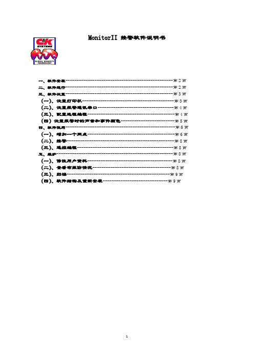
MonitorII 接警软件说明书一、软件安装------------------------------------------------第2页二、软件运行------------------------------------------------第2页三、软件设置------------------------------------------------第3页(一)、设置打印机-----------------------------------------第3页(二)、设置报警通讯串口----------------------------------第4页(三)、配置远程编程---------------------------------------第4页(四)设置报警时的声音和事件颜色------------------------第5页四、软件使用-------------------------------------------------第6页(一)、增加一个网点---------------------------------------第6页(二)、接警------------------------------------------------第8页(三)、遥控编程-------------------------------------------第8页五、维护----------------------------------------------------第8页(一)、修改用户资料--------------------------------------第8页(二)、查看布撤防情况-----------------------------------第8页(三)、归档----------------------------------------------第9页(四)、软件结构及重新安装-----------------------------第9页一、软件安装1、在C盘根目录下建立子目录c:\mon-set,将三张软盘中的文件拷入该目录。

Multimon SennheiserMonitoring SoftwareChat WindowThis can be opened with a button in the detail view, or by pressing the space bar. It will not open if “Attached Devices” is in use.The Send button will send the message typed above to the selected station(s) – the Alert button will do the same, and trigger a flashing alert at the other end. If the Alert button is pressed and the message field is empty, the message “Help!” will be sent.The receipt of a message will open the Chat Window and bring it to the front.The display of the touch-screen keyboard can be toggled with the “Keyboard” button.Controlling Audio Monitoring SystemsWhen a receiver is selected in the main display, if... 1 Monitor IP low byte is not zero.2 There is text in the Monitor Preamble field.3 The Monitor number in this receiver’s detail display is not zero.... a string will be broadcast over UDP to the address ending in the IP low byte value (other bytes are assumed to be the same as the transmitting computer) on port 8141. This string is:Monitor Preamble + Selected Receiver Number (2 digits) + Carriage Return/Line Feed.This string will be re-broadcast every 100ms – the audio monitoring system should acknowledge it by returning a string containing this string (minus the CrLf if required) on port 8138. At this point, the broadcast will cease, and the square around the selected receiver will change from yellow to light blue to indicated that the audio monitoring hardware has responded.Multimon in Operation on Lion King 40Ch Mixed EM 1046 & EM 3732Sennheiser Monitoring SoftwareCat. No. UKMULTIMONQuickstart Guide v 0.7.5Installation – HardwareDrivers for the USB to serial interface should be installed from the included CD. The interface can then be plugged in. The ports can be used interchangeably, but the one used for EM3532s should be set to RS-485 half-duplex, and the one used for EM1046 should be set to RS-422 full duplex. The included interface cables are labelled, and are not interchangeable.Installation – SoftwareThe software can be installed by running the installer and following the prompts.A pre-requisite is version 4.0 of the .NET runtime – the installer is included on the USB key, and is also available here:/en-gb/download/details.aspx?id=17718Main View[Single Click] s elects receiver, triggering telnet communication to any audio routing hardware, and displaying that receiver in the detail view if open. [Double Click] opens Detail view.[Shift + Click] opens Attached Devices view.[Ctrl + Click] w hen Attached Devices panel is open, changes clicked receiver display type to that selected in panel (if there is room in the display to do so). [Drag & Drop] w hen Attached Devices panel is open, moves dragged receiver in display.[Spacebar] o pens chat interface.NOTE EM3732s do not transmit RF values above 300uV.Detail ViewThe long name, short name, and notes fields are freely editable. Clicking on the silhouette allows you to associate a picture with each receiver. The monitor number sets how the receiver is identified to the monitor device.The display below shows a RF/AF history for the currently selected receiver– a receiver does not need to be selected to record history.Attached DevicesThe two drop downs allow COM ports to be selected for communicating with EM3532s and EM1046 LI. The EM1046 port should be configured as an RS-422 port, the EM3532 port as a half-duplex RS-485 port – all other settings are made by the software.The “Port for EM3532” button toggles the attached devices to display their address numbers for checking/changing. The “Port for EM1046” button does nothing.Communication with EM3732s is over LAN – the software will find all devices within the same 255.255.255.0 subnet. This assumption is also made for communication with any audio monitoring hardware, and any slave monitoring stations.When port settings are made, the scan button will attempt to find all attached devices, which will be listed in the box above. They can then be dragged on the display (multi-selection can be used), where the currently selected display type will be used. Placeholder receivers can be added to allow audio monitoring of non-Sennheiser receivers.The “System” button opens the System Dialogue.System DialogueOn start up, the system will load the file “default.xml” in My Documents/Multimon, and save current settings to this file on exit. Settings can also be loaded and saved as to other files using this dialogue.Network state allows the software to be set to master or slave – a master communicates with the receivers directly, and broadcasts this information over UDP to the subnet. If this software is set to slave on another computer on this network, it will discover and monitor these receivers automatically (they will still need to be dragged from Attached Devices on to the main view – some or all of the monitored devices can be viewed).The monitor suffix is set here – the control of monitoring hardware is discussed below.The stations chat name can be set here, as well as the timeout of the chat alert, and whether or not the touch-screen keyboard is shown by default in the chat window.。

转动检测器(即:打滑开关)用户手册说明该手册为用户提供了针对单通道打滑开关的安装、操作和维修等信息。
在系统工作之前,请阅读此手册。
为了人和系统的安全,同时保证产品最好的性能,请您在安装、操作或者维修此机器之前,确认完全理解此手册。
谁将使用该手册?该单通道打滑开关用户手册是一个学习资料,并且对于每个想了解此检测器在皮带运输系统中的安装、操作或者维修的技术人员来讲,是一个很好的参考资源。
手册的组织结构:手册一共设置了八个章节。
第一章:概述。
为用户介绍单通道打滑开关的大体概况和主要特性。
第二章:检查。
为用户提供了对于破损或损坏部件的打开与检查等方面的指导。
第三章:安装。
为用户提供了对该单通道打滑开关的安装的信息。
第四章:操作。
为用户提供了对该单通道打滑开关的操作程序指导。
第五章:理论。
为用户提供了对该单通道打滑开关的操作理论依据。
第六章:故障。
为用户提供了对该单通道打滑开关的故障查找方法。
第七章:更换。
为用户提供了对该单通道打滑开关的部件更换次序信息以及一份部件清单。
第八章:选择。
为用户提供了可选择使用的各种单通道打滑开关型号。
第四章操作运行4.1设计注意事宜警告某些应用可能造成一些问题,并且应该是可以避免的。
例如,当发生一个报警条件时,可以切断设计在一个回路中的60-200-a打滑开关电源。
当电源重新接通时,60-200-1将不会“记得”刚才的报警条件。
它将会像什么都没发生似的,尝试再次启动。
如果要求60-200-1在一个报警信号期间或者由于受到报警时电源扰动的影响而失电,它将“记住”该电气连接的建立,因此没有人员的手动合闸操作,该单元装置将不能重新启动。
考虑到在启动、瞬间的电源扰动、报警、复位或者其他运行条件造成的意外故障时的设计应用。
请注意:启动或者复位可能造成一个瞬间的运行报警,直到电源稳定以后。
4.2安装盒调整当60-200-1打滑开关被连接安装好,它就等待对其进行程序设置。
在其电源侧的备用电池被拆除,进行电源和信号输出的连接后,请确认其备用电池也已经重新安装好。

状态监视器说明书(V1.0)目录1 简介 (3)2 主界面 (3)2.1 主界面显示 (3)2.2 相关按钮功能 (4)3 状态监视器使用 (5)4 打印机状态信息列表 (6)4.1 断电或电缆有问题状态 (6)4.2 打印机未设置双向支持状态 (7)4.3 打印机发生内部故障状态 (7)4.4 打印机暂停状态 (8)4.5 打印机休眠状态 (8)4.6 打印机预热状态 (9)4.7 打印机就绪状态 (10)4.8 打印机处于打印中状态 (10)4.9 打印机发生上盖打开错误 (11)4.10 打印机发生碳粉盒未安装错误 (11)4.11 打印机发生碳粉盒类型不匹配错误 (12)4.12 打印机发生碳粉盒粉量低状态 (13)4.13 打印机发生碳粉盒寿命已尽状态 (14)4.14 打印机发生缺纸状态 (14)4.15 打印机发生出纸处卡纸状态 (15)4.16 打印机发生中间卡纸状态 (16)4.17 打印机发生进纸失败错误 (17)4.18 打印机发生纸型不匹配错误 (18)4.19 打印机发生数据传输错误 (18)4.20 打印机处于作业被取消状态 (19)4.21 打印机处于双面打印中状态 (19)5 其他 (20)1简介该状态监视器通过USB端口,对本地GDI打印机的状态进行监控。
当打印机出现错误或者打印作业出现错误时,该打印机状态监视器程序将自动运行,向用户提供提示信息。
该状态监视器提供的主要功能:1.向用户提供本地打印机的状态。
2.当需要用户干预时候,向用户提供相应的操作提示。
打印机出错时,状态监视器自动弹出;错误排除后,状态监视器自动关闭。
2主界面2.1 主界面显示如上图所示,主要有如下几个区域:z状态提示区:提示当前打印机状态z状态提示区:提示当前打印机状态z动画显示区:以动画的形式提示打印机状态及所需的用户操作。
z作业及碳粉信息状态区:显示当前作业的相关信息。
包括当前页、作业名。


Stereo Triggered Sampler - FirmwaresHow do I know what version I have?Using a computer:Put your microSD card into your computer. Open up the __Sample List__.html file. At the top it will say "Firmware version XXX".Without a computer:1) Go into System Mode (hold both Reverse, both Play, REC and REC Bank buttons down for a few seconds).2) Press and hold the Edit button. Look at the colors of Reverse buttons:Left Reverse = White, Right Reverse = Green ==> 1.5.x (latest version)Left Reverse = White, Right Reverse = Yellow ==> 1.4Left Reverse = White, Right Reverse = Orange ==> 1.3Left Reverse = White, Right Reverse = Red ==> 1.2Left Reverse = Orange, Right Reverse = Orange ==> 1.0 or 1.1 (see note below)3) If the Reverse buttons stay Orange, then you have v1.0 or 1.1. To tell the difference between v1.0 and v1.1, press and hold just the left Reverse button in System Mode. If both Reverse buttons turn White, then you have v1.1. If they remain Orange, you have v1.0.Change log:v1.5.2bReleased: October 14, 2022Download:Firmware v1.5.2bImprovements:Bug Fixes:Start Pos would not go back to 0: With longer sample files, adjusting Start Pos up and then back to 0 would sometimes set the start position such that the first few milliseconds of audio were truncated. Fixed.Clicking when re-triggering a sample with long Fade settings: With longer Fade Up/Down Envelope times, re-triggering an already playing sample would prioritize low latency over the fade-down envelope, causing a click. In v1.5.2b the fade-down envelope is accelerated, adding a little bit of latency when re-triggering but removing the click. Setting the Fade Up/Down envelope time to fast removes the latency and clicking.Looping broken for very short samples when Perc Env is off: When Percussive Envelope was turned off, setting the sample length to be very short could make it not loop. Bug introduced in 1.5.2. Fixed.v1.5.2Released: October 8, 2022Improvements:Smaller firmware update files: The size of the firmware file has been reduced, making the firmware update .wav file smaller by about 57% (from 5:55 to 3:22).Bug Fixes:Long Fade In/Out Envelope times caused clicking in audio under certain circumstances: When the Fade In/Out Envelope Time was set longer than the Trigger Delay Time, firing a play trigger into a channel that's already playing audio would cause the audio to re-start before the fade out had completed, causinga pop or click in the audio. Another circumstance was if the Fade In/Out Envelope Time or PercussiveEnvelope Time was set longer than time between Start Pos and the actual start of sample data, playing a sample in reverse would result in extra silence or glitchy audio. Bug appeared in v1.5, fixed in v1.5.2.Recording Sample Rate not presevered across reboots: The Recording Sample Rate can be set in System Mode up to 96kHz. However, the next time the STS started up, the rate would be set back to44.1kHz, yet the System Mode lights would indicate it was still in 96kHz. One symptom was that sampleswould play back at the wrong pitch. Bug fixed in v1.5.2.v1.5.1bReleased: June 28, 2022New Features:Force Reload SD Card: Hold down four buttons: Bank 1, Bank 2, Rec Bank and Rec, for about 2seconds. Release the buttons when the startup sequence of lights displays.Bug Fix:Unrelated sample file played in certain circumstances: When Start Pos was high, within 0.5s of the end of the file, and Length was just under 50% (Percussive mode) but high enough such that a percussive burst longer than 0.5s was to be played, then the STS would overrun the sample data and play unrelated data (usually a previously played sample). Bug appeared in v1.5, fixed in v1.5.1b.(Note: v1.5.1a was not released)v1.5Released: June 6, 2022Download:Firmware v1.5New Features:Looping Fade Time: The STS can make a longer crossfade between the end and start of a loop(adjustable from 0.36ms to 250ms). This results in a smoother, click-free loop.LED Color Adjustment: You can now adjust the red, green, and blue amounts of each button, letting you match the colors between buttons. All new units ship pre-calibrated.Maximum Recording Rate: You can now record up to 96kHz.Auto Increment Sample Slot on Record: You can enable a mode that moves to the next sample slot each time you finish a recording that was started with the Rec Trigger jack.REC button flashes when you change sample slots: The REC button flashes red or white when you turn the REC Sample knob to indicate if the slot is full or empty.Bug Fix:PLAY button stayed dim red after a recording into an active slot: Fixed. The PLAY button nowindicates the selected sample slot is full immediately after recording into a previously empty slot.STS hangs on boot in some circumstances: Fixed. An issue where the STS could hang on boot while searching for missing sample files is now fixed.v1.4gReleased: August 4, 2020Download:Firmware v1.4gBug Fix:Sequencing Start Pos Glitch Fixed: Using a sequenced CV into Start Pos with gates/triggers into Play Trig would sometimes play the wrong start position if Length was < 50% and triggers were fired fast enough. Fixed.Intermediate versions:(1.4f released June 17, 2020. Improved performance of start-up sequence, and more types of "extended" wav file formats supported)v1.4eReleased: October 20, 2017Download: (not available, please use v1.4g)New Features:Reduced latency by pre-loading each sample file in a bank the first time each sample is played.Latency from trigger until audio output as low as 0.7ms (with Trigger Delay turned to 0, see below)The first time a sample is played after the bank is changed, latency is typically 5ms (may be moredepending on wav file's sampling rate and bit depth). Subsequent times the sample is triggered thelatency is 0.7msVariable "Trigger Delay": Edit + REC Sample knobCompensates for slew/lag when using a CV Sequencer with the Play Trig jack and the either theSample CV or 1V/oct jackThis feature also allows for latency reduction compared to prior firmware versions, which had a built-in delay of about 14msAfter receiving a trigger on the Play jack, the STS will wait the specified delay period before reading the 1V/oct and Sample CV jacks.To use: Press Edit and turn Rec Sample knob. The knob's numbers (1-10) correspond to a delayamount:PCB v1.0a: ranges from 0ms delay (knob at 1) to 14.3ms delay (knob at 10)PCB v1.1: ranges from 0ms delay (knob at 1) to 1.9ms delay (knob at 8), and extra-long delays of 4.1ms (knob at 9) and 8.2ms (knob at 10)Note: If upgrading to v1.4 causes your sequencer and STS to not play well together, set the Trigger Delay to "8" or higherMonitoring on/off per channel: Left and right channels can monitor the inputs separately.Pressing PLAY on one channel while monitoring is on will turn monitoring off for just that channel.Only works in Mono mode.Monitor LED blinks to indicate split monitoring.Typical use would be to patch Right OUT -> Left IN, then Left OUT -> mixer. Then record the right channel's playback.Start-up banks: Can set the default bank to be loaded at start-up.Hold down Edit + Bank 1 + Bank 2 + left PLAY (Save) for 1 second. Current bank selection will be saved as the default after power on.Envelopes can be turned off: Both percussive envelope and longer playback fade in/out envelopeTwo types of envelopes can be turned on or off:Percussive Envelopes: this is the decay-only envelope applied to playback when Length < 50% (actually an attack-only envelope when Reverse is on)Fade In/Out envelope: this is a very short envelope applied to any sample that's played withLength > 50%. It reduces clicks when starting, stopping, or looping playback.In System Mode, left channel Reverse button sets the envelope settings:Orange: Both envelopes enabled (default)Red: Percussive envelope disabledYellow: Fade In/Out envelopes disabledOff: Both envelopes disabledTurning off all envelopes is recommended when playing CV sample files (wav files with clocks/gates, sequencer CV, or slow LFO waveshapes, etc).Turning off Percussive Envelopes is interesting when doing "Granular" patches (see User Manual for example patches)Can toggle Percussive Envelope mode by turning left side Length to 0, and holding left side Reverse for 2 seconds: Reverse button will flash/flickerCan toggle Fade In/Out Envelope mode by turning left side Length to 100%, and holding left side Reverse for 2 seconds: Reverse button will flash/flickerAfter exiting System Mode, right side Length was set to 0, until the knob was moved. Fixed.Intermediate versions: (1.4beta-1 released October 13, 2017) (1.4beta-2 released October 17, 2017: changed Length behavior) (1.4c fixed sticky right length knob when exiting system mode) (1.4d fixed bugs that appeared in v1.4beta2) (1.4e fixed bugs that appeared in v1.3) (1.4f more filtering on 1V/oct jacks, and quantized mode plays better with tracking comp setting)v1.3Released: (beta released Sept 26, 2017)Download:Firmware v1.3 WAV fileNew Features:Drag-and-dropping WAV files to SD card works better:Adding WAV files to an existing folder now adds the files to the bank if there are empty slots.If there are no empty slots, the files can be added using Edit + Next File.On boot, the STS will try to fill empty slots in banks by searching in the bank's folder:If the bank contains files from multiple folders, the lowest-numbered sample file's folder is used.Adjust 1V/OCT jack offsetHold down Bank 1 + Bank 2 + Edit while tapping either REC or REC Bank button.REC shifts downwards, REC Bank shifts upwards.Settings are saved in memory (save using Edit + Save after making necessary adjustments).If there is a difference in pitch between the audio being monitored and playback, or a difference inplayback pitch between channels, then this may need to be adjusted. All units are calibrated in thefactory, but variations in power supplies and grounding configurations of cases may cause DC offsetto appear in a user's system.Fixes:Creating a folder with an exact color name in all lowercase added the folder twice. Fixed.Edit+Next File while in an empty slot now searches in the folder of the first filled slot.Released: (released Sept 8, 2017)Download:Firmware v1.2 WAV fileNew Features:Quantize 1V/oct jack added to System Mode. Each channel can be on/off seperately. Quantization is to semitones (12 notes per octave).In System Mode, tap Bank button for either channel to toggle state.Blue = On (jack is quantized to semitones)Orange = Off (jack is not quantized)Only effects 1V/oct jack, not the Pitch knobSetting is saved in settings file on microSD cardReset tracking compensaion to 1.0000Holding Edit+Rec+RecBankUpdating from v1.0 or v1.1 to v1.2 or later automatically sets tracking to 1.0000 the first time it isloaded (this is necessary because tracking is calculated differently in v1.2 and later)Auto Stop When Sample Changes: "Always keep playing" mode added. There are now three Auto Stop modes. The modes determine what happens when the sample is changed while a sample is being played.Red = Always Stop: The sample instantly stops playing. If looping is on, the new sample startsplaying immediately.Blue = Change When Looping: The sample keeps playing normally -- unless it's looping, in whichcase it stops immediately and the new sample starts.Green = Always Keep Playing: The sample keeps playing normally. If it's looping then the newsample begins when the previous sample reaches the end.Fixes:1V/octave tracking is tighter, +/-0.4 cents over C0-C3Changes:Faster entry into System Mode (2 seconds, instead of 4)Pitch knob's plateau around the center detent is larger, and gradually slopes away from center to make it easier to tune to other sourcesReleased: August 28, 2017Download:Firmware v1.1 WAV fileChanges:On boot, color of lights while index file is loading shows minor version numberIn System Mode, holding down Reverse displays firmware version on Reverse buttons (White, White =1.1)Fixes:Tapping Reverse after changing Channel Volume prematurely updated the Start Pos setting. Fixed.Scrub End setting for samples was not loaded after reboot until Edit button was pushed. Fixed.v1.0Released: August 10, 2017Initial ReleaseFeatures for future firmware versions:Allow for internally patching OUTs to INs for self-recordingSupport AIFF filesWrite index file in background, for faster boot time and "Edit+Save" time。
1-S O L-M A N A G E R(v1.0)-使用说明书-CAL-FENGHAI-(2020YEAR-YICAI)_JINGBIANSOL-MANAGER中盈创信计算机故障维修智能检测平台管理系统V1.0 使用说明书中盈创信(北京)科技有限公司目录一、简介 (4)二、SOL-MANAGER安装卸载说明 (4)2.1 环境准备 (4)2.2 软件安装 (4)2.3 软件激活 (10)2.4 服务器设置 (17)2.5 卸载 (17)三、SOL-MANAGER使用说明 (19)3.1 基础配置 (19)3.1.1 评分模板管理 (19)3.1.2 错误区域显示配置管理 (20)3.1.3 分数分配比例配置管理 (21)3.1.4 检测扣分配置管理 (22)3.1.5 检测平台分配管理 (22)3.2 练习管理 (24)3.2.1 练习项管理 (24)3.2.2 练习管理 (25)3.2.3 练习成绩查询 (28)3.3 考核管理 (29)3.3.1 考核项管理 (29)3.3.2 考核管理 (31)3.3.3 考核成绩查询 (33)3.4 历史查询 (34)3.4.1 历史成绩查询 (34)3.4.2 评测细节查询 (35)3.5 当前状态 (36)3.5.1 查看当前练习 (36)3.5.1 查看当前考核 (36)3.6 器件管理 (37)3.6.1 器件管理 (37)3.6.2 考核项器件标准信息 (38)3.6.3 未审核器件申请表 (41)3.6.4 已审核器件申请表 (47)3.6.5 查询器件分数 (48)一、简介中盈创信芯片级检测与维修实训室专为电子信息类专业建设而设计,实训室设备组件包括芯片级检测与维修功能板、智能检测平台、智能检测平台管理系统和智能检测系统。
计算机故障维修智能检测平台管理系统SOL-MANAGER是整个芯片级检测与维修实训室的核心管理产品,负责对所有智能检测平台及智能检测系统进行统一管理及实验设置。
SOL-MONITOR芯片级检测与维修智能检测平台使用说明书中盈创信(北京)科技有限公司目录简介 (3)SOL-MONITOR硬件接口说明 (3)前面板外观及接口说明 (3)后面板外观及接口说明 (4)SOL-MONITOR基本使用说明 (5)开机 (5)关机 (5)重启动 (6)连接网络 (6)连接功能板 (6)触摸屏使用 (6)SOL-MONITOR内置软件使用说明 (6)练习模式下软件使用说明 (7)开机欢迎界面 (7)测试并选择串口 (7)IP地址设置 (8)测试并连接数据源 (9)远程升级 (11)选择练习电路 (12)新建工作区 (13)进入工作区 (14)维修后检测 (16)错误标记 (17)发送报告 (18)查看报告 (19)考核模式下软件使用说明 (20)开机欢迎界面 (20)测试并选择串口 (21)IP地址设置 (22)测试并连接数据源 (23)远程升级 (24)选择考核电路 (25)新建工作区 (26)进入工作区 (27)维修后检测 (29)错误标记 (30)发送报告 (30)查看报告 (31)简介中盈创信芯片级检测与维修实训室方案专为芯片级检测与维修实训室设计,实训室设备组件包括芯片级检测与维修功能板、智能检测平台、实训室管理软件。
中盈创信智能检测平台SOL-MONITOR,作为每个实验组的核心设备,主要负责与管理服务器SOL-MANAGER联动实现维修前故障智能确认及维修后结果确认,实现课程组织、实验管理、教师及学生管理、成绩管理等功能。
中盈创信芯片级检测与维修实训室方案是各院校组建芯片级检测与维修实训室培养芯片级检测与维修人才的理想选择。
SOL-MONITOR硬件接口说明前面板外观及接口说明1、开机指示灯2、显示屏菜单/确认按钮3、显示屏自动调节/退出按钮4、显示屏左选择按钮5、显示屏右选择按钮6、显示屏开关按钮7、两个USB接口8、40PIN接口(上接口)9、话筒接口10、耳机接口11、40PIN接口(下接口)12、手写笔13、SATA硬盘数据接口14、SATA硬盘供电接口15、开机按钮16、重启按钮17、触摸屏后面板外观及接口说明1、COM接口2、VGA输出接口3、两个USB口4、以太网接口5、220v交流电源接口6、电源开关按钮SOL-MONITOR基本使用说明开机后面板“220v交流电源接口”接电源线并保证正常供电,后面板“电源开关按钮”置于“I”按下状态,按一下前面板的“开机按钮”,智能检测平台将开机启动,进入软件操作界面,进一步进行软件操作。
SOL-MONITOR芯片级检测与维修智能检测平台V1.0使用说明书中盈创信(北京)科技有限公司目录简介 (3)SOL-MONITOR硬件接口说明 (3)前面板外观及接口说明 (3)后面板外观及接口说明 (4)SOL-MONITOR基本使用说明 (5)开机 (5)关机 (5)重启动 (6)连接网络 (6)连接功能板 (6)触摸屏使用 (6)SOL-MONITOR内置软件使用说明 (6)练习模式下软件使用说明 (7)开机欢迎界面 (7)测试并选择串口 (7)IP地址设置 (8)测试并连接数据源 (9)远程升级 (11)选择练习电路 (12)新建工作区 (13)进入工作区 (14)维修后检测 (16)错误标记 (17)发送报告 (18)查看报告 (19)考核模式下软件使用说明 (20)开机欢迎界面 (20)测试并选择串口 (21)IP地址设置 (22)测试并连接数据源 (23)远程升级 (24)选择考核电路 (25)新建工作区 (26)进入工作区 (27)维修后检测 (29)错误标记 (30)发送报告 (30)查看报告 (31)简介中盈创信芯片级检测与维修实训室方案专为芯片级检测与维修实训室设计,实训室设备组件包括芯片级检测与维修功能板、智能检测平台、实训室管理软件。
中盈创信智能检测平台SOL-MONITOR,作为每个实验组的核心设备,主要负责与管理服务器SOL-MANAGER联动实现维修前故障智能确认及维修后结果确认,实现课程组织、实验管理、教师及学生管理、成绩管理等功能。
中盈创信芯片级检测与维修实训室方案是各院校组建芯片级检测与维修实训室培养芯片级检测与维修人才的理想选择。
SOL-MONITOR硬件接口说明前面板外观及接口说明1、开机指示灯2、显示屏菜单/确认按钮3、显示屏自动调节/退出按钮4、显示屏左选择按钮5、显示屏右选择按钮6、显示屏开关按钮7、两个USB接口8、40PIN接口(上接口)9、话筒接口10、耳机接口11、40PIN接口(下接口)12、手写笔13、SATA硬盘数据接口14、SATA硬盘供电接口15、开机按钮16、重启按钮17、触摸屏后面板外观及接口说明1、COM接口2、VGA输出接口3、两个USB口4、以太网接口5、220v交流电源接口6、电源开关按钮SOL-MONITOR基本使用说明开机后面板“220v交流电源接口”接电源线并保证正常供电,后面板“电源开关按钮”置于“I”按下状态,按一下前面板的“开机按钮”,智能检测平台将开机启动,进入软件操作界面,进一步进行软件操作。
关机软关机:在任何时候点击软件窗口右上方便可弹出关机选择窗口,选择关机并确定,检测平台将进行关机操作。
硬关机:按住前面板“开机按钮”10秒钟,检测平台将断电关机。
注意:非特殊情况下不建议进行硬关机。
重启动软重启:在任何时候点击软件窗口右上方便可弹出关机选择窗口,选择关机并确定,检测平台将进行关机操作,机器关闭后再按前面板“开机按钮”启动检测平台。
硬重启:按一下前面板“重启按钮”,检测平台将断电进行重启动操作。
注意:非特殊情况下不建议进行硬重启。
连接网络将双绞线一端RJ-45水晶接口接在后面板“以太网接口”上,另一端接入局域网。
连接功能板在对功能板进行检测前需将检测平台40PIN接口(上接口)与功能板1号外接连线接口(40PIN)通过数据线相连,将检测平台40PIN接口(下接口)与功能板2号外接连线接口(40PIN)通过数据线相连,并将功能板接9V直流电源且将功能板置于开机状态。
功能板使用方法请见相应功能板使用说明。
触摸屏使用在检测平台开机状态下可用手指直接触摸屏幕进行操作,也可使用前面板提供的“手写笔”进行触屏操作。
注意:使用触摸屏时注意触摸力度,以轻柔点击为宜,要避免用力触摸损坏触摸屏。
SOL-MONITOR内置软件使用说明SOL-MONITOR可以与SOL-MANAGER管理系统联动,由管理系统统一管理,自动实现“练习”和“考核”两种模式。
练习模式下软件使用说明开机欢迎界面检测平台启动后将进入开机欢迎界面,点击的叉部分,将进入主操作界面。
测试并选择串口点击主操作界面左上方的按钮,将弹出串口设置界面。
依次选择串口名称,从COM1-COM9,然后点击测试连接,直至显示连接成功信息。
点击“OK”,并点击“保存”,串口信息被保存。
除非检测平台重新启动,否则在使用过程中无需再进行串口设置。
注意:如未进行串口设置并保存,则在后期建立工作区时将提示错误信息:IP地址设置点击主操作界面左上方的按钮,调出软键盘:点击主操作界面左上方的按钮,将弹出IP地址设置界面:通过软键盘输入IP地址、子网关掩码、默认网关的IP地址,点击“设置”,即可设置成功。
设置成功后可关闭软键盘。
注意:IP地址设置只需在检测平台初次安装或网络进行调整后进行设置,平时使用不需要设置。
测试并连接数据源点击主操作界面左上方的按钮,调出软键盘:点击主操作界面左上方的按钮,将弹出数据源配置界面,通过软键盘填入服务器IP,点击测试连接:若连接成功,则显示:然后保存:设置成功后可关闭软键盘。
注意:数据源连接只需在检测平台初次安装或数据源服务器IP进行调整后进行设置,平时使用不需要设置。
远程升级点击主操作界面左上方的按钮,检测平台将与服务器端进行软件版本比对,若有可更新的升级包,则直接下载并升级:升级后检测平台软件将自动重启动。
若服务器上没有更新的软件版本,则不需要升级,将提示:注意:远程升级需在实训室管理系统上加载升级包,需确保实训室管理系统与检测平台的软件版本相匹配,如不匹配,升级后将无法正常使用,建议升级过程在厂家技术人员指导下完成。
选择练习电路根据练习内容及所拿到的功能板进行电路选择。
如练习内容及所拿到的功能板为台式机的CMOS功能板,则首先选择“电路检测导航”栏中的“台式机电路板”,然后在弹出窗口中选择“台式机CMOS&BIOS 电路”,点击“确定”,进入“新建工作区”窗口。
新建工作区在添加工作区前,首先要将功能板准确的连接到检测平台,并将功能板置于开机状态,连接方法见“SOL-MONITOR基本使用说明”-“连接功能板”,功能板开机状态设置方法请见各功能板使用说明书。
如为第一次建立本次练习的工作区,则点击,进入添加个人工作区界面:“工作区名称”部分将由服务器推送,无需学生填写;练习/考核名称、练习/考核项也由服务器端预先定义好,学生只需用下拉菜单选择即可。
如果服务器没有定义好本次练习,则会提示:如果学生接错功能板,则会提示:如果学生接在检测平台上的功能板没有置为开机状态,则需要学生将功能板置为开机状态后再进行新建操作,系统会提示:如果学生设置、连接一切正常,则可建立工作区,保存后新建工作区完毕。
进入工作区对已经建好的工作区可选择,并打开:然后将进入工作区界面,工作区界面将显示本次练习的功能板的相关电路图。
此时请将功能板从检测平台断开,进入学生实际检测维修过程,学生可根据电路图,使用传统检测工具(万用表、示波器等)定位功能板的故障,并使用维修工具(电烙铁、热风焊枪等)对功能板进行维修。
维修后检测待学生主观认为功能板已经维修完好,或想通过检测平台提示哪些区域可能没有维修好,便可进入维修后检测过程,该检测过程可由学生循环使用,直至将功能板全部修好。
首先要将功能板准确的连接到检测平台,并将功能板置于开机状态,连接方法见“SOL-MONITOR基本使用说明”-“连接功能板”,功能板开机状态设置方法请见各功能板使用说明书。
点击“检测”按钮:如检测过程中有任何提示,请按照提示正确操作,如提示:则证明检测时功能板接错或数据线接错。
如提示:则证明检测时功能板未至于开机状态。
如顺利检测完毕,则会提示仍然剩余的可能的故障区域:此时证明电路板上“U5、U2、D5、R16、R12、R11”可能仍存在故障,需要继续维修,待学生再次正确维修后,可能的故障区域会变小:此时证明电路板上“U2、R16、R11”仍可能存在故障,需要继续维修,但前一次的“U5、D5、R12”已经维修好了,待学生完全将功能板上的故障维修好后,将提示:此时已经没有错误区域显示在提示信息中,证明已经完全维修好了。
点击“OK”。
错误标记如果SOL-MANAGER“基础配置”-“错误区域显示配置管理”中对本次考核选择了“显示错误区域”,则在维修后检测完毕后,背景电路图将显示出本块功能板的所有可能的错误区域,学生根据检测与维修过程的汇总,选定错误区域,并标记该区域是否有错误及错误类型,标记后的结果将与维修结果报告一同发送至服务器。
待学生完成维修后检测及错误标记后,便可点击“发送报告”。
点击“发送”,将提示:因每次练习只可发送一次报告,所以确认发送时请特别注意,一旦发送将代表练习完毕,无法继续更改或重新发送报告。
如确认则点“是”,如不确认则点“否”。
查看报告学生在发送完报告后即可查看报告。
点击“检测报告”即可查看报告明细。
考核模式下软件使用说明开机欢迎界面检测平台启动后将进入开机欢迎界面,点击的叉部分,将进入主操作界面。
测试并选择串口点击主操作界面左上方的按钮,将弹出串口设置界面。
依次选择串口名称,从COM1-COM9,然后点击测试连接,直至显示连接成功信息。
点击“OK”,并点击“保存”,串口信息被保存。
除非检测平台重新启动,否则在使用过程中无需再进行串口设置。
注意:如未进行串口设置并保存,则在后期建立工作区时将提示错误信息:IP地址设置点击主操作界面左上方的按钮,调出软键盘:点击主操作界面左上方的按钮,将弹出IP地址设置界面:通过软键盘输入IP地址、子网关掩码、默认网关的IP地址,点击“设置”,即可设置成功。
设置成功后可关闭软键盘。
注意:IP地址设置只需在检测平台初次安装或网络进行调整后进行设置,平时使用不需要设置。
测试并连接数据源点击主操作界面左上方的按钮,调出软键盘:点击主操作界面左上方的按钮,将弹出数据源配置界面,通过软键盘填入服务器IP,点击测试连接:若连接成功,则显示:然后保存:设置成功后可关闭软键盘。
注意:数据源连接只需在检测平台初次安装或数据源服务器IP进行调整后进行设置,平时使用不需要设置。
远程升级点击主操作界面左上方的按钮,检测平台将与服务器端进行软件版本比对,若有可更新的升级包,则直接下载并升级:升级后检测平台软件将自动重启动。
若服务器上没有更新的软件版本,则不需要升级,将提示:注意:远程升级需在实训室管理系统上加载升级包,需确保实训室管理系统与检测平台的软件版本相匹配,如不匹配,升级后将无法正常使用,建议升级过程在厂家技术人员指导下完成。
选择考核电路根据考核内容及所拿到的功能板进行电路选择。
如考核内容及所拿到的功能板为台式机的CMOS功能板,则首先选择“电路检测导航”栏中的“台式机电路板”,然后在弹出窗口中选择“台式机CMOS&BIOS 电路”,点击“确定”,进入“新建工作区”窗口。