RG-S2900系列交换机安装手册
- 格式:pdf
- 大小:503.23 KB
- 文档页数:20

RG-S2900-E系列安全智能千兆交换机产品介绍福建星网锐捷网络有限公司目录1产品图片 (1)2产品概述 (2)3产品特性 (3)4技术参数 (5)5典型应用 (7)6订购信息 (10)1 产品图片图1-1RG-S2928G-E图1-2RG-S2952G-E2 产品概述RG-S2900-E系列交换机包括RG-S2928G-E 、RG-S2952G-E二款产品,是锐捷网络基于网络安全和易用好管理的理念推出的新一代安全智能交换机,充分融合了网络发展需要的高性能、高安全、多业务、易用性特点,为用户提供全新的技术特性和解决方案。
RG-S2900-E系列交换机在提供智能的流分类、完善的服务质量(QoS)和组播应用管理特性同时,并可以根据网络实际使用环境,实施灵活多样的安全控制策略,可有效防止和控制病毒传播和网络攻击,控制非法用户使用网络,保证合法用户合理使用网络资源,充分保障网络安全和网络合理化使用和运营。
RG-S2900-E系列交换机提供了SNMP、Telnet、Web和Console口等多种配置方式方便网络管理和维护,并提供最为灵活和完善的端口组合形式,非常利于用户根据网络布线需要,选择所需的上行链路的接口形式。
RG-S2900-E系列交换机可为各种类型网络接入提完善的端到端的QoS服务质量、灵活丰富的安全策略和基于策略的网络管理,是校园网、企业网、政务网、业务网、宽带小区、商务楼宇等应用的理想接入设备,为用户提供高速、高效、安全、智能的全新接入方案。
3 产品特性全面的安全控制策略●硬件实现端口与MAC地址和用户IP地址的灵活绑定,严格限定端口上的用户接入;●通过将端口设为保护端口即可简单方便地隔离用户之间信息互通,保障了信息安全,同时不必占用VLAN资源;●专用的硬件防范ARP网关和ARP主机欺骗功能,有效遏制了网络中日益泛滥的ARP网关欺骗和ARP主机欺骗的现象,保障了用户的正常上网;●支持DHCP Snooping,可只允许信任端口的DHCP响应,防止未经管理员许可私自架设DHCP Server,扰乱IP地址的分配和管理,影响用户的正常上网;并在DHCP监听的基础上,通过动态监测ARP和检查源IP,可有效防范DHCP动态分配IP环境下的ARP主机欺骗和源IP地址的欺骗;●基于源IP地址控制的Telnet和Web设备访问控制,增强了设备网管的安全性,避免黑客恶意攻击和控制设备;●SSH(Secure Shell)和SNMPv3可以通过在Telnet和SNMP进程中加密管理信息,保证管理设备信息的安全性,防止黑客攻击和控制设备,保护网络免遭干扰和窃听;●通过内在的多种安全机制可有效防止和控制病毒传播和网络流量攻击,控制非法用户使用网络,保证合法用户合理化使用网络,如端口静态和动态的安全绑定、端口隔离、多种类型的硬件ACL控制(如专家级ACL、时间ACL、ACL80等)、基于数据流的带宽限速、用户安全接入控制的多元素绑定等,满足企业网、校园网加强对访问者进行控制、限制非授权用户通信的需求。
Table of ContentsTHIS GUIDE PROVIDES ASSISTANCE WITH THE INSTALLATION OF COMMUNICATION PORTS AND DEVICE DRIVERS FOR GLOBALSTAR SATELLITE PHONES AND EQUIPMENT.Windows XP/2000 2 GSP-1700 for Windows XP/2000 2 GSP-1600/2900 for Windows XP/2000 12Windows Vista 17 GSP-1700 for Windows Vista 17 GSP-1600/2900 for Windows Vista 27Windows XP/2000GSP-1700 for Windows XP/2000Creating a Communications Port for your GSP-1700• Download and launch the program, Installer.exe, on your computerNOTE: IF YOU ARE ENTERING THESE INSTRUCTIONS VIA THE'SATELLITE HELP' BUTTON ON THE QUICK INSTALL PAGE OF THEInstaller PROGRAM, CLICK HERE•Click ‘Next’ to begin your driver install• Accept the software license to continue the install• Click ‘Next’ on the USB adapter screen (not necessary for install of GSP-1700).•Connect your GSP-1700 to your computer.NOTE: If ever you have previously connected your GSP-1700 to your computer and were NOT successful in creating a comm port for it,be sure on this attempt to connect the GSP-1700 to a USB port thatis different from that to which it was connected on your first attempt.If you cannot do so, please contact Globalstar Customer Care at 1-877-452-5782.• Upon connecting your GSP-1700 to your computer, the Windows Add New Hardware Wizard will appear.• Select ‘No, not this time’ and click Next.• Select ‘Install from a list or specific location (Advanced)’ and click Next.• Check the selection, ‘Include this location in the search:' and type c:\wireless.drv\gsp1700in the Browse box. Click the Browse button after typing this location.• Windows will begin searching for instructions it needs to create a communications port for the GSP-1700.•After a period of time it will post a warning regarding Windows Logo certification.Select ‘Continue Anyway’.•Select Finish on the next screen to complete the creation of a communications port for your GSP-1700.•Click on 'Installing Drivers and Dial-Up Networking for your GSP-1700' within this Help file to complete your phone installation.Installing XP/2000 Drivers and DUN for your GSP-1700•If you have not done so yet, create a communications port for yourGSP-1700 on your computer. CLICK HERE for instructions andassistance with creating this comm port.•Verify your GSP-1700 is powered on and connected to yourcomputer. Click ‘Next’.•Select the QUICK INSTALL button.•The installer will begin probing your computer’s communication ports for your GSP-1700. This process may take several minutes. The more communication ports on your computer, the longer the duration of comm port probing. Please be patient.•When the installer finds the GSP-1700 it will ask you to confirm the installation of the modem ‘Globalstar GSP-1700 Modem’. Click OK.•The installer will advise you that the Globalstar GSP-1700 has been successfully installed. Click Next.•Click Finish . You are now ready to use your GSP-1700 for data connections .Using the DUN to Connect to Globalstar DataTo Connect To and Dial your Globalstar Phone:•Click on the Windows Start button and find the Connect To menuselection.•Select the Connect To menu and left click on the Globalstar PacketModem menu item.•Check to see if your Globalstar phone has service.•Click on the Dial button.•Notice the face of your GSP-1700 phone. It should immediatelyregister Connecting…•Once connected, the phone will register as connected and beginlogging seconds of connect time.To Create a Short-cut to your Globalstar Phone Dialer:•Click on the Windows Start button and find the Connect To menu selection.•Select the Connect To menu and RIGHT click on the Globalstar Packet Modem menu item.•Left click on the Create Shortcut item.•Confirm that Yes it is OK to create the shortcut on your computer desktop.GSP-1600/2900 for Windows XP/2000Installing XP/2000 Drivers and DUN for your GSP-1600 • Find and launch the program, Installer.exe, on your computerNOTE: IF YOU ARE ENTERING THESE INSTRUCTIONS VIA THE'SATELLITE HELP' BUTTON ON THE QUICK INSTALL PAGE OF THEDUNSETUP PROGRAM, CLICK HERE•Click ‘Next’ to begin your driver install• Accept the software license to continue the install• Install any USB-serial adapters required to connect your GSP-1600/2900 to your computer. Click on the USB Help button for assistance in doing so. Click Next once the adapters are installed (or if they have been previously installed).• Verify your GSP-1600/2900 phone is powered on and is connected to your computer AND you have successfully installed any necessary USB-serial adapters.If so, select the QUICK INSTALL button.• The installer will begin probing your computer’s communication ports for your GSP-1600/2900. This process may take several minutes. The more communication ports on your computer, the longer the duration of comm port probing. Please be patient.• After a period of time it may post a warning regarding Windows Logo certification.Select ‘ Continue Anyway.'•When the installer finds the GSP-1600/2900 phone it will ask you to confirm the installation. Click OK.•The installer will advise you that the GSP-1600/2900 connection has been successfully installed. Click Next.•Click Finish on the next screen. You are now ready to use your GSP-1600-2900 for data connections .Using the GSP-1600/2900 DUN to Connect to Globalstar Data To Connect To and Dial your Globalstar Phone:• Click on the Windows Start button and find the Connect To menu selection.• Select the Connect To menu and left click on the Globalstar Packet Modem menu item.•Check to see if your Globalstar phone has service.•Click on the Dial button.•Notice the face of your GSP-1600/2900 phone. It shouldimmediately register Connecting…•Once connected, the phone will register as connected and begin logging seconds of connect time.To Create a Short-cut to your Globalstar Phone Dialer:•Click on the Windows Start button and find the Connect To menu selection.•Select the Connect To menu and RIGHT click on the Globalstar Packet Modem menu item.•Left click on the Create Shortcut item.•Confirm that Yes it is OK to create the shortcut on your computer desktop.Windows VistaGSP-1700 for Windows VistaCreating a Communications Port for your GSP-1700 on Vista NOTE: IF YOU ARE ENTERING THESE INSTRUCTIONS VIA THE'SATELLITE HELP' BUTTON ON THE QUICK INSTALL PAGE OF THEInstaller PROGRAM, CLICK HERE•Download and launch the program, Installer.exe, on your computer•Click ‘Next’ to begin your driver install• Accept the software license to continue the install• Click ‘Next’ on the USB adapter screen (not necessary for install of GSP-1700).•Connect your GSP-1700 to your computer•Upon connecting your GSP-1700 to your computer, the Windows Add New Hardware Wizard will appear.NOTE: If ever you have previously connected your GSP-1700 to your computer and were NOT successful in creating a comm port for it,be sure on this attempt to connect the GSP-1700 to a USB port that is different from that to which it was connected on your first attempt. If you cannot do so, please contact Globalstar Customer Care at 1-877-452-5782.•Select ‘Locate and install driver software (recommended)'• Select ‘Continue’ if Windows asks you for permission to proceed with the installation.•Windows will ask you for your Installation CD. If you have the Globalstar Data CD, insert this into your computer now.If you do not have this CD, select ‘I don’t have the disc. Show me other options’.•S elect ‘Browse my computer for driver software (advanced)’.•Type c:\wireless.drv\gsp1700 in the Browse box.Click the Browse button after typing this location.•Windows will begin searching for instructions it needs to create a communications port for the GSP-1700.•After a period of time it will post a warning regarding Windows Logo certification.Select ‘Install this driver software anyway.'•Select Finish on the next screen to complete the creation of a communications port for your GSP-1700.•Click on ' Installing Vista Drivers and DUN for your GSP-1700' within this Help file to complete your phone installation.Installing Vista Drivers and DUN for your GSP-1700 •If you have not done so yet, create a communications port for your GSP-1700 on your computer. CLICK HERE for instructions andassistance with creating this comm port.•Verify your GSP-1700 is powered on and connected to yourcomputer. Click ‘Next’.•Select the QUICK INSTALL button.•The installer will begin probing your computer’s communication ports for your GSP-1700. This process may take several minutes. The more communication ports on your computer, the longer the duration of comm port probing. Please be patient.• After a period of time it may post a warning regarding Windows Logo certification. Select ‘Install this driver software anyway.'•When the installer finds the GSP-1700 it will ask you to confirm the installation of the modem ‘Globalstar GSP-1700 Modem’. Click OK.•The installer will advise you that the Globalstar GSP-1700 has been successfully installed. Click Next.•Click Finish . You are now ready to use your GSP-1700 for data connections.Using the DUN to Connect to Globalstar Data through Vista To Connect To and Dial your Globalstar Phone:•Click on the Windows Start button and find the Connect To menuselection.•Select the Connect To menu and left click on the Globalstar Packet Modem menu item.•Check to see if your Globalstar phone has service.•Click on the Connect button at the base of the screen, then click on the Dial button on the next screen.•Notice the face of your GSP-1700 phone. It should immediatelyregister Connecting…• Once connected, the phone will register as connected and beginlogging seconds of connect time.To Create a Short-cut to your Globalstar Phone Dialer:•Click on the Windows Start button and find the Connect To menuselection.•Select the Connect To menu and RIGHT click on the Globalstar Packet Modem menu item.•Left click on the Create Shortcut item.•Confirm that Yes it is OK to create the shortcut on your computer desktop.GSP-1600/2900 for Windows VistaInstalling Vista Drivers and DUN for your GSP-1600/2900 •Find and launch the program, Installer.exe, on your computerNOTE: IF YOU ARE ENTERING THESE INSTRUCTIONS VIA THE'SATELLITE HELP' BUTTON ON THE QUICK INSTALL PAGE OF THEDUNSETUP PROGRAM, CLICK HERE•Click ‘Next’ to begin your driver install• Accept the software license to continue the install• Install any USB-serial adapters required to connect your GSP-1600/2900 to your computer. Click on the USB Help button for assistance in doing so. Click Next once the adapters are installed (or if they have been previously installed).• Verify your GSP-1600/2900 phone is powered on and is connected to your computer AND you have successfully installed your Vista-compatible USB-serial adapter.If so, select the QUICK INSTALL button.• The installer will begin probing your computer’s communication ports for your GSP-1600/2900. This process may take several minutes. The more communication ports on your computer, the longer the duration of comm port probing. Please be patient.• After a period of time it may post a warning regarding Windows Logo certification.Select ‘ Install this driver software anyway.'•When the installer finds the GSP-1600/2900 phone it will ask you to confirm the installation. Click OK.31•The installer will advise you that the GSP-1600/2900 connection has been successfully installed. Click Next.•Click Finish on the next screen. You are now ready to use your GSP-1600/2900 for data connections .32Using the GSP-1600/2900 DUN to Connect to Globalstar Data through VistaTo Connect To and Dial your Globalstar Phone:•Click on the Windows Start button and find the Connect To menuselection.• Select the Connect To menu and left click on the Globalstar PacketModem menu item.•Check to see if your Globalstar phone has service.•Click on the Connect button at the base of the screen, then click on theDial button on the next screen.•Notice the face of your GSP-1600/2900 phone. It shouldimmediately register Connecting…• Once connected, the phone will register as connected and beginlogging seconds of connect time.To Create a Short-cut to your Globalstar Phone Dialer:•Click on the Windows Start button and find the Connect To menuselection.•Select the Connect To menu and RIGHT click on the Globalstar Packet Modem menu item.•Left click on the Create Shortcut item.•Confirm that Yes it is OK to create the shortcut on your computerdesktop.。
Installation ManualRG-S2300 Series Secure Access SwitchCopyright StatementRuijie Networks Co., Ltd ©2009All rights reserved.Without our written permission, this document may not be excerpted, reproduced, transmitted, or otherwise in all or in part by any party in any means., , ,, , , ,are all registered trademarks of Ruijie Networks Co., Ltd and are protected by law.DisclaimerThe information contained in this manual may be modified without notification. Ruijie Networks has tried its best to maintain the accuracy and reliability of this manual on the website.Ruijie Networks takes no responsibility for the miss, inaccuracy or error and the resulting damage and loss in this manual.ContentsPREFACE (5)1PRODUCT OVERVIEW (7)1.1P RODUCT O VERVIEW (7)1.2M AIN T ECHNICAL C HARACTERISTICS OF RG-S2300 (7)1.3RG-S2300S ERIES S WITCHES (8)1.3.1RG-S2328G Ethernet Switch (8)1.3.2RG-S2352G Ethernet Switch (11)1.4LED I NDICATORS (14)1.5E XTENSION M ODULES (16)1.5.1M2000-02SFP/GT Module (16)1.5.2M3250-STACK Module (17)2PREPARATION BEFORE INSTALLATION (19)2.1S AFETY S UGGESTIONS (19)2.1.1Safety Precautions for Installing the System (19)2.1.2Movement Safety (19)2.1.3Electric Safety (19)2.1.4Static Discharge Damage Prevention (20)2.1.5Laser Safety (20)2.2I NSTALLATION S ITE R EQUIREMENTS (20)2.2.1Ventilation Requirements (20)2.2.2Temperature and Humidity Requirements (20)2.2.3Cleanness Requirements (21)2.2.4EMI (22)2.3S YSTEM G ROUNDING R EQUIREMENTS (22)2.3.1Safety Grounding (23)2.3.2Lightning Grounding (23)2.3.3EMC Grounding (23)2.4L IGHTNING R ESISTANCE C ONSIDERATIONS (23)2.5EMI C ONSIDERATION (24)2.6P RECAUTION FOR F IBER C ONNECTIONS (24)2.7R EQUIREMENTS OF I NSTALLATION T OOLS (24)3PRODUCT INSTALLATION (26)3.1I NSTALLATION P ROCEDURE (26)3.2C ONFIRMATIONS B EFORE I NSTALLATION (26)3.3I NSTALLING THE S2300S ERIES (27)3.3.1Precautions (27)3.3.2Mounting the Switch to a Standard 19-inch Rack (27)3.3.3Mounting the Switch to the Wall (27)3.3.4Mounting the Switch to the Desktop (28)3.4C HECKING A FTER I NSTALLATION (28)4SYSTEM DEBUGGING (29)4.1C ONFIGURATION E NVIRONMENT E STABLISHMENT (29)4.1.1Establishing the Configuration Environment (29)4.1.2Connecting the Console Cable (29)4.1.3Setting Terminal Parameters (29)4.2P OWER-ON S TARTUP (30)4.2.1Checking Before Power-on (30)4.2.2Checking After Power-on (Recommended) (30)5MAINTENANCE AND TROUBLESHOOTING (31)5.1G ENERAL T ROUBLESHOOTING P ROCEDURE (31)5.2T ROUBLESHOOTING C OMMON F AULTS (31)APPENDIX A: CONNECTORS AND CONNECTION MEDIA (33)1000BASE-T/100BASE-TX/10BASE-T P ORTS (33)O PTICAL F IBER C ONNECTION (34)APPENDIX B MINI-GBIC MODULES (35)M ODELS AND T ECHNICAL S PECIFICATIONS OF THE M INI-GBIC(SFP)M ODULE (35)PrefaceThank you for using our switches. This guide (version: V1.02) provides you with detailed operation guide that allows you to easily install and use the switches.ScopeThis manual describes the functional and physical features of the switches, and provides the installation procedures, troubleshooting procedures, technical specifications, and specifications and use rules of cables and connectors. It is intended for the users that have some experience in installing and maintaining network hardware and want to learn the above information. At the same time, it is assumed that the users of this switch are already familiar with the related terms and concepts of Ethernet.Document Structure✧Chapter 1 "Product Overview" describes the main characteristics and typical applications ofthis product.✧Chapter 2 "Preparation before Installation" lists the safety, power supply, and siterequirements that must be met before the switch can be installed.✧Chapter 3 “Product Installation” describes how to install the integrated switch and modulesand connect its power cables and grounding lines.✧Chapter 4 "System Debugging" describes the debugging after the switch is powered on forthe first time.✧Chapter 5 "Maintenance and Troubleshooting” describes how to monitor and maintain theswitch in use.✧Chapter 6 "Troubleshooting" describes possible problems, detections and solutions in thehardware installation and application.✧Appendix A “Connector and Connection Media”✧Appendix B “Mini-GBIC Modules”Related DocumentsSwitch Software Manual——covering CLI commands, software configuration guide, and version release notes.Obtaining DocumentationYou can obtain the documentation you need through the following channels:Internet:You can obtain the latest on-line documentation of Ruijie Networks at:Documentation CD-ROM:The documentation of Ruijie Networks switches is stored in the CD-ROM package, which is provided to you together with the product you purchase. The CD-ROM is updated frequently, and may be more current than the printed documents.Obtaining Technical AssistanceRuijie Networks provides excellent technical support services for all our products. You can obtain the technical assistance you need through any of the following channels:✧ Ruijie Networks website, from which you can obtain the latest product documentation,causes and problems analysis of product faults, application solutions, and software upgrade.✧ Customer service center of Ruijie Networks, which can provide all customers with neededtechnical assistance for: products, technologies and solutions. The customer service center provides responsive technical support for your product installation problems, software configuration problems, and other network performance problems. ✧ Customer services hotline: 4008-111-000✧ Customer services website: ✧ Customer services email: service@Documentation ConventionsThe symbols used in this document are described as below:NoteThis symbol means the supplement or additional information that you may needto know.CautionThis symbol alerts you to the cautions to avoid data loss or switch damage.1 Product Overview1.1Product OverviewThe RG-S2300 series secure access switches are mostly applied at the access layers of small-and-medium-sized networks to provide line-speed exchanging and complete QoS services andensure the undelayed transmission of key data by applying different traffic classification rules todifferent services. The S2300 series provide flexible medium interfaces and can meet theconnection requirements of different media in network constructions.Table 1-1 RG-S2300 seriesModel 10/100Base-Tadaptive Ethernet port 10/100/1000Base-Tadaptive Ethernet port1000Base-X SFP port Console portS2328G 24 2 2 1S2352G 48 2 2 1The 1000Base-X SFP port and a corresponding 10/100/1000Base-T adaptive Ethernet port forma fiber/copper combo port. That is, only one port in the fiber/copper combo port is available at aparticular time.Table 1-2 shows the mappings between two ports that form a fiber/copper comboport.Table 1-2 Mappings between two ports that form a fiber/copper combo portModel 1000Base-X SFP port 10/100/1000Base-T adaptive EthernetportS2328G 25F 25G26F 26GS2352G 49F 49G50F 50G1.2Main Technical Characteristics of RG-S2300Table 1-3 Technical specifications of the S2300 seriesModel S2328GS2352GModule type Mini-GBIC-SX: single-port 1000BASE-SX mini GBIC conversion module (LC port)Mini-GBIC-LX: single-port 1000BASE-LX mini GBIC conversion module (LC port)Mini-GBIC-ZX50: single-port 1000BASE-ZX mini GBIC conversion module (LC interface), 50 kmMini-GBIC-ZX80: single-port 1000BASE-ZX mini GBIC conversion module (LC port), 80 km M2000-02SFP/GT M3250-STACKPower supply AC input:Rated voltage range: 100- 240V AC Maximum voltage range: 90-264V AC Frequency: 50 / 60 Hz Rated current: 0.6 APower consumptionS2328G: with extension modules < 22 W and without extension modules < 18 WS2352G: with extension modules < 31 W and without extension modules < 27 WTemperature Working temperature: 0ºC to 50ºC Storage temperature: -40ºC to 70ºC Humidity Working humidity: 10% to 90% RH Storage humidity: 5% to 90% RH EMC GB9254-1998 and FCC Class A Security complianceGB4943-2001Dimensions (W x D x H) 440 x 300 x 44 mm WeightWith extension modules 3.9 kg and without extension modules 3.5 kg1.3 RG-S2300 Series Switches1.3.1 RG-S2328G Ethernet Switch1.3.1.1 Product AppearanceThe front panel of the RG-S2328G Ethernet switch provides twenty-four 10/100Base-T Ethernet ports, two GE SFP fiber/copper combo ports and one Console port. The backplanel provides the AC power input ports and an extension module slot. Figure 1-1 shows the appearance of the RG-S2328G.Figure 1-1 Appearance of the RG-S2328G1.3.1.2 Ports on the Front PanelFigure 1-2 Schematic diagram of the RG-S2328G front panel - 11. Power system indicator2. Extension module indicator3. Extended port 1 status indicator4. Extended port 2 status indicator5. Console portFigure 1-3Schematic diagram of the RG-S2328G front panel - 26. 10/100Base-T adaptive Ethernet port7. 10/100/1000Base-T adaptive Ethernet port8. 1000Base-X SFP port9. 10/100Base-T adaptive Ethernet port indicator10. 10/100Base-T adaptive Ethernet port indicator11. 1000Base-X SFP port indicator1.3.1.3 Ports on the Back PanelFigure 1-4 Schematic diagram of the RG-S2328G back panel - 11. Extended port2. Label attachmentFigure 1-5 Schematic diagram of the RG-S2328 back panel -23. 3-core AC power interface4. Grounding pole1.3.1.4 Power Supply SystemThe RG-S2328G adopts the AC power input.AC input:Rated voltage range: 100-240V ACMaximum voltage range: 90-264V ACFrequency: 50 / 60 HzRated current: 0.6 A1.3.1.5 Heat Dissipation SystemThe RG-S2328G is designed with no fans. To ensure good dissipation, a ventilation openingspace should be reserved to avoid blocking the air inlet of the cabinet; otherwise, the dissipationmight be affected.1.3.2 RG-S2352G Ethernet Switch1.3.2.1 Product AppearanceThe front panel of the RG-S2352G Ethernet switch provides fourty-eight 10/100Base-T Ethernetports, two GE SFP fiber/copper combo ports and one Console port. The backpanel provides theAC power input ports and an extension module slot. Figure 1-6 shows the appearance of theRG-S2352G.Figure 1-6Appearance of RG-S2352G1.3.2.2 Ports on the Front PanelFigure 1-7 Schematic diagram of the RG-S2352G front panel - 11. Power system indicator2. Extension module indicator3. Extended port 1 status indicator4. Extended port 2 status indicator5. 10/100Base-T adaptive Ethernet port6. Console port7. 10/100Base-T adaptive Ethernet port indicatorFigure 1-8 Schematic diagram of the RG-S2352G front panel - 28. 10/100/1000Base-T adaptive Ethernet port9. 1000Base-X SFP port10. 10/100Base-T adaptive Ethernet port indicator11. 1000Base-X SFP port indicator1.3.2.3 Ports on the Back PanelFigure 1-9 Schematic diagram of the RG-S2352G back panel - 11. Extended portFigure 1-10 Schematic diagram of the RG-S2352G back panel -22. 3-core AC power interface3. Grounding pole1.3.2.4 Power Supply SystemThe RG-S2352G adopts the AC power input. AC input:Rated voltage range: 100-240V AC Maximum voltage range: 90-264V AC Frequency: 50 / 60 Hz Rated current: 0.6 A1.3.2.5 Heat Dissipation SystemThe RG-S2352G is designed with no fans. To ensure good dissipation, a ventilation opening space should be reserved to avoid blocking the air inlet of the cabinet; otherwise, the dissipation might be affected.1.4 LED IndicatorsTable 1-4 LED indicators for the RG-S2328GIndicatorPanel Identification Status MeaningLink indicator StatusOff The switch is not powered on. Solid green The switch is powered on.Extension module indicatorModuleOffThere is no extension module or the extension module is not correctly installed.Solid green The extension module is correctlyinstalled.Extension module port indicator (extended port 1)Link/ACT1OffThe port is down.Solid green The port is up. Flashing greenData are being transceived at the port.Extension module port indicator (extended port 2)Link/ACT2Off The port is down.Solid green The port is up. Flashing green Data are being transceived at the port.10/100Mbps RJ-45 port indicator1 to 24Off The port is down.Solid green The port is up. Flashinggreen Data are being transceived at the port at a rate of 100Mbps. Solid yellow The port is up.Flashing yellowData are being transceived at the port at a rate of 10Mbps. 1000Mbps SFP port indicator25F, 26FOff The port is down.Solid green The port is up.Flashing green Data are being transceived at the port.1000Mbps RJ-45 port indicator25C, 26COffThe port is down.Solid green The port is up.Flashing greenData are being transceived at the port.Table 1-5 LED indicators for the RG-S2352GIndicatorPanel Identification Status MeaningLink indicator StatusOff The switch is not powered on. Solid green The switch is powered on.Extension module indicatorModuleOffThere is no extension module or the extension module is not correctly installed.Solid green The extension module is correctlyinstalled.Extension module port indicator (extended port 1)Link/ACT1OffThe port is down.Solid green The port is up. Flashing green Data are being transceived at the port.Extension module port indicator (extended port 2)Link/ACT2OffThe port is down.Solid green The port is up. Flashing green Data are being transceived at the port.10/100Mbps RJ-45 port indicator1 to 48Off The port is down.Solid green The port is up.Flashing green Data are being transceived at the port at a rate of 100Mbps. Solid yellowThe port is up.Flashing yellowData are being transceived at the port at a rate of 10Mbps. 1000Mbps SFP port indicator49F, 50FOff The port is down.Solid green The port is up.Flashing greenData are being transceived at the port.1000Mbps RJ-45 port indicator49C, 50COff The port is down.Solid green The port is up.Flashing greenData are being transceived at the port.1.5 Extension ModulesThe RG-S2300 series contain the following extension modules: M2000-02SFP/GT and M3250-STACK.1.5.1 M2000-02SFP/GT Module1.5.1.1 Module OverviewFigure 1-12 shows the M2000-02SFP/GT module that is used to extend the two fiber/copper combo ports. Note that the module does not support hot swapping.Figure 1-12 Appearance of the M2000-02SFP/GT module1. 10/100/1000Base-T adaptive Ethernet port2. 10/100Base-T adaptive Ethernet port indicator3. 1000Base-X SFP port indicator4. 1000Base-X SFP port indicator1.5.1.2 Module IndicatorsFigure 1-6 LED indicators for the M2000-02SFP/GTIndicatorPanel Identification Status MeaningPower indicatorPowerOffThe switch is not powered on.Solid greenThe module is already powered on.SFP port indicatorP1/P2OffThe link that connects to the port is not established.Solid green The link that the port connects to is Up. Flashing greenDataarebeingtransceived at the port. CT port indicatorP1/P2OffThe link that connects to the port is not established.Solid green The link that the port connects to is Up. Flashing greenDataarebeingtransceived at the port.1.5.1.3 Technical SpecificationsTable 1-7 Technical specifications of the M2000-02SFP/GT 1.5.2 M3250-STACK Module1.5.2.1 Module OverviewFigure 1-13 shows the M3250-STACK module that is used for the stacking of the S2300 series. The bandwidth of the stack port is 1G.Figure 1-13 Appearance of the M3250-STACK moduleModel M2000-02SFP/GTHot swapping Not supported Power consumption < 4 WTemperature Working temperature: 0ºC to 45ºC Storage temperature: -40ºC to 70ºC Humidity Working humidity: 10% to 90% RH Storage humidity: 5% to 90% RH Weight Net weight about 0.4 kg Dimensions100 x 110 (mm)1. Stack module power indicator2. Stack port3. Stack port indicator1.5.2.2 Module IndicatorsFigure 1-8M3250-STACK IndicatorsIndicator Panel Identification Status Meaning Power indicator Power Off The switch is notpowered on.Solid green The module is alreadypowered on.Stack port indicator STACK-P1/P2 Off The link that connectsto the stack port is notestablished.Solid green The link that connectsto the stack port is Up.Flashing green Data are beingtransceived at thestack port.1.5.2.3 Technical SpecificationsTable 1-9 Technical specifications of the M3250-STACKModel M3250-STACKHot swapping Not supportedTemperature Working temperature: 0ºC to 45ºCStorage temperature: -40ºC to 70ºCHumidity Working humidity: 10% to 90% RHStorage humidity: 5% to 90% RHWeight Net weight about 0.2 kgDimensions 100 x 110 (mm)2 Preparation Before Installation2.1Safety SuggestionsTo avoid personal injury and equipment damage, please carefully read the safety suggestionsbefore you install the RG-S2300 series.The following safety suggestions do not cover all possible dangers.Note2.1.1 Safety Precautions for Installing the System✧Keep the chassis clean, free from any dust.✧Do not place the switch in a walking area.✧Do not wear loose clothes or any other things that may be caught by the chassis duringinstallation and maintenance.✧Turn off all power supplies and remove the power sockets and cables before dismantlingthe cabinet.2.1.2 Movement Safety✧Do not frequently move the switch.✧When moving the switch, note the balance and avoid hurting legs and feet or straining theback.✧Before moving the switch, turn off all power supplies and dismantle all power modules.2.1.3 Electric Safety✧Observe local regulations and specifications when performing electric operations. Relevantoperators must be qualified.✧Carefully check any potential danger in the working area, such as ungrounded powersupply, unreliable grounding of the power supply, and damp/wet ground or floor.✧Find out the location of the emergency power supply switch in the room before installation.First cut off the power supply in the case of an accident.✧Try to avoid maintaining the switch that is powered-on alone.✧Be sure to make a careful check before you shut down the power supply.✧Do not place the equipment in a damp location. Do not let any liquid enter the chassis.Caution 1. Any nonstandard and inaccurate electric operation may cause an accident such as fire or electrical shock, thus causing severe even fatal damages to human bodies and the switch.2. Direct or indirect touch through a wet object on high-voltage and mains supply can bring a fatal danger.2.1.4 Static Discharge Damage PreventionTo prevent damage from static electricity, pay attention to the following:(1) Proper grounding of the switch and floor(2) Indoor dust prevention(3) Proper humidity conditions2.1.5 Laser SafetyAmong the modules supported by the RG-S2300 series, a great number of optical modules are Class I laser products. Therefore, pay attention to the following when you use them:✧When a fiber transceiver works, ensure that the port has been connected with an opticalfiber or is covered with a dust cap, to keep out dust and avoid burning your eyes.✧Do not stare into any optical port.Caution Do not stare into any optical port under any circumstances, as this may cause permanent damage to your eyes.2.2Installation Site RequirementsThe RG-S2300 series must be used indoors. To ensure the normal working and a prolongeddurable life of the switch, the installation site must meet the following requirements.2.2.1 Ventilation RequirementsFor the RG-S2300 series, you must ensure that sufficient space is reserved at the ventilationopenings to ensure the normal ventilation. After various cables have been connected, theyshould be arranged into bundles or placed on the cabling rack, to avoid blocking the air inlets.2.2.2 Temperature and Humidity RequirementsTo ensure the normal operation and prolong the service life of RG-S2300 series, you shouldkeep proper temperature and humidity in the equipment room.If the equipment room has temperature and humidity that do not meet the requirements for along time, the switch may be damaged.✧ In an environment with high relative humidity, the insulating material may have badinsulation or even leak electricity. Sometimes the materials may suffer from mechanicalperformance change and metallic parts may get rusted.✧ In an environment with low relative humidity, however, the insulating strip may dry andshrink. Static electricity may occur easily and endanger the circuit on the switch.✧ In an environment with high temperature, the equipment is subjected to even greater harm,as its performance may degrade significantly and its useful life may be shortened in thecase of long-term exposure that expedites the aging process.Therefore, the ambient temperature and humidity of the RG-S2300 series must meet the requirements listed in 0:Table 2-1 Temperature and humidity requirements of the RG-S2300 series TemperatureRelative Humidity Long-termcondition Short-term condition Long-term condition Short-term condition15ºC-40ºC 0ºC-45ºC 40%-65% 10%-90%Note 1. The ambient temperature and humidity are measured at the point that is 1.5 mabove the floor and 0.4 m before the switch when there is no protective plate infront or back of the switch rack.2. The short-term working condition applies where the continuous working perioddoes not exceed 48 hours and the accumulative total period within a year doesnot exceed 15 days.2.2.3 Cleanness RequirementsDust poses the top threat to the switch running. The indoor dust falling on the switch may beadhered by the static electricity, causing bad contact of the metallic joint. Such electrostatic adherence may occur more easily when the relative humidity is low, not only affecting the switch service life, but also causing communication faults. 错误!未找到引用源。

RG-ES08 / RG-ES08GSeries Switch Quick Installation Guide 系列交换机快速安装指南锐捷以太网交换机快速安装指南Ruijie Ethernet Switches Installation Quick Start本指南适用于RG-ES08和RG-ES08G,执行标准:GB 4943.1-2011 GB/T 9254-2008。
This quick start applies to RG-ES08 and RG-ES08G, the execution standards include GB 4943.1-2011 and GB/T 9254-2008.1 设备安装Install the Device安装到墙壁Wall Mounting第一步:根据交换机底部的槽位,在墙上定位并钻孔,两边各自拧入一颗M3螺丝(自备)。
留出螺丝头用于挂壁。
Step1: Drill two holes in the wall based on the distance between the two slots on the bottom panel of the switch. Put and tighten two M3 screws (self-prepare) into the holes, and keep an appropriate distance between the inner edge of the screw head and the wall to ensure that the switch can be hung on the screws firmly.第二步:将交换机底部的槽对准螺丝头,滑入并扣紧。
Step 2: Align the slots of the switch to the screw heads, and slip the switch to make it fixed on the screws firmly.安装到桌面Desktop Mounting将交换机正面朝上置于足够大且平稳的桌面上即可。
硬件安装手册RG-S2900系列交换机文档版本号:V1.24版权声明锐捷网络©2014锐捷网络版权所有,并保留对本手册及本声明的一切权利。
未得到锐捷网络的书面许可,任何人不得以任何方式或形式对本手册内的任何部分进行复制、摘录、备份、修改、传播、翻译成其他语言、将其全部或部分用于商业用途。
、、、、、、、、、、、都是锐捷网络的注册商标,不得仿冒。
免责声明本手册内容依据现有信息制作,由于产品版本升级或其他原因,其内容有可能变更。
锐捷网络保留在没有任何通知或者提示的情况下对手册内容进行修改的权利。
本手册仅作为使用指导,锐捷网络在编写本手册时已尽力保证其内容准确可靠,但并不确保手册内容完全没有错误或遗漏,本手册中的所有信息也不构成任何明示或暗示的担保。
技术支持4008-111-000前言感谢您使用锐捷网络产品,本手册为您提供了详细的硬件安装指南。
使用范围本手册主要介绍了产品在功能上和物理上的一些特性,提供了安装步骤、故障排除、技术规格,以及电缆和连接器的规格和使用准则。
适用于想对上述内容进行了解且在安装和维护网络硬件方面具有一定经验的用户。
同时假定该款产品的用户熟知相关术语和概念。
技术支持⏹锐捷网络官方网站:/⏹锐捷网络在线客服:⏹锐捷网络远程技术支持中心:/service.aspx⏹7×24小时技术服务热线:4008-111-000⏹锐捷网络技术论坛:⏹锐捷网络技术支持与反馈信箱:******************.cn相关资料手册名称说明产品配置手册本手册对产品支持的各网络协议及其实现原理进行了描述,并配有详细的配置实例。
产品命令手册本手册对产品支持的配置命令做了详细的描述。
包括命令模式、参数说明和使用指南等,并配有具体的实例。
产品WEB管理手册本手册对产品支持的各功能的WEB 界面进行描述,并配有详细的配置实例。
文档格式约定本书采用各种醒目标志来表示在操作过程中应该特别注意的地方,这些标志的意义如下:注意、警告、提醒操作中应注意的事项。
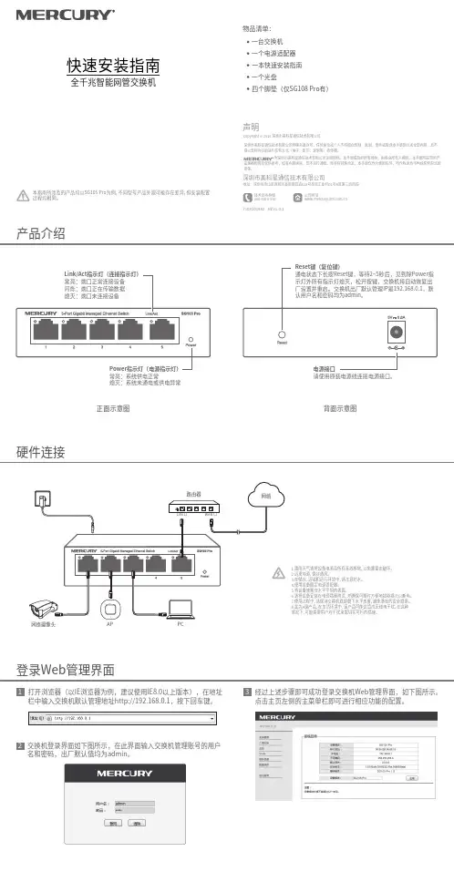
物品清单:一台交换机一个电源适配器一个光盘一本快速安装指南产品介绍快速安装指南全千兆智能网管交换机硬件连接背面示意图正面示意图Copyright © 2018 深圳市美科星通信技术有限公司声明深圳市美科星通信技术有限公司明确书面许可,任何单位或个人不得擅自仿制、复制、誊抄或转译本手册部分或全部内容,且不 为深圳市美科星通信技术有限公司注册商标。
本手册提及的所有商标,由各自所有人拥有。
本手册所提到的产品规格和资讯仅供参考,如有内容更新,恕不另行通知。
除非有特殊约定,本手册仅作为使用指导,所作陈述均不构成任何形式的担保。
技术支持热线400-8810-500公司网址深圳市美科星通信技术有限公司地址:深圳市南山区高新区高新南四道023号高新工业村R1号B区第三层西段7108501982 REV1.0.1本指南所涉及的产品均以SG105 Pro为例,不同型号产品外观可能存在差异,但安装配置过程均相同。
2四个脚垫(仅SG108 Pro有)熄灭:系统未通电或供电异常1.雷雨天气请将设备电源及所有连线拆除,以免遭雷击破坏。
2.远离热源,保持通风。
3.在储存、运输和运行环境中,请注意防水。
4.使用设备额定电源适配器。
5.将设备放置在水平平坦的表面。
6.请将设备安装在电源插座附近,并确保可随时方便地拔掉插头以断电。
7.使用过程中,请保持交换机底部朝下水平放置,避免潜在的安全隐患。
8.此为A级产品,在生活环境中,该产品可能会造成无线电干扰。
在这种情况下,可能需要用户对干扰采取切实可行的措施。
登录Web管理界面1打开浏览器(以IE浏览器为例,建议使用IE8.0以上版本),在地址栏中输入交换机默认管理地址http://192.168.0.1,按下回车键。
交换机登录界面如下图所示,在此界面输入交换机管理账号的用户名和密码,出厂默认值均为admin。
3经过上述步骤即可成功登录交换机Web管理界面,如下图所示。
点击主页左侧的主菜单栏即可进行相应功能的配置。

2950交换机简明配置维护手册中望商业机器公司2002-12-14目录说明 (3)产品特性 (3)配置端口 (4)配置一组端口 (4)配置二层端口 (6)配置端口速率及双工模式 (6)端口描述 (7)监控及维护端口 (8)监控端口和控制器的状态 (8)刷新、重置端口及计数器 (10)关闭和打开端口 (10)配置VLAN (11)理解VLAN (11)可支持的VLAN (12)配置正常范围的VLAN (12)生成、修改以太网VLAN (13)删除VLAN (14)将端口分配给一个VLAN (15)配置VLAN Trunks (16)使用STP实现负载均衡 (19)配置Cluster (24)说明本手册只包括日常使用的有关命令及特性,其它未涉及的命令及特性请参考英文的详细配置手册。
产品特性2950是只支持二层的交换机支持VLAN∙到250 个VLAN∙支持VLAN ID从1到4094(IEEE 802.1Q 标准)∙支持ISL及IEEE 802.1Q封装安全∙支持IOS标准的密码保护∙支持标准及扩展的访问列表来定义安全策略∙支持基于VLAN的访问列表监视∙交换机LED指示端口状态∙SPAN及远端SPAN (RSPAN) 可以监视任何端口或VLAN的流量∙内置支持四组的RMON监控功能(历史、统计、告警及事件)配置端口配置一组端口当使用interface range命令时有如下的规则:∙有效的组范围:o vlan从1 到4094o fastethernet槽位/{first port} - {last port}, 槽位为0o gigabitethernet槽位/{first port} - {last port},槽位为0o port-channel port-channel-number - port-channel-number, port-channel号从1到64∙端口号之间需要加入空格,如:interface range fastethernet 0/1 – 5是有效的,而interface range fastethernet 0/1-5是无效的.∙interface range命令只能配置已经存在的interface vlan∙所有在同一组的端口必须是相同类别的。
用于思科 2900 和 3900 系列路由器的思科增强型 EtherSwitch 服务模块思科®增强型 EtherSwitch®服务模块可以将千兆以太网 (GE) 和快速以太网 (FE) 交换机端口,集成到思科 3900 和 2900 系列集成多业务路由器中,从而帮助您的企业降低总体拥有成本。
这种集成使网络管理员能够使用思科管理工具,或用用于局域网和广域网管理的路由器命令 (CLI) 来管理单一设备。
这种方式可以降低网络复杂性、降低维护成本、缓解员工培训需求、简化软件资格认证工作、提高可用性,以及为分支机构和总部提供一致的应用体验。
产品概述通过集成行业领先的第二层和第三层交换,获得思科 Catalyst® 3560- E 和 Catalyst 2960 系列交换机的同等特性,思科增强型 EtherSwitch 服务模块(图 1)可以极大地扩展路由器的功能。
全新的思科增强型 EtherSwitch 服务模块率先利用了思科 3900 和 2900 系列集成多业务路由器中的新增功能。
此外,这些服务模块还支持思科的行业领先的电能管理计划,即思科 EnergyWise®、思科增强型以太网供电(ePoE)和端口 PoE 电能监控。
所有这些使分支机构可通过扩展更加轻松地满足下一代网络需求,同时通过重要计划确保 IT 团队在高能效的网络中工作。
思科增强型 EtherSwitch 服务模块不仅执行本地线路速率交换和路由,还能通过第二代集成多业务路由器多千兆矩阵(Multigigabit Fabric,MGF)分离局域网和广域网资源,从而支持“网络模块到服务模块”的直接通信。
图 1. 思科增强型 EtherSwitch 服务模块思科增强型 EtherSwitch 服务模块类型思科增强型 EtherSwitch 服务模块提供了两种类型(表 1):入门级 (ES2) 和高级 (ES3)。
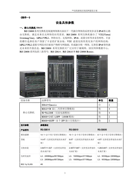
《附件一》设备具体参数一、核心交换机S8610RG-S8600系列交换机是锐捷网络推出面向下一代融合网络的高密度多业务IPv6核心路由交换机,满足未来以太网络的应用需求。
RG-S8600系列交换机融合了VSU(Virtual Switching Unit)、MPLS/VPLS、网络安全、无线网络、IPv6、流量分析等多业务特性。
丰富的槽位选择给客户预留了丰富的扩展余地,VSU虚拟化特性简化客户的网络结构,MPLS/VPLS虚拟专网技术打破客户物理专网隔阂,形成融合统一网络,完善的IPv6特性满足未来的升级改造。
RG-S8600系列交换机可广泛应用于城域网、园区网和数据中心。
RG-S8600系列包括三款型号:RG-S8614、RG-S8610和RG-S8606-Bseries。
1、主机箱及管理引擎根据产品具体型号选择需配置的主机箱及管理引擎。
2、电源配置可以选择交流电源,也可以选择直流电源,二者必配其一。
3、主机线卡根据具体情况选择主机线卡。
二、汇聚交换机RG-S5750系列RG-S5750系列是锐捷网络推出的硬件支持IPv6的万兆多层交换机。
该系列交换机提供的接口形式和组合非常灵活,即可以提供24个或48个10/100/1000M自适应的千兆电口(不包含扩展模块端口),又可以提供有24个SFP千兆光口(不包含扩展模块端口),又能提供PoE远程供电的接口,满足网络建设中不同传输介质的连接需要。
RG-S5750系列交换机以极高的性价比为大型网络汇聚、中型网络核心、数据中心服务器接入提供了高性能、完善的端到端的服务质量、灵活丰富的安全设置和基于策略的网管,最大化满足高速、安全、智能三、接入交换机RG-S2952G-ERG-S2900系列交换机是锐捷网络基于安全、易用、好管理的理念推出的新一代全千兆安全智能弱三层交换机,采用了锐捷新一代支持多平台的模块化操作系统RGOS,为用户完整的提供了智能、安全、高速、简单管理的千兆到桌面解决方案。


发行说明RG-S2900系列交换机RGOS 10.2(5), Release (66183) 正式版本版权声明福建星网锐捷网络有限公司©2009版权所有,保留一切权利。
没有经过本公司书面许可,任何单位和个人不得擅自摘抄、复制本书内容的部分或者全部,并且不得以任何形式传播。
、、、、、、、都是福建星网锐捷网络有限公司的注册商标,不得仿冒。
前言本文记录了RG-S2900系列交换机RGOS 10.2(5), Release(66183)版本的信息,内容包括:关于本文的任何疑问,请咨询锐捷网络技术支持热线:4008-111-000 。
目录1基本信息 (5)2硬件特性 (5)2.1支持的硬件 (5)2.2硬件限制 (6)3软件特性 (6)3.1解决问题 (6)3.2新增功能 (8)3.3功能变更 (9)3.4软件限制 (9)4配套手册 (10)5升级说明 (11)5.1升级文件清单 (11)5.2升级注意事项 (11)1 基本信息2 硬件特性2.1 支持的硬件2.2 硬件限制无3 软件特性3.1 解决问题该版本解决了以下问题:3.2 新增功能在基线版本的基础上新增以下功能:3.3 功能变更无。
3.4 软件限制本版本中已知的问题以及对应的规避措施其他限制这里主要说明第2代su下发功能的限制:SU分发功能,将认证用户从MAC地址表切换为FP表来实现。
由于FP表是许多安全功能共用的资源,所以安全功能的使用情况对容量指标会有较大影响。
并且会引入许多的限制。
在部署SU分发功能的时候,请特别注意。
4 配套手册该版本适用的产品用户手册如下:以上产品用户手册可从锐捷网络技术支持网站下载:/。
5 升级说明5.1 升级文件清单5.2 升级注意事项在对该版本进行升级的过程中,请注意以下事项:1、从V10.0版本升级时,主程序必须先升级到10.1(4)后,再升级到10.2(2)。
2、在升级或者自动升级过程中,会有不允许重启的提示,一旦出现类似提示,请务必不要断电或者复位系统,也不要随便插拔其他模块。
电话交换机接线图及安装接线示意图2009-06-24 16:37:13| 分类:默认分类| 标签:|字号大中小订阅目前,国内程控交换机用户接口输出采用三种接口,一是分机板端口采用RJ11(小型)电话口,二是采用25针插座,2002年以前老式接口均采用,(像打印机插座一样);三是现在最流行的是用RJ45网络接口方式。
一、小型电话交换机采用RJ11水晶头,这种最为简单,标明了RJ11分机及外线端口,国内如佛山产的电话交换机、广东产的程控交换机及TCL王牌都采用此接口,RJ11水晶头只要中间两芯。
(略)二、程控电话交换机采用25针插座输出,接法详见如示意图。
(国产电话交换机用电脑25针各厂家接法相同<如上海产的,温州产的等)此机型安装接线说明:9针插座为中继板(TRK)端口,25针插座为用户分机板(EXT)端口;每个9针插座可以接入4条中继线,每个25针插座可以接出8门分机线;用户分机板(EXT)端口排序是在“交换机背面”数,从“右”往“左”数第一块是第1号用户分机板(总机在此板的第一对线为8000总机)。
从“右”往“左”数第二块是第2号用户分机板,依次类推。
三、程控电话交换机采用RJ45网络接口输出,为最新电话交换机接口方式,接法详见如示意图图。
(凡是国内电话交换机用RJ45各厂家接法相同)此机型安装接线说明:每个RJ45插座可以接入4门分机线;一块用户板有两个RJ 45插座共8门分机线;用户中继板(标有TRK)端口;用户分机板(标有EXT)端口排序是在“交换机背面”数,标有EXT从“右”往“左”数第一块是上面为第1号用户分机端口(总机在此板的第一对线为8000总机),下面为第2号用户分机端口。
从“右”往“左”数第二块是第2号用户分机板,上面为第3号用户分机端口,下面为第4号用户分机端口,依次类推。
各种集团电话交换机接线示意图-程控电话交换机接线图电话交换机与电缆分线盒接法图电话交换机输出线接到分线盒背面,分线盒正面接用户安装的电话线或网线或通信电缆到各部门或办公室,如图例.电话交换机与配线箱接法接法图1、配线箱模块不做回线接法。
锐捷网络公司及产品介绍(1)2010年12月29日星期三下午 03:51前段时间为某人整理的锐捷的资料,共享之。
锐捷网络介绍公司简介:锐捷网络是业界领先的网络设备及解决方案供应商,成立于2000年1月。
十年来,秉承“敏锐把握应用趋势,快捷满足客户需求”的核心经营理念,坚持“应用领先”的发展道路,锐捷网络实现了超常规、跨越式发展,成长为网络设备民族第一品牌,跻身中国网络市场三大供应商之列。
今天的锐捷网络,已经在全国设立了37个分支机构,并成功布局海外市场,是一家拥有包括交换、路由、软件、安全、无线、存储等全系列的网络产品线及解决方案的专业化网络厂商。
其产品和解决方案被广泛应用于政府、教育、金融、医疗、企业、运营商等信息化建设领域,并远销东南亚、欧洲、南北美洲、中东等地区,2009年销售额13.5亿元。
2010年月,其母公司福建星网锐捷通讯股份有限公司正式在深交所A股市场上市,将为公司的进一步发展打下良好基础。
公司规模:目前,锐捷网络拥有员工2000余名,技术人员占总人数的60%。
使命:推动网络技术发展,引领网络应用浪潮;让技术与应用充分融合,促进社会进步。
核心价值观:以人为本,以客户为中心,坚持诚信,渴望变革,注重业绩。
产品:(主要了解路由器交换机系列,后面没有注释的锐捷官方网站上找不到,了解型号就行)l 交换机系列:核心路由交换机:RG-S9600系列RG-S9600是锐捷网络推出的面向十万兆平台设计的下一代超高密度多业务IPv6核心路由交换机,满足未来以太网络和城域网的应用需求,支持下一代的以太网100G速率接口,提供20竖插槽设计和10竖插槽设计两种主机:RG-S9620和RG-S9610。
RG-S9600系列超高密度多业务IPv6核心路由交换机提供9.6T/4.8T背板带宽,并支持将来更高带宽的扩展能力,高达3571Mpps/1786Mpps的二/三层包转发速率可为用户提供高密度端口的高速无阻塞数据交换。
修订记录1 产品综述1.1 产品简介RG-RAP120是锐捷网络专门为酒店、办公室和宿舍楼房无线网络推出的新一代基于802.11ac协议的迷你型胖瘦一体化的墙面式无线接入点(WallAP)。
采用双路双频设计,5GHz射频单元可以提供高达866.5Mbsp的接入速率,2.4GHz射频单元可以提供300Mbsp的接入速率,单个AP可以提供1166.5Mbps的接入速率。
RG-RAP120 尺寸按照标准86面板盒规格设计,可方便地在86mm面板盒上进行安装,而且还集成了以太网口和IP电话接口,整机设计简洁美观、部署便捷,可以在不破坏墙面装修的情况下安装在接线盒上,是酒店、宿舍等环境无线网络建设的最佳选择。
1.2 无线接入点详细介绍1.2.1 RG-RAP120无线接入点1.2.1.1 RG-RAP120产品主要技术指标1.2.1.2 RG-RAP120产品外观RG-RAP120包含2个无线射频口(内置)、1个千兆以太网WAN口,4个百兆以太网LAN口。
其外观如下图所示:图1-1 RG-RAP120产品外观图蓝色端口为PoE/UpLNK口,为1000/100/10BASE-T自适应以太网上联口(WAN),支持PoE供电。
黄色端口为PassThrough口,与侧面的PassThrough口为直通连接。
图1-2 RG-RAP120产品侧面板外观图在图1-2中:①复位暗孔②防盗锁条插孔③MicroUSB管理接口(Console)④防盗钥匙孔⑤PassThrough侧面口图1-3 RG-RAP120产品上盖指示灯示意图在图1-3中RG-RAP120设备指示灯的功能说明如下表:1.2.1.3 RG-RAP120电源系统RG-RAP120 的电源采用PoE输入,供电时需要确保以太网另一端具有802.3af供电能力。
⏹输入电压范围:44-57V⏹额定电流:0.25APOE供电时可与我司具有802.3af PoE功能产品相配套使用.1.2.1.4 RG-RAP120散热系统RG-RAP120采用无风扇散热设计。