Accuri C6软件介绍
- 格式:pdf
- 大小:2.29 MB
- 文档页数:22
7. 使用虚拟增益TM功能调节峰的位置在有些情况下,需要不同样本的某个特定的峰始终在相同的位置,或者出现在坐标轴相同的荧光道数位置——无论不同样本之间染色条件是否均一。
使用调节电压和可变增益方式的流式细胞仪可以调节不同样本的峰的位置。
BD Accuri C6使用虚拟增益功能来实现这样的调节。
虚拟增益是一个模拟调节电压和可变增益的软件模块,可以实现对已获取的数据在坐标轴上位置的重新调节。
虚拟增益可以实现对直方图的整体调节(峰位置的移动)。
虚拟增益是个严格意义的分析工具,不可以在收集数据时使用。
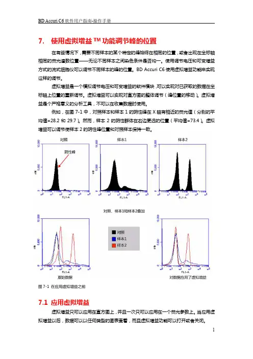
例如,在图7-1中,对照样本和样本1的阴性峰在X轴有相近的荧光值(分别的平均值=28.2和29.7)。
然而,样本2的阴性群体在右边更远的位置(平均值=73.4)。
虚拟增益可以调节使样本2的阴性峰位置和对照样本保持一致。
图7-1 在应用虚拟增益之前7.1 应用虚拟增益虚拟增益只可以应用在直方图上,并且一次只可以应用在一个荧光参数上。
当应用虚拟增益以后,数据可以以任何类型的图表查看,而且虚拟增益功能可以打开或者关闭。
虚拟增益只能被应用在正在显示的数据上,并不改变FCS数据本身。
所做的调节只在BD Accuri C6文件中被记录。
这样应用虚拟增益:∙在分析页面,做下列操作之一:- 重新生成要应用虚拟增益的直方图(看4.2.3章节的细节描述)。
- 从收集页面拷贝图表(看4.2.1章节的细节描述)图7-2 设置应用虚拟增益的直方图在分析页面,对图表应用合适的门。
∙做下列操作之一:- 选择当前样本的一张直方图,其他样本将参照它进行调节,这个样本是标准样本。
- 选择一个空的孔,将峰调节到特定的荧光通道值,不要选已收集数据的孔。
∙点击标准样本的x轴标记,从下拉菜单中选择虚拟增益。
∙在虚拟增益对话框中,做下列操作之一- 在标准样本的图表中,移动峰的定义标记的位置(竖直线)到峰的中央,这将是参考位置,其他样本的峰会被调节到此位置。
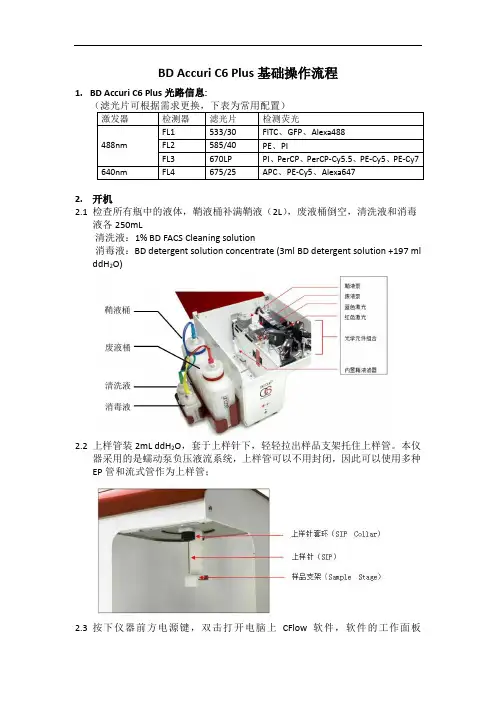
BD Accuri C6 Plus基础操作流程1.BD Accuri C6 Plus光路信息:2.开机2.1 检查所有瓶中的液体,鞘液桶补满鞘液(2L),废液桶倒空,清洗液和消毒液各250mL清洗液:1% BD FACS Cleaning solution消毒液:BD detergent solution concentrate (3ml BD detergent solution +197 ml ddH2O)2.2上样管装2mL ddH2O,套于上样针下,轻轻拉出样品支架托住上样管。
本仪器采用的是蠕动泵负压液流系统,上样管可以不用封闭,因此可以使用多种EP管和流式管作为上样管;2.3按下仪器前方电源键,双击打开电脑上CFlow软件,软件的工作面板(workspace)分布如下图,或者在File下点击New Workspace打开新的workspace:2.4仪器启动期间,软件界面上仪器当前状态会显示黄色的灯,该过程中仪器会用鞘液冲洗液流管路,持续大约13分钟,直到显示绿灯;2.5当仪器状态显示绿灯时,表示仪器和软件连接完成。
3.质控3.1 点击面板上的”Instrument QC”,进入质控界面;3.2500ul ddH2O + 1滴BD CS&T RUO Bead(#661414、661415),混匀3.3BD CS&T Bead Lot选择CS&T小球的批号(注意不是货号),如没有则在Install下倒入对应的批号文件;3.4点击RUN开始获取数据;3.5结束后取下质控小球,放上一管ddH2O;3.6分析质控数据,Noise数据不要分析,直接看BD CS&T Beads;3.7在FSC和SSC中圈中Dim和Mid+Bright两圈小球;;3.8后面几个荧光通道的图中圈中最亮的那群小球,不要圈到其它信号;3.9质控报告显示本次质控是否通过;3.9 点击History: Levey-Jennings查看质控历史。
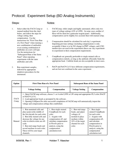
Protocol: Experiment Setup (BD Analog Instruments)1.Select either the FACS Comp or manual method from the chart below, and follow the steps for voltage setting, then compensation. Use theinstructions for “First-Time Run of a New Panel” when running a new combination of antibodies or an existing combination of antibodies on a new cell e the instructions for“Subsequent Runs of the Same Panel” when repeating experiments with the same antibodies and cells.2.Run experiment samples,followed by appropriate shutdown procedures for the instrument.1.FACSComp, while simple and highly automated, offers only two types of voltage settings (LW or LNW). In some cases, neither of these will be ideal for a particular reagent panel. Additionally,compensation can be slightly less accurate than with manual setup.2.Compensation should be calculated for each day’s experiment.Importing previous settings (including compensation) is onlyacceptable if there is to be NO change in PMT voltages, and if NO tandem dyes are used in the experiment (these can vary experiment-to-experiment in their compensation requirement).3.CompBeads are generally preferable to single-stained cells ascompensation controls, as long as the antibody efficiently binds the appropriate bead. Calibrite beads are also acceptable in most cases.4.PerCP and PerCP-Cy5.5 have different compensation requirements,and are best not combined in the same experiment.Steps:Notes:1. Run mid-range beads, and adjust voltages (if needed) to place medians within 10% of the target channel for each color.Voltage Setting1. Run unstained cells and place peak in the middle of the first decade for each color.2. Run fully stained cells and decrease the voltage for any color in which events are off-scale.3. Run mid-range beads and record medians in each color.These will be your target channels.1. Open FACSComp software, choose 3- or 4-color LNW or LW setup and appropriate FL3 color (PerCP or PerCP-Cy5.5).2. Load appropriate beads as prompted by the software.3. Opening CellQuest Pro after successful completion of FACSComp will automatically import the voltage and compensation settings thus established.Voltage SettingCompensationCompensation1. Run single-stained CompBeads for each color.2. Acquire with compensation off,and calculate compensation in FlowJo prior to analysis, using the compensation calculation tool.1. Run single-stained CompBeads for each color.2. Acquire withcompensation off, and calculate compensation in FlowJo prior to analysis, using the compensation calculation tool.ManualFACS CompSubsequent Runs of the Same Panel First-Time Run of a New Panel OptionProtocol: Experiment Setup (BD Analog Instruments)Reagent Recommendations:Use 1 drop + 350 µL FACS Flow buffer.556298 (Sphero rainbow particles, mid-range FL1 fluorescence)BD Mid-range beads Use 1 drop per sample. Negative CompBeads can be included in each tube and/or run as a separate negative control (the latter is preferable).552843 (anti-mouse κ)552844 (anti-rat κ)552845 (anti-rat/hamster κ)BDCompBeadsUse 1 drop + 350 µL FACS Flow buffer.340486 (unlabeled, FITC, PE, PerCP beads)340487 (APC beads)345036 (PerCP-Cy5.5 beads)BD Calibrite beadsInstructions for UseCatalog Number Reagent。

OPERATOR’S MANUALFORVarian 356-LCControl Software Polymer Laboratories Ltd, Now a part of Varian, Inc., Essex Road, Church Stretton,Shropshire SY6 6AX, UKTel +44 (0)1694 723581, Fax +44 (0)1694 722171, Service Tel +44 (0)1694 724333Polymer Laboratories, Varian, Inc., Amherst Fields Research Park, 160 Old FarmRoad,Amherst, MA 01002, USA Tel +1 413 253 9554, Fax +1 413 253 2476Polymer Laboratories, Varian B.V., Herculesweg 8, 4339 PL Middelburg,The Netherlands Tel +31 (0) 118 671500, Fax +31 (0)118 671502Polymer Laboratories, Varian Belgium NV SA, Mechelsesteenweg 362,2860 St.-Katelijne-Waver, Belgium Tel +32 (0) 15 556460, Fax +32 (0) 15 556186Polymer Laboratories, Varian Deutschland GmbH, Alsfelder Stra€e 6,D-64289 Darmstadt, Germany Tel: +49 (0) 6151 7030 Fax: +49 (0)6151 703237Varian S.A.,7 Avenue des Tropiques, Z.A. Courtaboeuf, B.P. 12F-91941 Les Ulis Cedex, France Tel +33 1.6986.3838 Fax: +33 1.6928.2308Please note that Varian, Inc. is now part of Agilent Technologies. For more information, go to /chem.CONTENTS1GENERAL INFORMATION3 1.1I NTRODUCTION (3)1.2S PECIFICATIONS (4)1.3C ONNECTING THE V ARIAN 356-LC TO A PC (5)1.3.1Use a Universal Serial Bus Interface (USB)51.3.2Adding an Extra Serial Card to your PC -Using Multiple Serial Ports5 1.4U SING S TAR W ORKSTATION WITH I NSTRUMENT C ONTROL S OFTWARE (5)1.5I NSTALLATION P ROCEDURES-S OFTWARE (7)1.5.1Installation of the PL Instrument Control Software from CD71.5.2Installation of the PL Instrument Control On-line Help from CD71.5.3Configuring the PL Instrument Control Software8 2THE GRAPHICAL USER INTERFACE10 2.1O VERVIEW (10)2.2S UMMARY V IEW (11)2.3C OMPONENT V IEW (11)2.4A UTOMATING THE V ARIAN 356-LC (12)3TROUBLESHOOTING14 3.1E RRORS (14)3.2V ARIAN 356-LC E RRORS (15)1General Information1.1IntroductionThe Varian 356-LC differential refractometer is a universal detector designed for high-performance analyses where the refractive index of a flowing liquid with respect to a reference is required. Its small cell volume, high sensitivity, and accurate temperature control make it well-suited for use as a detector in automated and manual high performance liquid chromatography.The Varian 356-LC RI detector can be operated as an integrated module within a Liquid Chromatography System using Galaxie™ Chromatography software. Alternatively, the detector can be used as a stand-alone HPLC detector through serial communications.This manual instructs the user how to install the PL Instrument Control software for operation of the Varian 356-LC RI as a stand-alone detector. For information on operating the detector please refer to the Operation manual.1.2SpecificationsRI range 1.0~1.75 RIURange 150-600x10-6/FS RIULinearity 600 ‚RIUSensitivity LOW (2), MED (4), HIGH (8) mV/‚RIUShort-term noise 1<5.0x10⁻⁹RIUDrift <2.5x10⁻⁷RIU/hourResponse time 0.1-5.0 secTemperature control OFF, 30-50 ƒC (1 ƒC increments)Cell volume 6 ‚LLight source LED 880 nmAnalogue output 1 V FSDDigital output24 bit (10 Hz) via serial portPolarity Positive/NegativeExternal communication RS232Autozero YESPurge YESFlow rate range0.1-10 mL/minPressure rating100 kPa (15 psi)Internal volume-inlet15 ‚LInternal volume-outlet459 ‚LTotal internal volume Normal operation 474 ‚LPurge mode 491 ‚LWetted material 316 SST, Quartz Glass, PTFE, PerfluoroelastomerPower requirements AC 100~240 V 50/60 HzPower consumption150 W (max)Dimensions (wxdxh)(unpacked)296 x 475 x 212 mmDimensions (packed)460 x 775 x 385 mmWeight (unpacked)11 kgWeight (packed)13.5 kgPC Requirements Windows…2000 & XPproRemote operation Remote purge & autozeroSafety features Error and leak detectionTable 1.Performance Specification of the Varian 356-LC RI Detector1According to ASTM method E-1303-95 “Practice for Refractive Index Detectors used in Liquid Chromatography”. Detector conditions; temperature 35 ƒ C, response time 4 sec.1.3Connecting the Varian 356-LC to a PC1.3.1PC RequirementsTo operate the Varian 356-LC detector using the Instrument Control Software, a free Serial (RS-232) communications port (1 to 255) is required on your PC. Mostcomputers are supplied with at least one serial port as standard, but if your PC does not provide a serial port, please see section 1.3.1.1& 1.3.1.2The Varian 356-LC Instrument Control Software is only compatible with Windows…2000 & XP Pro.1.3.1.1Use a Universal Serial Bus (USB)to Serial InterfaceIf your PC has one or more Universal Serial Bus (USB) connectors then you can use a “USB –Serial Port Adaptor” (part # 0860-0620), which provides a Serial Port connection to your PC. The Universal Serial Bus interface is supported on:④ Windows 98④ Windows ME④ Windows 2000④ Windows XPUSB is NOT Supported on NT 4.0. You may require extra software to use USB on Windows1.3.1.2Adding an Extra Serial Card to your PC -Using Multiple Serial Ports Multiple Port Serial cards are available, which allow 4, 8 and 16 extra serial ports to be added to your PC using a single PCI card.1.3.2Serial ConnectionEnsure that the Varian 356-LC detector is switched on and operating normally. Make sure you have one free and valid RS-232 communications port (1 to 255).Connect the serial port on your PC to the port labelled "RS232" on the rear of the detector, using the serial cable provided. Ensure that the flash upgrade switch, (see figure 1) is located in the RUN position (i.e. downwards).1.4Instrument Control for non-Galaxie UsersThe Varian 356-LC was designed to integrate fully into Galaxie Chromatography software, allowing the user to control the instrument,remotely for unattendedoperation.However, for non-Galaxie users (e.g. Star or MS workstation)the Varian 356-LC Control software (v2.2), provides a standalone control of the Varian 356-LC NOTE !The 356-LC Instrument Control software provides direct control of the Varian 356-LC, via the RS232 port, in much the same way as front panel control. It does not provide data acquisition.For data acquisition and control, the Control software must be used in conjunction with a chromatographic data acquisition package,such as Star or MS Workstation. The Varian 356-LC’s analogue data can be collected by connecting the supplied analogue output cable (Part No. PL0880-0310) from the rear of the detector (see figure 1) to an A/D interface (e.g.Star MIB 800 module). Please refer to the Star or MS workstation user manual for more information on how to configure the Star 800 modules.Figure 1. Rear view of the Varian 356-LC RI Detector1.Serial RS232 connector –24 bit digital output2.Control firmware flash upgrade switch3.Connector control I/O –15 pin D type female4.Analogue output -‰1 V5.Mains switch6.Mains input1235461.5Installation Procedures-Software1.5.1Installation of the PL Instrument Control Software from CDPlace the CD-ROM containing the Varian 356-LC Control software into the CD drive. In most cases the CD browser window will automatically open. However if the window does not appear then select the Run option in the Start menu, and type in D:\launch.exe (where D: denotes the CD drive).From the CD browser window select the Install the Software option and follow the on-screen instructions, it is recommended that the default settings are selected.Ensure that when you log on to the PCyou have full administration rights.You may need to restart your computer at the end of installation; if this is required you will be prompted to do so.After successful installation of the Control software, the program is simply run by clicking on the application named PL Instrument Control (PLInstControl.exe) installed in the PL Instrument Control group of the Programs option in the Start menu.The default location for the program files will be C:\Program Files\Polymer Laboratories\PL Instrument Control, which contains the following files:-Before running the program thesoftware must be first configured,see section 1.5.3.1.5.2Installation of the Instrument Control On-line Help from CDFrom the CD browser window select the Install Online Help option and follow the on-screen instructions, it is recommended that the default settings are selected. Thetwo help files (one for the PL Instrument Control software and the other for the PL Instrument Configuration Editor program) will be installed and the default location will be C:\Program Files\Polymer Laboratories\PL Instrument Control\Docs.1.5.3Configuring the Instrument Control SoftwareThe Control Software needs to be closed down before startingthis program.The configuration of the Varian 356-LC should normally be doneby a qualified Varian representative.To configure the Control software for the Varian 356-LC, you need to run the PL Instrument Configuration Editor to define the components that make up the instrument. The PL Instrument Configuration Editor is simply run by clicking on the application named PL Instrument Configuration Editor (PLInstConfigEd.exe) installed in the Service group of the PL Instrument Control group of the Programs option in the Start menu.The first time the PL Configuration Editor program is run, theprogram displays all the components that are available forcontrol.For the initial configuration of the system select the Varian 356-LC from the list by left clicking on the name of the component so that the configuration matches the instrument.Once the Varian 356-LC configuration has been completed the correct Com port needs to be assigned. To set the Com port, double click on the component name. The Configure Component dialog will open, where the correct Com port can be entered.Once the Com ports is set correctly, close the configuration editor and wait while the new configuration is saved. While the new configuration is being saved the following message will be displayed: -Updating the instrument configuration cantake up to a minute so please bepatience.For further information on configuring a system then please see the on-line help within the PL Configuration Editor program.Chapter 2-The Graphical User Interface2The Graphical User InterfaceTotal instrument control of the Varian 356-LC is provided by a Windows-based Graphical User Interface (GUI). This intuitive interface provides simplistic control as well as a comprehensive monitoring system.For further information on the PL Instrument Controlsoftware please see the on-line help within theprogram.To start the 356-LC Control software, select the PL Instrument Control item in the PL Instrument Control program group of the Programs option in the Start menu. 2.1OverviewThe Control screen is effectively divided into two main Views, these are:1.The Summary View2.The Component View2.2Summary ViewThe summary view displays the status of the Varian356-LC and a quick way of accessing the various parameters and options available within the PL Instrument Control software.A green LED next to the Varian 356-LC name indicates the module is being controlled and running whereas a red LED would indicate the module is either not running or not controlled.For further information on the Summary View please see the on-line help within the PL Instrument Control software.2.3Component ViewThe component view provides direct access to the Varian 356-LC control parameters. In general each component view contains a number of common items and options. The actual items available in a view are dependent on the component selected.The general component view for all components except for autosamplers/carousels is shown below.Status Bar–This displays Varian 356-LC description and current status.On-line Help Button–This is a direct link to the on-line help for that component view. Parameter Grid–This displays the current set parameter(s) for the 356-LC. To set and update the parameter(s) enter the required value(s) in the Set Value column and press the UPDATE button.To undo any parameter(s) prior to pressing the Update button press the Undo button,.To reset the parameter(s) back to the default value(s) press the Factory Reset button, .Help Output Window–This displays a simple summary help for each parameter and action. To view this information, select the parameter or action. The information displayed in the Help Window will be a short description about the action or parameter, the Factory Default Value and the Minimum and Maximum Values for the parameter.Action Button(s)–The Varian 356-LC can be Purged or Autozeroed using the Action Buttons, as well as from the Action List. To run an action, press the required Action button.Press the STOP button, to stop all the procedures currently running on the selected component.For information on the Toolbar menus please see the on-line help within the PL Instrument Control software.2.4Automating the Varian 356-LCThe Instrument Control software provides the ability to automate the control of the Varian 356-LC using the Events Schedule Editor. To open the Events Schedule Editor and create a schedule, select the Edit Schedule option from the Automation menu on the toolbar. The editor will initially display a default Events Schedule consisting of a single Process and Sequence entry. This ensures you only have to add a Procedure entry for the schedule to be valid.To add a Procedure right click on the Sequence entry in the schedule, the Procedure Details window will open where the required action can be selected.Once the Events Schedule is completed press the Start button, to start the schedule.The schedule can be used to equilibrate the detector by automatically purging a autozeroing the detector.Message boxes can be displayed at key stages during an Event Schedule. These message boxes require user input before the rest of the schedule can be run. The text displayed in the message box is customisable allowing simple status information or more detailed instructions to be displayed to the operator. Two examples of this are: -∙ Providing a simple guide path to an operator for the manual operation of the system.∙ Providing feedback / key information to an operator at key stages of a more automated system.For further information on the Event Schedule Editor please see the on-line help within the Instrument Control software.3Troubleshooting3.1ErrorsAny error(s) that occur with communications or operations (running component actions, updating parameters etc.) with the instrument, the Diagnostic Output Window will automatically open with the error(s) displayed in the Component Error Status Tab of the Diagnostic Output Window as shown below. Each error is uniquely identified with a number that can be referenced back to the control code.Figure 2.Diagnostic Output WindowNote:The information displayed in last two Tabs is primarily for service diagnostics and the Window does not need to be open for normal operation of the instrument.If an error is displayed it needs to be cleared in order for the diagnostic window to be closed, allowing access back to the PL Instrument Control software. To clear an error press the Select button to highlight the row and press the Clear button. Multiple errors can be selected at a time. Once all errors have been cleared the diagnostic window can be closed.Clearing an error will stop all procedures that are running and attempting to communicate with the component. To re-establish communications with the component either select the Reconnect option from the Instrument menu or return to the component view and resend the parameters or repeat the required action.The errors that can be displayed from the software are listed on the following pages.3.2Varian 356-LC ErrorsGeneral System ErrorsError Cause(s)ActionCould not initialise specified comms port Incorrect Com portassigned to thecomponent, the PL-GPC50 Plus is not poweredon or the USB cable isnot connected.Ensure the correct Com port has beenassigned within the PL InstrumentConfiguration Editor program. Ensurethe PL-GPC 50 Plus is powered on andthe USB cable is connected.No response received from the device Incorrect Com portassigned to thecomponent orcommunications lost withthe component, e.g.power failure.Ensure the correct Com port has beenassigned within the PL InstrumentConfiguration Editor program. Ensurethe PL-GPC 50 Plus and/or componentis powered on. If assigned Com port iscorrect and the system is powered onthen contact Polymer Laboratories oryour local agent.Unrecognised response from the device Turn the PL-GPC 50 Plus off and then on again (ensure the control software has been closed before turning the instrument off). If this error persists then contact Polymer Laboratories or your local agent.The device rejected the last command Incorrect componentassigned to the Comport.Ensure the correct component hasbeen assigned to the correct Com portwithin the PL Instrument ConfigurationEditor program.The device returned an error The component failed tocomplete an action.Reinitialise the component from the PLInstrument Control software and ensurethe initialisation is completedsuccessfully. Otherwise turn the PL-GPC 50 Plus off and then on again(ensure the control software has beenclosed before turning the instrumentoff). If unsuccessful and no obviouscause for the error then contactPolymer Laboratories or your localagent.Instrument ErrorsError Cause(s)Action01Fan stopped/failed Fault with the circuitry/wires/fan. Callyour Varian customer supportrepresentative if this happens regularly.02Upper leak detectorthermistor failure.Liquid sensor needs replacing. Call your Varian customer supportrepresentative.03Lower leak detectorthermistor failure.Liquid sensor needs replacing. Call your Varian customer supportrepresentative.04Internal vapour sensorfailure.Vapour sensor needs replacing. Call your Varian customer supportrepresentative.05External vapour sensorfailure.Vapour sensor needs replacing. Call your Varian customer supportrepresentative.06Liquid leak sensor hasdetected liquid in driptray.Liquid in the base of the unit -Stop pump and investigate.07High concentration ofvapour detected outsideof unit.Ensure sufficient ventilation around themodule.Check for a solvent leak.08Heated block thermistorbelow minimumthreshold.Call your Varian customer supportrepresentative.09Heated block thermistorabove maximumthreshold.Call your Varian customer supportrepresentative.0A Light source error Replace the light source assembly. Callyour Varian customer supportrepresentative.Auto-Zero (01)Autozero timeout Re-autozero the detector.。

科学已很复杂,流式要更简单!1. CFlow软件介绍你可以通过Accuri CFlow或者CFlow Plus软件控制C6流式细胞仪,实现数据获取,生成统计数据以及分析结果等操作。
CFlow功能强大,而且简单易用。
CFlow软件具有以下特性:有收集,分析,统计三个查看面板。
Plots可以显示超过106的数据动态范围。
可以随时进行数据分析和补偿调节。
可以拖拉plots。
以FCS 3.0格式输出文件。
C6格式数据可以准确无误的转换为FCS格式数据。
1.1 安装CFlow这样安装CFlow:1. 确保没有用USB连接计算机和C6流式细胞仪。
2. 打开计算机和显示器。
3. 插入CFlow软件CD光盘或者Accuri提供的U盘,当准备完毕,双击CFlowInstaller.exe文件。
4. 按照安装向导的提示进行安装。
1.2 启动CFlow先安装并设定好C6流式细胞仪,再运行CFlow软件(请参考C6 Flow Cytometer 安装手册)。
这样打开CFlow软件:1. 双击计算机桌面上的CFlow图标,CFlow会打开一个新的空白的工作面板。
注意:如果CFlow显示信息Extra startup time needed due to cleaning or improper shutdown, C6会比平时多用几分钟完成恢复,然后回到绿灯准备完毕状态。
当对仪器进行首次安装时,你可能会遇到这种情况。
如果不小心关闭仪器电源,也会出现这种情况。
1.3 CFlow工作面板(Workspace)CFlow的主工作窗口叫做CFlow Workspace,这个工作面板包含获取和分析数据所需的所有控制以及显示功能面板。
CFlow工作面板分为三个控制面板:收集面板(Collect)—包括设定数据收集以及数据获取条件的控制命令(第3章有详细说明)。
分析面板(Analyze)—包含数据分析的控制命令(第4章有详细说明)。
统计面板(Statistics)—显示统计学信息(第5章有详细说明)1.4 打开一个新的CFlow工作面板当打开CFlow,会显示一个不带任何用户设置的空白工作面板,你可以使用这个新的工作面板来建立自己的分析模板。
金和OAC6产品功能清单模块列表金和C6的详细产品功能清单和模块列表,包含金和的详细功能清单和模块说明。
独家整理。
金和C6功能清单目录一、工作台模块功能清单............................................................. .. (2)二、公文管理模块功能清单............................................................. (3)三、流程管理模块功能清单............................................................. .. (5)四、个人事务模块功能清单............................................................. .. (6)五、信息发布模块功能清单............................................................. .. (9)六、信息交流模块功能清单............................................................. (10)七、知识管理模块功能清单............................................................. (12)八、行政管理模块功能清单............................................................. (13)九、人力资源模块功能清单............................................................. (15)十、客户关系模块功能清单............................................................. (17)十一、综合分析模块功能清单............................................................. . (19)十二、系统管理模块功能清单.............................................................. (20)金和C6的详细产品功能清单和模块列表,包含金和的详细功能清单和模块说明。
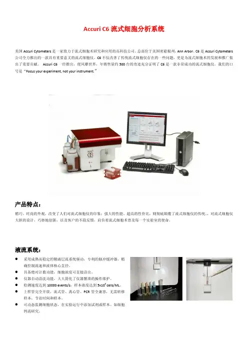
Accuri C6流式细胞分析系统美国Accuri Cytometers 是一家致力于流式细胞术研究和应用的高科技公司。
总部位于美国密歇根州,Ann Arbor 。
C6是Accuri Cytometers 公司全力推出的一款具有重要意义的流式细胞仪。
C6不仅改善了传统流式细胞仪存在的一些问题,更是为流式细胞术的发展和推广做出了重要贡献。
Accuri C6一经推出,便风靡世界,年销售量约500台的奇迹充分证明了C6是一款非常成功的流式细胞仪。
我们的口号是“Focus your experiment, not your instrument.”产品特点:精巧、时尚的外观,改变了人们对流式细胞仪的印象;强大的性能、超高的性价比,则彻底颠覆了流式细胞仪的传统。
,对流式细胞仪大胆的设计,巧妙地创新,以及客户的不段反馈,肩负着流式细胞术普及每一个实验室的使命。
液流系统:●采用成熟而稳定的鞘液层流系统驱动,专利的脉冲缓冲器,精确控制流速和流体核心直径。
●具备绝对计数功能,细胞浓度可直接读出。
●仪器自动清洗功能,大大简化了仪器繁琐的操作维护。
●检测速度达到10000 events/s ,样本浓度达到5x10⁶ cells/ML 。
●上样管完全开放,流式管、离心管、PCR 管全兼容,无需转移样本,节省时间和样本。
● 可动态监测细胞状态,在实验运行中添加试剂或样本。
如细胞钙流研究。
光学系统:配备了蓝色和红色的双激光光源●4通道6参数分析型流式细胞仪,可更换滤光片设计,提高了客户实验荧光标记的的灵活性。
●精巧光路设计,高质量光学组件,仪器移动后无需校正。
分析系统:●动态范围超过了7个数量级,保证了实验数据的客观完整性。
●ZOOM功能可以显示任何大小数量级的数据,实现精确设门。
●简便易学,30min即可完全掌握软件操作,注重客户结果分析。
自动化模块:●CSampler大样本客户的完美解决方案●兼容48孔板、96孔板及深孔板,并且可用于12×75mm的24位管架。

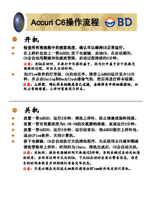
Accuri C6操作流程 开机检查所有液流瓶中的液面高度,确认可以维持C6正常运行。
检查所有液流瓶中的液面高度,确认可以维持C6正常运行。
C6正常运行 在上样针处放上一管ddH2O,按下电源键,启动C6 在启动期间, ddH2O,按下电源键 C6, 在上样针处放上一管ddH2O,按下电源键,启动C6,在启动期间, C6会自动用鞘液冲洗液流管路,启动过程持续约5分钟。
C6会自动用鞘液冲洗液流管路,启动过程持续约5分钟。
会自动用鞘液冲洗液流管路注意: C6启动时,不要打开仪器的盖子, 注意:当C6启动时,不要打开仪器的盖子,因为打开盖子会干扰激光 启动时 预热的过程,并延长启动时间。
预热的过程,并延长启动时间。
当CFlow软件的灯变绿,C6启动完毕。
推荐上ddH2O运行至少15分 CFlow软件的灯变绿,C6启动完毕。
推荐上ddH2O运行至少15分 软件的灯变绿 启动完毕 ddH2O运行至少15 并点击Unclog Backflush排除气泡 然后再进行样本检测。
Unclog和 排除气泡, 钟,并点击Unclog和Backflush排除气泡,然后再进行样本检测。
注意:上样前,确认样本细胞是否已过滤,去除样本中的细胞团块, 注意:上样前,确认样本细胞是否已过滤,去除样本中的细胞团块,以 防止管路堵塞;上样时需要混匀样本。
防止管路堵塞;上样时需要混匀样本。
关机放置一管ddH2O,运行2分钟,清洗上样针,防止堵塞或染料残留。
放置一管ddH2O,运行2分钟,清洗上样针,防止堵塞或染料残留。
ddH2O 放置一管有效氯浓度为0.5% 1%的次氯酸钠溶液 高速运行2分钟。
0.5%- 的次氯酸钠溶液, 放置一管有效氯浓度为0.5%-1%的次氯酸钠溶液,高速运行2分钟。
放置一管ddH2O 运行2分钟,运行结束后, ddH2O留在上样针处 ddH2O, 留在上样针处。
放置一管ddH2O,运行2分钟,运行结束后,将ddH2O留在上样针处。
如何用FlowJo分析Accuri C6数据作者:蔡何清, FlowJo 技术专员目前市场有很多流式仪器,包括几家大的公司如BD,贝克曼等。
FlowJo做为一款优秀的流式数据分析软件,可以兼容几乎所有流式仪器采集的数据,可以弥补其它机器自带软件的分析功能不足的缺憾,这也是FlowJo备受欢迎及推崇的原因。
今天将详细介绍如何用FlowJo来分析BD公司的机器Accuri C6采集的数据。
Accuri C6是一款全功能、双激光的小型桌面流式细胞仪,有其独特的优势。
但是Accuri C6自带的CFlow软件在分析流式数据方面还存在一些进步的空间,比如:缺乏完善的图片叠加功能,尤其是其直方图叠加的效果有待加强;缺乏细胞周期分析工具、增殖分析工具以及动力学分析工具。
FlowJo是目前直接可以和它兼容的流式数据分析专业软件,满足用户的数据分析要求。
实际上,用FlowJo分析Accuri C6的流式数据与用FlowJo分析其他流式细胞仪采集的流式数据是一样的。
只不过由于Accuri C6在采集数据的时候不需要设置电压等特点,在分析Accuri C6数据的时候要做一些简单的处理。
这篇博文将对这些处理步骤做详细的介绍。
一、在Accuri C6将数据导出为FCS格式ISAC制定的流式数据的标准格式为FCS格式,Accuri C6的CFlow软件默认的数据保存格式为其特有的C6格式。
因此,在用FlowJo分析Accuri C6数据之前,需要将数据转换为FCS格式。
可参考下面的操作步骤:1. 打开CFlow软件,点击File菜单,在下拉菜单中选择Open CFlow File or Template,导入采集到的C6格式的数据2. 点击File菜单,在下拉菜单中选择Export FCS File或者Export ALL Sample as FCS二者的区别是:Export FCS File:将选定的某个 data well (sample) 输出为FCS格式的数据,并保存到用户自建的文件夹里Export ALL Sample as FCS:将所有的data well (sample) 输出为FCS格式的数据,并保存到“CFlow-FCS Exports”文件夹里,这个文件夹一般在桌面上图1二、调节坐标轴的范围由于Accuri C6在采集数据的时候不需要设置电压,而且C6能够采集到的信号范围位于1-16777216(100-107.22),流式图中的细胞群可能会由于坐标轴的范围过大而被压缩在左下角的位置,如图2所示:图2这时我们需要合理调节坐标轴的范围,使细胞群显示于流式图的中间位置,从而能明显地看到细胞分群,便于我们设门。
BD Accuri C6 Plus开关机操作流程1.开机1.1 检查所有瓶中的液体, 鞘液桶补满超纯水(2L), 废液桶倒空;清洗液和消毒液不是空的。
清洗液:1% BD FACS Cleaning solution(原液为10%, 即稀释十倍使用)1.2消毒液: BD detergent solution concentrate (1.5ml BD detergent solution +98.5 ml ddH2O)机前确保样品支架上, EP管内至少装500uL ddH2O。
仪器启动期间, 软件界面上仪器当前状态会显示黄色的灯, 该过程中仪器会用鞘液冲洗液流管路, 持续大约13分钟, 直到显示绿灯表示仪器和软件连接完成。
2.关机2.1 上样完毕后, 用SIP程序清洗进样针, 根据提示先上2ml 1% FACS Clean, 再上2ml ddH2O;2.2 保证清洗液和消毒液的量, 在进样针上放2ml ddH2O, 轻触(不能超过3秒)仪器上电源键, 仪器自动运行13min cleaning the fluidics程序, 后自动关机;2.3请清理台面, 做好记录。
3.仪器维护3.1 在上样针下放一个空管, 点击backflush, 进行排气泡或者排堵;一个月或者觉得仪器运行杂质比较多时, 可运行●3.2Extend flow cell clean, 仪器会在流动室充满清洗液的情况下自动关机, 使流动室充分浸泡在清洗液中:至少500ul Extend flow cell clean●在上样针处放solution;Instrument菜单下点击Extended clean of flow ●在cell;, 然后自动关机, 至少2h后再●仪器会吸入延长清洗液重启, 也可延长浸泡时间甚至过夜;重启计算机, 上一管2ml的水, C6会运行一个长液流启动循环, 将清洗液从流动室中排出;仪器状态显示绿灯后, 正常操作即可。
Accuri C6日常开机步骤
1在进样针(SIP)处放置1 ml 去离子水。
2 打开仪器左下部位的电源,开启流式细胞仪。
3 双击打开桌面Cflow plus 软件快捷方式,检查确定仪器状态正常,即“交通灯”指示为绿
色。
4 在进样针(SIP)处放置1个空样品管,点一次unclog,然后点一次Backflush。
取走样品管。
5 取新样品管,在进样针(SIP)处放置2 ml 去离子水,高速运行2 分钟。
6 上样品检测
Accuri C6 关机步骤
1在进样针(SIP)处放置1 ml去离子水。
2 选择一个空白孔。
3选择高速(fast setting)运行,设定运行时间为2 分钟。
4点击运行按钮。
5 运行结束后,关机软件,保存数据。
进样针(SIP)处放置的去离子水保持浸没。
6关闭仪器左下部位的电源,按一下即可,关闭流式细胞仪(约13分钟自动关闭)。
注:关机后C6会继续运行一段时间,自动停止工作。
*如果涉及到有PI染料的检测,在收集完数据后,在进样针(SIP)处放置1 ml去离子水,高速(fast setting)运行2min,然后再执行关机操作,以此进一步消除PI这种粘性细胞染料对后续实验的影响。
使结果更准确。
流式细胞仪Accuri C6一、启动Accuri C6仪器①依次开仪器电源、电脑显示器及主机电源②5~10分钟后,双击电脑桌面“CFlow Plus”图标,进入仪器控制软件界面。
软件界面信号灯指示为黄色,显示仪器与电脑没有连接好;软件界面信号灯指示为绿色,显示仪器与电脑已连接好③检查仪器旁边四个液体容器,清空“Waste”桶中的废液,检查“Sheath”、“Cleanning fluid”、“Decontamination”三个桶中液体量是否满足实验要求,若存放时间超过1个月,则需要进行更换。
其中“Sheath”为超纯去离子水,“Cleanning fluid”有效氯离子为1%的次氯酸钠,“Decontamination”为细菌消毒液,1295µl杀菌液原液用超纯水定容250ml④载物台上放置空管,点击软件界面Instrument/Run backflush cycle,可以看见少许液体从进样针中流出来,作用为反冲,清除进样针中的残留物⑤在软件96孔板界面中任选1孔,载物台上放置1管去离子水,⑥选择运行速度为“High”,运行时间设置为10分钟,点击“Run”按钮运行10分钟自动停止。
该步骤的作用是:激光器预热,清晰管路⑦该孔收集数据后变为蓝色,鼠标选中该孔,点击“Delete Sample Data”,删除孔内数据,启动步骤完成,即可开始检测样品二、Accuri C6样品检测①将样品放置在载物台上,在软件96孔界面选择样品的位置,并命名②设置检测停止条件。
(1)无限制检测Run unlimited,手动点击停止;(2)收集多少个细胞后停止,在events框中填写;(3)收集多长时间停止,在min和sec框中填写;(4)收集多少体积停止,在µl框中填写③在Fluidics框设定进样速度,可选择慢速、中速和快速,或者在Custom框中手动设置进样速度④“Set Threshold”设定阈值,需要根据实验设定合适的阈值,阈值设置太低,背景荧光对目标细胞的荧光信号产生较大的干扰,阈值设置太高,无法有效检测目标细胞⑤“Set Color Compensation”设定颜色补偿,一般在数据处理分析过程中进行⑥点击“Run”按钮,开始样品检测三、样品检测过程中注意事项:①样品之间无需用去离子水冲洗,当完成所有样品检测时,必须运行Instrument/Cleanning fluid cycle清晰程序。