升压芯片FT8003
- 格式:pdf
- 大小:664.16 KB
- 文档页数:13

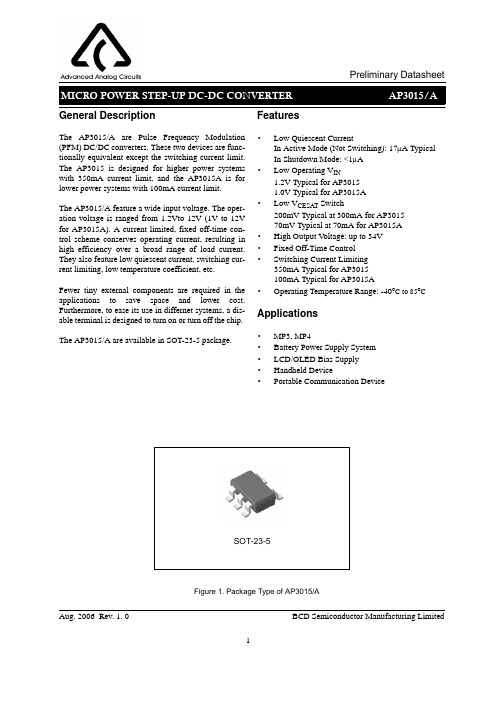
1Aug. 2006 Rev. 1. 0BCD Semiconductor Manufacturing LimitedGeneral DescriptionThe AP3015/A are Pulse Frequency Modulation (PFM) DC/DC converters. These two devices are func-tionally equivalent except the switching current limit.The AP3015 is designed for higher power systems with 350mA current limit, and the AP3015A is for lower power systems with 100mA current limit.The AP3015/A feature a wide input voltage. The oper-ation voltage is ranged from 1.2Vto 12V (1V to 12V for AP3015A). A current limited, fixed off-time con-trol scheme conserves operating current, resulting in high efficiency over a broad range of load current.They also feature low quiescent current, switching cur-rent limiting, low temperature coefficient, etc.Fewer tiny external components are required in the applications to save space and lower cost.Furthermore, to ease its use in differnet systems, a dis-able terminal is designed to turn on or turn off the chip.The AP3015/A are available in SOT-23-5 package.Features·Low Quiescent CurrentIn Active Mode (Not Switching): 17µA Typical In Shutdown Mode: <1µA ·Low Operating V IN1.2V Typical for AP3015 1.0V Typical for AP3015A ·Low V CESAT Switch200mV Typical at 300mA for AP3015 70mV Typical at 70mA for AP3015A ·High Output V oltage: up to 34V ·Fixed Off-Time Control ·Switching Current Limiting 350mA Typical for AP3015 100mA Typical for AP3015A·Operating Temperature Range: -40o C to 85o CApplications·MP3, MP4·Battery Power Supply System ·LCD/OLED Bias Supply ·Handheld Device·Portable Communication DeviceFigure 1. Package Type of AP3015/ASOT-23-52Aug. 2006 Rev. 1. 0BCD Semiconductor Manufacturing LimitedFigure 2. Pin Configuration of AP3015/A (Top View)Pin DescriptionPin NumberPin Name Function1SW Switch Pin. This is the collector of the internal NPN power switch. Minimize the trace area connected to this Pin to minimize EMI2GND Ground Pin. GND should be tied directly to ground plane for best performance3FBFeedback Pin. Set the output voltage through this pin. The formula is V OUT=1.23V*(1+R1/R2). Keep the loop between V out and FB as short as possible to minimize the ripple and noise,which is beneficial to the stability and output ripple4SHDN Shutdown Control Pin. Tie this pin above 0.9V to enable the device. Tie below 0.25V to turn off the device5V INSupply Input Pin. Bypass this pin with a capacitor as close to the device as possiblePin ConfigurationK Package (SOT-23-5)SW FBV INSHDNGND3Aug. 2006 Rev. 1. 0BCD Semiconductor Manufacturing LimitedSHDNV INBCD Semiconductor's Pb-free products, as designated with "E1" suffix in the part number, are RoHS compliant.Ordering InformationPackageTemperature RangePart NumberMarking IDPacking TypeSOT-23-5-40 to 85o CAP3015KTR-E1E6E Tape & Reel AP3015AKTR-E1E6FTape & ReelCircuit Type Package E1: Lead Free AP3015TR: Tape and Reel K: SOT-23-5-Blank: AP3015A: AP3015AFunctional Block DiagramFBFigure 3. Functional Block Diagram of AP3015/A4Aug. 2006 Rev. 1. 0BCD Semiconductor Manufacturing LimitedNote 1: Stresses greater than those listed under "Absolute Maximum Ratings" may cause permanent damage to the device. These are stress ratings only, and functional operation of the device at these or any other conditions beyond those indicated under "Recommended Operating Conditions" is not implied. Exposure to "Absolute Max-imum Ratings" for extended periods may affect device reliability.ParameterSymbolMinMaxUnitInput V oltageV INAP3105 1.212VAP3105A1.012Operating TemperatureT A-4085o CRecommended Operating ConditionsAbsolute Maximum Ratings (Note 1)Parameter Symbol Value Unit Input V oltage V IN 15V SW V oltage V SW 36V FB V oltage V FB V IN V SHDN Pin V oltageV SHDN 15V Thermal Resistance (Junction to Ambient, no Heat sink) R θJA 265oC/WOperating Junction Temperature T J 150o C Storage Temperature Range T STG -65 to 150o C Lead Temperature (Soldering, 10sec)T LEAD260o CESD (Human Body Model)3000V5Aug. 2006 Rev. 1. 0BCD Semiconductor Manufacturing Limited(V IN =V SHDN =1.2V , T A =25o C, unless otherwise specified.)Parameter Symbol Conditions Min TypMax Unit Input V oltageV INAP3015 1.212VAP3015A 1.012Quiescent Current I Q Not Switching 1730µA V SHDN =0V1Feedback V oltage V FB 1.2051.23 1.255V FB Comparator Hysteresis V FBH 8mV FB Pin Bias CurrentI FB V FB =1.23V 3080nA Output V oltage Line Regulation L NR 1.2V <V IN <12V 0.050.1%/V Switching Current LimitI LAP3015300350400mA AP3015A75100125Switch Saturation V oltage V CESATAP3015, I SW =300mA 200300mVAP3015A, I SW =70mA 70120Switch Off TimeT OFF V FB >1V 400nS V FB <0.6V1.5µS SHDN Input Threshold High V TH 0.9V SHDN Input Threshold Low V TL 0.25SHDN Pin Current I SHDN V SHDN =1.2V 23µAV SHDN =5V 812Switch Leakage CurrentI SWLSwitch Off, V SW =5V0.015µA Electrical CharacteristicsTypical Performance CharacteristicsUnless otherwise noted, V IN=1.2VFigure 4. Quiescent Current vs. Junction Temperature Figure 5. Feedback Voltage vs. Junction TemperatureFigure 6. Switch Off Time vs. Junction Temperature Figure 7. Shutdown Pin Current vs. Shutdown Pin VoltageAug. 2006 Rev. 1. 0BCD Semiconductor Manufacturing Limited67Aug. 2006 Rev. 1. 0BCD Semiconductor Manufacturing LimitedFigure 9. Switch Current Limit vs. Junction TemperatureTypical Performance Characteristics (Continued)Figure 10. Saturation Voltage vs. Junction Temperature Figure 11. Saturation Voltage vs. Junction TemperatureFigure 8. Switch Current Limit vs. Junction Temperature Unless otherwise noted, V IN =1.2V8Aug. 2006 Rev. 1. 0BCD Semiconductor Manufacturing LimitedFigure 13. EfficiencyTypical Performance Characteristics (Continued)Figure 12. Efficiency Unless otherwise noted, V IN =1.2VApplication InformationOperating PrinciplesAP3015/A feature a constant off-time control scheme.Refer to Figure 3, the bandgap voltage V REF (1.23V typical) is used to control the output voltage. When the voltage at the FB pin drops below the lower hysteresis point of Feedback Comparator (typical hysteresis is 8mV), the Feedback Comparator enables the chip and the NPN power switch is turned on, the current in the inductor begins to ramp up and store energy in the coil while the load current is supplied by the output capacitor. Once the current in the inductor reaches the current limit, the Current-Limit Comparator resets the 400ns One-Shot which turns off the NPN switch for 400ns. The SW voltage rises to the output voltage plus a diode drop and the inductor current begins to ramp down. During this time the energy stored in the inductor is transferred to C OUT and the load. After the 400ns off-time, the NPN switch is turned on and energy will be stored in the inductor again.This cycle will continue until the voltage at FB pin reaches 1.23V , the Feedback Comparator disables the chip and turns off the NPN switch. The load current is then supplied solely by output capacitor and the output voltage will decrease. When the FB pin voltage drops below the lower hysteresis point of Feedback Comparator, the Feedback Comparator enables the device and repeats the cycle described previously.Under not switching condition, the I Q of the device is about 17µA.The AP3015/A contain additional circuitry to provide protection during start-up or under short-circuit conditions. When the FB pin voltage is lower than approximately 0.6V , the switch off-time is increased to 1.5µs and the current limit is reduced to about 250mA (70mA for AP3015A). This reduces the average inductor current and helps to minimize the power dissipation in the AP3015/A power switch, in the external inductor and in the diode.The SHDN pin can be used to turn off the AP3015/A and reduce the I Q to less than 1µA. In shutdown mode the output voltage will be a diode drop below the input voltage.Typical ApplicationC1, C2: X5R or X7R Ceramic CapacitorL1: SUMIDA CDRH4D16FB/NP-100MC or EquivalentFigure 14. AP3015 Typical Application in LCD/OLED Bias SupplyC1, C2, C3: X5R or X7R Ceramic CapacitorL1: SUMIDA CDRH4D16FB/NP-100MC or EquivalentFigure 15. AP3015A Typical Application in 1 or 2 Cells to 3.3V Boost ConverterAug. 2006 Rev. 1. 0BCD Semiconductor Manufacturing Limited9Mechanical DimensionsSOT-23-5Unit: mm(inch)Aug. 2006 Rev. 1. 0BCD Semiconductor Manufacturing Limited10IMPORTANT NOTICEBCD Semiconductor Manufacturing Limited reserves the right to make changes without further notice to any products or specifi-cations herein. BCD Semiconductor Manufacturing Limited does not assume any responsibility for use of any its products for any particular purpose, nor does BCD Semiconductor Manufacturing Limited assume any liability arising out of the application or use of any its products or circuits. BCD Semiconductor Manufacturing Limited does not convey any license under its patent rights or other rights nor the rights of others.- Wafer FabShanghai SIM-BCD Semiconductor Manufacturing Limited 800, Yi Shan Road, Shanghai 200233, China Tel: +86-21-6485 1491, Fax: +86-21-5450 0008BCD Semiconductor Manufacturing LimitedMAIN SITEREGIONAL SALES OFFICEShenzhen OfficeShanghai SIM-BCD Semiconductor Manufacturing Co., Ltd. Shenzhen Office Advanced Analog Circuits (Shanghai) Corporation Shenzhen OfficeRoom E, 5F, Noble Center, No.1006, 3rd Fuzhong Road, Futian District, Shenzhen 518026, China Tel: +86-755-8826 7951, Fax: +86-755-8826 7865Taiwan OfficeBCD Semiconductor (Taiwan) Company Limited 4F, 298-1, Rui Guang Road, Nei-Hu District, Taipei, TaiwanTel: +886-2-2656 2808, Fax: +886-2-2656 2806USA OfficeBCD Semiconductor Corporation 3170 De La Cruz Blvd., Suite 105, Santa Clara,CA 95054-2411, U.S.A- IC Design GroupAdvanced Analog Circuits (Shanghai) Corporation 8F, Zone B, 900, Yi Shan Road, Shanghai 200233, China Tel: +86-21-6495 9539, Fax: +86-21-6485 9673BCD Semiconductor Manufacturing Limited。


升压芯片工作原理
升压芯片(Boost Converter)是一种电力转换器,其工作原理是通过电感和开关元件来实现将输入电压提高到输出电压的设定值。
具体工作过程如下:
1. 输入电压:升压芯片的输入电压为Vi。
2. 开关元件:通常使用MOSFET或BJT作为开关元件。
当开关元件导通时,电感储存能量,当开关元件关断时,电感释放储存的能量。
3. 电感:电感是升压芯片的重要组成部分,其作用是储存和释放能量。
当开关元件导通时,电感储存输入电压的能量,当开关元件关断时,电感释放储存的能量到输出端。
4. 整流元件:升压芯片输出端通常连接一个整流元件,如二极管。
整流元件的作用是将电感释放的能量导向输出端,并防止电流逆流到电感。
5. 输出电压:升压芯片输出电压为Vo,通过控制开关元件导通和关断的时间比例来调节输出电压的大小。
升压芯片的工作原理基于一个重要的电力转换原理:电感储能和释放能量。
通过控制开关元件的导通和关断时间,升压芯片能够将较低的输入电压提升到较高的输出电压,以满足特定的电路需求。

EK8003 同步升降压IC功能概述:◆宽工作电压2-38V,广泛用于升压电路或者降压电路,也可以用于既需要升压又需要降压的电路, 比如 车载电源,电瓶恒流充电,或者LED恒流电源。
◆PWM 信号调光功能:内部集成调光功能,能接受一个0-100%占空比的低频PWM 信号进行LED 亮度调节,也可以用作开关控制。
◆大功率:最大可以输出5A的电流,◆较小的PCB尺寸,5W尺寸仅为30*15*13mm。
管脚序号 管脚名称 功能描述1 GND 电源地端2 CT 频率控制端3 CE 开关控制端4 FB 电压检测端5 CS 电流检测端6 VDD 电源输入端7 LX 输出端8 EXT 外接MOS端电路框图应用1.应用2.应用指南:1) 电压计算:V OUT=1.27x(1+R3/R1),电流计算:I OUT=0.54V/R32) PWM/EN 端(3 脚)可以输入一个100~1000Hz 的低频PWN 信号进行亮度调节,如果不需调光则此端接地。
电感计算:一般来讲在输出相同电压的情况下,输出电流越小电感量要相对加大,而在输出相同电流的情况下,输出电压越高电感量要相对加大。
电感量调整不适当会发生电感响的问题。
4) 输出电容C3的计算:输出电流小的情况下可以用220uF,输出电流为300mA以上建议用470uF或者更大容量的电容,电容量小也会发生电感响的问题。
极限参数:参数 符号 测试条件件 最小值典型值 最大值 单位 工作频率 Fosc Ta=25℃ 20 300 KHz 工作电压 Vcc 2 38 V IC 各端极限电压 Vmax 38 V CE脚ON V CE0 1 V CE脚OFF V CE 2 38 V 电压检测端 V FB Ta=25℃ 1.24 1.27 1.3 V 调光频率 F PWM 100 500 1000 Hz LX最大输出电流 Iout 700 mA 电流检测端 SEN Vcc=3-36V Vpin3>V EN 0.510.54 0.57 mV 工作温度范围 Topr - 40 85 ℃储存环境温度 Tstg - 65 150 ℃焊接温度250±5℃ 260℃,10s抗静电强度 2000V 封装尺寸。
8003芯片
8003芯片是一款高性能、高集成度的芯片,广泛应用于各类电子产品中。
该芯片由中国科学院院士王建中和他的研究团队研发,具有以下主要特点和优势:
首先,8003芯片采用了先进的制程工艺,具有更低的功耗和更高的性能。
它采用了先进的22纳米制程技术,能够在低功耗下运行,延长电池寿命,节省能源。
同时,该芯片拥有多核心架构和超线程技术,使其运行速度更快、并发能力更强,可以满足各种高性能应用的需求。
其次,8003芯片具有极高的集成度。
该芯片集成了大量的功能模块,包括处理器核心、内存控制器、图形处理单元、多媒体引擎等。
这种高度集成的设计能够节省空间,简化电路板设计,降低成本。
同时,它还支持多种接口和标准,如USB、HDMI、以太网等,方便与其他设备进行连接和通信。
第三,8003芯片还具备良好的安全性能。
在现代社会中,网络安全和信息安全问题日益突出,安全性已经成为一款芯片的重要考量因素。
8003芯片采用了先进的硬件加密技术和安全启动机制,能够有效防止恶意攻击和非法入侵,保证用户信息的安全性。
最后,8003芯片拥有广泛的应用场景。
它可用于智能手机、平板电脑、智能家电、工业自动化等多个领域。
在智能手机领域,8003芯片能够提供流畅的多任务处理、高清视频播放等功能,让用户享受更好的使用体验。
在工业自动化领域,8003
芯片的高性能和低功耗可以帮助提高生产效率,降低能耗。
总之,8003芯片是一款高性能、高集成度、安全可靠的芯片。
它将为各类电子产品提供更好的性能和使用体验,推动科技的发展和社会的进步。
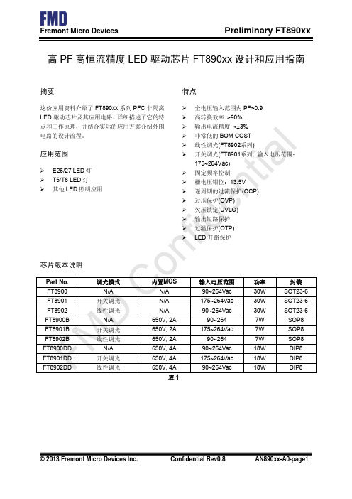
六单元IGBT 模块Six-Pack IGBT Module产品数据手册 Product Datasheet 版本 Ver.1806电路结构Circuit ConfigurationG6C5E6N33T12T11E5G5P3C6G4C3E4N22E3G3P2C4G2C1E2N11E1G1P1C2T22T21T32T31图1.电路结构Fig. 1 Circuit configuration模块外形Module Appearance图2. 模块外形Fig. 2 Module appearanceModule Label Code Instruction六单元IGBT模块Six-Pack IGBT Module 产品数据手册 Product Datasheet 版本 Ver.1806六单元IGBT模块Six-Pack IGBT Module 产品数据手册 Product Datasheet 版本 Ver.1806六单元IGBT模块Six-Pack IGBT Module 产品数据手册 Product Datasheet 版本 Ver.1806六单元IGBT模块Six-Pack IGBT Module 产品数据手册 Product Datasheet 版本 Ver.1806六单元IGBT模块Six-Pack IGBT Module 产品数据手册 Product Datasheet 版本 Ver.1806六单元IGBT模块Six-Pack IGBT Module 产品数据手册 Product Datasheet 版本 Ver.1806六单元IGBT模块Six-Pack IGBT Module 产品数据手册 Product Datasheet 版本 Ver.1806六单元IGBT模块Six-Pack IGBT Module 产品数据手册 Product Datasheet 版本 Ver.1806六单元IGBT模块Six-Pack IGBT Module 产品数据手册 Product Datasheet 版本 Ver.1806TG800FF08S1-S3A00六单元IGBT 模块Six-Pack IGBT Module产品数据手册 Product Datasheet 版本 Ver.180611Caution: This device is sensitive to electrostatic discharge. Users should follow ESD handling procedures.使用条件和条款(1)数据手册中的产品信息是专门为技术人员提供的。
第1共13页页ATM8F8040数据手册版本号更新时间更新内容V1.02020-09-05V1.0正式版本发布V1.12020-09-16V1.1版本发布,修正DNL参数V1.22020-12-10统一数据手册和应用手册的关于T2CAP的描述V1.32021-3-1增加16脚SOP16封装信息V1.42021-3-8更新IDD2测试条件第2页1.主要特色CPU 特性通信8位1T 8051内核支持两路UART 支持1/2/4/8系统分频模拟模块支持双DPTR 支持12路12位ADC 支持双线调试支持上电复位ROM支持低压复位16K 字节FLASH(擦写寿命1000次)时钟128字节EEPROM(擦写寿命10000次)内部时钟频率最高到32MHz,1%精度数据保持时间:10年内部时钟32KHz 低频振荡器RAM支持外部1-20MHz 晶振256字节内部IRAM 工作模式512字节外部XRAM 正常模式GPIO待机模式(IDLE)最多支持18个GPIO 停机模式(Stop),最小电流<1uA 支持任意端口变化中断工作条件Timer/PWM工作频率:最大32MHz 16位8051标准定时器T0/T1工作电压: 2.7~5.5V 带捕获和可编程输出的16位定时器T2工作温度:-40℃~85℃7路16位带互补输出PWM 输出模块封装唤醒Timer 20-TSSOP 看门狗定时器20-QFN 4x4SOP16其他CRC16循环冗余检测模块可配置逻辑计算单元(CPL)外部晶振停振检测1.主要特色 (2)2.概述 (4)2.1.说明 (4)2.2.应用方向 (4)3.设计框图 (4)4.引脚分布图 (5)5.封装尺寸图 (7)5.1.20-TSSOP (7)5.2.20-QFN (8)5.3.SOP16 (9)6.电气特性 (10)6.1.极限参数 (10)6.2.DC特性 (10)6.3.ADC特性 (11)6.4.内部高频振荡器特性 (11)6.5.内部低频振荡器特性 (11)6.6.外部振荡器特性 (12)6.7.存储器工作特性 (12)6.8.外部复位及中断管脚特性 (12)7.芯片选型 (13)2.概述2.1.说明ATM8F8040是一款内嵌16K字节FLASH的8位单片机。
bl8530 原理
BL8530是一个DC-DC升压稳压芯片,其原理基于PFM控制的开关型电路。
它的工作过程可以简单描述为:当BL8530的LX端内部的N沟道MOS场效应管为低电平时,电池对电感L充电蓄能;当LX端为高电平时,电池电
压与电感L两端产生的感生电压(此电压为电池电压的数倍)叠加后通过肖特基二极管给电容C2充电,这样在C2两端获得的便是升高的电压。
此外,BL8530具有的启动电压、高达200mA的负载驱动能力(当Vin=,ut=时),以及极低的静态功耗(Iq<),非常适合于便携式1~4节普通电池应用的场合。
在电路设计及生产中,BL8530针对开关电路固有的噪声问
题进行了改良,极大的减小了对其周边电路的干扰。
以上信息仅供参考,如需了解更多信息,建议查阅BL8530芯片的规格书或咨询相关技术人员。