产品规格书火炬-贴片排阻RCA规格书TH019-A-07
- 格式:pdf
- 大小:2.00 MB
- 文档页数:17

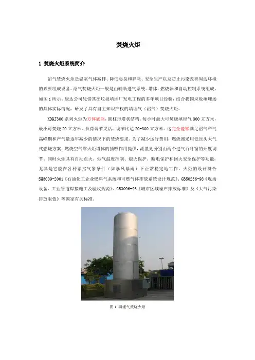
焚烧火炬1 焚烧火炬系统简介沼气焚烧火炬是温室气体减排、降低恶臭和异味、安全生产以及防止污染改善周边环境的必要组成设备。
沼气焚烧火炬一般是由辅助进气系统、塔体、燃烧器和自动控制系统组成,如图1所示。
康达公司凭借其在垃圾填埋厂发电工程的多年项目经验,结合我国垃圾填埋场的具体实际情况,研发了具有自主知识产权的填埋气(沼气)焚烧火炬。
KDHJ300系列火炬为方体底座,圆柱形塔状结构。
每小时最大可焚烧填埋气300立方米,最小可焚烧20立方米。
负荷调节灵活,调节比达20-300立方米。
这完全能够满足沼气产气高峰期和产气量逐年减少的情况下的焚烧要求。
为了减少运行费用,燃烧器采用低压头大气式燃烧方案,燃烧空气靠火炬塔体的抽吸作用提供,流量则分别由两个进气百叶窗的开度调节。
同时火炬具有自动点火、烟气温度控制、熄火保护、断电保护和回火安全保护等功能,尤其是它能在各种恶劣气象条件(如暴风暴雨)下正常稳定地工作。
火炬的设计符合SH3009-2001《石油化工企业燃料气系统和可燃气体排放系统设计规范》、GB50236-98《现场设备、工业管道焊接施工及验收规范》、GB3096-93《城市区域噪声排放标准》及《大气污染排放限值》等国家有关标准。
图1 填埋气焚烧火炬2 技术参数表1 KDHJ300主要技术参数序号项目参数1 沼气压力8-10kPa2 沼气气额定流量300m3/h3 负荷调节范围20-300 m3/h4 火焰燃烧温度800℃-1000℃5 烟气排放温度500-700℃6 沼气进气管径DE2007 工作用电≤100W8 装机容量≤1.5kW9 高度 6 m10 外径 1.2 m11 重量 1.25t3 系统特点及功能5.3.1 系统特点①、专门针对填埋气、沼气、瓦斯等低热值气体设计。
②、燃烧效率高,达到95%以上。
③、负荷调节灵活,调节比达20-300立方米。
④、燃烧安全,火焰稳定。
⑤、强大的控制功能,便利的操作系统。
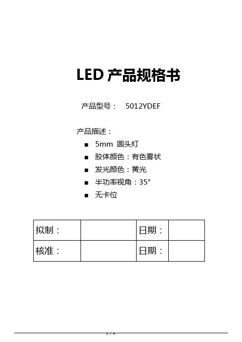
LED产品规格书产品型号:5012YDEF产品描述:■5mm 圆头灯■胶体颜色:有色雾状■发光颜色:黄光■半功率视角:35°■无卡位外形图:备注:1.所有尺寸单位为mm,如无特殊标明误差范围为±0.25mm。
2.胶体沿支架延伸不超过1.5mm。
3.多胶不超过0.5mm。
最大限度性能参数(Ta=25℃)产品光电特性(Ta=25℃)备注:1.发光强度的测量公差为±15%2.电压的测量公差为±0.05V3.主波长测量公差为±1nm使用说明1.LED贮存条件:温度10℃~26℃,湿度40%~65%,包装袋密封保存。
2.接触LED检查时需戴手套或手指套,工作台面也要接地,包装袋开口后及时封口,防止脚位氧化。
3.插件,这一过程主要是静电的防护:A:生产前检点机台设备接地线是否正常。
B:检查人员静电环是否正常,查静电环的金属是否与人的皮肤接触紧密。
C:在插件时最好要求作业员戴好静电手套或静电手指套。
D:作业台面要求铺好静电胶布,胶布之间应互相连接接地。
E:开封后,最好在24小时内用完,否则可能会引起灯脚氧化生锈。
4.焊接两只脚LED有四种方法:手动焊接,自动点焊,过锡炉焊接,波峰炉焊接:A:手动焊接:一般电铬铁温度设定在315℃左右,焊接时间不超过5秒,最好在3秒,焊接次数不要超过三次。
电铬铁温度选择一般是根据锡丝成份而定,并不是不变的。
B:自动点焊:此焊锡一般按常规设定,焊锡温度一般按锡丝成份而设定。
设定时间为3秒。
C:锡炉焊接:现阶段在中国比较普遍,在使用前一般要点检锡炉温度是否符合所设定的温度最高不超过235℃±5℃,浸锡时间不超过5秒,点检锡液温度,选择合适的助焊剂,要经常清洁锡液面。
D:波峰焊接:是目前比较先进焊接,这个对选用助焊剂比较重要,不同型号的助焊剂,对焊点光洁度不同,预热时间长短对焊接品质也有关系,经常点检锡面,锡液要定时更换,温度要根据锡条的成份调节,但最高不要超过260℃±5℃,最长时间不要超过5秒。
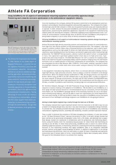
BGA-CSP Systems are cutting-edge surface mount equip-SolidWorks EuropePhone: +33-(0)4-42-15-03-85Email:*************************Corporate HeadquartersDassault Systèmes SolidWorks Corporation 300 Baker AvenueConcord, MA 01742 USA Phone: +1-978-371-5011Email:*******************Japan Headquarters SolidWorks JapanTekko Building No. 1, 3F1-8-2 Marunouchi Chiyoda-Ku,Tokyo 100-0005 Japan Phone : +81-3-6270-8700Email:******************.jphttp://www.athlete-fa.co.jp/Gaining a competitive edge through tolerance optimization and verification using TolAnalyst The managing director of Planer Ltd., Mr. Hiroshi Kuriyama, worked for 25 years in design and development at Seiko Epson Inc. before establishing Planer in 2001. Mr . Kuriyama is currently a visiting professor at Nagano Technical College and a part-time lecturer in engineering at Shin-shu University. A keen supporter of Athlete FA’s enterprises, Mr . Kuriyama explains the relevance of tolerance analysis in the design process:“For the majority of manufactured goods, it is only after the design specifications and costing of the finished article have been decided - that is, only after the end goal is determined - that the creation of detailed designs begins. As products become increasingly miniaturised and multi-functional, so the demands placed on each of their individual components continually increase. If tolerance settings are tight, there is a corresponding jump in costs and it becomes difficult to meet delivery deadlines. So, in order to reach the end goal, that is the finished product, it is essential to achieve a balance through optimal tolerance design. Of course, without tolerance design it is impossible to maintain the quality of the end product.”In the past, tolerance design was considered to be tacit knowledge in the manufacturing indus-try, and as such was communicated from designer to designer on the job. However, due to a generational change in engineers and developments in the design environment, recently this method of knowledge transfer has become increasingly difficult. There are now overwhelming numbers of young designers across all sectors of the industry who do not know tolerance design theory. So, in collaboration with Planer, Athlete FA provided not only introductory and intermedi-ate SolidWorks seminars for their design engineers but also training for all employees in the basic principles of tolerance design.Having implemented the SolidWorks tolerance analysis tool, TolAnalyst, innovative activities such as comparing and verifying the results of manually calculated analysis are being tested. Through such activities the company aims to utilize the SolidWorks design tools to maximum effect.The Challenge: Athlete FA provided a 2-day lecture course in the fundamentals of tolerance design to all employees, including design engineers. Successful tolerance design has significant impact on cost, quality and time to market. Therefore, in addition to becoming profi-cient in using SolidWorks, design engi-neers need to be able to design product functionality itself that incorporates assembly and tolerance. A pioneering example in the equipment manufacturing industry, Athlete FA is proactively verify-ing the analytical results of tolerance optimization obtained by manual calcula-tion and those obtained using the Solid-Works TolAnalyst.The Solution: In the design section at Athlete FA there is one SolidWorks seat per engineer. Thanks to a comprehensive training program for all employees and the creation of a standard operation manual covering features, modelling and assembly, the skill level of all engineers is consistent. To make full use of the benefits of a transition to 3D, a set of standard design guidelines was estab-lished on the basis of detailed consulta-tions at the time of introducing Solid-Works. All Athlete FA products are now designed using SolidWorks.A 3D model of the Micro Ball Mounter BM-1100W created in SolidWorksA drawing of th e main unit of th e CSP-capable BGA Ball Mounting System BA-1500PP sketched by Athlete FA design engineers (to give a simple example). There are 39 tolerance factors in total, 19 dimensional and 20 geometrical tolerance factors. Using tolerance design th e possibilities for optimizing tolerance distribution (cost reduction) and eliminating th e need to readjust tolerance have widened.Analytical results produced by TolAnalyst (first section only shown here). Calculating tolerance in mainly height directions would take approximately half a day to calculate manually but is completed in around 20-30 minutes with TolAnalyst.Athlete FA CorporationHeadquarters: 2970-1 Shiga, Suwa City, Nagano, JapanEstablished: March 1, 1988Business outline: Factory Automation Engineering- Development, design and marketing of a range of high-precision mount-ing and assembly systems for vari-ous industrial applications including office automation equipment, semi-conductors, electronic components, automobiles, and communications devices.- Design, manufacture and marketing of automation equipment.。
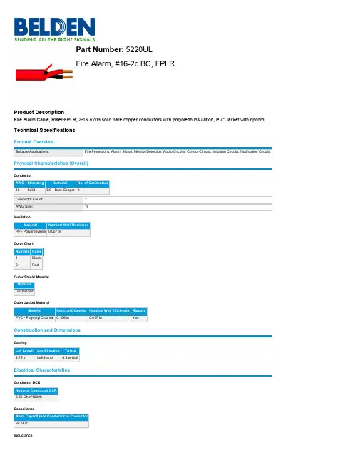
Part Number:Fire Alarm, #16-2c BC, FPLRProduct DescriptionFire Alarm Cable, Riser-FPLR, 2-16 AWG solid bare copper conductors with polyolefin insulation, PVC jacket with ripcord Technical SpecificationsProduct OverviewSuitable Applications:Physical Characteristics (Overall)ConductorAWG Stranding Material16Solid BC - Bare CopperConductor Count:AWG Size:Nominal Inductance0.145 µH/ftCurrentElement Max. Recommended Current [A]10C Temperature Rise Per conductor @ 25°C: 6.3 AVoltageUL Voltage Rating300V RMSTemperature RangeUL Temp Rating:75°COperating Temp Range:-20°C To +75°C Mechanical CharacteristicsBulk Cable Weight:21 lbs/1000ftMax Recommended Pulling Tension:62.4 lbsMin Bend Radius/Minor Axis: 1.625 inStandardsNEC Articles:760NEC/(UL) Specification:FPLRCPR Euroclass:EcaApplicable Environmental and Other ProgramsEU Directive 2000/53/EC (ELV):YesEU Directive 2003/96/EC (BFR):YesEU Directive 2011/65/EU (ROHS II):YesEU Directive 2012/19/EU (WEEE):YesEU Directive 2015/863/EU:YesEU Directive Compliance:EU Directive 2003/11/EC (BFR) EU CE Mark:YesEU RoHS Compliance Date (yyyy-mm-dd):2005-04-01CA Prop 65 (CJ for Wire & Cable):YesMII Order #39 (China RoHS):YesSuitabilitySuitability - Indoor:YesFlammability, LS0H, Toxicity TestingUL Flammability:UL1666 RiserCSA Flammability:FT4Part NumberPlenum (Y/N):NPlenum Number:6220ULVariantsItem #Color Footnote5220UL 0101000BLACK5220UL D151000BLUE5220UL 0011000BROWN5220UL 0031000ORANGE C5220UL 0021000RED C5220UL 002500RED5220UL 002U1000RED5220UL 002A1000RED5220UL 009U1000WHITE5220UL 0041000YELLOWFootnote: C - CRATE REEL PUT-UP.© 2018 Belden, IncAll Rights Reserved.Although Belden makes every reasonable effort to ensure their accuracy at the time of this publication, information and specifications described here in are subject to error or omission and to change without notice, and the listing of such information and specifications does not ensure product availability.Belden provides the information and specifications herein on an "ASIS" basis, with no representations or warranties, whether express, statutory or implied. In no event will Belden be liable for any damages (including consequential, indirect, incidental, special, punitive, or exemplary damages) whatsoever, even if Belden has been advised of the possibility of such damages, whether in an action under contract, negligence or any other theory, arising out of or in connection with the use, or inability to use, the information or specifications described herein.All sales of Belden products are subject to Belden's standard terms and conditions of sale.Belden believes this product to be in compliance with EU RoHS(Directive 2002/95/EC, 27-Jan-2003). Material manufactured prior to the compliance date may be instock at Belden facilities and in our Distributor's inventory. The information provided in this Product Disclosure, and the identification of materials listed as reportable or restricted within the Product Disclosure, is correct to the best of Belden's knowledge, information, and belief at the date of its publication. The information provided in this Product Disclosure is designed only as a general guide for the safe handling, storage, and any other operation of the product itself or the one that it becomes a part of. This Product Disclosure is not to be considered a warranty or quality specification. Regulatory information is for guidance purposes only. Product users are responsible for determining the applicability of legislation and regulations based on their individual usage of the product.Belden declares this product to be in compliance with EU LVD (Low Voltage Directive 73/23/EEC), as amended by directive 93/68/EEC.。

and reliability.如产品需要用在有特殊质量要求及可靠性要求的地方,请提前咨询瑞丰的销售人员以取得相关信息。
disassemble and analyzein written form.在取得瑞丰的同意前,客户不应该对产品进行拆解分析,如发现失效产品,请直接书面通知瑞丰。
RF-BNB190TS-CFFeatures 特征Extremely wide viewing angle.发光角度大Suitable for all SMT assembly and solder process.适用于所有的SMT组装和焊接工艺 Moisture sensitivity level:Level3.防潮等级Level3Package:4000pcs/reel.包装每卷4000pcsRoHS compliant.满足RoHS要求Description描述The Colour LED which was fabricated by using a blue chip该产品为蓝光LED,是由蓝光芯片封装形成Applications应用Optical indicator.光学指示Switch and Symbol,Display.开关和标识、显示器等General use.其他应用Package Dimension 外观尺寸NOTES:1.All dimensions units are millimeters.(所有尺寸标注单位为毫米)2.All dimensions tolerances are 0.2mm unless otherwise noted.(除特别标注外,所有尺寸公差为±0.2毫米)Electrical/Optical Characteristics at Ts=25°C电性与光学特性----450 Note:备注Vr=5V For test conditions.Vr=5v为测试分选条件。
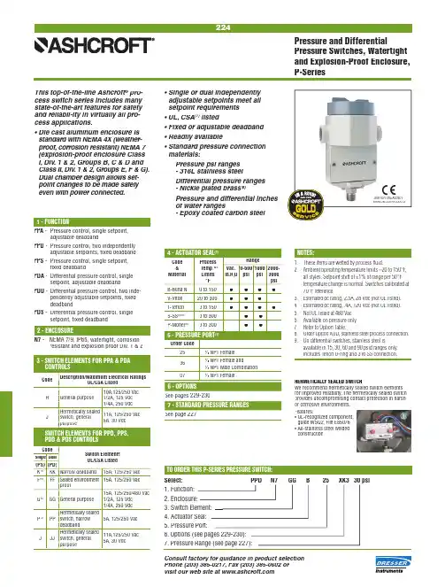
224Consult factory for guidance in product selection Phone (203) 385-0217, Fax (203) 385-0602 or visit our web site at Process Code R ange & Temp.(2) Vac. 0-600 1000 2000- Material Limits in.H 2O psi psi 3000 °F psi B-Buna N 0 to 150 ● ● ● ●V-Viton 20 to 300 ● ● ●T-Tefl on 0 to 150● ● ● ●S-SS (6)(9)0 to 300 ● ● P -Monel (6)0 to 300 ● ●D escription/Maximum Electrical Ratings Code UL/CSA Listed10A,125/250 VacH General purpose 1/2A, 125 Vdc 1/4A, 250 VdcHermetically sealed J switch, general 11A, 125/250 Vac purpose5A, 30 VdcCodeSwitch ElementsSingle D ual UL/CSA Listed(PS) (PD) K (4) KK Narrow deadband 15A, 125/250 Vac F (4)FF Sealed environment 15A, 125/250 Vacproof15A, 125/250/480 VacG (5) GG General purpose 1/2A, 125 Vdc 1/4A, 250 VdcHermetically sealedP (3) PP switch, narrow 5A, 125/250 VacdeadbandHermetically sealedJ JJ switch, general 11A,125/250 Vacpurpose 5A, 30 Vdc Select: PPD N7 GG B 25 XK3 30 psi 1. Function: 2. Enclosure: 4. Actuator Seal: 5. Pressure Port: 6. Options (see pages 229-230): 7. Pressure Range (see page 227):Pressure and Differential Pressure Switches, Watertight and Explosion-Proof Enclosure, P-Series • S ingle or dual independently adjustable setpoints meet all setpoint requirements • U L, CSA listed lis (7)• Fixed or adjustable deadband • Readily available • S tandard pressure connection materials:Pressure psi ranges - 316L stainless steel Differential pressure ranges - Nickle plated brass (8)Pressure and differential inches of water ranges - Epoxy coated carbon steel This top-of-the-line Ashcroft oft pro- pr ®cess switch series includes many state-of-the-art features for safety and reliabil-ity in virtually all pro-cess applications.• D ie cast aluminum enclosure is standard with NEMA 4X (weather-proof, corrosion resistant) NEMA 7 (explosion-proof enclosure Class I, Div. 1 & 2, Groups B, C & D and Class II, Div. 1 & 2, Groups E, F & G). Dual chamber design allows set-point changes to be made safely even with power connected.PPA - Pressure control, single setpoint, adjustable deadband PPD - Pressure control, two independently adjustable setpoints, fi xed deadband PPS - Pressure control, single setpoint, fi xed deadband PDA - Differential pressure control, single setpoint, adjustable deadbandPDD - Differential pressure control, two inde- pendently adjustable setpoints, fi xed deadband PDS - Differential pressure control, single setpoint, fi xed deadbandN7 - N EMA 7/9, IP65, watertight, corrosionresistant and explosion proof Div. 1 & 2 See pages 229-230 See page 227 Order Code 25 14⁄ NPT Female 1⁄4 NPT Female and 06 12⁄ NPT Male Combination 07 12⁄ NPT Female 3. Switch Element: HERMETICALLY SEALED SWITCH We recommend hermetically sealed switch elements for improved reliability. The hermetically sealed switch provides uncompromising contact protection in harsh or corrosive environments. Features:• U L-recognized component, guide WSQ2, File E85076• A ll-stainless steel welded construction LOOK FOR THIS AGENCY MARK ON OUR PRODUCTS 1. These items are wetted by process fl uid.2. A mbient operating temperature limits –20 to 150°F , all styles. Setpoint shift of ±1% of range per 50°F temperature change is normal. Switches calibrated at 70°F reference.3. Estimated dc rating, 2.5A, 28 Vdc (not UL listed).4. Estimated dc rating, .4A, 120 Vdc (not UL listed).5. Not UL listed at 480 Vac.6. Available on pressure only.7. Refer to Option Table.8. O rder Option XUD, stainless steel process connection.9. On differential switches, stainless steel is available in 15, 30, 60 and 90 psid ranges only. Includes Tefl on O-ring and 316 SS connection.。
Ra-01S规格书版本V1.1版权©2020免责申明和版权公告本文中的信息,包括供参考的URL地址,如有变更,恕不另行通知。
文档“按现状”提供,不负任何担保责任,包括对适销性、适用于特定用途或非侵权性的任何担保,和任何提案、规格或样品在他处提到的任何担保。
本文档不负任何责任,包括使用本文档内信息产生的侵犯任何专利权行为的责任。
本文档在此未以禁止反言或其他方式授予任何知识产权使用许可,不管是明示许可还是暗示许可。
文中所得测试数据均为安信可实验室测试所得,实际结果可能略有差异。
文中提到的所有商标名称、商标和注册商标均属其各自所有者的财产,特此声明。
最终解释权归深圳市安信可科技有限公司所有。
注意由于产品版本升级或其他原因,本手册内容有可能变更。
深圳市安信可科技有限公司保留在没有任何通知或者提示的情况下对本手册的内容进行修改的权利。
本手册仅作为使用指导,深圳市安信可科技有限公司尽全力在本手册中提供准确的信息,但是深圳市安信可科技有限公司并不确保手册内容完全没有错误,本手册中的所有陈述、信息和建议也不构成任何明示或暗示的担保。
文件制定/修订/废止履历表版本日期制定/修订内容制定核准V1.02020.8.12首版徐V1.12020.8.19更新部分参数徐目录一、产品概述 (5)二、电气参数 (6)三、外观尺寸 (8)四、管脚定义 (10)五、原理图 (11)六、设计指导 (12)七、回流焊曲线图 (14)八、包装信息 (15)九、联系我们 (15)一、产品概述安信可LoRa系列模块(Ra-01S)由安信可科技设计开发。
该模组用于超长距离扩频通信,其射频芯片SX1268主要采用LoRa™远程调制解调器,用于超长距离扩频通信,抗干扰性强,能够最大限度降低电流消耗。
借助SEMTECH的LoRa™专利调制技术,SX1268具有超过-148dBm的高灵敏度,+22dBm的功率输出,传输距离远,可靠性高。
同时,相对传统调制技术,LoRa™调制技术在抗阻塞和选择方面也具有明显优势,解决了传统设计方案无法同时兼顾距离、抗干扰和功耗的问题。
目录1.产品概述 (2)2.主要特性 (2)3.系统框图 (2)4.封装及引脚说明 (3)5.功能描述 (5)5.1输出模式和选项脚位 (5)5.2按键最长输出时间 (5)5.3低功耗模式 (5)5.4灵敏度调整 (5)6.应用电路 (6)7.电气特性 (7)7.1电气特性极限参数 (7)7.2直流特性 (7)8.封装信息 (8)8.1SOT23-6封装 (8)8.2DFN2x2-6L封装尺寸 (9)8.3DFN2x2-6L编带信息 (10)8.4DFN1x1-4L封装尺寸 (11)8.5DFN1x1-4L编带信息 (12)9.历史记录 (12)单触控单输出IC文件编号:PT-DS210071.产品概述PT2041A是一款单通道触摸检测芯片。
该芯片内建稳压电路,提供稳定电压给触摸感应电路使用,同时内部集成高效完善的触摸检测算法,使得芯片具有稳定的触摸检测效果。
该芯片专为取代传统按键而设计,具有宽工作电压与低功耗的特性,可广泛地满足不同消费类应用的需求。
2.主要特性⚫工作电压范围:2.4~5.5V⚫工作温度范围:-40~85℃⚫抗干扰性能优良:内置稳压电路、上电复位、低压复位功能及环境自适应算法等多种措施⚫待机工作电流:典型值2uA@V DD=3V/无负载⚫按键最长响应时间:低功耗模式下约200ms@V DD=3V⚫可接外部电容(1~50pF)调整触摸灵敏度⚫输出模式选择(TOG):同步输出或锁存(toggle)输出⚫CMOS输出(QC)有效电平选择(AHLB):高电平或低电平输出有效⚫按键最长输出时间:16秒(±30%)⚫上电约0.4秒的初始化时间,此期间内不要触摸检测点,且此时所有功能被禁止⚫HBM ESD:大于2KV⚫封装形式:SOT23-6、DFN2*2-6L、DFN1*1-4L3.系统框图传感器震荡电路时序计算器 &功能选项控制电路系统振荡电路传感器 &参考检测电路触摸检测电路输出&驱动电路TCHQCTOGAHLB图1 系统框图4.封装及引脚说明QC VSS TCHTOGVDDAHLB 34 PT2041AT6图2 PT2041A SOT23-6管脚示意图TCH VSS QCAHLBVDDTOG65423PT2041AD6 1图3 PT2041A DFN2x2-6L管脚示意图注:引脚布局与SOT23-6反向VDD TCHQCVSS43 2PT2041AD41图4 PT2041A DFN1x1-4L封装管脚示意图注:固定为同步输出模式,输出高电平有效表1引脚说明表223VSS P地312TCH I触摸感应输入46/AHLB I-PL 输出高电平有效或低电平有效选择0(默认值):高电平有效;1:低电平有效551VDD P电源64/TOG I-PL 输出模式选择0(默认值):同步输出;1:锁存(toggle)输出引脚类型:I:CMOS输入O:CMOS输出I/O:CMOS输入/输出P:电源/接地I-PH:CMOS输入内置上拉电阻I-PL:CMOS输入内置下拉电阻5.功能描述5.1 输出模式和选项脚位AHLB 和TOG 选项脚位为锁存类型:上电默认状态为0,若上电前管脚被接至VDD ,则上电后状态变为1,且不会有电流漏电。
HN-1206 SPEC V1.0规格书SpecificationHN-1206-9.0品名Model namePROPRIETARYHuaneng Electronic co.,Ltd.CONFIDENTIALHuaneng Electronic co.,Ltd.Version #Spec V1.0制作日期Date2018/03/12准备PreparedYang shu yin Acoustic specialist,R&D Dept.审核ApprovedZhang chang hua Executive Manager,R&D Dept.江苏华能电子有限公司Components Operating Div. HuanengElectronic co.,Ltd.规 格 书 号 SPECIFICATION NO.:PECIFICATION FORAPPROV AL规 格 承 认 书客户承认CUSTOMER CONFIRM AND SIGN检查TESTED BY审核CHECKED BY承认APPROVED BY江苏华能电子有限公司JIANGSU HUANENG ELECTRONICS CO.,LTD.制作ISSUED BY审查CHECKED BY确认APPROVED BY客 户CUSTOMER :有限公司项 目ITEM : 电磁无源一体正发声蜂鸣器(外部驱动)型 号TYPE : HN-1206描述DESCRIPTION : φ12.0 x H 9.0mm 5Vo-p 42Ω 2000Hz ≥85dB版 本EDITION NO. : V1.2日 期DATE : 2018/10/04客户料号CUSTOMER NO.:1.适用范围:本规范适用于HN-1206 蜂鸣器。
HN-1206 SPEC V1.0 This specifications apply the HN-1206 buzzer.2.基本规格/General specification项目/Item规格/Spec条件/Condition1额定电压Rated voltage5V2工作电压Operation voltage3~7V3声压Sound Pressure Level=SPL Min 85dB 测试环境:标准状态,标准驱动电路,额定电压测试距离:0.1mStandard State,Standard Drive Circuit. Rated voltage,Distance at 0.1m4平均消费电流Average consumption current Max 50mA5振荡频率Oscillation frequency2000Hz6响应时间Response time Max 50mS最低工作电压Lowest operation voltage7工作温度范围Range of operation temperature-20~+75℃声压 ≥85dB SPL ≥85dB8保存温度范围Range of preservation temperature-30~+85℃9线圈电阻Coilresistance 42± 3 Ω拉负荷方向的终端轴Pull load on the direction of the terminalaxis10外部尺寸Externals sizeΦ12x9.0参阅附图Refer to the attached drawing11重量Mass2g☆标准状态:常温(15~35℃),湿度(25~85%相对湿度),空气压力(860~1060hpa)在假设的情况判断,测试是-基本状态下进行。
With increasing demands for high-current interconnections for applications such as fast charging, high-resolution/backlit displays, and LED lighting, Molex offers fine-pitch connectors for ultra-compact board-to-board connections. This document highlights 0.35 and 0.40mm pitch SlimStack board-to-board connectors with 6 to 60 pin counts and from 6.0 to over 15.0A current ratings per connectorMarkets and ApplicationsFeatures and AdvantagesWearables Fast ChargingConsumerSmall Displays and LED LightingsDatacomMobilesHigh Power Fine-PitchBoard-to-Board ConnectorsEach of these Molex SlimStack board-to-boardconnectors has a receptacle and a plug, utilizeshigh-current terminal systems, and incorporatesone or more of the following features, offeringgreat advantages to system designersArmor’ Nails at the end caps: For robustnessand high-current terminalsFull armor design protects the housing from insideand outside, preventing connector damage due tomisalignment.These power nails can conduct up to 5.0A(per nail) for high power transfer.Stadium Structure: For aneasy-to-find mating positionThe center of the housingis lower, making the matingposition easier to findRobust dual contact terminals: Forexcellent insertion/retention force anda clear click feeling upon matingThe terminal shape makes it easy to leadthe connector with reduced insertionforce, while the lock shape provides aclick feeling to ensure complete matingto the operatorsSharp and big drop atproper mating position©2020 MolexOrder No. 987652-3081USA/0k/GF/2020.12 /link/slimstack.htmlMolex is a registered trademark of Molex, LLC in the United States of America and may be registered in other countries; all other trademarks listed herein belong to their respective owners.SlimStack Fine Pitch Connectors with Power Nails* TP = (circuit/2-1) x pitch** Please refer to Guide for Hardware Interface Standard on 。
文
文件编号
QA-WI-K079 件 制订日期 2004-6-9 名 版 次 A TOR C H 火炬 称
无铅排列晶片电阻规格标准 书页 次 共16页 第3页 四、尺寸:( )
R C A02-2D/RTA03-2D/RTA03-2C R C A02-4D/RCA03-4D
R C A02-4C/RTA03-4C
R C A02-8D/RTA03-8C
Circuits Circuits
2 Circuits L 1 L 1
称 页 次 共16页 第7页
Specifications 规格 TEM
项目
Conditions 条件 Resistors Jumper
◎测试方法三(电烙铁试验):
加热温度:350±10℃
电烙铁加热时间:3+1/-0sec.
取电铬铁加热于电极两端后,取出静置60分钟以上,再量测
阻值变化率。
依据SONY (SS-00254-5)
依据JIS-C5202-6.10
步骤 制程名称 试验环境条件
1 阻值量测 室温
2 烘干 125℃、24小时
3 湿润 85℃、85%RH 、168小时
4 焊锡炉测试
260±3℃、10秒 5 静置 室温
6 焊锡炉测试
260±3℃、10秒 7 阻值量测 室温
Solderability 焊锡性 前处理
将晶片电阻放置于PCT 试验机内,在温度105℃、湿度100%
及气压1.22×10⁵ pa 的饱和条件下进行4小时的老化测试,取
出后静置于室温下2小时。
测试方法
◎测试项目一(焊锡炉测试):
将电阻浸于245±3℃之炉中3+1/-0秒后取出置于显微镜下观
察焊锡面积。
◎测试项目二(小球平衡法):
将浸渍助焊剂后的电阻置放于Wetting Balance 测试机,依下
列条件做设定,并记录晶片电阻焊锡润湿时间。
焊锡槽平衡法测试条件
条件
焊锡温度 245±3℃
浸渍速度 1~5mm/S
浸渍高度 0.10mm
浸渍角度 水平
25mg →0402、0603 锡球重量 200mg →0805、1206、1210、2010、2512
依据SONY (SS-00254-2)
依据JIS-C5202-6.11
1.试验项目一: 导体吃锡面积应大于95%。
2.试验项目二: Zero Cross Time 在3秒内完成。
文件编号 QA-WI-K079
制订日期 2004-6-9
版次 A TORCH
火炬
文
件
名
称
无铅排列晶片电阻器规格标准
书
页次共16页第8页
Specifications规格TEM
项目
Conditions
条件Resistors Jumper
Joint
strength of
solder
焊锡粘合
强度
前处理
将晶片电阻放置于PCT试验机内,在温度105℃、湿度100%
及气压1.22×10⁵ Pa的饱和条件下进行4小时的老化测试,
取出后静置于室温下2小时。
测试项目 (弯折性测试):
将晶片电阻焊于折性测试板中,置于弯折测试机上,在测
试板中央施力下压,于负荷下量测阻值变化率。
下压深度(D):R T T02、03、05=5mm
RTT06、12=3mm
RTT20、25=2mm
◎测试项目 (耐久性测试):
取测试一及测度二的产品经Table 1条件之温度循环试验
后,再于相同测试项目下量测阻值变化率,并计算前后变
化率的误差。
此试验是在温度循环测试时测量阻值变化率,故应该在循
环测试到250±4次、500±4次、1000±4次时,分别量测。
Table 1温度循环测试条件
测试条件
最低温度 -35±5℃
最高温度 105±5℃
温度保留时间 15分钟
依据SONY(SS-00254-7)
依据JIS-C5202.1.4
试验项目 :
(一)阻值变化率
△R%=±(1.0%+0.05Ω)
(二)外观无损伤、无侧导脱落及本
体断裂发生。
试验项目 :
温度循环前后固著性及弯折性测试
其阻值变化率的误差在50%以下。
50mΩ
Lower
Leaching
试验
将晶片电阻浸于助焊剂中,再将晶片电阻完全浸置于焊锡
槽内,温度设定260±5℃、时间30+1/-0秒,取出后洗净。
置于显微镜下观察焊锡面积。
依据SONY(SS-00254-9)
1.导体吃锡面积应大于95%。
2.在电极边线处不应见到下层的物质(例如白基
板)。
称 页 次 共16页 第9页
5.3环境试验(Environmental Test ) Specifications 规格
ITEM 项目 Conditions 条件
Resistors Jumper 0.5%、1%:±(1.0%+0.05Ω) 2%、5%:±(2.0%+0.10Ω) 50m Ω Lower Resistance to
Dry Heat
耐热性试验
置于125±5℃之烤箱中96±4hr ,取出静置1hr 以上再量测阻值变化率。
依据JIS-C5202-7.2 外观无损伤,无短路及烧毁现象。
±(1.0%+0.05Ω) 50m Ω Lower Temperature
Cycling
温度环境 将排列晶片电阻置入温度循环中,温度为-55℃ 30分钟,室温3分钟,+125℃ 30分钟,室温3分钟为一循环,共计循环5次后取出,静置60分钟再量测阻值变化率。
Step
Temperature (℃)Time (minute )1
-55±5 30 2
25±5 3 3
125±5 30 4 25±5 3 依据JIS-C5202-7.4 外观无损伤,无短路及烧毁现象。
0.5%、1%:±(2.0%+0.05Ω) 2%、5%:±(3.0%+0.05Ω) 50m Ω Lower Loading Life
in Moisture
耐湿负荷 置於温度40±2℃相对湿度90~95%恒温恒湿槽中,并施加额定电压,90分钟ON ,30分钟OFF ,共1,000hrs 取出静置60分钟以上再量测阻值变化率。
依据JIS-C5202-7.9 外观无损伤,无短路及烧毁现象。
0.5%、1%:±(2.0%+0.05Ω) 2%、5%:±(3.0%+0.10Ω)
50m Ω Lower Load Life
负荷寿命 浸於70±2℃之烤箱中施加额定电压,90分钟ON ,30分钟OFF ,共1,000hrs 取出静置60分钟以上再量测阻值变化率。
依据JIS-C5202-7.10 外观无损伤,无短路及烧毁现象。
Whisker 试验
晶片电阻可化分为下面二种测试: ◎测试项目一(温度循环测试):
将晶片电阻置放于温度循环试验箱内,并依下列条件做测试,
试验后置于室温下2小时。
Table1温度循环测试条件
最低储存温度 -35±5℃
最高储存温度 125±5℃
温度保留时间 7分
温度循环次数 500±4
◎测试项目二(耐湿性测试):
将晶片电阻置放于恒温恒湿箱内,并依下列条件做测试,试
验后置于室温下2小时。
Table2不变的温度与湿度的测试条件
温度 85℃
湿度
85%RH 测试时间 500±4小时
◎检查
将放大镜的倍数调至40或大于40的倍数下做视察和测试,
如果此方法难做出判断,我们可以改用扫描电子显微镜
(SEM ),且将倍数调至1000或大于1000倍数下做视察和测
试。
依据SONY (SS-00259-8)
Whisker 长度在50μm 之内。
R C A02-4D R C A02-4C R C A03-4D R C A03-4C R C A02-8D R C A03-2D R C A03-8C R C A03-2C
≥190mm(前导带)
≥95mm(后导带)晶片电阻器引带
10.4 上胶带剥离力量(Peel off Strength):≥450mm
TOR C H
福建火炬电子科技股份有限公司
文件修订记录表
文件名称无铅排列晶片电阻器规格标准书编号 QA-WI-K079
管制章
制订日期修订
页次
修订内容修订者备注
2004-6-9 全新制订。
曾小力
版次:A QA-QR-K027。