PT4121规格书
- 格式:pdf
- 大小:618.12 KB
- 文档页数:11
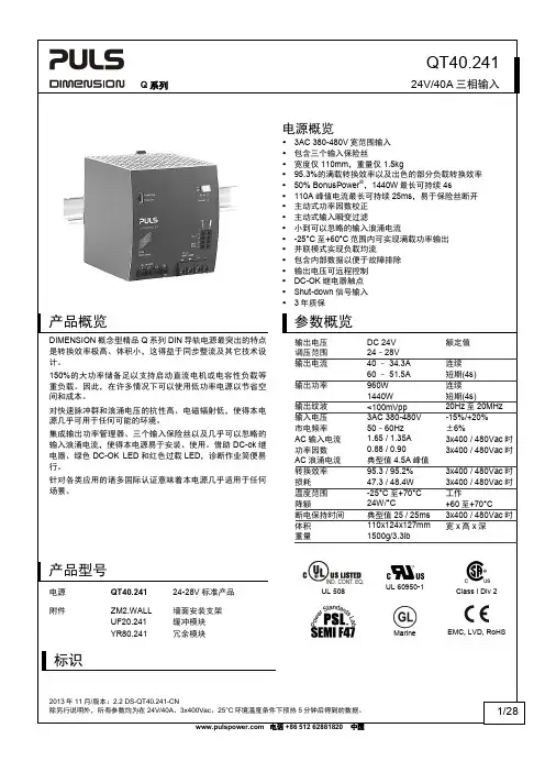
产品概览DIMENSION概念型精品Q系列DIN导轨电源最突出的特点是转换效率极高、体积小,这得益于同步整流及其它技术设计。
150%的大功率储备足以支持启动直流电机或电容性负载等重负载。
因此,在许多情况下可以使用低功率电源以节省空间和成本。
对快速脉冲群和浪涌电压的抗性高、电磁辐射低,使得本电源几乎可用于任何可能的环境。
UL 60950-1Class I Div 2Marine EMC, LVD, RoHS输入输出输入电流2A/DIV3x400Vac 24Vdc100ms/DIVQ 系列24V/40A 三相输入7. 断电保持时间3AC 400V *)3AC 480V *)断电保持时间 典型值 50ms 50ms 24V, 20A 时,请参阅图7-1 最小值 40ms 40ms 24V, 20A 时,请参阅图7-1 典型值 25ms 25ms 24V, 40A 时,请参阅图7-1最小值20ms20ms24V, 40A 时,请参阅图7-1*)关于仅使用三相2线系统的运行曲线和数值,请参阅第25.4节图7-1 断电保持时间与输入电压图7-2 关断性能,定义01020304050ms 3203604004403x480Vac输入电压断电保持时间24V, 20A ,典型值24V, 40A ,典型值24V, 20A ,最小值24V, 40A ,最小值-5%断电保持时间输出电压输入电压L1 L2 L3Q 系列24V/40A 三相输入8. DC-OK 继电器触点此功能监控电源自身产生的输出电压。
该输出电压与电源输出并联的电源所产生的回馈电压相隔离。
触点闭合 输出电压达到设定输出电压的90%时。
触点断开 输出电压突降至设定输出电压以下10%时。
短时间突降会延长至250ms 的信号长度。
不足1ms 的突降将被忽略。
触点再次闭合 输出电压超过设定电压的90%时。
触点规格 最大值 60Vdc 0.3A, 30Vdc 1A, 30Vac 0.5A 电阻性负载 最小值5Vdc 时1mA最小容许负载隔离电压 见第21章的绝缘强度表。

产品详情电气绝缘体系烧注和涂料用树脂BECTRON PL4122-E BLF稀释剂239产品简述BECTRON PL4122 E BLF是一种透明的改性醇酸树脂胶.BECTRON PL4122E BLF 不含有任何芳香族成分。
该绝缘胶即使在环境的影响下仍具有优异的热性能的电性能。
该绝缘胶可提供以下品种:# 三种固含量/黏度可满足不同的应用:。
/37 E BLF。
/40 E BLF…../45 E BLF#不同的颜色易于质量控制:。
E BLF(无色)。
E BLF 橙色(透明)。
E BLF FLZ(带荧光)应用领域:电子涂层:1.用于汽车,船舶和航空的电路板印刷2.混合线圈3.SMD设计4.分立元件特点温度稳定性温度指数 134。
C安全性BECTRON PL4122 E BLF系列产品(Under writes L aboratories)是按照E 211569的要求而准备的。
介电强度高体积电阻率(包括在潮湿状态下)成膜厚度在非常薄的条件下仍具有良好的电性能。
环境影响BECTRON PL4122E BLF可最大限度的保护部件免受机械应力、污染物、潮气、灰尘和腐蚀性气体的破坏。
耐化学性对潮气,弱酸和碱及易在汽车和船舶工业中使用的各种烷烃和不同的油均有良好的抵抗力。
固化工艺:气干23℃,16小时加速固化80℃,0.5小时附着力在-40℃/+130℃温度变化下对印刷电路板仍具有极高的粘结力。
应用工艺BECTRON PL4122 E BLF 可适合喷涂,浸渍,和刷涂工艺。
喷涂工艺推荐的黏度是60秒,4#杯测。
(DIN/EN/ISO 2431)。

IPC-4121Guidelines for Selecting Core Constructions for Multilayer Printed Wiring Board ApplicationsASSOCIATION CONNECTING ELECTRONICS INDUSTRIESANSI/IPC-4121January 2000A standard developed by IPCThe Principles of Standardization In May1995the IPC’s Technical Activities Executive Committee adopted Principles of Standardization as a guiding principle of IPC’s standardization efforts.Standards Should:•Show relationship to Design for Manufacturability(DFM)and Design for the Environment(DFE)•Minimize time to market•Contain simple(simplified)language•Just include spec information•Focus on end product performance•Include a feedback system on use andproblems for future improvementStandards Should Not:•Inhibit innovation•Increase time-to-market•Keep people out•Increase cycle time•Tell you how to make something•Contain anything that cannotbe defended with dataNotice IPC Standards and Publications are designed to serve the public interest through eliminating misunderstandings between manufacturers and purchasers,facilitating interchangeability andimprovement of products,and assisting the purchaser in selecting and obtaining with minimumdelay the proper product for his particular need.Existence of such Standards and Publicationsshall not in any respect preclude any member or nonmember of IPC from manufacturing or sell-ing products not conforming to such Standards and Publication,nor shall the existence of suchStandards and Publications preclude their voluntary use by those other than IPC members,whether the standard is to be used either domestically or internationally.Recommended Standards and Publications are adopted by IPC without regard to whether theiradoption may involve patents on articles,materials,or processes.By such action,IPC doesnot assume any liability to any patent owner,nor do they assume any obligation whatever toparties adopting the Recommended Standard or ers are also wholly responsiblefor protecting themselves against all claims of liabilities for patent infringement.IPC Position Statement on Specification Revision Change It is the position of IPC’s Technical Activities Executive Committee(TAEC)that the use and implementation of IPC publications is voluntary and is part of a relationship entered into by customer and supplier.When an IPC standard/guideline is updated and a new revision is pub-lished,it is the opinion of the TAEC that the use of the new revision as part of an existing relationship is not automatic unless required by the contract.The TAEC recommends the use of the lastest revision.Adopted October6.1998Why is there a charge for this standard?Your purchase of this document contributes to the ongoing development of new and updated industry standards.Standards allow manufacturers,customers,and suppliers to understand one another better.Standards allow manufacturers greater efficiencies when they can set up their processes to meet industry standards,allowing them to offer their customers lower costs.IPC spends hundreds of thousands of dollars annually to support IPC’s volunteers in the standards development process.There are many rounds of drafts sent out for review andthe committees spend hundreds of hours in review and development.IPC’s staff attends and participates in committee activities,typesets and circulates document drafts,and follows all necessary procedures to qualify for ANSI approval.IPC’s membership dues have been kept low in order to allow as many companies as possible to participate.Therefore,the standards revenue is necessary to complement dues revenue.The price schedule offers a50%discount to IPC members.If your company buys IPC standards, why not take advantage of this and the many other benefits of IPC membership as well?For more information on membership in IPC,please visit or call847/790-5372. Thank you for your continued support.©Copyright2000.IPC,Northbrook,Illinois.All rights reserved under both international and Pan-American copyright conventions.Any copying,scanning or other reproduction of these materials without the prior written consent of the copyright holder is strictly prohibited and constitutes infringement under the Copyright Law of the United States.ANSI/IPC-4121ASSOCIATION CONNECTINGELECTRONICS INDUSTRIESGuidelines for SelectingCore Constructionsfor Multilayer PrintedWiring Board ApplicationsDeveloped by the Design Guidelines for MLB Materials Task Group(3-11c)of the Base Materials Committee(3-10)of IPCAPPROVED DECEMBER 8, 1999 BYAMERICAN NATIONAL STANDARDS INSTITUTEUsers of this standard are encouraged to participate in thedevelopment of future revisions.Contact:IPC2215Sanders RoadNorthbrook,Illinois60062-6135Tel847509.9700Fax847509.9798AcknowledgmentAny Standard involving a complex technology draws material from a vast number of sources.While the principal members of the IPC Design Guidelines for MLB Materials Task Group(3-11c)of the Base Materials Committee(3-10)are shown below,it is not possible to include all of those who assisted in the evolution of this standard.To each of them,the mem-bers of the IPC extend their gratitude.Base Materials Committee Design Guidelines forMLB Materials Task GroupTechnical Liaisons of theIPC Board of DirectorsChairman Doug Sober isolaUSA ChairmanDoug SoberisolaUSAStan PlzakPensar Corp.Peter BigelowBeaver BrookCircuits Inc.Design Guidelines for MLB Materials Task GroupIvan E.Araktingi,Ph.D.,AlliedSignal Laminate SystemsNanci J.Baggett,Dell Computer Corp.Richard A.Barnett,Compaq Computer Corp.David B.Barr,Clark-Schwebel,Inc. Erik J.Bergum,Polyclad Laminates, Inc.Mike Bryant,BGF Industries,Inc. David J.Corbett,Defense Supply Center ColumbusNitin B.Desai,Motorola,Inc. Robert J.Dunnagan,BGF Industries, Inc.Theodore Edwards,Honeywell Inc. Air Transport Sys.Werner Engelmaier,Engelmaier Associates,L.C.Florian J.Gunkle,Jr.,AlliedSignal Laminate SystemsLaurence G.Johnson,General Electric Co.Dr.Roger A.Jones,ITRIYvonne Julian-Hargrove,DowChemical USARichard E.Kajander,Johns ManvilleBruce R.Kline,TaconicRobert J.Konsowitz,GILTechnologiesJeffrey M.Krech,Multilayer Tek,L.P.Ernest wton,Ph.D.,PPGIndustries,Inc.Edward E.Lewis,Jr.,isolaUSAP.Douglas Lyle,Advanced GlassfiberYarns LLCChris Malik,JPS Glass and IndustrialFabricsThomas F.Martin,Owens-CorningFiberglass Corp.Joel L.Murray,Clark-Schwebel,Inc.Richard Nasielski,NVF Co.Thomas J.Nowak,Nowak&Assoc.Gerard A.O’Brien,PhotocircuitsCorp.Stephen T.O’Meara,NEPTCO,Inc.Kiyoshi Osaka,Shin-Kobe ElectricMachinery Co.Joel S.Peiffer,3M Co.George Pinzon,Nelco Products,Inc.Dr.Paul Reichenbacher,AlliedSignal,Inc.Eston‘‘Rick’’F.Ricketson,TycomCorp.D.Eric Seip,Polyclad Laminates,Inc.Suzanne W.Seymour,TaconicLowell Sherman,Defense SupplyCenter ColumbusGrant W.Smedley,III,RaytheonSystems Co.Douglas J.Sober,isolaUSAThomas A.J.Wegman,Owens-CorningDewey Whittaker,Honeywell Inc.ATSXie Xiaoyan,Dongguan ShengyiLaminate Co.Ltd.IPC-4121January2000 iiTable of Contents1SCOPE (1)1.1Purpose (1)1.2Recommendations (1)1.3Clarifications (1)1.3.1Resin System (1)1.3.2Reinforcement (1)1.3.3Alternate Constructions (1)1.3.4Grading System (1)2APPLICABLE DOCUMENTS (1)2.1IPC (1)3TERMS AND DEFINITIONS (1)3.1Registration Number(REG#) (2)3.2Thickness (2)3.3Construction (2)3.4Resin Content(%RC)...........................................23.5Dielectric Constant(DK) (2)3.6Dielectric Constant Tolerances(DK TOL) (2)3.7Dimensional Stability(DS) (2)3.8Coefficient of Thermal Expansion(Z-CTE) (2)3.9Thickness Tolerance(THICK TOL) (2)3.10Chemical Resistance(CHEM) (2)3.11Measling(MEASLE) (2)3.12Availability(A V AIL) (2)3.13Cost (2)3.14Flatness(FLAT) (2)3.15Smoothness(SMOOTH) (2)3.16Drillability(DRILL) (2)4RECOMMENDATIONS (2)4.1Thickness Categories (2)4.2Construction Comparison (2)January2000IPC-4121iiiIPC-4121January2000This Page Intentionally Left BlankivGuidelines for Selecting Core Constructions for Multilayer Printed Wiring Board Applications1SCOPE1.1Purpose This specification defines guidelines for selecting core constructions in terms offiberglass fabric style and configuration for use in multilayer PWB applica-tions.Each core construction is given a registration number for ordering purposes.Every effort shall be made to peri-odically review the construction guideline and include or exclude constructions based on current data.1.2Recommendations This document groups the core constructions into categories based on relative nominal thickness.Within a nominal thickness category,the differ-ent core constructions are characterized in terms of resin content,dielectric thickness,glass transition temperature (T g),availability,and cost.The core constructions are also compared for performance attributes,including machin-ability,dimensional stability,Z-axis expansion,measle resistance,chemical resistance,andflatness.1.3Clarifications1.3.1Resin System The guideline to registered core constructions is applicable only to laminates as referenced in the appropriate slash sheet.Slash Sheet1Laminates comprised of a majority of difunctional epoxy resin with a T g of110°C to150°C [230°F to302°F](IPC-4101/21).Slash Sheet2Laminates comprised of a modified difunc-tional epoxy resin with a T g range of150°C to200°C [302°F to392°F](IPC-4101/23,IPC-4101/24,and IPC-4101/26).Slash Sheet3Laminates comprised of a majority of cyanate ester resin with a T g range of170°C to220°C [338°F to428°F](IPC-4101/30).Slash Sheet4Laminates comprised of a bismalemide tri-azine resin with a T g range of170°C to230°C[338°F to 446°F](IPC-4101/71).Slash Sheet5Laminates comprised of a majority poly-imide resin with a minimum T g of200°C[392°F](IPC-4101/40,IPC-4101/41,and IPC-4101/42).1.3.2Reinforcement The guideline to registered core constructions is applicable only to laminates comprised of woven‘‘E’’glass fabrics of plain weave as documented in IPC-4412.1.3.2.1Fabric Interchangeability This guideline only references glass style2313.Glass styles2113and3313 may be used as substitutes for2313in each construction shown.1.3.3Alternate Constructions For each thickness cat-egory,other possibilities for constructions may exist and be manufactured commercially.The constructions indicated in the construction selection guide have been chosen based on the consensus of industry experts(both laminate suppliers and PWB fabricators).Alternate constructions may be found that perform better than those listed in the guideline for specific applications and may be used upon agreement between user and supplier.1.3.4Grading System The grading system of the slash sheets are numbered1through5,with each number indi-cating the relative performance between constructions for a particular property or characteristic.The following are the slash sheet core construction indicators.1Core constructions with the most applicable perfor-mance.2Core constructions with better than intermediate levels of performance.3Core constructions with intermediate levels of perfor-mance.4Core constructions with less than intermediate levels of performance.5Core constructions with the least applicable perfor-mance.2APPLICABLE DOCUMENTS2.1IPC1IPC-T-50Terms and Definitions for Interconnecting and Packaging Electronic CircuitsIPC-4412Specification for Finished Fabric Woven from ‘‘E’’Glass for Printed BoardsIPC-4101Specification for Base Materials for Rigid and Multilayer Printed Boards3TERMS AND DEFINITIONSTerms and definitions shall be in accordance with IPC-T-50 and3.1through3.16.1.IPC,2215Sanders Road,Northbrook,IL60062,January2000IPC-412113.1Registration Number(REG#)The assigned code for ordering a laminate of a particular core construction.3.2Thickness The dielectric spacing of the laminate core measured without the metal cladding.3.3Construction The layers of prepreg comprising a laminate in terms of glass style and configuration.For example,1080indicates a construction comprised of one ply of1080style prepreg,while2x2116indicates a con-struction comprised of two plies of2116-style prepreg.3.4Resin Content(%RC)The resin portion by weight of the manufactured laminate expressed as a percent.The approximate resin content for the construction indicated yields the dielectric constant(DK)shown.Resin contents between different manufacturers can be expected to be within±1.5%of the value indicated for resin content.3.5Dielectric Constant(DK)The ratio of the capaci-tance of a configuration of electrodes with a specific mate-rial as the dielectric between them to the capacitance of the same electrode configuration with a vacuum of air as the dielectric.3.6Dielectric Constant Tolerances(DK TOL)The variation in the measured dielectric constant for laminate materials made from the same core construction due to variations in the resin to glass ratio during manufacture. Note:The reference number in the slash sheets should not be used to calculate characteristic impedance.3.7Dimensional Stability(DS)A measurement of the dimensional change in the x and y directions of a material that is caused by factors such as temperature and humidity changes,chemical treatment,and stress exposure.3.8Coefficient of Thermal Expansion(Z-CTE)The lin-ear dimensional change of a material per unit change in temperature in the z-axis direction.Note:Z-axis expansion refers to the dimensional change in terms of the thickness of the laminate as a function of temperature change.3.9Thickness Tolerance(THICK TOL)The variation in dielectric spacing for the laminate material due to the variation in the resin-to-glass ratio and the variation in resinflow during manufacture.3.10Chemical Resistance(CHEM)The ability of a laminate material to resist absorption or swelling due to various processing chemicals.Finer weave fabrics on the laminate surface and higher resin contents generally improve chemical resistance.Coarse fabrics on the lami-nate surface or low resin contents generally reduce chemi-cal resistance.3.11Measling(MEASLE)A condition that occurs in a laminated base material in which internal glassfibers are separated from the resin at the weave intersection.(This condition manifests itself in the form of discrete white spots or‘‘crosses’’that are below the surface of the base material.It is usually related to thermally induced stress.) Finer weave fabrics on the laminate surface and higher resin contents generally improve resistance to measling. Coarse fabrics on the laminate surface or low resin con-tents generally reduce resistance to measling.3.12Availability(AVAIL)An indication of the number of vendors producing the same construction for a particular core thickness and stocking practices.3.13Cost The summation of raw material prices for the materials used in the manufacture of a particular core con-struction.Note:The raw material cost of the laminate is not an indication of the overall quality cost for that particular core construction.3.14Flatness(FLAT)The ability of a laminate to resist warping,bowing,or twisting during printed board manu-facture.An asymmetric construction generally will gener-ate a(-)rating.The recommended constructions are based on balanced copper configurations.3.15Smoothness(SMOOTH)The surface condition of the laminate material in terms of roughness,which is usu-ally associated with the texture of the surface plies of glass. For applications utilizingfiner lines and spaces,a smooth surface is desirable.In general,constructions having afine weave fabric on the surface yield a smoother(+)rating. Laminates comprised of7628prepregs on the surface lay-ers are given a(-)rating.3.16Drillability(DRILL)The ability to drill clean holes in a laminate associated with the core being comprised of fine weave fabrics minates comprised of7628style prepregs are given a(-)rating.4RECOMMENDATIONS4.1Thickness Categories Performance attributes are compared within a given thickness parisons of core constructions based on the numerical performance indicators of two different thickness categories are not valid.For example,constructions FR-411,FR-412,and FR-413are compared to each other but can’t be compared to the thickness category comprised of FR-408,FR-435, and FR-409.4.2Construction Comparison The relative comparison for the core constructions in terms of property characteris-tics and performance considerations can be found in the slash sheets in this document.IPC-4121January2000 2Laminate Construction Selection GuidesSelection Guide #Description1FR-4Copper Clad Laminate Construction Selection Guide (IPC-4101/21)2High T g FR-4Copper Clad LaminateConstruction Selection Guide (IPC-4101/23,IPC-4101/24,and IPC-4101/26)3Cyanate Ester (170°C [340°F]to 230°C [450°F]T g )Copper Clad LaminateConstruction Selection Guide (IPC-4101/30)4BT Copper Clad Laminate Construction Selection Guide (IPC-4101/71)5Polyimide Copper Clad Laminate Construction Selection Guide (IPC-4101/40,IPC-4101/41,and IPC-4101/42)January 2000IPC-41213。

J-SAB-JBF4121G-Ex手动火灾报警按钮使用说明书(使用产品前,请阅读使用说明书)1概述J-SAB-JBF4121G-Ex手动火灾报警按钮(以下简称手报)是本公司开发的隔爆型手报。
手报是火灾报警系统中的一个报警设备类型,当人员发现火灾时人员可以手动按下手动火灾报警按钮,向火灾报警控制器(以下简称控制器)发出火灾信号。
优良的隔爆设计,满足各种恶劣环境使用。
1.1产品特点●产品采用工业标准要求设计,性能稳定可靠;●核心电路采用SMT表面贴装工艺,可靠性高,一致性好;●采用二总线制系统,无极性要求,在保证低功耗的同时使传输距离最远达1500m;●操作简单,用手按下操作面板,即能实现向控制器发送报警信息;●手动报警按钮复位必须使用与该按钮配套的专用钥匙;●外壳采用高强压铸铝,产品隔爆性好,防护等级达到IP66,抗粉尘污染、抗潮湿及抗腐蚀能力强等特点;●防爆性能符合GB/T3836.1-2021《爆炸性环境第1部分:设备通用要求》、GB/T3836.2-2021《爆炸性环境第2部分:由隔爆外壳“d”保护的设备》、GB/T3836.31-2021《爆炸性环境第2部分:由防粉尘点燃外壳“t”保护的设备》。
防爆标志为Ex dbⅡC T6Gb;Ex tbⅢC T80℃Db;●现场安装时,按GB/T3836.15-2017标准要求、配用与环境相适应的已取得强制性产品认证的电缆引入装置。
1.2适用范围●主要适用场所有:油库、酒库、交通隧道、飞机库、化工设备场所、液化气站等各种易燃、易爆工业领域中,及火灾萌发初期无阴燃阶段或较少阴燃阶段,直接产生明火为主的场所。
●适用于含有II类A、B、C级T1~T6组可燃气体或粉尘与空气形成的爆炸性混合物的1区、2区及21区、22区危险场所。
应用设计遵照国家标准GB50116-2013《火灾自动报警系统设计规范》。
1.3型号组成2工作原理手报由启动开关及相应的处理电路组成,当有火警时,手动按下按钮,按钮开关闭合,报警信号通过回路总线传到控制器,同时手报按钮的火警指示灯由巡检状态的闪亮变为常亮,以显示报警状态。


聚乙烯防腐冷缠带规格一、产品概述聚乙烯防腐冷缠带是一种用于管道、阀门、法兰等设备的防腐保护材料,具有优异的耐化学腐蚀性能和机械强度,适用于各种工业领域。
二、产品特点1.优异的耐化学腐蚀性能:聚乙烯防腐冷缠带具有很好的耐酸碱、盐类等化学物质的性能。
2.良好的机械强度:聚乙烯防腐冷缠带具有很高的拉伸强度和抗压强度,能够有效地保护管道等设备。
3.易于施工:该产品采用冷缠技术,无需加热即可施工,操作简便快捷。
4.环保健康:聚乙烯材料无毒无味,符合环保要求。
三、产品规格1.厚度:0.5mm-2mm2.宽度:50mm-300mm3.长度:10m-50m4.颜色:黑色、白色、黄色或根据客户要求定制四、使用方法1.清洁:在施工前,应将管道等设备表面清洁干净,去除油污和杂质。
2.涂底漆:在管道表面涂刷底漆,以增加防腐效果。
3.缠绕:将聚乙烯防腐冷缠带缠绕在管道表面,注意保持紧密度和重叠度。
4.压实:使用手动或机械压实器对聚乙烯防腐冷缠带进行压实,以确保其牢固性和紧密性。
5.检查:施工完成后应进行检查,确保聚乙烯防腐冷缠带的完整性和耐久性。
五、适用范围1.石油化工行业:适用于各种输送管道、储罐等设备的防腐保护。
2.城市给排水工程:适用于各种污水管道、自来水管道等设备的防腐保护。
3.电力行业:适用于各种电线电缆、变压器等设备的绝缘保护。
六、注意事项1.施工时应注意安全,避免产生火花或其他危险物品。
2.在储存和运输过程中,应避免阳光直射和雨淋。
3.施工前应检查聚乙烯防腐冷缠带是否有损坏或变形,如有则需更换。
4.施工完成后应及时清理场地,避免杂物堆积影响使用效果。
七、结语聚乙烯防腐冷缠带是一种优异的防腐保护材料,具有很高的耐化学腐蚀性能和机械强度,适用于各种工业领域。
在使用时应注意施工方法和注意事项,以确保其防护效果。

P/N: 1802041210016 *1802041210016*AWK-4121Quick Installation GuideMoxa AirWorksEdition 7.0, February 2017Technical Support Contact Information/supportMoxa Americas:Toll-free: 1-888-669-2872 Tel: 1-714-528-6777 Fax: 1-714-528-6778 Moxa China (Shanghai office): Toll-free: 800-820-5036 Tel: +86-21-5258-9955 Fax: +86-21-5258-5505 Moxa Europe:Tel: +49-89-3 70 03 99-0 Fax: +49-89-3 70 03 99-99 Moxa Asia-Pacific:Tel: +886-2-8919-1230 Fax: +886-2-8919-1231 Moxa India:Tel: +91-80-4172-9088 Fax: +91-80-4132-10452017 Moxa Inc. All rights reserved.OverviewThe AWK-4121 outdoor wireless Access Point is an ideal solution for industrial applications that are hard to wire, too expensive to wire, or use mobile equipment that connect to a TCP/IP network. The AWK-4121 is rated to operate at temperatures ranging from -40 to 75°C, and its dust-tight and weatherproof design is IP68-rated. An IP68 rating means the device is completely protected from dust and is protected against the effects of immersion in water between 15cm and 1m in depth. This means you can set up a WLAN or extend existing wired networks to outdoor locations and still maintain a reliable connection. The AWK-4121 has two redundant DC power inputs for increased reliability, can be powered via PoE (discontinued starting with HW Rev 2.0.0), and is easy to deploy. Package ChecklistMoxa’s AWK-4121 is shipped with the following items. If any of these items is missing or damaged, please contact your customer service representative for assistance.• 1 AWK-4121 wireless AP/bridge/client• 2 omni-directional antennas (5/2 dBi, N-type male, 2.4/5 GHz) •Wall mounting kit (includes 2 supports)•Field-installable power plug•Field-installable RJ45 plug•Metal cap to cover RJ45 connector•Metal cap to cover M12-female connector•Transparent plastic sticks for field-installable plugs•Quick installation guide (printed)•Warranty cardNOTE The above items come with the AWK-4121 standard version. The package contents for customized versions may be different.Panel Layout of the AWK-41211.MAIN antenna port.2.AUX antenna port.3.LEDs for PWR, FAULT,STATE, WLAN and LAN.4.M12 A-coding connector forPWR1 and PWR2.5.M12 8-pin connector forDI/DO6.10/100BaseT(X) RJ45 Port7.RS-232 console port.8.Reset button9.Screw holes for wallmounting10.Waterproof vent11.Grounding screw (M4)12.Screw holes for DIN-railmountingDimensions (unit = mm (inch))Attaching AntennasThe AWK-4121 includes two dual-band omni-directional antenna by default. Attach the antennas as illustrated below.Step 1: Use your fingers and hold the antenna metal N-type connector. Step 2: Screw the antenna N-type connector (male) onto the AWK-4121 device’s N-type connector (female)Antenna Metal N-typeRubber plateWall MountingIn most applications, wall mount provides an easier installation. You will find it quite easy to mount AWK-4121 on the wall, as illustrated below. STEP 1:Attach the wall-mounting kit with M4 screws, as shown in the diagram below.STEP 2:Mounting the AWK-4121 on the wall requires 4 screws. Use the AWK-4121 device, with wall-mounting kitattached, as a guide to mark the correct locations of the 4 screws. The heads of the screws are recommended to be between 5.5mm and 8.5 mm indiameter, and the shafts should not be more than 5.0 mm in diameter, asshown in the figure.Do not screw the screws all the way in to the wall—leave a space of about 2 mm to allow room for sliding the wall-mounting kit between the wall and the screws.STEP 3:Once the screws are fixed into the wall, insert the four screw heads through the large opening of the keyhole-shaped apertures, and then slide the AWK-4121 downwards, as indicated to the right. Tighten the four screws for added stability.⇒DIN-Rail Mounting (Optional)The DK-DC50131 die-cast metal kit can bebought separately, and enable easy androbust installation for the AWK-4121. A pairof DK-DC50131s is needed for DIN-railmounting. To install the DIN-rail mountingkits, tightly attach the two DIN-rail mountingkits on the rear panel of AWK-4121 with 12screws. (6 screws for each kit)To InstallSTEP 1:Use the recessed button on the spring-loaded bracket to lock it into position. STEP 2:Insert the top of the DIN rail into the slot just below the upper hook of the DIN-rail mounting kit. Push the AWK-4121 toward the DIN rail until the DIN-rail attachment bracket snaps into place.To ReleaseSTEP 1:Pull out the two spring-loaded brackets from the bottom until they are fixed in the “release” position. STEP 2:Pull the AWK-4121 out and upward.Wiring RequirementsYou should also pay attention to the following items: •Use separate paths to route wiring for power and devices. If power wiring and device wiring paths must cross, make sure the wires are perpendicular at the intersection point.NOTE: Do not run signal or communications wiring and power wiring in the same wire conduit. To avoid interference, wires with different signal characteristics should be routed separately.•You can use the type of signal transmitted through a wire todetermine which wires should be kept separate. The rule of thumb is that wiring with similar electrical characteristics can be bundled together.• Keep input wiring and output wiring separate.•It is strongly advised that you label wiring to all devices in the system when necessary.Grounding Moxa AWK-4121Grounding and wire routing help limit the effects of noise due toelectromagnetic interference (EMI). Run the ground connection from the ground screw to the grounding surface prior to connecting devices.Installations with Unstable Power InputsThere are cases where the device has to be wired to the same power source as other equipment. In such cases if equipment such as motors that are connected in the circuit draw a large amount of current during operation, the transient voltage drop could potentially cause the AWK to become unstable. Installing a DC/DC power isolator in between the two equipment is recommended to isolate the transient effect and to ensure a stable power input for the AWK.Installations with Cable Extended Antennas for Outdoor ApplicationsIf the antenna or the AWK device is installed outdoors or in an open-air setting, proper lightning protection is required to prevent direct lightning strikes on the AWK device. In order to prevent coupling currents from nearby lightning strikes, a lightning arrester should be installed as part of your antenna system. Ground the device, antenna, as well as the arrester properly to provide maximum outdoor protection for the device.Arrester Accessories•SA-NMNF-01: Surge arrester, N-type (male) to N-type (female) •SA-NFNF-01: Surge arrester, N-type (female) to N-type (female)Wiring the Redundant Power InputsThe AWK-4121 must be connected to a power-over-Ethernet (PoEdiscontinued starting with HW Rev 2.0.0) IEEE 802.3af compliant power source or an IEC60950 compliant limited power source. When AWK-4121 is powered via DC power, the M12 A-coding connector on the bottom panel is used for the AWK-4121’s two redundant inputs. The pin assignment is shown below:Pin Power Input1 V1+ 2V2+ 3 V1- 4V2- 5GNDWiring the Digital Inputs and Relay Contact (Digital Output)The AWK-4121 has two sets of digital input—DI1 and DI2. Each DIcomprises two contacts of the 8-pin M12 connector on the AWK-4121’s bottom panel. These two digital inputs can be connected to digital-output-enabled sensors for on-site status monitoring.The AWK-4121 also has one relay output, which consists of the twocontacts. These relay contacts are used to detect user-configured events. The two wires attached to the Relay contacts form an open circuit when a user-configured event is triggered. If a user-configured event does not occur, the Relay circuit will be closed.A field-installable plug, M12A-8PMM-IP68, is recommended for connecting the AWK-4121’s DIs and relay.Communication Connections10/100BaseT(X) Ethernet Port ConnectionThe 10/100BaseT(X) ports located on the AWK-4121’s bottom panel are used to connect to Ethernet-enabled devices.Below we show pinouts for both MDI (NIC-type) ports and MDI-X (HUB/Switch-type) ports.MDI Port Pinouts MDI-X Port Pinouts8-pin RJ45Pin Signal Pin Signal1 Tx+ 1 Rx+2 Tx- 2 Rx-3 Rx+ 3 Tx+ 6 Rx-6 Tx-RS-232 ConnectionThe AWK-4121 has one RS-232 (8-pin RJ45) console port located on thebottom panel. Use either an RJ45-to-DB9 or RJ45-to-DB25 cable to connect the Moxa AWK-4121’s console port to your PC’s COM port. You may then use a console terminal program to access the AWK-4121 for console configuration.Console Pinouts for 10-pin or 8-pin RJ45 10-PinDescription8-Pin 1 – 2 DSR 1 3 RTS 2 4 GND 3 5 TxD 4 6 RxD 5 7 DCD 6 8 CTS 7 9 DTR 8 10–Pin Signal 1 Relay 2 3 DI1 I1 4 DI1 COM_1 5 DI2 I2 6 DI2 COM_2 7 Reserved8NOTE 1. The pin numbers for male DB9 and DB25 connectors, and hole numbers for female DB9 and DB25 connectors arelabeled on the connector. However, the numbers aretypically quite small, so you may need to use a magnifyingglass to see the numbers clearly.2. The pin numbers for both 8-pin and 10-pin RJ45 connectors(and ports) are typically not labeled on the connector (orport). Refer to the Pinout diagram above to see how RJ45pins are numbered.Waterproof RJ45 PlugDimensions (unit: mm)InstallationSTEP 1: Attach the gasket ① to the housing ③STEP 2: Insert the cable (ex. CAT5e) through the clamp ring ④, screw nut ②, seal ⑤ and housing ③, as follows:STEP 3:Crimp the modular RJ plug to the cable; (NOTE: the snagless cover shield and strain-relief boot are not recommended.) Then, assemble the seals and the housing (③ and ⑤).STEP 4: Tightly screw the clamp ring ④ to thehousing and check to make sure thatthe plug is securely fastened.(NOTE: for a tighter connection, youcan connect the RJ-45 plug to theAWK-4121 before STEP 4.) LED IndicatorsThe front panel of the Moxa AWK-4121 contains several LED indicators. The function of each LED is described in the table below.LEDColor State Description PWR Green On Power is being supplied (from power input 1 or 2, or PoE*).*Discontinued starting with HW Rev 2.0.0OffPower is not being supplied FAULT Red Blinking(slow at 1-second intervals)Cannot get an IP address from the DHCPserverBlinking(fast at 0.5-secondintervals)IP address conflict Off Error condition does not exist.STATEGreen On System startup is complete and the system is in operation.Blinking(fast at 0.5-second intervals) AeroLink Protection is enabled and iscurrently in “Backup” state. Blinking(slow at 1-secondintervals)Device has been located by Wireless Utility Red On System is booting upWLAN Green On WLAN function is in Client/Slave mode.Blinking WLAN’s data communication is run in Client/Slave modeOff WLAN is not in use or not working properly Amber On WLAN function is in AP/Bridge mode.Blink WLAN’s data communication is run in AP/Master modeOff WLAN is not in use or not working properly.LED Color State DescriptionLAN GreenOn LAN port’s 100 Mbps link is active.Blinking Data is being transmitted at 1000 MbpsOff LAN port’s 100 Mbps link is inactive. AmberOn LAN port’s 10 Mbps link is active.Blinking Data is being transmitted at 10/100 MbpsOff LAN port’s 10 Mbps link is inactive.SpecificationsWLAN InterfaceStandards IEEE 802.11a/b/g/n for Wireless LANIEEE 802.11i for Wireless SecurityIEEE 802.3 for 10BaseTIEEE 802.3u for 100BaseTXIEEE 802.3ab for 1000BaseTIEEE 802.3af for Power-over-Ethernet*IEEE 802.1D for Spanning Tree ProtocolIEEE 802.1w for Rapid STPIEEE 802.1Q VLAN*Support for PoE discontinued starting with HWRev 2.0.0Spread Spectrum and Modulation (typical) DSSS with DBPSK, DQPSK, CCKOFDM with BPSK, QPSK, 16QAM, 64QAM 802.11b:•CCK @ 11/5.5 Mbps•DQPSK @ 2 Mbps•DBPSK @ 1 Mbps802.11a/g:•64QAM @ 54/48 Mbps•16QAM @ 36/24 Mbps•QPSK @ 18/12 Mbps•BPSK @ 9/6 Mbps802.11n:•64QAM@******************** (multiple rates supported)Operating Channels (central frequency) US:• 2.412 to 2.462 GHz (11 channels)• 5.18 to 5.24 GHz (4 channels)EU:• 2.412 to 2.472 GHz (13 channels)• 5.18 to 5.24 GHz (4 channels)JP:• 2.412 to 2.484 GHz (14 channels, channel14 only supports DSSS)• 5.18 to 5.24 GHz (4 channels for W52)Security SSID broadcast enable/disableFirewall for MAC/IP/Protocol/Port-based filtering64-bit and 128-bit WEP encryption,WPA/WPA2-Personal and Enterprise (IEEE802.1X/RADIUS、TKIP and AES) Transmission Rates 802.11b: 1, 2, 5.5, 11 Mbps802.11a/g: 6, 9, 12, 18, 24, 36, 48, 54 MbpsTX Transmit Power 802.11b: Typ. 23±1.5 dBm @ 1 to 11 Mbps802.11g:•Typ. 20±1.5 dBm @ 6 to 24 Mbps•Typ. 19±1.5 dBm @ 36 Mbps•Typ. 18±1.5 dBm @ 48 Mbps•Typ. 17±1.5 dBm @ 54 Mbps802.11a:•Typ. 18±1.5 dBm @ 6 to 24 Mbps•Typ. 16±1.5 dBm @ 36 to 48 Mbps•Typ. 15±1.5 dBm @ 54 MbpsRX Sensitivity 802.11b:•-97 dBm @ 1 Mbps•-94 dBm @ 2 Mbps•**************•-90 dBm @ 11 Mbps802.11g:•-93 dBm @ 6 Mbps•-91 dBm @ 9 Mbps•-90 dBm @ 12 Mbps•-88 dBm @ 18 Mbps•-84 dBm @ 24 Mbps•-80 dBm @ 36 Mbps•-76 dBm @ 48 Mbps•-74 dBm @ 54 Mbps802.11a:•-90 dBm @ 6 Mbps•-89 dBm @ 9 Mbps•-89 dBm @ 12 Mbps•-85 dBm @ 18 Mbps•-83 dBm @ 24 Mbps•-79 dBm @ 36 Mbps•-75 dBm @ 48 Mbps•-74 dBm @ 54 MbpsProtocol SupportGeneral Protocols Proxy ARP, DNS, HTTP, HTTPS, IP, ICMP, SNTP,TCP, UDP, RADIUS, SNMP, PPPoE, DHCP,LLDP AP-only Protocols ARP, BOOTP, DHCP, dynamic VLAN-Tags for802.1X-Clients, STP/RSTP (IEEE 802.1D/w) InterfaceDefault Antennas 2 dual-band omni-directional antennas, 5 dBi at2.4 GHz, 2 dBi at 5 GHz, N-type (male) Connector for ExternalN-type (female)AntennasRJ45 Ports 1, 10/100BaseT(X), auto negotiation speed Console Port RS-232 (waterproof RJ45-type)Reset PresentLED Indicators PWR, FAULT, STATE, WLAN, LANAlarm Contact 1 relay output with current carrying capacity of 1A @ 24 VDC, M12 male typeDigital Inputs 2 electrically isolated inputs , M12 male type+13 to +30 V for state “1”+3 to -30 V for state “0”Max. input current: 8 mAPhysical CharacteristicsHousing Metal, providing IP68 protectionWeight 1.5 kgDimensions 224 x 147.7 x 66.5 mm (8.82 x 5.81 x 2.62 in) Installation Wall mounting (standard), DIN-rail mounting(optional), pole mounting (optional) Environmental Limits-40 to 75°C (-40 to 167°F)OperatingTemperatureStorage Temperature -40 to 85°C (-40 to 185°F)5% to 100% (non-condensing)Ambient RelativeHumidityPower RequirementsInput Voltage 12 to 48 VDC, redundant dual DC power inputs or48 VDC Power-over-Ethernet* (IEEE 802.3afcompliant)*Discontinued starting with HW Rev 2.0.0 Connector M12 connector with A-codingPower Consumption 6 W (12 V/0.494 A to 48V/0.121 A, 25°C)PresentReverse PolarityProtectionStandards and CertificationsSafety UL 60950-1, EN 60950-1EMC EN 301 489-1/17; FCC Part 15, Subpart B;EN 55022/55024Radio EN 300 328, EN 301 893, TELECNote: Check Moxa’s website for the most up-to-date certification status.ReliabilityMTBF 364,564 hrsWarrantyWarranty Period 5 yearsDetails See /support/warranty.aspxNOTE For installation flexibility, either the MAIN antenna or the AUX antenna may be selected for use. Make sure the antennaconnection matches the antenna configured in the AWK-4121interface.To protect the connectors and RF module, all radio ports shouldbe terminated by either an antenna or a terminator. The use ofthe resistive terminator for terminating the unused antenna portis strongly recommended.。

技术规格书单位:J河南汇龙合金材料有限公司辐射交联聚乙烯热收缩带(套)及补伤片专业:防腐及阴极保护日期:2019 年 11月 11日第 1 页共16 页辐射交联聚乙烯热收缩带(套)及补伤片技术规格书河南汇龙合金材料有限公司项目部刘珍2019年11月11日编制校对审核刘珍第 2 页共16 页目录1设计范围 (3)2名词定义 (3)3项目总体要求 (3)4采用规范、标准及法规 (5)5供货范围及界面 (6)6热收缩带/套技术要求 (6)7补伤片技术要求 (12)8检验和测试 (13)9备品备件及专用工具 (13)10 标志 (13)11包装和运输 (14)12提交文件 (14)13技术服务 (15)14 验收 (15)15 售后服务 (16)第 2 页共16 页1设计范围本技术规格书规定了最高运行温度不超过70℃的油气管道工程所用辐射交联聚乙烯热收缩带/套(热熔胶型)、补伤片材料在制造、性能指标、检验与试验、包装与运输、售后服务、产品验收等方面的最低要求。
2名词定义本技术规格书用到的名词定义如下:业主:项目投资人或其委托的管理方;设计单位:承担项目工程设计任务的设计公司或组织;供货商:是指按照本技术规格书的要求为业主设计、制造、提供成套设备/材料的公司或厂家;分包商:负责设计和制造分包合同所规定的设备/材料公司或厂家;技术规格书:业主和设计提供的完整的技术规定,包括技术要求等;质保期:是指供货商承诺的对所供产品因质量问题而出现故障时提供免费维修及保养的时间段。
3项目总体要求3.1供货商资质要求3.1.1供货商证书要求所有主要材料的供货商均需具有与所提供产品相应的营业执照、ISO9001 质量保证体系认证证书。
3.1.2供货商业绩和经验要求供货商应提供近三年来在油(气)管线的应用业绩,供货商递交的热收缩带/套实际应用清单应是真实诚信的,需用国际单位制标出主要参数。
提供的参数应包括:热收缩带/套型号、管道直径,用户名称和地点,联系电话,供货年份及使用情况等。
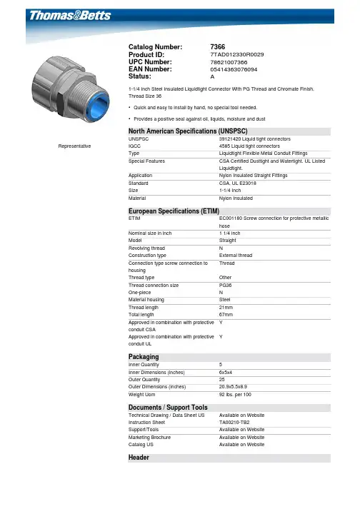
Representative Catalog Number:7366Product ID:7TAD012330R0029UPC Number:78621007366EAN Number:05414363076094Status:A1-1/4 Inch Steel Insulated Liquidtight Connector With PG Thread and Chromate Finish, Thread Size 36•Quick and easy to install by hand, no special tool needed.•Provides a positive seal against oil, liquids, moisture and dustNorth American Specifications (UNSPSC)UNSPSC39121420 Liquid tight connectorsIGCC4585 Liquid tight connectorsType Liquidtight Flexible Metal Conduit FittingsSpecial Features CSA Certified Dusttight and Watertight. UL ListedLiquidtight.Application Nylon Insulated Straight FittingsStandard CSA, UL E23018Size1-1/4 InchMaterial Nylon InsulatedEuropean Specifications (ETIM)ETIM EC001180 Screw connection for protective metallichoseNominal size in inch 1 1/4 inchModel StraightRevolving thread NConstruction type External threadConnection type screw connection tohousingThreadThread type OtherThread connection size PG36One-piece NMaterial housing SteelThread length21mmTotal length67mmApproved in combination with protectiveconduit CSAYApproved in combination with protectiveconduit ULYPackagingInner Quantity5Inner Dimensions (inches)6x5x4Outer Quantity25Outer Dimensions (inches)20.9x5.5x8.9Weight Uom92 lbs. per 100Documents / Support ToolsTechnical Drawing / Data Sheet US Available on WebsiteInstruction Sheet TA00210-TB2Support/Tools Available on WebsiteMarketing Brochure Available on WebsiteCatalog US Available on WebsiteHeader3D Model Available on Website For further technical assistance, please contact us...ABB Installation Products - USA 860 Ridge Lake Blvd. Memphis, TN 38120 ABB Installation Products Technical SupportMS 3B-50860 Ridge Lake Blvd.Memphis, TN 38120Hours: 7AM - 6PM CDTMonday-FridayPhone: (888) 862-3289Fax: (901) 252-1321Email:*******************NOTE: Catalog numbers 5229 (for 1/4” liquidtight conduit) and 5330 (for 5/16” liguidtight conduit) connectors are available without locknut assembled and are NOT UL listed or CSA certified. This guide has been prepared to show the proper method ofinstalling T&B® liquidtight connectors. The selection of theproper raceway, the most appropriate T&B® connector pluscorrect installation techniques will provide both the highperformance and reliability demanded by specifying engineers.Following are the characteristics and specifications that shouldbe the criteria for selection of high quality connectors such asthe T&B® line.Features• Safe-Edge™ Steel grounding cones means no sharp edges.• Blue nylon insulated throats• Double bevel nylon sealing rings means easier installation.• PVC coated connectors*Read and understand all instructions andsafety information before use. Be awareof proper usage and potential hazards.IMPORTANTWARNING:Risk of shock, disconnectpower before installationCAUTION: Product should be installed bya qualified electrician in accordance withnational and local electrical codes.1 of 2INSTALLATION GUIDELiquidtight connectorsFor Liquidtight flexible metallic conduitWear hand protection.Wear eye protection.Figure 3Figure 2Installation instructions1. Cut the flexible conduit with a clean square end cut. (Figure 1)• Use metal jig (available from conduit manufacturers). • Use 32 Tooth/ln. no. set, sharp hacksaw.• For high production use 24-32 Tooth/ln. wavy set, power band saw, not more than 400’/minute.• Do not use an abrasive wheel.2. Assembly• For 5000, 7000, and 9000 series & PVC coated 3300 series. (Figure 2)a. Slide on gland nut.b. Slide on nylon sealing ring.c. Thread in Safe Edge™ Cone.• For PVC coated connector, use the same assembly method, except tighten with smooth jaw wrench. If gouging occurs exposing metal, PVC cement is recommended.• For knockout applications, use T&B® 140 series locknuts and 5260 series sealing gaskets. (Purchase separately)• For 7000 and 9000 series , order locknut separately.“Space Saver” Chase® connector assembliesOutside of knockout, 3 style Chase® connector bodies. (Figure 3)• Lock-up can be made by tightening Chase® Nipple to body or by turning body onto Chase® Nipple.Figure 1Liq ui d t i g h t c o n n e c t o r s | I n s t a l l a t i o n g u i d e | T A 00210 F — Warranty: /ecpwarranty —We reserve the right to make technical changes or modify the contents of this document without prior notice. With regard to purchase orders, the agreedparticulars shall prevail. ABB does notaccept any responsibility whatsoever forpotential errors or possible lack ofinformation in this document.We reserve all rights in this document and in the subject matter and illustrations contained therein. Any reproduction – in whole or in part – is forbidden without prior written consent of ABB.Copyright© 2019 ABB. All rights reserved. 2 of 2。
目录1.产品概述 (2)2.主要特性 (2)3.系统框图 (2)4.封装及引脚说明 (3)5.功能描述 (5)5.1输出模式和选项脚位 (5)5.2按键最长输出时间 (5)5.3低功耗模式 (5)5.4灵敏度调整 (5)6.应用电路 (6)7.电气特性 (7)7.1电气特性极限参数 (7)7.2直流特性 (7)8.封装信息 (8)8.1SOT23-6封装 (8)8.2DFN2x2-6L封装尺寸 (9)8.3DFN2x2-6L编带信息 (10)8.4DFN1x1-4L封装尺寸 (11)8.5DFN1x1-4L编带信息 (12)9.历史记录 (12)单触控单输出IC文件编号:PT-DS210071.产品概述PT2041A是一款单通道触摸检测芯片。
该芯片内建稳压电路,提供稳定电压给触摸感应电路使用,同时内部集成高效完善的触摸检测算法,使得芯片具有稳定的触摸检测效果。
该芯片专为取代传统按键而设计,具有宽工作电压与低功耗的特性,可广泛地满足不同消费类应用的需求。
2.主要特性⚫工作电压范围:2.4~5.5V⚫工作温度范围:-40~85℃⚫抗干扰性能优良:内置稳压电路、上电复位、低压复位功能及环境自适应算法等多种措施⚫待机工作电流:典型值2uA@V DD=3V/无负载⚫按键最长响应时间:低功耗模式下约200ms@V DD=3V⚫可接外部电容(1~50pF)调整触摸灵敏度⚫输出模式选择(TOG):同步输出或锁存(toggle)输出⚫CMOS输出(QC)有效电平选择(AHLB):高电平或低电平输出有效⚫按键最长输出时间:16秒(±30%)⚫上电约0.4秒的初始化时间,此期间内不要触摸检测点,且此时所有功能被禁止⚫HBM ESD:大于2KV⚫封装形式:SOT23-6、DFN2*2-6L、DFN1*1-4L3.系统框图传感器震荡电路时序计算器 &功能选项控制电路系统振荡电路传感器 &参考检测电路触摸检测电路输出&驱动电路TCHQCTOGAHLB图1 系统框图4.封装及引脚说明QC VSS TCHTOGVDDAHLB 34 PT2041AT6图2 PT2041A SOT23-6管脚示意图TCH VSS QCAHLBVDDTOG65423PT2041AD6 1图3 PT2041A DFN2x2-6L管脚示意图注:引脚布局与SOT23-6反向VDD TCHQCVSS43 2PT2041AD41图4 PT2041A DFN1x1-4L封装管脚示意图注:固定为同步输出模式,输出高电平有效表1引脚说明表223VSS P地312TCH I触摸感应输入46/AHLB I-PL 输出高电平有效或低电平有效选择0(默认值):高电平有效;1:低电平有效551VDD P电源64/TOG I-PL 输出模式选择0(默认值):同步输出;1:锁存(toggle)输出引脚类型:I:CMOS输入O:CMOS输出I/O:CMOS输入/输出P:电源/接地I-PH:CMOS输入内置上拉电阻I-PL:CMOS输入内置下拉电阻5.功能描述5.1 输出模式和选项脚位AHLB 和TOG 选项脚位为锁存类型:上电默认状态为0,若上电前管脚被接至VDD ,则上电后状态变为1,且不会有电流漏电。
圣敏感温线缆说明书圣敏感温线缆是一种应用广泛、性能优良的电气设备。
它具有高温、耐腐蚀、耐磨损等特点,广泛用于各种行业的电气设备系统、自动化控制系统等场合。
一、产品特点1.高温性能:圣敏感温线缆使用高温材料,耐高温度达到260℃,能满足大多数高温场合的需求。
2.耐腐蚀:圣敏感温线缆采用特殊材料加工,耐腐蚀性能优异,长期使用不易受到外界腐蚀的影响。
3.耐磨损:圣敏感温线缆使用特殊的抗磨损材料加工,能够耐受机械或物理力的不断摩擦,延长使用寿命。
二、使用方法圣敏感温线缆可以用于各类接线设备或仪器中,使用前需要注意以下事项:1.安装前需要先检查线缆的外观是否有破损或电线是否裸露,如有损伤应及时更换。
2.应选择合适电源以满足线缆的额定电流,避免过载使用。
3.在使用过程中,线缆应注意防潮、防水、防尘等措施,以保证线缆的正常使用寿命。
4.不得将线缆暴露在强阳光下,以免影响使用效果。
三、维护方法1.使用圣敏感温线缆要注意定期清洁,避免灰尘积累影响电线信号传输。
2.线缆在使用过程中如发现电线断裂或短路现象,应及时更换,避免影响设备正常使用。
3.如果长期不使用圣敏感温线缆,应储存在干燥阴凉处,避免受潮、日晒等因素影响。
四、注意事项1.在使用过程中要避免线缆频繁拔插,避免损坏插头。
2.如需对线缆设备进行维修保养,应选择专业技术人员或授权维修点进行维修保养。
3.在选择圣敏感温线缆时,应注意选择符合使用环境的型号,避免使用不当造成安全隐患。
圣敏感温线缆的应用广泛,使用方法简单,维护简便。
在使用过程中需注意各项细节,保证设备的正常运行。
希望本文对于各位用户的使用、维护提供一些有帮助的指导。
聚乙烯双屏蔽铜缆说明书条目:1.0 概述2.0 导体3.0 绝缘4.0 对绞5.0 四芯绞和导线6.0 多股7.0 填充物8.0 屏蔽9.0 鉴定10.0 线带11.0 护套12.0 导体阻抗13.0 互电容14.0 不平衡电容15.0 绝缘阻抗16.0 护套火花测试17.0 无用的对18.0 电缆两端表格:1.0 导体和绝缘-规格和机械性能2.0 阻抗和互电容3.0 配色方案4.0 颜色带5.0选配,护套厚度和外径附录:1.0 水渗透性测试范围这份说明书对由单元制网状聚乙烯绝缘,凝脂填充,铜导体组成的双电缆定义了技术要求,它是由双屏蔽,聚乙烯外护套和聚乙烯内护套构成。
这种由聚乙烯做护套的铜缆是提供给10,20,50和100对0.5mm的铜缆用的。
这种线缆是用在工作于标称波长的传输系统,这种铜能同时在模拟和数字传输中使用。
这种线缆有完整构造和能在湿气中保护线缆的铜和其组成部分。
以下有三个类别的属性来描绘其几何,铜,传输和机械参数:.铜属性是那些在整个布线和安装中保留下来的参数;.线缆传送时,提倡用线缆参数;.链接属性是级联电缆所特有的,描述的方法用以测量,建模,系统设计和其他考虑。
1.0 概述这份说明书为铜缆的采购定义了技术要求。
在模拟和数字传输中,这份说明书是针对聚乙烯双屏蔽双铜缆设计的。
这种电缆能用在聚乙烯管道或者是已安装在直径100毫米管道内的分离器中,它要求管道线缆能用在上述直线,长距离类型的清洁管道中。
这些线缆是用特定的鼓长度来制定的。
投标者或投标人在他们线缆允许的最大牵引张力和最小弯曲半径上必须给出详情,至少在25年的线缆服务中要保持一致。
这种线缆将使用传统的牵引技术来安装。
投标者或投标人在他们的线缆设计中必须使用封底安装,对它的设计结构给出详情和该设计是否实地验证过。
和这份说明书有关的任何信息要在合同发表前提出,应该向发投标邀请书的部门申请。
2.0 导体2.1 线缆中每根导体应当包括一根实心标准铜线,光滑,圆整,质量统一,无缺陷,其直径符合表1。
目录聚四氟乙烯系列一、F4覆铜箔板类●聚四氟乙烯玻璃布覆铜箔板(F4B—1/2)…………………………………………●宽介电常数聚四氟乙烯玻璃布覆铜箔板(F4BK—1/2)…………………………●宽介电常数聚四氟乙烯玻璃布覆铜箔板(F4BM—1/2)…………………………●宽介电常数聚四氟乙烯玻璃布覆铜箔板(F4BMX—1/2)[新品推荐]…………●宽介电常数聚四氟乙烯玻璃布覆铜箔板(F4BME—1/2)[新品推荐]…………●介电常数2.94覆平面电阻铜箔高频层压板[新品推荐]……………………●金属基聚四氟乙烯玻璃布覆铜箔板(F4B—1/AL.CU)[新品推荐]……………●绝缘聚四氟乙烯覆铜箔板(F4T—1/2)…………………………………………复合介质基片系列一、TP类●微波复合介质覆铜箔基片(TP—1/2)…………………………………………二、TF类●聚四氟乙烯陶瓷复合介质覆铜箔基片(TF—1/2)……………………………二、F4漆布类…………………………………………………………………………●防粘布(F4B—N)●绝缘布(F4B—J)●透气布(F4B—T)聚四氟乙烯玻璃布覆铜箔板F4B—1/2本产品是根据微波电路的电性能要求,选用优质材料层压制成,它具有良好的电气性能和较高机械强度,是一种优良微波印制电路基板。
技术条件宽介电常数聚四氟乙烯玻璃布覆铜箔板F4BK—1/2B系本产品是采用玻璃布和聚四氟乙烯树脂经科学配制和严格工艺压制而成。
其电气性能比F4列有一定提高,主要体现在介电常数范围更宽。
技术条件宽介电常数聚四氟乙烯玻璃布覆铜箔板F4BM-1/2本产品是采用玻璃布、半固化片和聚四氟乙烯树脂经科学配制和严格工艺压制而成。
其电气性B系列有一定提高,主是介电常数范围更宽,介质损耗角正切值低、电阻值增大、性能更稳能比F4定。
技术条件新品推荐宽介电常数聚四氟乙烯玻璃布覆铜箔板F4BMX—1/2本产品是采用玻璃漆布、半固化片和聚四氟乙烯树脂经科学配制和严格工艺压制而成。
PT封隔器1 用途PT封隔器是加压坐封悬挂式封隔器,用于套管井的测试。
2 结构及工作原理PT封隔器由旁通、密封元件和卡瓦总成组成。
旁通孔有较大旁通面积,能旁通起下钻液流和平衡封隔器解封前上下方的压力。
旁通道由端面密封关闭。
PT封隔器3 技术规格4 使用操作要点选择J形槽:PT封隔器设有J形槽和和定位凸耳控制系统。
封隔器有两种J形槽,一种用于自动保险,另一种用于手动保险。
自动保险槽的座封方法是:上提,右旋,在保持右旋扭矩的同时下放座封封隔器。
解封时,上提,此时凸耳将自动沿斜坡向上,到达J形槽解封位置。
手动保险槽的座封方法是:上提,右旋工具四分之一转并下放坐封封隔器,解封时,上提,并左旋工具四分之一转。
当工具进入井下衬管时,推荐用自动保险槽。
因为,还能保证定位凸耳不会偶然滑入坐定槽,并导致封隔器座封。
在斜井中不能用左旋扭矩保险封隔器时,也推荐使用自动保险槽。
只要能顺利地坐封、解封和再坐封,建议用手动保险槽。
5 注意事项1、每次作业后,都应将工具完全拆开、清洗。
用肉眼检查所有的密封面和接头丝扣是否有损坏。
已发现所有有损坏了的部件都应更换。
2、按图纸组装,堵死两端,试内压35MPa,保压3min,应无渗漏与降压现象。
3、下井前将封隔器支起,用手将摩擦块套筒上下动作次数,检查机械卡瓦是否动作灵活。
如不灵活需修理灵活为止。
4、下PT封隔器前,必须用标准刮管器清理管壁至射孔井段以下。
以保证封隔器起下顺利,坐封严密。
刮管后,立即用压井洗液井,充分循环,力求将井内污物及杂质除净,并且要求全井筒内压井液性能一致。
5、连接管柱时,各道丝扣必须涂好密封脂,打紧背钳,防止井下管柱正转坐封。
6、下管柱时必须缓慢平稳,不得猛刹、猛放。
如发现遇阻应立即上提(遇阻加压不得超过5吨),然后慢慢下放。
如果多次提放仍下不去则应立即起钻,排除故障后再下。