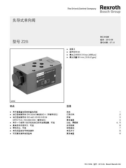
z2s6 样本说明文档
- 格式:pdf
- 大小:1.91 MB
- 文档页数:12


Series 6, 2-in-1 cooktop withintegrated ventilation, 80 cm,surface mount without framePVQ811F15E1 x Slider for unducted recirculation, 1 x Clean Air Plus odor filterHEZ9ES100 Espresso maker 4 cups, HEZ9FE280 Iron pan Ø 18 / 28 cm, HEZ9SE030 Set of 2 pots and 1 pan, HEZ9SE040 4 pieces Set, HEZ9SE060 6 pieces Set, HEZ9VDKE1 Exhaust kit, HEZ9VDKR0 Recirculation kit 2 L-bow (70cm), HEZ9VDKR1 Recirculation kit S and L-bow (60cm), HEZ9VDKR2 Recirculation kit 1x L-bow,HEZ9VDSB1 90° flat duct bend horizontal, HEZ9VDSB2 90° flat duct L vertical, HEZ9VDSB3 90° flat duct M vertical, HEZ9VDSB4 90° flat duct S vertical, HEZ9VDSI0 Adapter round-flat, HEZ9VDSI1 90°Adapter round-flat, HEZ9VDSM1 Straight tube 500mm, HEZ9VDSM2 Straight tube 1000mm, HEZ9VDSS1 Connector sleeve (female), HEZ9VDSS2 Flex sleeve (female), HEZ9VEDU0 Acoustics Filter,HEZ9VRCR0 cleanAir recirculation replenishment fil, HEZ9VRCR1 Clean Air Plus odor filter (replacement), HEZ9VRPD1 Plinth Diffusor The induction cooktop with integrated ventilation module: combines induction with ventilation technology for perfect results.• DirectSelect: Direct, simple selection of the desired cooking zone, power and additional functions.• CombiZone: combine two induction cooking zones to heat large cookware.• AutoOn function: the extraction automatically switches on when the cooktop is activated.• MoveMode: the automatic setting of cooking levels allows fast boiling on the front and simmering on the rear cooking zone.• PowerBoost: up to 50% more power for faster heating on your induction cooktop.Product name/family: .......................................Cooking zone ceramic Built-in / Free-standing: ...........................................................Built-in Energy input: ...........................................................................Electric Min. required niche size for installation (HxWxD): ....223 x 750-750 x 490-490 mmWidth of the appliance: ..........................................................802 mm Dimensions (HxWxD): .........................................223 x 802 x 522 mm Dimensions of the packed product (HxWxD): .....430 x 940 x 660 mm Net weight: ..............................................................................24.9 kg Gross weight: ..........................................................................31.3 kg Residual heat indicator: .........................................................separate Location of control panel: ..........................................................Front Basic surface material: ..................................................Ceramic glass Color of surface: .........................................................................Black Length electrical supply cord: ..............................................110.0 cm Sealed Burners: ..............................................................................No Heating with booster: .....................................................................All Power of 2nd heating element (kW): ........................................3.6 kW Number of power settings: .................................9-stage + 2 intensive Max. air extraction: ..............................................................500 m³/h Boost position output recirculating: ..................................595.0 m³/h Max. air recirculation: ..........................................................487 m³/h Boost position air extraction: ...............................................622 m³/h Noise level: ..............................................................69 dB(A) re 1 pW Odour filter: ...................................................................................No Operating Mode: ...............................................................Convertible Voltage: .................................................................220-240/380-415 V Frequency: ...........................................................................50; 60 Hz Main colour of product: ..............................................................Black Length electrical supply cord: ..............................................110.0 cm Min. required niche size for installation (HxWxD): ....223 x 750-750 x 490-490 mmDimensions (HxWxD): .........................................223 x 802 x 522 mm Dimensions of the packed product (HxWxD): .....430 x 940 x 660 mm Net weight: ..............................................................................24.9 kg Gross weight: ..........................................................................31.3 kg Included accessories: 1 x Slider for unducted recirculation, 1 x Clean Air Plus odor filterSeries 6, 2-in-1 cooktop withintegrated ventilation, 80 cm,surface mount without framePVQ811F15EThe induction cooktop with integrated ventilation module: combines induction with ventilation technology for perfect results.- 80 cm: space for 4 pots or pans.Flexibility of cooking zones- 2 Combi zones- : use bigger cookware by connecting two classic cooking zones into one large zone.- Cooking zone front left: 190 mm, 210 mm, 2.2 KW (max. power 3.7 KW)- Cooking zone rear left: 190 mm, 210 mm, 2.2 KW (max. power 3.7 KW)- Cooking zone rear right: 190 mm, 210 mm , 2.2 KW (max power 3.7 KW)- Cooking zone front right: 190 mm, 210 mm, 2.2 KW (max. power 3.7 KW)Usage convenience- Direct Select 1.0 Touch Control: directly control the power with the imprinted touch bar.- 17 power levels for each cooking zone: precisely adapt the heat with 17 power levels (9 main levels and 8 intermediate levels).- Timer with automatic switch off for all zones- : switches off the cooking zone at the end of the time set (e.g. for boiled eggs).- Alarm: an alarm sounds at the end of the time set (e.g. for pasta). Time saving & efficiency- PowerBoost function - reduce the time to heat up large quantities of water: boil water more quickly thanks to 50% more energy than at the highest standard level.- Move Mode - 2 Automatic Power Levels: increase or decrease the power level simply by moving the pot forwards or backwards.- QuickStart - Quick and automatic first pot detection: when switching on, the cooktop automatically selects the cooking zone with cookware (placed in off-mode).- ReStart - Quickly reinstates previous settings: in case of unintentional switch-off, restore all previous settings by switching on the cooktop again within 4 seconds.Design- FramelessSafety- Digital 2-stage residual heat indicator: indicates which cooking zones are still hot or warm.- Childproof lock: prevent unintended activation of the cooktop.- WipeProtection: wipe overboiled liquids without unintentionally changing settings (blocking all touch buttons for 30 seconds).- Main switch: switch off all cooking zones at the touch of a button. - Automatic safety switch-off: for safety reasons, heating stops after a preset time without interaction (customisable).- Energy consumption display: shows the electricity consumption ofthe last cooking process.Installation- Dimensions of the product (HxWxD mm): 223 x 802 x 522- Required niche size for installation (HxWxD mm) : 223 x 750 x (490 - 490)- Min. worktop thickness: 16 mm- Connected load: 7.4 KW- PowerManagement Function: limit the maximum power if needed (depends on fuse protection of electric installation).- Power cord: 1.1 m, Cable includedIntegrated ventilation downdraft system- Induction cooktop with fully integrated high-performance downdraft extractor.- Suitable for ducted or recirculated extraction configuration (incl. differentiated software modes). Installation accessories for unducted recirculation, among these four cleanAir odor filters and a telescopic slider element, are included in the cooktop. Accessories for other installation options are available, details in the planning notes.- Aesthetically integrated fully flush air intake design with floating, heat resistant glass ceramics element for free movement and placement of cookware.- Ventilation system with 9 electronically controlled fan power levels and 2 Boost-/Intensive fan power levels (with automatic revert) via Direct Select 1.0 Touch Control user interface:- Automatic switch-on of ventilation system when a cooking zone is used.- Automatic delayed shut-off after cooking to erase residual odors after cooking (in specific ultra low-noise fan level, 12min in ducted extraction, 30min in recirculated extraction, can be shut-off manually).- Fully manual control possible via Direct Select 1.0 Touch Control. - High-performance, low-noise blower with energy-effcienctBLDC-technology. High extraction rates at very low noises with pleasant noise frequencies through psycho-acoustically and aerodynamically optimized interieur with enclosed, non-visible blower. Highly pressuredrop resistant even with longer and more complex ductings.- - Convenient one-hand removal of unit via floating glass ceramics handle.- Integrated, large-scale, high performance stainless-steel grease filters with 12 filtration layers and one black top layer for enhanced aesthetical integration.- All parts of the unit are easy-to-clean, fully dishwasher safe and heat resistant.- (Upper) Liquid collector unit with 200ml of capacity for standard accidental spillages or cooking condensate.- Powerful drainage system for spillages that exceed 200ml of liquids.- Liquid safety collector with additional capacity of 700ml for more severe accidental situations. Dishwasher safe. Easily accessible and detachable from below.- Overall capturing capacity of 900ml (200ml + 700ml).- Watertight blower system.- Extraction performance in ducted extraction (according to EN 61591): min. normal setting 154 m3/h , max. normal setting 500m3/h , max. Boost-/Intensive setting 622 m3/h .- Extraction performance in recirculated extraction (according to EN 61591): min. normal setting 117 m3/h , max. normal setting 487m3/h , max. Boost-/Intensive setting 595 m3/h.- - Noise level in ducted extraction (Sound power level according toEN 60704-3): min. normal setting 42 dB re 1 pW, max. normal setting 69 dB re 1 pW, max. Boost-/Intensive setting 74 dB re 1 pW.- - Noise level in recirculated extraction (Sound power level according to EN 60704-3. ): min. normal setting 41 dB re 1 pW, max. normal setting 68 dB re 1 pW, max. Boost-/Intensive setting 72 dB re 1 pW.- - Grease filter efficiency (according to EN 61591) 94 %.- Noise min. normal setting & max. normal setting: 42 dB & 69 dB . - - Optimized odor reduction performance for cooking applications with complex odor molecules (e.g. fish).- - Large scale filter surface with high odor reduction capabilities.- - cleanAir odor filters: Lifetime of 360 hours of cooking(non-regenerative).- - Low-noise filters with optimized psycho-acoustics.- - Easy-to-access and easy-to-remove from above.- - Replenishment cleanAir filter set 17004806 (HEZ9VRCR0) available via Bosch Online Shop / customer service.- For ducted extraction configuration: 2 x 2 Battery of directly integrated, high-performance low-noise acoustic filters for significantly lower noise and improved psycho-acoustics.Planning & installation notes- Suitable for ducted or recirculated extraction installations in 4 different options (unducted, partly and fully ducted recirculation or ducted extraction). Installation accessories for unducted recirculation, among these four cleanAir odor filters and a telescopic slider element, are included in the cooktop. The included accessories allow easy and quick installations and can be planned in all worktop depths ≥60cm. For other types of installation, one of the following accessory kits is recommended:- - HEZ9VDKR0 for partly-ducted recirculation in worktops of ≥70cm depth with max. worktop height of 960 mm.- - HEZ9VDKE1 as starter kit for ducted extraction in worktops of≥60cm depth.- To complete the fully ducted extraction or to do any other individual recirculation planning different ducting accessories are available.- Planning suggestions:- - Installation is possible in island as well as wall oriented configurations.- - The product and its accessories comply with the Needle Flame Test (according to IEC 60695-11-5) and the B1/B2 building material class (according to DIN 4102-1).- - The max. immersion depth is 223mm below glass for top mounted appliances and 227mm for flush installed appliances.- - The appliance must be freely accessible from below (i.e. for accessing the lower liquid safety collector).- - No false floor is necessary below the cooktop with integrated downdraft ventilation system. The drawers and/or shelves in the floor unit must be removable. The backpanel of the floor unit can be kept - only a cut-out for the air outlet is needed (position and size can be taken from the installation instructions).- - Installation kit HEZ9VRUD0 for unducted recirculation requires a vertical aperture of min. 25mm behind the backpanel of the furniture. Suggested for ideal performance are 50mm.- - The minimum worktop thickness is 16mm for top mounted and flush installed appliances with the standard installation system. Installation in even thinner worktops is also possible with the spare part: 626792.- - The overall appliance weight is 26kg - the bearing capacity and stability, in the case of very thin worktops in particular, must be supported using suitable substructures. The overall applianceweight and the worktop manufacturer's structural integrity specifications are to be taken into account.- - For partly ducted and unducted recirculation extraction installations, a return-flow aperture of ≥400cm² is to be respected in the plinth area. The aperture can be realized via outlet grids, lamella grids or subtly shortened plinths depending on the assortment of the kitchen furniture manufacturer.- - The air outlet on the backside of the appliance can directly be accessed with a male flat duct element (DN 150).- - The pressuredrop resistant blower allows longer and more complex ductings up to 8m with three 90° bows while keeping sufficient performance.- - In ducted extraction configuration a one-way flap (or backflow trap) with a maximum opening pressure of 65Pa should be installed.Series 6, 2-in-1 cooktop with integrated ventilation, 80 cm, surface mount without frame PVQ811F15E。


Wave Bathing & Transfer SystemZ210, Z220, & Z230 Product ManualZ210, Z220 & Z230ContentsImportant information 3Safety messages 4Recommended use and item dimensions 5Check your order 6Basic componentsLegs 6Back 7Seat 7Seat with calf rest 7Head blocks 8Soft fabric cover 8Chest strap and leg straps 8 AccessoriesTub stand 9Shower stand 10Tub transfer base 11Conversion kit 12 Operation and maintenance 13Cleaning and warranty 14Materials and user modifi cations 15© 2016 Rifton Equipment23• Thoroughly read and understand the information in this product manual beforeattempting to use this product. If the procedures and instructions in this product manualare not followed, serious injury or death could occur.• A qualifi ed professional must assess the appropriateness and safety of all equipment foreach user.• This product is intended for use by clients of unreliable judgment. Adult supervision isrequired at all times.• To prevent falls and injuries:○Do not use this product on rough and uneven terrain, around swimming pools, ornear stairways.○Ensure the appropriate use of straps and supports at all times. Straps and supportsare provided for the safety of the user and must be carefully adjusted for comfort andsecurity.○Tighten all adjustment knobs before use and immediately after making anyadjustments.• Do not use this product for clients outside the height and weight limits specifi ed in thismanual.• To prevent pinching or crushing, ensure that all hands and feet are clear of moving partsduring adjustment.• To prevent structural failure, which may result in serious injury or death:○Inspect this product and accessories regularly for loose or missing screws, metalfatigue, cracks, broken welds, missing attachments, general instability or other signsof excessive wear.○Immediately remove this product from use when any condition develops that mightmake operation unsafe.○Do not use Rifton components or products for any purpose other than theirintended use.• To prevent drowning, use extra caution when using bath chair in a bathtub.4Recommended useThe Rifton Wave Bathing and Transfer System is a Class 1 medical device. It is intendedto provide a stable, quick-drying seat for bathing or showering for individuals withdisabilities. Adjustments and additional supports are available for the safety and comfortof the user. The tub transfer base enables easier transfers over the bathtub for large users. User and item dimensionsSeat depth10½ (27)13 (33)17 (43)Seat width15 (38)15 (38)17½ (44)Back height23 (58)26½ (67)32 (81)Seat height2/7 (5/18)2/7 (5/18)2/7 (5/18)Seat height including tub stand12½-18½ (32-47)12½-18½ (32-47)12½-18½ (32-47)Seat height including shower stand27½ (70)27½ (70)27½ (70)Seat height including transfer base21½-27½ (55-70)21½-27½ (55-70)21½-27½ (55-70)Length of mesh area when fl at35 (89)41 (104)50½ (128)(without calf rest)Length of mesh area when fl at42½ (108)49 (124)61 (155)(with calf rest)Width of base18 (46)18 (46)21 (53)Length of base when fl at29½ (75)29½ (75)29½ (75)Tub stand height (legs fl at)8 (20)8 (20)8 (20)Tub stand length (legs fl at)39 (99)39 (99)39 (99)Tub stand width (legs fl at)17½ (44)17½ (44)17½ (44)Shower stand height22 (56)22 (56)22 (56)Shower stand width27 (69)27 (69)27 (69)Shower stand length34 (86)34 (86)34 (86)Maximum tub edge height for19 (48)19 (48)19 (48)transfer baseMax. working load - Lbs. (kg)75 (34)150 (68)250 (114)Back and seat angle adjustments0˚, 15˚, 30˚, 45˚, 60˚, 75˚56Check your orderYour Wave Bathing & Transfer System comes with the bath chair completely assembled. You will only need to attach it to whatever base you are using, and position the backrest, seat and headblocks appropriately before use.Figure 6a132Figure 6b The Wave bath chair comes in small, medium, and large sizes. It can be used with or without a tub stand, shower stand, or tub transfer base. A soft fabric cover with padding is part of the standard product.LegsThe bath chair legs adjust to raise or lower the chair by 7" (18 cm). You can also get an intermediate height by raising the front legs only.To raise or lower the chair (see fi gure 6a): 1. Pull crossbar outward.2. Rotate legs up or down.3. Push crossbar in to engage.The bath chair folds fl at for storage (see fi gure 6b).Basic componentsFigure 7aFigure 7bBackThe bath chair back adjusts in 15°increments with a one-hand latch. Toadjust the back (see fi gure 7a):1. Squeeze gray handle (A) up behindchair back.2. Rotate back to desired position.3. Release gray handle to engage thelatches at desired angle.SeatThe seat angle adjusts in 15° increments.Increasing the angle can help prevent the userfrom sliding forward on the seat. To adjustthe seat (see fi gure 7b):1. Pull the two gray triggers (B) under thefront edge of the seat towards you.2. Rotate the seat to the appropriateposition.3. Release both triggers to engage thelatches.Seat with calf rest(see fi gure 7c)To prevent seriousinjury, fold calf restdown during transfers. Full weight oncalf rest may break it or tip chair.If you purchased the calf rest option, itis attached to the seat front and adjustsindependently of the seat. To adjust thecalf rest:1. Hold the calf rest fi rmly while pressingthe gray buttons (C) on both sides.2. Adjust the calf rest to the desired angle.3. Release both gray buttons engagelatches.Figure 7cABC7Head blocksSlide the head blocks in and out on the strap to adjust spacing. They can also be positioned at any height using the hook and loop fasteners at the back(see fi gure 8a).Soft fabric coverThe fabric cover for the bath chair is madeof soft polyester knit for comfort. Extra padding between the fabric and the frame softens surface contact.Chest strapsTo preventstrangulation, ensure correct adjustment and positioning of the chest strap at each use.Two choices of chest straps are available in soft polyester knit material.The standard chest strap’s top portion encircles the user, and the back portion attaches around the bath chair back with a buckle (see fi gure 8b).The chest strap with lateral positioning also buckles around the back of the chair, but has additional side pieces (A) that stabilize the chest strap laterally (seefi gure 8c).Leg strapsFasten the leg straps to the seat with the buckle underneath. Use the leg straps to secure the user’s legs (see figure 8d).Figure 8b: standard chest strapFigure 8aFigure 8c: chest strap with lateral positioning Figure 8dA89Figure 9bFigure 9cFigure 9aAccessoriesTub standTo prevent falls, make sure all fourchair legs are fi rmly latched in the sockets on the stand before using the tub stand.The tub stand (see fi gure 9a) raises the bath chair to a seat height of either 12½" (32 cm) or 18½" (47 cm), depending on whether the tub stand legs are raised or lowered (see page 6).To attach the chair onto the tub stand:1. Rotate front and back bath chair legs down into the vertical position (see page 6).2. Insert the legs into the four sockets.3. Press down fi rmly until the latches click into place.To release (see fi gure 9c):1. Press down on both gray latches at one end of the tub stand.2. Firmly lift up the bath chair, so that the two latches on the other end disengage.The tub stand is not sized to fi t onto the showerstand or another tub stand.NOTICE10Figure 10aFigure 10bShower standTo prevent falls, make sure all fourchair legs are fi rmly latched in the sockets on the stand before using the shower stand.The shower stand puts the bath chair on wheels at standing height for the caregiver. All three sizes of bath chair fi t on the same shower stand (see fi gure 10a).To attach (see fi gure 10b):1. Rotate front and back bath chair legs down into the vertical position (see page 6).2. Insert bath chair legs into the shower stand sockets.3. Press down fi rmly until the gray latches (A) engage.To release (see fi gure 10c):1. Press down on both gray latches (A) at one end of the shower stand.2. Lift up the bath chair, and the latches at the other end will disengage.Figure 10cAA11Tub transfer baseTo prevent falls, make sure frontwheels are locked during transfers.The tub transfer base enables clients in the bathchair to be transferred over a bath tub with zero lifting.To set up base (see fi gure 11a):1. Squeeze latches (A) on underside of base at both ends, fold legs out until they click into place (see fi gure 11a).2. Place legs of the wider end of the transfer base in bathtubTo install bath chair onto tub transfer base(see fi gure 11b):1. Rotate front and back bath chair legs up into the horizontal position (see page 6).2. Slide crossbar of front legs under the white hook (B) on the narrower end of the transfer base.3. Push back of bath chair down fi rmly to latch bar of rear bath chair legs under the gray latch (C).Transfers:1. To rotate top platform, press press either of the gray buttons (D) at one of the front corners. Start transfers with bath chair facing out from the tub.2. Pull tub transfer base forward if desired and lock wheels. This allows room to use a mechanical lift if needed (see fi gure 11c).3. Transfer user onto bath chair seat and secure with strap(s).4. Release wheel brakes, push tub transfer base over the tub and lock wheels (see fi gure 11d).5. Rotate bath chair 90°, lifting user’s legs over side of tub (see fi gure 11e).Figure 11cFigure 11aFigure 11bABCFigure 11dFigure 11e D12Figure 12aSwitching your tub transfer base from right-facing to left-facing confi guration (or the reverse):1. Remove the two screws with a 5/32” hex tool. Remove the two plastic glides (A) and the plastic plug (B) from the third hole and lift off the top platform (easier to do from the back). (see fi gure 12a).2. Pry out the long plastic stop (C) from the groove as shown. You may need a screwdriver or other tool to pull it out (see fi gure 12b).3. Insert the plastic stop (C) on the other end of the same groove as shown. Then slide the rear slider (D) over until it hits the stop (see fi gure 12c).4. Set the top platform on again; now the rear slider (D) should be in the other rear hole as shown (see fi gure 12d).5. Insert the two screws again and tighten with the 5/32” hex tool. Press the plastic plug (B) into the empty third hole. Now your tub transfer base is ready to use in the opposite confi guration.Conversion kitThe conversion kit converts the small pink or blue Rifton bath chairs to a medium size, tool-free (see fi gure 12e). Call customer service to order.Figure 12bFigure 12cFigure 12dABCCDDFigure 12eWithout calf rest With calf restOperationThe Rifton bath chair is intended for use in a bathtub or shower. It’s adjustability and accessories enable bathing or showering clients with a wide range of disabilities. Theseat and back angles adjust easily to accommodate positioning needs. Head Blocks,chest straps, and leg straps are designed for the safety of the user, and must be carefullyadjusted for comfort and security. The bath chair legs can be placed securely in twopositions to raise or lower the bath chair prior to use.MaintenanceThis product is designed and tested for an expected life of 5 years when used andmaintained in accordance with this manual. At all times, users must ensure that theproduct remains in a safe and useable condition, including regular maintenance andinspections as specifi ed in this manual.To prevent structural failure, which may result in serious injury or death:• Inspect this product and accessories regularly for loose or missing screws, metalfatigue, cracks, broken welds, missing attachments, general instability or other signs of excessive wear.• Immediately remove this product from use when any condition develops that mightmake operation unsafe.• Do not use Rifton components or products for any purpose other than theirintended use.• Replace or repair components or products that are damaged or appear to be unstable.• Use only Rifton authorized replacement parts. Order information for replacement partsis provided on the back of this product manual.1314Figure 14aCleaningThe Rifton bathing system is designed for easy cleaning.Remove the fabric cover by adjusting both the seat and back to a near vertical position and pulling cover from frame, seat part fi rst (see Figure 14a).Fabric parts should be washed and dried at a warm (100°F/40°C) setting. Use mild detergent. Rinse well. Disinfect frame and fabric with a commercial disinfectant, or a solution of up to 10% bleach. Rinse well. The straps with hook and loop closures may be laundered. Engage the closures before washing. Do not iron.Excessive use of bleach and high temperatures may damage the fabric. Do not iron.Tub stand, shower stand, tub transfer base and frame parts may be cleaned using normal cleaning products. Casters will give the best performance if cleaned regularly by spraying from underneath with a high-pressure water hose. Do not use chemicals or lubricants.Warranty statementIf a Rifton product breaks or fails in service during the fi rst year, we will replace itfree of charge.Materials• Steel hardware items (nuts, bolts, screws, etc) are stainless steel.• Fabric is a polyester knit, cushioned with polyester spacer fabric, with nylon hook andloop fasteners.• Frames are made with powder-coated aluminum.• Plastic components are typically injection molded from a variety of industrial resins.All materials are latex, lead and phthalates free.User modifi cationsTo prevent serious injury or death, do not modify or alter Riftonin conjunction with products from other manufacturers. Rifton does not accept responsibility for any modifi cations or alterations made to our components orproducts after they leave our premises. Customers modifying or altering our components or products, or using them in conjunction with products from othermanufacturers, do so at their own risk.15。
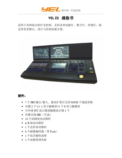
YEL Z2 规格书适用于各种场合的灯光控制,支持各类电脑灯、数字灯、常规灯,稳定性坚若磐石,设计与控制快捷方便。
硬件:∙7个DMX输出/输入, 最高扩展可支持65536个通道参数∙内置2个14.1英寸触摸屏+1个9英寸触摸屏∙可外接DVI显示器或触摸显示器1个∙内置无线DMX(可选)∙15个高精度电动推杆∙A/B场电动推杆∙1个总控电动推杆∙6个耐磨编码器(带Push)∙1个高灵敏轨迹球∙1个高精度调光轮∙2个千兆以太网口∙4个USB2.0口∙内置键盘抽屉∙独立背光按键∙MIDI输入输出接口∙LTC/SMPTE时间码∙支持扩展推杆侧翼∙2个LED鹅颈灯插口∙固态硬盘1个,32G∙Intel i3 CPU∙4GB 内存∙Geforce显卡2块∙AC 宽电压电源: 90-240 V, 50/60Hz 产品包含:∙电源线1条∙鹅颈灯1个∙操作说明一份∙航空箱一个软件:∙Linux 操作系统∙系统可通过U盘安装∙节目数据可保存在硬盘或U盘∙支持DMX512,Artnet,ACN协议∙支持中英文两种语言∙支持多台联机备份∙支持手持式远程控制∙支持舞台3D效果模拟,实时现场模拟∙系统可通过U盘安装∙节目数据可保存在硬盘或U盘∙支持DMX512,Artnet,ACN协议∙支持RDM管理∙支持Wysiwyg连接∙支持LTP和HTP∙支持MIDI时间码和内部时间码∙强大的Layout管理∙支持多用户操作,并可设置各用户权限∙颜色,图案,光束,位置等各类型的素材,每种类型可存10000个∙支持10000个编组,支持10000个效果∙支持10000个程序,每个程序可包含9999个场景∙物理:∙尺寸:98cm*65cm*21cm∙净重:30kg∙。
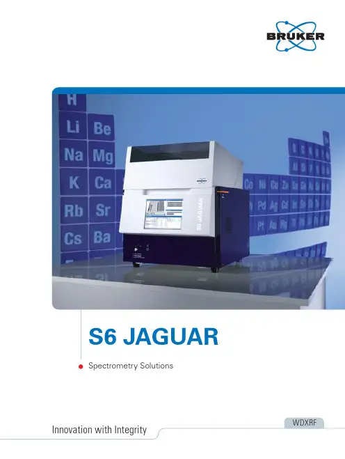
S6 JAGUAR – Outstanding Performance. Impressive Versatility. Little Space.S6 JAGUAR– Benchtop WDXRF with EasyLoad sample magazine or manual loadingThe S6 JAGUAR combines excellent analytical performance based on cutting edge technology with compact size and plug-and-analyze installation. S6 JAGUAR – the industry-ready WDXRF analyzerThe S6 JAGUAR offers more analytical power than any other compact WDXRF instrument. It features a new compact goniometer, closely coupled optics and 400 W direct excitation power. The S6 JAGUAR delivers excellent accuracy and precision based on the brand new HighSense XE detector with its ultimate linear range of two million cps. Its system components are well protected by our provenSampleCare technology, ensuring highest instrument uptime and lowest cost of operation, especially when running liquid or powder samples.S6 JAGUAR – versatility for research and academiaThe new compact WDXRF goniometer with its HighSense technology enhances both, sensitivity and spectral resolution, providing the analyticalflexibility and performance for academia and material research. With up to four sample masks for different sample sizes, up to four analyzer crystals, and two detectors, the S6 JAGUAR enables fast multi-element analysis for the entire concentration range from ppm to 100%. The standardless quantitation software SMART -QUANT WD, based on new powerful fundamental parameter algorithms, delivers accurate results even for unknownsamples.S6 JAGUAR EasyLoad with 24-position sample magazineS6 JAGUAR manual sample handlingElement range from fluorine to uraniumSuperior Flexibility and Better ResultsNiK aHigher sample throughput, enhanced analytical precision, and better trace element detection with power 50 % shorter measurement times and twice the sample throughput30 % better analytical precision with the 400 WThe significantly higher sensitivity leads to more than 30% better detection limitsLight element analysis is enhanced by more than 50% with full 400 W power at low kVUnrivalled analytical performance with the ultra compact HighSense Higher element sensitivity and excellent WDXRF resolution with the ultra-compact beam pathAccuracy and precision due to the high-performance gearsPerfect analytical flexibility with the 4-position crystal changerHigh analytical performance is provided with three crystals for the entire element range: XS-55, PET LiF200Enhanced sample throughput and detection limits with optional choice of a fourth crystalHighSense ™– More Power leads to Higher Precision and Faster SpeedBruker’s 400 W solution is twice as powerful as a 200 W system and 8 times more powerful than a 50 W systemIncrease sample throughput and quality of results –anytime at full power!The major advantage of sequential WDXRF is that every single element is analyzed with optimal instrument parameters. And the S6 JAGUAR is the master of analytical flexibility: The direct excitation power of 400 W leads to excellent element sensitivity without compromise. Full power is available at 30 kV for light elements and 50 kV for heavy elements!Make the analysis of totally unknownsamples simple, just with better detection!Just applying high-power excitation is not good enough: The S6 JAGUAR with HighSense detector technology easily covers the entire concentrationrange with linear count rates of 2 Mcps in one calibration. The HighSense XE detector for heavy elements even comes with a two times better energy resolution than conventional counters, significantly reducing inter -element effects.400 W HighSense X-ray tubeEnergy [KeV]Make the instrument a perfect fit, just by adding an additional analyzer crystalDon’t accept the standard: T o cover the entire element range in WDXRF three analyzer crystals are required.But for challenging applications, a fourth crystal will make the instrument a perfect fit. The S6JAGUAR’s HighSense goniometer is equipped with a four -position crystal changer, enabling the upgrade of the S6JAGUAR to higher performance for specific applications:-Germanium to boost sample throughput for P and S, e.g. for ASTM D 2622-XS-400 to add 35% more intensity for elements from K – Am-LiF 220 for better resolution and trace element detection from V – AmFor lower limits of detection of heavy elements, the different filters in the five-position filter changer enhances the peak-to-background ratio!Match your needs with the unsurpassed analytical flexibility of the S6 JAGUAR Complex made simple with high resolu-tion and HighSense technologyThere is no doubt: The S6 JAGUAR with the HighSense goniometer and its high spectral resolution clearly separates neighboring lines and reduces severe line overlaps. Equipped with optimal analyzer crystals, the S6 JAGUAR easily measures complex samplespectra and masters difficult samples, such as minerals and ores in geological applications and metal alloys.The WDXRF spectrometer S6 JAGUAR manages even complicated applications with its unique HighSense technologyEasyLoad tray for 20 samplesEasyLoad ONLINE for automation with two additional parking positionsS6 JAGUAR manual sample handlingS6 JAGUAR with WDXRF provides amuch better resolution than EDXRFKK b2311234545SampleCare ™and TouchControl ™for Easy Routine Operationand Independent IslandMode ™Grabber withautomatic sample detection T ube shield Filter changerMask holder Vacuum sealLiquidsDustSampleCare vacuum seal to protect against powders and liquids132Running liquid samples, loose powders or pressed pellets? S6 JAGUAR handles them all!Instrument uptime and low cost of operation are crucial to you. And you can rely on the S6 JAGUAR with Bruker’s unique SampleCare ™technology.The liquid sample detection of EasyLoad disables vacuum for liquids. Then, a shield protects the X-ray tube when loading a sample. Next, the vacuum seal protects the goniometer from spillage and dust by separating the sample and goniometer chamber. In addition, the vacuum seal lowers the consumption of helium for liquid analysis significantly.Thanks to T ouchControl ™, the operation of theS6 JAGUAR is easy and straightforward. T ouchControl enables users with minimal training to run routine samples,while restricting access to the configuration and calibra-tions. An external PC allows for full instrument control through remote access. This combines ease-of-use with optimal data integrity.S6 JAGUAR – a great deal of reliability and efficiency with SampleCare and T ouchControlFull instrument control: Routine operation and instrument setup without external PC.Select a position and the routine application, name the sample ...Instrument and sample status with full control of the AutosamplerQuick access to previous measurements via database search and direct printout... and press “Start”.Start single samples or batchesTouchControl operation of S6 JAGUAR,available for all configurationsWIZARD: Intuitive Application Setup – the easy way with SPECTRA.ELEMENTSStep-by-step guidance for application setup, includingQuality Control and Drift CorrectionStandard definition with simple copy and paste functionality: Information about elements and theirranges is used to optimize measurement method and line overlap correction (Integrated Analytical Intelligence)Definition of preparation method, including dimensions,mass and weight, for later individual calculation for every single sample123WIZARD: State-of-the-art calibration for optimal results from single to multi-element methodsInteractive optimization: On-the-fly calculation and displayof calibration curveSummary of calibration details, including offset and slope.T abulated calibration overview for every individualreference sample, including intensities, reference and calculated values, counting statistics and detection limits Automatic line overlap corrections and completely newfundamental parameter model, including variable, theoretical and empirical alpha matrix corrections1234EV ALUA TION Plug-In: Master your results with the intuitive interactive evaluationRe-evaluation of individual samples and batches withnew input including results from the fully integrated SMART -QUANT WD solution:- Adjusted compounds- Modified the evaluation type of every compound - Change the chemical species of a compound - Updated calibration1RESUL TS MANAGER: Extended reporting for every needReporting of every single detail, including elementconcentrations, intensities, sample preparation parame-ters and line settings for individual samples or batches Quick and powerful database search for every recordedsampleReporting tool for all instrument data and all solutionsincluding the fully integrated SMART -QUANT WD1231231234112311SPECTRA.ELEMENTS combines user -friendliness with functionality:Analytical performance with a simple mouse clickThe Wizard: Creating your solution could not be easier. No floating windows, just one well-organized window shows all powerful calibration options. The software dynamically updates the calibration curves whenever changes are applied.The Loader easily manages every job from a single routine sample to a large series. And the powerful Results Manager puts you in full control of your analysis results!Evaluate and get a detailed understanding of your sample: The EVAL plug-in offers interactive evaluation with all the functionality you need.SMAR T -QUANT WD –Integrated-Analytical-Intelligence ™for best results without calibrationSMART -QUANT WD is the standardless solution for the analysis of solids, fused beads, pressed pellets, loose powders, and liquids without stan-dards in your lab! It delivers reliable elemental data from Na to U with concentrations from 100% down to the ppm range. Based on WDXRF scans, it works with the completely new Fundamental Parameter (FP) engine!SMART -QUANT –the toolbox for every sample –easy to operate and powerful for best resultsMining Refinery CementGlass & Ceramics Metals ResearchPharma FoodAcademiaB r u k e r A X S i s c o n t i n u a l l y i m p r o v i n g i t s p r o d u c t s a n d r e s e r v e s t h e r i g h t t o c h a n g e s p e c i fic a t i o n s w i t h o u t n o t i c e . D OC -B 80-E X S 024 © 2018 B r u k e r A X S .a i m 02776Worldwide offices/baxs-officesOnline information/s6jaguar132 kg147 kg。
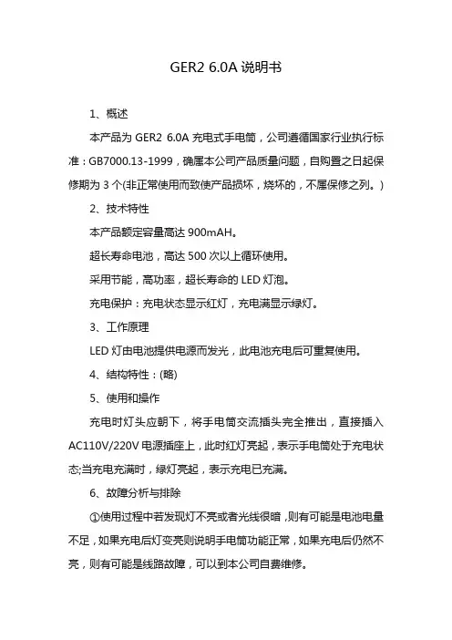
GER2 6.0A说明书1、概述本产品为GER2 6.0A充电式手电筒,公司遵循国家行业执行标准:GB7000.13-1999,确属本公司产品质量问题,自购置之日起保修期为3个(非正常使用而致使产品损坏,烧坏的,不属保修之列。
)2、技术特性本产品额定容量高达900mAH。
超长寿命电池,高达500次以上循环使用。
采用节能,高功率,超长寿命的LED灯泡。
充电保护:充电状态显示红灯,充电满显示绿灯。
3、工作原理LED灯由电池提供电源而发光,此电池充电后可重复使用。
4、结构特性:(略)5、使用和操作充电时灯头应朝下,将手电筒交流插头完全推出,直接插入AC110V/220V电源插座上,此时红灯亮起,表示手电筒处于充电状态;当充电充满时,绿灯亮起,表示充电已充满。
6、故障分析与排除①使用过程中若发现灯不亮或者光线很暗,则有可能是电池电量不足,如果充电后灯变亮则说明手电筒功能正常,如果充电后仍然不亮,则有可能是线路故障,可以到本公司自费维修。
②使用几年后若发现充电后灯不亮,则极有可能是电池寿命已到,应及时到本公司自费更换。
7、维修和保养在使用过程中,如LED灯泡亮度变暗时,电池处于完全放电状态,为保护电池,应停止使用,并及时充电(不应在LED灯泡无光时才充电,否则电池极易损坏失效。
)手电筒应该经常充电使用,请勿长期搁置,如不经常使用,请在存放2个月内补充电一次,否则会降低电池寿命8、注意事项请选择优质插座,并保持安全规范充电操作。
产品充电时切勿使用,以免烧坏LED灯泡或电源内部充电部件。
手电简不要直射眼睛,以免影响视力。
(小孩应在大人指导下使用。
)勿让本产品淋雨或者受潮。
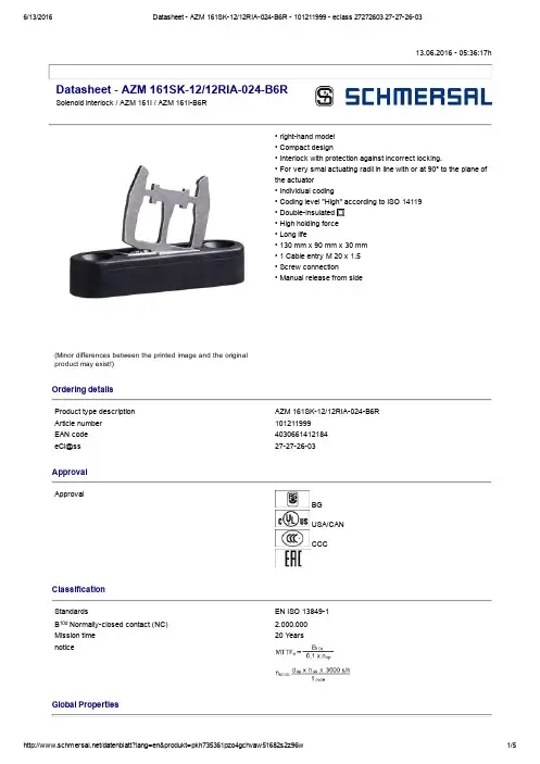
13.06.2016 05:36:17hDatasheet AZM 161SK12/12RIA024B6RSolenoid interlock / AZM 161I / AZM 161IB6R(Minor differences between the printed image and the original product may exist!)• righthand model • Compact design• Interlock with protection against incorrect locking.• For very smal actuating radii in line with or at 90° to the plane of the actuator• Individual coding• Coding level "High" according to ISO 14119 • Doubleinsulated • High holding force • Long life• 130 mm x 90 mm x 30 mm • 1 Cable entry M 20 x 1.5• Screw connection• Manual release from sideOrdering detailsProduct type description AZM 161SK12/12RIA024B6R Article number101211999EAN code 4030661412184eCl@ss 27272603ApprovalApprovalBG USA/CAN CCCClassificationStandardsEN ISO 138491B 10d Normallyclosed contact (NC) 2.000.000Mission time 20 Y earsnoticeGlobal PropertiesProduct name AZM 161IStandards EN 6094751, BGGSET19Compliance with the Directives (Y/N) Y esNumber of actuating directions3 pieceActive principle electromechanical Individual coding Coding level "High" according to ISO 14119Duty cycle Magnet 100 %Materials Material of the housings glassfibre reinforced thermoplastic, Plastic selfextinguishing, Material of the actuator Stainless steel Material of the contacts SilverHousing coating NoneWeight485 gMechanical dataDesign of electrical connection Screw connectionCable section Min. Cable section1 x 0,25 mm² Max. Cable section1 x 1.5 mm², flexibleMechanical life> 1.000.000 operationsnotice All indications about the cable section are including the conductorferrules.Emergency unlocking device (Y/N)NoManual release (Y/N)Y esEmergency release (Y/N)NoLatching force30 NPositive break force20 Npositive break travel10 mmClamping force F2000 NMax. Actuating speed2 m/sMinimum actuating radius95 mmActuating frequency max. 1000 / hAmbient conditionsAmbient temperature Min. environmental temperature−25 °C Max. environmental temperature+60 °CProtection class IP67 to IEC/EN 60529Electrical dataDesign of control element Normally open contact (NO), Opener (NC)Switching principle Creep circuit elementNumber of auxiliary contacts2 pieceNumber of safety contacts4 piecePower to unlock NoPower to lock Y esRated control voltage U s24 VAC/DCPower consumption max. 10 WRated impulse withstand voltage U imp4 kVRated insulation voltage U i250 VThermal test current I the6 AUtilisation category AC15: 230 V / 4 ADC13: 24 V / 2,5 AMax. fuse rating6 A gG Dfuse To DIN EN 602691ATEXExplosion protection categories for gases NoneExplosion protected category for dusts NoneMiscellaneous dataApplicationssliding safety guard,removable guard,hinged safety guardDimensionsDimensions of the sensor Width of sensor130 mm Height of sensor90 mm Length of sensor30 mmnoticeActuating radius adjustable, minimum 95 mm, using an hexagonal key wrench 2 mm A/F (a)The actuator is not available separately.The axis of the hinge should be 11 mm above the top edge of the safety switch and in the same plane Manual release• For maintenance, installation, etc.• For manual release using M5 triangular key, available as accessoryIncluded in deliveryIncluded in delivery• Individually coded actuator• tamperproof screws• Slot sealing plugsDiagramNote Diagrampositive break NC contactactiveno activeNormallyopen contactNormallyclosed contactSwitch travel diagramNotes Switch travel diagramContact closedContact openSetting rangeBreak pointPositive opening sequence/ angleVS adjustable range of NO contactVÖ adjustable range of NC contactN after travelOrdering suffixThe applicable ordering suffix is added at the end of the part number of the safety switch. Order example: AZM 161SK12/12RIA024B6R1637...16370,3 µm goldplated contactsDocumentsOperating instructions and Declaration of conformity (en) 562 kB, 20.01.2016Code: mrl_azm161i_enOperating instructions and Declaration of conformity (jp) 767 kB, 12.04.2016Code: mrl_azm161i_jpOperating instructions and Declaration of conformity (nl) 511 kB, 15.08.2012Code: mrl_azm161i_nlOperating instructions and Declaration of conformity (da) 504 kB, 27.08.2012Code: mrl_azm161i_daOperating instructions and Declaration of conformity (de) 565 kB, 20.01.2016Code: mrl_azm161i_deOperating instructions and Declaration of conformity (pl) 589 kB, 06.04.2016Code: mrl_azm161i_plOperating instructions and Declaration of conformity (es) 444 kB, 09.03.2016Code: mrl_azm161i_esOperating instructions and Declaration of conformity (pt) 510 kB, 27.08.2012Code: mrl_azm161i_ptOperating instructions and Declaration of conformity (sv) 498 kB, 27.08.2012Code: mrl_azm161i_svOperating instructions and Declaration of conformity(cs) 586 kB, 19.04.2016Code: mrl_azm161i_csOperating instructions and Declaration of conformity (it) 562 kB, 19.04.2016Code: mrl_azm161i_itOperating instructions and Declaration of conformity (fr) 567 kB, 28.04.2016Code: mrl_azm161i_frEAC certification (ru) 809 kB, 05.10.2015Code: q_6040p17_ruImagesProduct photoDimensional drawing (actuator)Actuating radiusActuating radiusK.A. Schmersal GmbH & Co. KG, Möddinghofe 30, D42279 WuppertalThe data and values have been checked throroughly. Technical modifications and errors excepted. Generiert am 13.06.2016 05:36:17h Kasbase 3.2.2.F.64I。

前言说明书用途此说明书适用于S6II GNSS接收机(简称“S6II”)使用。
说明书简介本说明书对S6II特点、基本功能、外业测量、手簿使用、倾斜校准,主机Web应用进行了描述。
温馨提示为了您能更好的掌握使用S6II,思拓力建议您使用前仔细阅读本说明书。
如果您想获取更多仪器及软件使用信息,请咨询当地仪器购买网点技术人员或咨询思拓力总部。
责任免除使用本产品前,请务必仔细阅读本说明书,这有助于您更好地使用思拓力GNSS接收机。
广州思拓力测绘科技有限公司对您未按照说明书操作,或未能正确理解使用本产品而造成的损失不承担责任。
广州思拓力测绘科技有限公司以产品为第一竞争力,我们致力于不断为用户提供好的产品和技术服务,我们保留对使用说明书的内容进行更改而不另行通知的权利。
对说明书的编辑和印刷,我们进行过详细的检查,但不排除存在偶然偏差的可能性,说明书中的图片仅供参考,若有与产品实物存在不符之处,请以产品实物为准。
目录第一章S6II卓越型RTK简介 (1)1.1引言 (1)1.2产品特点 (1)1.3使用和注意事项 (2)第二章S6II测量系统 (3)2.1S6II主机 (3)2.1.1主机外型 (3)2.1.2底部接口 (3)2.1.3控制面板 (4)2.1.4模式查看和切换 (6)2.1.5主机自检 (6)2.2P9II手簿 (7)2.2.1外部特征 (7)2.2.2键盘及功能 (8)2.2.3手簿接口 (9)2.2.4TF卡和SIM卡的安装 (9)2.2.5手簿配件 (10)2.3主机配件介绍 (12)2.3.1仪器箱 (12)2.3.2充电器 (13)2.3.3UHF差分天线 (13)2.3.4数据线 (14)2.3.5其他配件 (14)第三章外业测量 (15)3.1静态测量 (15)3.1.1静态测量简介 (15)3.1.2静态测量作业步骤 (15)3.1.3GPS控制网设计原则 (16)3.1.4数据采集方式 (16)3.2RTK动态测量(电台) (17)3.2.1基准站架设 (17)3.2.2启动基准站 (17)3.2.3移动站架设 (17)3.2.4设置移动站 (18)3.3RTK动态测量(网络) (18)3.3.1基准站和移动站的架设 (18)3.3.2移动站的设置 (18)第四章倾斜校准操作说明 (19)4.1磁校准 (19)4.2惯导校准 (19)4.3对中杆校准 (20)第五章WebUI应用 (21)5.1位置状态 (22)5.2设置 (22)5.3下载 (23)5.4管理 (24)5.5仪器注册 (24)附录1S6II主机技术指标 (25)附录2P9II技术指标 (27)附录3电台出厂设置 (28)第一章S6II卓越型RTK简介1.1引言欢迎使用广州思拓力测绘科技有限公司的产品。
Specifications – BT-2GHardware SpecificationsTablet Model No. RSK-T06Input Methods Electromagnetic inductionInterface to Computer (Wireless/Wired)Bluetooth 1.2 (class II) /USB 1.1 Full speed Active area size6 x 4.5 inches (152 mm (W) x 114mm (H)) Dimensions (mm)239mm (W) x 251mm (H) x 30mm (D) Weight (w/ batteries) 493g (545g)Sampling Rate (Wireless/Wired)162 points/s / 183points/s Resolution 1000LpiFunction button 12 buttons (Hold 1.5seconds to work)Hot key 1 (for Bluetooth unpairing)Power supply (Wireless)1.2V AA battery x 2 (Rechargeable battery suggested) (Wired)USB bus power (no batteries needed) Battery life (rechargeable)24hrs (Continuous use)Electronic PenModel No. L7 pen (same as T-series)Battery AAA battery x 1 (1.5V)Battery life Approximately 1800 hoursProximity 8mmPen feature On/Off switch, Low battery Indicator LEDBluetooth Adaptor (enclosed)Model No. BTU02E (class II)Standard Bluetooth 2.0 + EDRBluetooth Profile Generic Access (GAP), Service Discovery Application (SDAP), Serial Port (SPP), Dial-Up Network (DUN), FAX, File transfer (FTP), LAN Access (LAP), Synchronization (SYNC), Object Push (OPP),Generic Object Exchange (GEOP), Headset (HSP), Hardcopy Cable Replacement (HCRP), Human Interface Device (HID), Basic Image Profile (BIP), Advanced Audio Distributed Profile (A2DP) Interface to ComputerUSB 2.0 RF range Up to 40m (limited condition)Security Pairing, Encryption, AuthenticationPowerUSB bus power (LED indicator for checking power status) Dimensions (mm):58.5mm (W) x 17mm (H) x 8 mm (D) Weight 6.8gOthersOperating Specification0 - 40 Celsius, 20 - 80 % Humidity Safety Standard approvals CE, FCCOS support Windows 2000/XPPackage Content Bluetooth tablet x1, L7 pen x1, Pen tip x2, Bluetooth adaptor x1,AAA battery for pen x1, AA rechargeable battery x4, battery charger x1, USB cable for USB mode x1, USB extension cable x1, Setup CD x1,User manual x1Packing dimension 358mm (W) x 273mm (H) x 81mm (D)Warranty 1 year warrantyFeatures Wireless connectionWork with Bluetooth wireless connection up to 10m Parallel usageUp to 7 devices per PC (Wireless mode) Electronic Pen AAA battery powered with two side buttons, possible to assign any mouse event(right/left click, double-click, hovering) as desiredSystem Requirements ComputersCPU: Pentium II 300MHz (800MHz or faster recommended)RAM: 128MB (256MB or higher recommended)HDD: 200MB of free spaceDisplay Colour Depth: High Colour (16bit)Internet Explorer 6 and latest service packAdobe Reader 6.0 or higherMicrosoft Office 2000 or higher Windows Operating SystemWindows 2000, Windows XP (latest service pack recommended)Bluetooth Software(Windows 2000/XP SP1)Bluetooth software version 4.0.1.2900 or higher (Windows XP SP2)Microsoft Bluetooth software (no install needed) Tablet driver Bluetooth Pen pad driver version 3.11.15 or higherContact InformationJapan/Asia/OceaniaHitachi Software Engineering Co., Ltd.4-12-7, Higashishinagawa, Shinagawa-ku, Tokyo 140-0002, Japan(Japanese)Interactive Media Solutions DivisionTEL: +81 (0)3 5749 8831 / FAX: +81 (0)3 5780 2342 E-mail:************************URL: http://starboard.hitachisoft.jp (English)International Sales DivisionTEL: +81 (0)3 5780 6055 / FAX: +81 (0)3 5780 6059 E-mail:***********************************URL: http://hitachisoft.jp/starboard-asia-oceania/AmericaHitachi Software Engineering America, Ltd. Interactive Communications Group601 Gateway Blvd. Suite 750South San Francisco, CA 94080TEL: +1 650 615 7600 / FAX: +1 650 615 7639Toll Free: 888 615 9600E-mail:**************************Europe/Middle East/AfricaHitachi Software Engineering UK (Ltd.) Interactive Media Solutions Division10 Old Bailey, London, EC4M 7NG, United KingdomTEL: +44 (0)20 7038 1030 / Fax: +44 (0)20 7038 1130URL: E-mail: *************************.ukHitachi Software Engineering Europe A.G. (HSEE) Interactive Media Solutions Division Neues Kranzler Eck, Kurfürstendamm 22, 10719 Berlin, GermanyTEL: +49 (0)30 8877 2600 / Fax: +49 (0)30 8877 2610URL: E-mail:************************Hitachi Software Engineering Europe, S.A.S (HSF) Interactive Media Solutions Division 7th Floor, 64 rue du Dessous des Berges, 75013 Paris, FranceTEL: +33 (0)153 827 600 / FAX: +33 (0)153 827 619URL: E-mail:****************************。
Gas-insulated medium voltage switchgearPartitioning of functional compartments Completely protected encapsulation against Metalclad and gas-tight •SF6gas-insulated•Busbar compartment as sealed pressure systemDesignPanels coupled by plug-in busbar connectors without Bus duct connection solidly insulated3-position switch•Motor-operated rod-type switch with three functions–Connecting, isolating and earthing –Disconnected position at center –Limit positions:Disconnector ON or earthing switch ON •Currentless preparation of any connection:Switching is performed exclusively by the circuit-breaker •Limited active switch components in the gas compartment •Operating mechanism outside the gas compartment–Motor operated insulating spindel drives the moveable contact–Emergency manual operation optional with mechanical interlocking –Position detection by sensors or auxiliary switches–Mechanical position indicators3Circuit-breaker VD4 X•Horizontal arrangement of circuit-breaker poles •Operating mechanism outside the gas compartment •Poles and mechanism connected via gas-tight thrust bushing •Additional earthing function in combination with 3-position switchAdvantages–Circuit-breaker of higher quality than an earthing switch–Higher number of switching cycles onto faults –Causes no pollution of the SF 6 during switching operationZX2 Conventional or with digital protection and control equipmentControl and operation via•Multifunctional protection andcontrol unit REF542 plus•Conventional control solution•Customised multifunctional deviceProtection•REF542 plus covers all from overcurrentprotection to distance protection•Independent protection devicesProtection against malfunction•With programmable logic •Alternatively electromechanical protection•Optional with mechanical interlocking between circuit-breaker and3-position switches Monitoring•With modern proximity switches or auxiliary switches •Monitoring of each gas compartment by density sensors •Optional with fast tripping in case of internal arcStatus indications•Four pages each with eight freely programmable LEDs in conjunction with status-dependent plain text messageson REF542 plus•Alternatively display of messages on flag indication relays and indication lampsCurrent / voltage measuring with•Sensors within the gas compartment•Current transformers within the gascompartment•Voltage transformers–Plugged-in in air–Protected against accessfor feeders as well as for busbarsCommunicationConnection to host automation sy-stems is facilitated, depending on thetype of protection and control unit.4ZX2DeliveryComplete panels•Factory tested•Individual panels as transport units •With SF6at rated filling pressure •Suitable for handling by crane or fork lift truck Installation•Easy and fast installation•Suitable for room heights above 2.5 meters respective of the type of pressure relief system•Erection on foundation frame or raised false floor•Simple connection of panels via plug-in connection•Cable termination compartments with plug-in technologyCommissioning•By trained skilled personnel•Direct access to the conductorsthrough a separate test socket isavailable for current and voltagetests on site–Without removing the cableconnection–Without gas work•Test socket can be used forcable tests or maintenanceearthingInspection and maintenance •No refill required under normal condition due to sealed pressure system•Gas compartments are maintenance free under normal conditions•Inspection predominantly comprises visual inspection and functional testing Experiences•ABB has round about 40 years of experience with gas-insulated switchgears.•ZX switchgear has been successfully and reliably positioned on the global market since 1995.5ZX2. T echnical Data.IEC Standard ratings Rated voltage kV12/17.5Maximum operating voltage kV17.5Rated power frequency withstand voltage kV381)Rated lightning impulse withstand voltage kV95Rated frequency Hz50/60Rated busbars current A (2500)Rated feeder current A6301250 (2500)Rated peak withstand current kA62.5...100 (100)Rated short-time current, 3s kA25...40 (40)Rated short-circuit breaking currentof circuit-breaker kA25...40 (40)Rated short-circuit making currentof circuit-breaker kA62.5...100 (100)Rated operating sequence O -0,3 s - CO - 3 min - CO 2) Total break-time ms approx. 60Make-time ms approx. 80Insulating gas SF3)6 Rated filling level for insulation4)kPa130130130 Alarm level for insulation4)kPa120120120 Minimum functional level for insulation4)kPa100100100 Rated data:Charging motor VA(W)150Closing coil VA(W)250Opening coil VA(W)250Auxiliary voltage V60, 110, 220 DC5) Degree of protectionHigh voltage live parts IP 65Low voltage compartment IP 4X6)Ambient temperature:Maximum value°C40Maximum value of 24 hour mean°C35Minimum value°C-5Altitude for erection above sea level m...10007)Dimensions:Height mm2300Depth mm1760Width mm 2 x 4008)6008001) Higher values as per international standards on request2) Other sequences on request3) Insulating gas: sulphur hexafluoride4) All pressures stated are absolute pressures at 20°C; 100kPa = 1 bar5) Other auxiliary voltages on request6) Higher values on request7) Higher altitude on request8) Double feeder panel9) 600 mm panel width until 25 kA rated short-circuit breaking current6IEC Standard ratings Special ratings2436243640.5501)70851251701851)50/6050/6050/60...2500...2500 (2500)6301250...25001250...25001250 (2500)62,5...100...100...100 (100)25...40...40...40 (40)25...40...40...40 (40)62,5...100...100...100 (100)O -0,3 s - CO - 3 min - CO 2)O -0,3 s - CO - 3 min - CO 2)O -0,3 s - CO - 3 min - CO 2) approx. 60approx. 60approx. 60approx. 80approx. 80approx. 80SF3)SF63)SF63)6130130*********120120*********11010010010012015015015025025025025025025060, 110, 220 DC5)60, 110, 220 DC5)60, 110, 220 DC5)IP 65IP 65IP 65IP 4X6)IP 4X6)IP 4X6)404040353535- 5- 5- 5...10007)...10007)...10007)2300230023001760176017602 x 4008)600 / 8009)800600 / 800 9)800600 / 800 9)80078Bus couplerFeeder Everything is possible with ZX2. For the versatile panel variants permit almost every conceivable switchge-ar configuration.Special panels adapted to theneeds of single and double busbar systems round off the range.In both double and single busbarversions, ZX2 panels have the added advantage of partitioning between the busbar and tee-off.In addition, they can be used in voltage ranges up to 40.5 kV .ZX2. T ailor-made for every application.Versatile and adaptable.CompactFlexibleUniversally usableExpandableEconomicalFeeder Busbar meteringCable connection Busbar meteringBus sectionaliserin one panelBus sectionaliser Bus sectionaliser(without C.B.)Busbar meteringBusbar metering9ZX2. A profile for the future.This sectional view of a panel makes the difference visible: the clear separa-tion of the functional compartments for busbars I and II and the corresponding outgoing cable feeders.Around these core functions,Double busbar panel for 2000 A there are the low voltage bay with the secondary system, the operating mechanisms for the switching devices and the passive safety systems in the form of pressure relief ducts.1HMI control unit of REF542 plus2Three position switch operatingmechanism3Three position switch4Pressure sensor (temperature-compensated) 5Circuit-breaker operating mechanism6Cable socket7Cable plug8Bay control and protection unitREF542 plus9Voltage sensor10Combined current sensor with socket 11Pressure relief disc12Pressure relief duct13Circuit-breaker14Measuring sockets for capacitive voltage 15BusbarsInsulating gas1011 14 1716 15 1412 111010 1213ABB AGCalor Emag Medium Voltage Products Oberhausener Strasse 33Petzower Strasse 840472 Ratingen 14542 Werder (Havel) OT Glindow GERMANYGERMANYPhone: +49(0)2102/12-0, Fax: +49(0)2102/12-1777E-mail:****************.comInternet: /mediumvoltageNote:We reserve the right to make technical changes or modify the contents of this document without prior notice. With regard to purchase orders, the agreed particulars shall prevail.ABB does not accept any responsibility whatsoever for potential errors or possible lack of information in this document.We reserve all rights in this document and in the subject matter and illustrations contained therein. Any reproduction – in whole or in parts – is forbidden without ABB’s prior written consent.Copyright © 2006 ABB AG All rights reserved.L e a f l e t n o . D E A B B /P T -P M 2331 01 E P r i n t e d i n G e r m a n y (02.06-1000-P C I)。
Product DescriptionThe Pulsar 2 SSD is a solid state drive designed to deliver the price-performance benefits plus the data integrity and drive endurance demanded by performance-demanding enterprise applications – all from the world leader in enterprise storage. The Pulsar offers enterprise-class endurance, protection against unintended data change or loss, capacities up to 800GB, and a self-encrypting drive option.Life Cycle AnalysisFunctional Unit, System Boundaries and Allocation Unit :The functional unit for this study is a single Pulsar 2 solid state drive in operation for 3 years. The base case of this study assumed product distribution and use in the United States, Europe, and Asia.The system boundaries are inclusive of raw material extraction, material manufacturing, supplier transportation, product assembly and distribution, packaging, consumer use and assumed end of life (EOL). Burdens from the recycling of product components at EOL are included in the system boundary but avoided burdens from displacedvirgin raw materials are subject to a cut-off and are not included. Systems infrastructure such as the manufacture of machinery or buildings used in product production and assembly have been excluded. All product components were considered in this study with the Bill of Materials provided by Seagate. Burdens at Seagate’s assembly were allocated on a production unit volume basis.SimaPro v7.2 software and the Ecoinvent v2.2 database were used during preparation of the LCA. The ReCiPe mid-point hierarchical method was used to determine life cycle impacts for the product. This study, commissioned by Seagate Technology, was prepared by WSP Environmental, and 3rd party critically reviewed by EarthShift.Climate ImpactsAs Climate Impacts are often a primary concern for our stakeholders, the remainder of this document will focus on carbon dioxide equivalent emissions (CO 2 eq) through the product life cycle. The total life cycle greenhouse gas (GHG) emissions of 205 kg CO2e per product are split between the various life cycle stages as presented right.Raw Material Acquisition and Pre-processing (RMAP)This phase captures the raw material extraction and pre-processing. Composing 32% of the total product footprint, component manufacturing is largely determined by the materials used in each component and the energy intensity of component production.As seen in the figure on the next page, the production and mounting of printed circuit boards and associated electronic components dominates the raw material climate impacts, accounting for 96% of total raw material acquisition and pre-processing climate impacts.Pulsar 2 SSD Product Life Cycle Analysis SummaryProductionThe product assembly environmental impacts for each Pulsar 2 drive wereestimated using activity data from Seagate’s GHG emission inventory. Activity data from the inventory were allocated to the product on a unit volumemanufactured basis. Thus, all direct and indirect emissions from both productionand facility operation (including heating and cooling, vehicle fleets, and fugitive emissions) are captured in this estimate.DistributionThe product life cycle assumes distribution to the United States, Europe, Asia, and shipments to customers from the Seagate assembly site. The total GHG emissions from product distribution amount to 1%of the total life cycle impact.Use PhaseThe Pulsar 2 drives are assumed to spend approximately 7,000 to 8,000 hours per year in idle mode. Variations in the product’s use profile have a very l ow impact on lifecycle GHG emissions because the SSD idle mode power draw is similar to drive power draw during active use, and any variation in the server utilization will not significantly affect drive power draw. The estimated lifetime electricity consumption for the drive is 118 kWh, equivalent to the amount of energy needed to power a 100 Watt light bulb for 1.6 months.Sensitivity analysis was conducted to evaluate how the product’s climate impacts would change for distribution and use in different geographies. The product is also distributed and used within Europe and Asia, and representative distribution models for each are available from Seagate. For each geographic region, the product use phase and end of life phase will also be slightly different. The use phase sensitivity was modeled by changing the source of grid electricity from US average to Europe average and to China average for Asia.The sensitivity analysis also evaluates different server operating scenarios to determine the impact of utilization on the drive cycle. These scenarios represent low, mid, and high use intensity, asdescribed below and illustrated in the chart below and to the right.■ On Premise Non Virtualized (OPNV) – Individual privateservers running single applications hosted on-site, without virtualization, average CPU utilization of 10%■ On Premise Virtualized (OPV) – Individual private serversrunning single applications hosted on-site, with virtualizationratio of 5 to 1, average CPU utilization of 30% ■ Public Cloud (Cloud) – A large-scale cloud service providingcomputing services to high numbers of customers;virtualization ratio of 8 to 1, average CPU utilization of 40%End of Life (EOL) & RecyclingAlthough the LCA data for electronic products ’ EOL/recycling phase has not been well established, and primary data are not available for this product, reasonable estimates of industry practices were made in this analysis based primarily on Ecoinvent unit processes. These processes represent the manual dismantling and depollution, and the mechanical treatment (shredding) of WEEE devices in various fractions based on common transfercoefficients for this type of treatment in Switzerland. These processes have been considered as representative for the global situation, and applied to the Pulsar 2 drive, although it is recognized that this will produce an optimistic result for EOL impacts. Recycling of packaging waste was derived from the Environmental Protection Agency data on Municipal Solid Waste Generation, Recycling, and Disposal in the United States.Pulsar 2 Enterprise SSD Bill of SubstancesThe table and chart below illustrate the 33 largest substances by weight in the Pulsar 2 SSD drive comprising a cumulative concentration of nearly 99%. Each remaining chemical substance comprises less than 0.1% by weight of the product. Seagate Pulsar 2 SSD drives contain no bromine or chlorine above 900 parts per million (ppm) or listed phthalates at the homogeneous material level. Also, there are no JIG/IEC 62474 restricted chemicals over allowed limits, no ozone depleting chemicals, and no REACH substances of very high concern (SVHC) over 1000 ppm at the article level, as of the date of this writing.Substance Concentration PercentALFEFUSED SILICAEPOXY RESINAL2O3COPPER (METALLIC)MAGNESIUM SILICATE TALCSITANTALUMLCP POLYMERDIOXYGENSNVINYL SILICONE OILFIBROUS-GLASS-WOOL。
Traducción del manual original 1Identificación EXTab. 1 2Documentos aplicablesLas especificaciones técnicas del producto pueden presentar valores distintos en otros documentos. En caso de funcionamiento en atmósfera potencialmente explosiva, siempre tendrán prioridad las especificaciones técnicas del presente documento.Todos los documentos disponibles sobre el producto è /pk.3Productos certificadosTipoTipoDFM12...B DFM32...B DFM16...B DFM40...B DFM20...B DFM50...B DFM25...BDFM63...BTab. 24FunciónCuando se presurizan las cámaras del cilindro, el yugo se desplaza hacia adelante y hacia atrás. La transmisión de la fuerza tiene lugar con el movimiento de la placa de yugo.5Seguridad 5.1Instrucciones de seguridad–El aparato puede utilizarse bajo las condiciones de funcionamiento especificadas en las zonas 1 y 2 de atmósferas de gas potencialmente explosivas.–Todos los trabajos deberán realizarse únicamente fuera de las zonas con peligro de explosión.–Utilizar el aparato solamente con un fluido de utilización adecuado è Especificaciones técnicas.–El dispositivo no es adecuado para ser utilizado con otros medios de presión.5.2Uso previstoDe acuerdo al uso previsto, el aparato sirve para el transporte de masas y la transmisión de fuerzas.6Montaje Si al realizar el montaje no se evitan los esfuerzos mecánicos, en los cojinetes de deslizamiento podrían alcanzarse temperaturas elevadas. Las superficies calientes podrían provocar la ignición de una atmósfera potencialmente explosiva.•Procurar que la superficie de montaje sea plana.•Montar el aparato libre de esfuerzos mecánicos.•Evitar que se produzcan daños en las barras de guía.7Puesta en funcionamiento La descarga de piezas con carga electrostática puede originar chispas inflamables.•Evitar las cargas electrostáticas mediante la implementación de medidas deinstalación y limpieza adecuadas.•Incluir la unidad en la conexión equipotencial del equipo.Tomar el aire comprimido fuera de las atmósferas potencialmente explosivas. Los aerosoles de aire comprimido pueden provocar descargas electrostáticas.Tipo de protección contra explosiones empleado: c (seguridad constructiva)–Observar las indicaciones de la etiqueta de identificación de productos.8Cuidados y mantenimiento–Comprobar regularmente que el aparato funciona correctamente. Intervalo: 2millones de ciclos de movimiento o, a más tardar, tras 6 meses.El empleo del aparato en un entorno sucio o húmedo mermará la vida útil de las guías.–Comprobar, en intervalos más cortos, el buen funcionamiento de las barrasde guía y de los cojinetes de acuerdo con las condiciones ambientales.9Eliminación de fallosFallo funcionalSoluciónDaños exteriores tras el control visual Sustituir el aparato Fuga audibleSustituir el aparatoLa fijación no asienta firmementeApretar los tornillos de retención El yugo golpea fuertemente sobre la posición finalRespetar los valores límite /Sustituir el aparatoRestos de lubricante secos y adheridos en el vástagoLimpiar el vástago con un paño suave /Sustituir el aparatoComportamiento irregularEstrangular el aire de salida con la válvula de estrangulación y antirretorno /Sustituir el aparato Estrías longitudinales sobre el vástago Sustituir el aparato Degradación de la calidad de guiado debido a una mayor holgura en el yugo Sustituir el aparato Mayor generación de ruidoSustituir el aparatoTab. 3En algunos casos específicos es posible sustituir piezas sujetas a desgaste o piezas de repuesto. Las reparaciones de este tipo únicamente podrán realizarlas personas debidamente capacitadas y autorizadas.–Ponerse en contacto con el asesor técnico de Festo.10Especificaciones técnicasCondiciones de funcionamientoTemperatura ambiente [°C]–20 £ T a £ +70Temperatura del medio [°C]–20 £ T a £ +70Presión de funcionamiento [bar]10Fluido de utilización Aire comprimido ISO 85731:2010 [5::]Posición de montaje IndistintaVelocidad máx.Par máximo.Energía de impacto máxima admisible en las posiciones finales Carga útil máx.è/catalogueLas aleaciones de aluminio utilizadas contienen menos de un 7,5 % en masa de magnesio (Mg).Tab. 48099854DFM-…-B-…-EX3-…Cilindro guiado8099854201811a [8099857]Festo SE & Co. KG Ruiter Straße 82 73734 Esslingen Alemania+49 711 347。