
1720;1712;1711;中文规格书,Datasheet资料
- 格式:pdf
- 大小:138.56 KB
- 文档页数:2

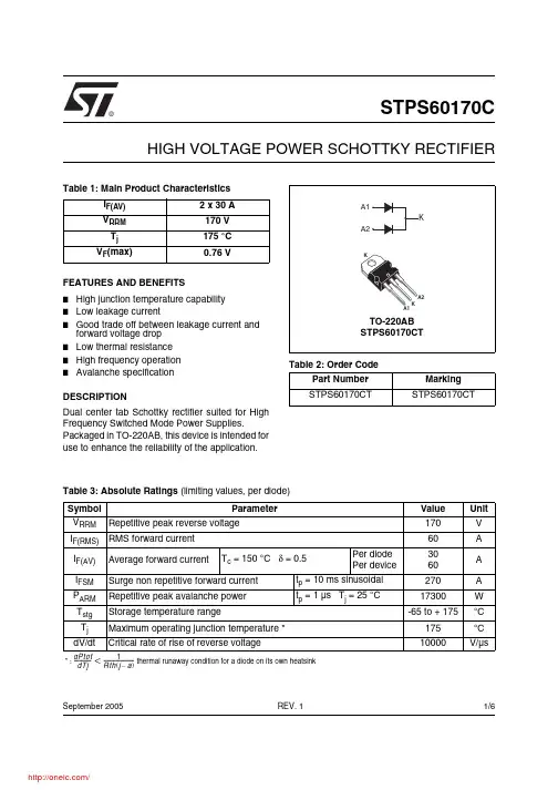
®1/6Table 1: Main Product CharacteristicsI F(AV) 2 x 30 A V RRM 170 V T j 175 °C V F (max)0.76 VSTPS60170CHIGH VOLTAGE POWER SCHOTTKY RECTIFIERREV. 1September 2005FEATURES AND BENEFITS■High junction temperature capability ■Low leakage current■Good trade off between leakage current and forward voltage drop ■Low thermal resistance ■High frequency operation ■Avalanche specificationDESCRIPTIONDual center tab Schottky rectifier suited for High Frequency Switched Mode Power Supplies.Packaged in TO-220AB, this device is intended for use to enhance the reliability of the application.Table 2: Order CodePart Number Marking STPS60170CTSTPS60170CTTable 3: Absolute Ratings (limiting values, per diode)Symbol ParameterValue Unit V RRM Repetitive peak reverse voltage 170V I F(RMS)RMS forward current 60A I F(AV)Average forward currentT c = 150 °C δ = 0.5Per diode Per device3060A I FSM Surge non repetitive forward current t p = 10 ms sinusoidal 270A P ARM Repetitive peak avalanche power t p = 1 µs T j = 25 °C17300W T stg Storage temperature range-65 to + 175°C T j Maximum operating junction temperature *175°C dV/dtCritical rate of rise of reverse voltage10000V/µs* : thermal runaway condition for a diode on its own heatsink dPtot dTj---------------1Rth j a –()-------------------------<STPS60170C2/6Table 4: Thermal Parameters Table 5: Static Electrical Characteristics (per diode)Pulse test:* tp = 5 ms, δ < 2%** tp = 380 µs, δ < 2%To evaluate the conduction losses use the following equation: P = 0.60 x I F(AV) + 0.053 I F 2(RMS)Symbol ParameterValue Unit R th(j-c)Junction to casePer diode Total 1.00.7°C/WR th(c)Coupling0.4When the diodes 1 and 2 are used simultaneously:∆ Tj(diode 1) = P(diode 1) x R th(j-c)(Per diode) + P(diode 2) x R th(c)Symbol ParameterTests conditions Min.Typ Max.Unit I R *Reverse leakage currentT j = 25 °C V R = V RRM35µA T j = 125 °C 835mAV F **Forward voltage dropT j = 25 °CI F = 30 A0.94VT j = 125 °C 0.720.76T j = 25 °C I F = 60 A0.97 1.05T j = 125 °C0.860.92STPS60170C3/6Figure 1: Average forward power dissipation versus average forward current (per diode)Figure 2: Average forward current versus ambient temperature (δ = 0.5, per diode)Figure 3: Normalized avalanche power derating versus pulse durationFigure 4: Normalized avalanche power derating versus junction temperatureFigure 5: Non repetitive surge peak forward current versus overload duration (maximum values, per diode)Figure 6: Relative variation of thermal impedance junction to case versus pulse durationTd =t /Tt pTd =t /Tt ptTd =t /Tt pSTPS60170C4/6Figure 7: Reverse leakage current versus reverse voltage applied (typical values, per diode)Figure 8: Junction capacitance versus reverse voltage applied (typical values, per diode)Figure 9: Forward voltage drop versus forward current (per diode, low level)Figure 10: Forward voltage drop versus forward current (per diode, high level)STPS60170C5/6Figure 11: TO-220AB Package Mechanical DataIn order to meet environmental requirements, ST offers these devices in ECOPACK® packages. Thesepackages have a Lead-free second level interconnect . The category of second level interconnect is marked on the package and on the inner box label, in compliance with JEDEC Standard JESD97. The maximum ratings related to soldering conditions are also marked on the inner box label. ECOPACK is an ST trademark. ECOPACK specifications are available at: .Table 6: Ordering Information■Epoxy meets UL94, V0■Cooling method: by conduction (C)■Recommended torque value: 0.55 Nm.■Maximum torque value: 0.7 Nm.Ordering type Marking Package Weight Base qtyDelivery mode STPS60170CTSTPS60170CTTO-220AB2.20 g50TubeTable 7: Revision HistoryDate RevisionDescription of Changes16-Sep-20051First issue.STPS60170CInformation furnished is believed to be accurate and reliable. However, STMicroelectronics assumes no responsibility for the consequences of use of such information nor for any infringement of patents or other rights of third parties which may result from its use. No license is granted by implication or otherwise under any patent or patent rights of STMicroelectronics. Specifications mentioned in this publication are subject to change without notice. This publication supersedes and replaces all information previously supplied. STMicroelectronics products are not authorized for use as critical components in life support devices or systems without express written approval of STMicroelectronics.The ST logo is a registered trademark of STMicroelectronics.All other names are the property of their respective owners© 2005 STMicroelectronics - All rights reservedSTMicroelectronics group of companiesAustralia - Belgium - Brazil - Canada - China - Czech Republic - Finland - France - Germany - Hong Kong - India - Israel - Italy - Japan - Malaysia - Malta - Morocco - Singapore - Spain - Sweden - Switzerland - United Kingdom - United States of America6/6分销商库存信息: STMSTPS60170CT。

This document was generated on 08/21/2012PLEASE CHECK FOR LATEST PART INFORMATIONPart Number:71741-2002Status:ActiveOverview:PMCDescription:1.00mm Pitch Mezzanine Plug, Surface Mount, Dual Row, Vertical Stacking, 84Circuits, 6.35mm Unmated Height, without PCB Locator Pegs, with Robotic Placement Metal Cap, 0.76µm Gold (Au) Selective Plating, Embossed Tape oDocuments:3D ModelProduct Specification PS-71741-9999 (PDF)Drawing (PDF)RoHS Certificate of Compliance (PDF)Agency CertificationCSA LR19980ULE29179GeneralProduct Family PCB Headers Series71741Application Board-to-Board, Signal OverviewPMCProduct Name Mezzanine UPC756054216941PhysicalBreakawayNo Circuits (Loaded)84Circuits (maximum)84Color - Resin Natural Flammability94V-0Glow-Wire Compliant No Lock to Mating Part NoneMated Height 13.00mm, 8.00mm Material - MetalPhosphor Bronze Material - Plating MatingGold Material - Plating Termination TinMaterial - Resin High Temperature Thermoplastic Net Weight1.460/g Number of Rows 2Orientation Vertical PCB Locator No PCB Retention NonePackaging TypeEmbossed Tape on Reel Pitch - Mating Interface 1.00mm Plating min - Mating0.762µm Plating min - Termination 1.905µmRobotic Placement Pick and Place Cap Shrouded Fully StackableNoTemperature Range - Operating -55°C to +85°C Termination Interface: StyleSurface Mount ElectricalCurrent - Maximum per Contact 1A Voltage - Maximum100VSolder Process DataLead-free Process CapabilityReflow Capable (SMT only)Seriesimage - Reference onlyEU RoHSChina RoHSELV and RoHS Compliant REACH SVHC Not ReviewedLow-Halogen Status Not ReviewedNeed more information on product environmental compliance?Email productcompliance@For a multiple part number RoHS Certificate of Compliance, click herePlease visit the Contact Us section for any non-product compliance questions.Search Parts in this Series 71741SeriesMates With71742 for Stack Height 10.00mm, 71742 for Stack Height 15.00mmProcess Temperature max. C260Material InfoReference - Drawing NumbersProduct Specification PS-71741-9999Sales Drawing SDA-71741-2***This document was generated on 08/21/2012PLEASE CHECK FOR LATEST PART INFORMATION分销商库存信息: MOLEX 0717412002。
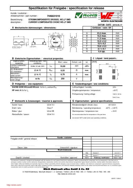
description :Gehäuse / case: SHA 23,3 max.mmB 18,5 max.mmC 11,5 max.mmD 10,0 ± 0,2mmE 5,0 ± 0,2mmF 19,6 ± 0,3mmG 2,1 ± 0,1mm H0,4 typ.mmEigenschaften / propertiesWert / valueEinheit / unittol.Leerlauf-Induktivität /inductanceDC-Widerstand /DC-resistance Nennstrom /rated current Nennspannung /rated voltage33%+20°CPrüfspannung / testing voltage1500 V, 50 Hz 5mA, 2 sec.SBaVersion 22010-05-17BKo Version 12009-02-17NameÄnderung / modificationDatum / dateÜbertemperatur / temperature rise: < 55 KKlimabeständigkeit/ climatic class: 40/125/21.............................................................Datum / dateCURRENT-COMPENSATED CHOKE WE-LF SMDmH R DC WAYNE KERR WK3260B/WK3265für/for L 0 und/and R DC U NI N Luftfeuchtigkeit / humidity:Class F Betriebstemp. / operating temperature: -40°C - +125°C HP 34401 A für/for I N...............................................................................0,70max.0,55±30%B Elektrische Eigenschaften / electrical properties:25050 HzUnterschrift / signatureKontrolliert / approvedWürth Elektronik.................................................................................................................................................................DATUM / DATE : 2010-05-17max.A Testbedingungen / testconditionsVΩA Mechanische Abmessungen / dimensions :10 kHz / 0,1 mA / 20°CC Lötpad / land pattern.:Umgebungstemperatur / temperature:L O 10,00D Prüfgeräte / test equipment:E Testbedingungen / test conditions:@ 20 °C @ 70 °C UL94 HB It is recommended that the temperature of the part does not exceed 125°C under worst case operating conditions.G Eigenschaften / general specifications:Sockel / base:Draht / wire:UL94 V-0F Werkstoffe & Zulassungen / material & approvals:Kleber / glue:Freigabe erteilt / general release:Kunde / customerAbstandhalter / spacer:UL94 V-0Würth Elektronik eiSos GmbH & Co. KGGeprüft / checked This electronic component is designed and developed with the intention for use in general electronics equipments. Before incorporating the components into any equipments in the field such as aerospace, aviation, nuclear control, submarine, transportation, (automotive control, train control, ship control), transportation signal, disaster prevention, medical, public information network etc. where higher safety and reliability are especially required or if there is possibility of direct damage or injury to human body.In addition, even electronic component in general electronic equipments, when used in electrical circuits that require high safety, reliability functions or performance, the sufficient reliability evaluation-check for the safety must be performed before use. It is essential to give consideration when to install a protective circuit at the design stage.[mm]description :SBaVersion 22010-05-17BKoVersion 12009-02-17NameÄnderung / modificationDatum / dateH Einfügungsdämpfung / insertion loss:Freigabe erteilt / general release:Geprüft / checked Kontrolliert / approvedDatum / dateWürth ElektronikWürth Elektronik eiSos GmbH & Co. KG.................................................................................................................................................................CURRENT-COMPENSATED CHOKE WE-LF SMDDATUM / DATE : 2010-05-17Unterschrift / signature ............................................................................................................................................Kunde / customer01020304050600,010,1110E i n f üg u n g s d äm p f u n g / i n s e r t i o n l o s s [d B ]Frequenz / frequency [MHz]typischer Dämpfungsverlauf / typical attenuation curveThis electronic component is designed and developed with the intention for use in general electronics equipments. Before incorporating the components into any equipments in the field such as aerospace, aviation, nuclear control, submarine, transportation, (automotive control, train control, ship control), transportation signal, disaster prevention, medical, public information network etc. where higher safety and reliability are especially required or if there is possibility of direct damage or injury to human body.In addition, even electronic component in general electronic equipments, when used in electrical circuits that require high safety, reliability functions or performance, the sufficient reliability evaluation-check for the safety must be performed before use. It is essential to give consideration when to install a protective circuit at the design stage.description :Gurtspezifikation / Tape specification:A24mmB4mmC44mma330 ± 2,0mmb21 ± 0,8mmc13 ± 0,5mmd150 ±1,0mme48,4mmf44mm165 to 180°SBa Version 22010-05-17BKo Version 12009-02-17NameÄnderung / modification Datum / date Datum / date Unterschrift / signatureWürth Elektronik.............................................................Geprüft / checked Kontrolliert / approvedWürth Elektronik eiSos GmbH & Co. KGI Rollenspezifikation / tape and reel specification:Rollenspezifikation / Reel specification: Freigabe erteilt / general release:Kunde / customer..................................................................................CURRENT-COMPENSATED CHOKE WE-LF SMDDATUM / DATE : 2010-05-17............................................................................... ...............................................................................The force for tearing off cover tape is10 to 130 grams in arrow directionfeeding directionØ ca b dA BefCThis electronic component is designed and developed with the intention for use in general electronics equipments. Before incorporating the components into any equipments in the field such as aerospace, aviation, nuclear control, submarine, transportation, (automotive control, train control, ship control), transportation signal, disaster prevention, medical, public information network etc. where higher safety and reliability are especially required or if there is possibility of direct damage or injury to human body.In addition, even electronic component in general electronic equipments, when used in electrical circuits that require high safety, reliability functions or performance, the sufficient reliability evaluation-check for the safety must be performed before use. It is essential to give consideration when to install a protective circuit at the design stage.分销商库存信息: WURTH-ELECTRONICS 7446631010。
