力科示波器使用手册
- 格式:pdf
- 大小:852.02 KB
- 文档页数:8

820-2StroboscopeUsers ManualSeptember 2014© 2014 Fluke Corporation. All rights reserved. Specifications are subject to changewithout notice. All product names are trademarks of their respective companies.LIMITED WARRANTY AND LIMITATION OF LIABILITY This Fluke product will be free from defects in material and workmanship for two years from the date of purchase. This warranty does not cover fuses, disposable batteries, or damage from accident, neglect, misuse, alteration, contamination, or abnormal conditions of operation or handling. Resellers are not authorized to extend any other warranty on Fluke’s behalf. To obtain service during the warranty period, contact your nearest Fluke authorized service center to obtain return authorization information, then send the product to that Service Center with a description of the problem.THIS WARRANTY IS YOUR ONLY REMEDY. NO OTHER WARRANTIES, SUCH AS FITNESS FOR A PARTICULAR PURPOSE, ARE EXPRESSED OR IMPLIED. FLUKE IS NOT LIABLE FOR ANY SPECIAL, INDIRECT, INCIDENTAL OR CONSEQUENTIAL DAMAGES OR LOSSES, ARISING FROM ANY CAUSE OR THEORY. Since some states or countries do not allow the exclusion or limitation of an implied warranty or of incidental or consequential damages, this limitation of liability may not apply to you.Fluke CorporationP.O. Box 9090 Everett, WA 98206-9090 U.S.A. Fluke Europe B.V. P.O. Box 1186 5602 BD Eindhoven The Netherlands11/99Table of ContentsTitle Page Introduction (1)How to Contact Fluke (1)Safety (2)Symbols (3)Standard Equipment (4)Features (5)Auto Off (8)Low-Battery Indicator (8)Product Use (9)Default Settings (9)Setup Menu (10)Range (10)External Trigger (11)Maintenance (11)How to Clean the Product (12)How to Change the Batteries (12)Specifications (14)Mechanical Specifications (14)Environmental Specifications (14)Miscellaneous Specifications (16)i820-2Users ManualiiList of TablesTable Title Page1. Symbols (3)2. The Product (6)3. Display (7)List of FiguresTitle Page Figure1. The Product (5)2. External Trigger Connector Polarity (11)3. Battery Replacement (13)iii820-2Users ManualivIntroductionThe 820-2 Stroboscope (the Product) uses an adjustable LED strobe light to show the movement of mechanical parts. The frequency range is 30 flashes per minute (FPM) to 300,000 FPM.How to Contact FlukeTo contact Fluke, call one of the following telephone numbers:•Technical Support USA: 1-800-44-FLUKE(1-800-443-5853)•Calibration/Repair USA: 1-888-99-FLUKE(1-888-993-5853)(1-800-363-5853)1-800-36-FLUKE• Canada:•Europe: +31 402-675-200+81-3-6714-3114• Japan:+65-6799-5566• Singapore:•Anywhere in the world: +1-425-446-5500Go to to register your product, download manuals, and find more information.To view, print, or download the latest manual supplement, visit /usen/support/manuals.1820-2 Users Manual2SafetyA Warning identifies conditions and procedures that are dangerous to the user.WarningTo prevent possible personal injury:•Read all safety information before you use the Product. •Carefully read all instructions. • Use the Product only as specified, or the protection supplied by the Product can becompromised.• Do not touch the moving target object when you use the Product. In stroboscopic light, objectmovement can appear still or slowed.• Do not use the Product around explosive gas, vapor, or in damp or wet environments.• Do not use the Product around personnel that are susceptible to epileptic seizures.•Do not use the Product if it is damaged.Stroboscope Symbols 3SymbolsSymbols used in the manual or on the Product are shown in Table 1.Table 1. Symbols Symbol DefinitionRisk of danger. Important information. See manual.BatteryConforms to relevant Australian EMC standards.Conforms to European Union directives. Conforms to relevant South Korean EMC Standards.This product complies with the WEEE Directive(2002/96/EC) marking requirements. The affixed labelindicates that you must not discard thiselectrical/electronic product in domestic householdwaste. Product Category: With reference to theequipment types in the WEEE Directive Annex I, thisproduct is classed as category 9 "Monitoring andControl Instrumentation" product. Do not dispose ofthis product as unsorted municipal waste. Go toFluke’s website for recycling information.820-2 Users Manual4 Standard EquipmentIf an item below is missing or damaged, contact Fluke. The Product comes with:• Quick Reference Guide• Safety Information• International Registration Card• Statement of Quality• Hard Case•AA Batteries (3) • External Trigger Input ConnectorFeaturesFeaturesFigure 1, Table 2, and Table 3 show the Product.Figure 1. The ProductUsers ManualTable 2. The ProductItem Description DisplayPower Button- Push to turn on the Product. Push and hold for 2 seconds to turn off the Product.Push to divide the current set value by two. The scroll speed increases when is continuously held down.External trigger connectionSetup- Push to move between different settings and modes.Push to double the current set value. Speed of the scroll increases when this button is held down.LED strobePush the trigger ( ) up to increase the current set value. Push down to decrease the current set value. Speed increases when is held down.Battery compartmentFeatures Table 3. DisplayUsers ManualTable 3. Display (cont.)Item Description Item DescriptionLow battery. Replacethe battery.1/min or RPM forexternal trigger input.Flashes per minute(FPM), default at powerup.Flashes per second.Adjustment isaccessed in the SetupMenu.Pulse delay in degrees(Phase degree).Adjustment isaccessed in the SetupMenu.Pulse delay inmilliseconds (ms).Adjustment isaccessed in the SetupMenu.Internal triggerAuto OffTo conserve battery power, the Product turns off after 15 minutes of non-use.Low-Battery IndicatorThe low-battery indicator is shown when the battery is low. When the low-battery indicator shows ( ), change the batteries.Product UseProduct UseThe subsequent sections tell you how to use the Product.Push to turn on the Product. Push and hold for 2 seconds to turn off the Product.Default SettingsTo set the Product to the default settings, push and hold and .The default settings are:FPM• 1000Hz• 16.7Pulseμs• 333• 2.0 Pulse deg•0 Delay ms•0 Phase deg•External pulse divider = 1•External trigger edge = 0 (positive)Users ManualSetup MenuWhen you push , the display shows the Setup menu. From the Setup menu, you can change these parameters:•Hz setting – Adjust the flashes per seconds in Hz.•Pulse width in μs ( ) – Adjust the flash intensity in microseconds of pulse width.•Pulse width in degrees ( ) – Adjust the flash intensity in degrees of flash rate.•Delay in ms ( ) – Adjust the delay time in milliseconds between internal trigger and flash. Precise adjustments of the observation position can be made with this setting.( ) – Adjust the degrees of phase shiftdegree• Phasebetween internal trigger and flash. Precise adjustments of the observation position can be made with this setting. •External trigger pulse divider ( ) – Set the external trigger divider, to adjust the flash rate.•External trigger edge ( ) – Set the external trigger edge to either positive (0) or negative (1).Push , , and to make adjustments to each parameter. Push to change parameters and to enter and exit the Setup menu.RangeWhen the external trigger is >5 kHz, -OL- shows on the display. When the external trigger is <0.5 Hz, -UL- shows on the display.Maintenance External TriggerUse the External Trigger Input Connector for outside trigger sources. When the Connector is plugged into the Product (see Figure 1, item ) the Product displays . Table 3 shows what options are available when an external trigger is used. For Connector polarity information, see Figure 2.-gsh04.eps Figure 2. External Trigger Connector PolarityMaintenanceCautionThe Product contains no user-serviceable parts. Toprevent damage to the Product, do not open thecase. For service, see “How to Contact Fluke”.Users ManualHow to Clean the ProductRegularly clean the case with a damp cloth and mild detergent.CautionTo prevent damage to the Product, do not useabrasives or solvents to clean the Product case.How to Change the BatteriesThe Product is energized by three AA (LR6) batteries. When the low battery symbol shows on the display ( ), replace the batteries. See Figure 3.CautionTo prevent damage to the Product:•Be sure that the battery polarity is correct toprevent battery leakage.•Remove batteries to prevent battery leakageand damage to the Product if it is not used foran extended period.MaintenanceFigure 3. Battery ReplacementUsers ManualSpecificationsMechanical SpecificationsSize (H x W x L) .................. 5.71 cm x 6.09 cm x 19.05 cm(2.25 in x 2.4 in x 7.5 in)Weight .... ............................ 0.24 kg (0.53 lb)Environmental SpecificationsOperating Temperature ....... 0°C to +45 °C (+32 °F to +113 °F)Storage Temperature .......... -10 °C to +50 °C (+14 °F to +122 °F)Operating Humidity .......... N on-condensing, < +50 °F (< +10 °C)90 %RH, +10 °C to +30 °C(+50 °F to +86 °F)75 %RH, +30 °C to +40 °C(+86 °F to +104 °F)45 %RH, +40 °C to +50 °C(+104 °F to +122 °F)Condensation) (WithoutAbsorption/Corrosion ........ +30 °C (+86 °F), 95 %RH, 5 daysProduct functions normallyOperating Altitude ............... 2,000 mStorage Altitude .................. 12,000 mVibration .............................. M IL-PRF-28800F Class 2StroboscopeSpecificationsSafety ................................. IEC 61010-1:Pollution Degree 2 ElectromagneticEnvironment ....................... IEC 61326-1:IndustrialGroup1 ISM equipment: group 1 contains all ISM equipment in which there is intentionally generated and/or used conductively coupled radio-frequency energy which is necessary for the internal functioning of the equipment itself.Class A equipment is suitable for use in non-domestic locations and/or directly connected to a low-voltage power supply network. Class A equipment may have potential difficulties in ensuring electromagnetic compatibility in other environments,due to conducted as well as radiated disturbances. ElectromagneticCompatibility ...................... Applies to use in Korea only.Class A Equipment (IndustrialBroadcasting & CommunicationEquipment) [1][1] This product meets requirements for industrial (Class A)electromagnetic wave equipment and the seller or user should takenotice of it. This Equipment is intended for use in businessenvironments and is not to be used in homes.15820-2 Users Manual16 Miscellaneous SpecificationsBattery Type ........................ 3 x AA Alkaline LR6 Flash FrequencyRange ............................. 30 FPM to 300,000 FPM 0.5 Hz to 5000 Hz Accuracy ........................ 0.02 %Resolution ....................... 30 FPM to 999 FPM = 0.11000 FPM to 300,000 FPM = 10.5 Hz to 999 Hz = 0.11000 Hz to 5000 Hz = 1 Frequency Setting .............. F PM or Hz Flash PulseDuration ........................ A djustable in μs or degreesDelay ............................. A djustable in ms or degrees Light Color ............................. A pprox. 6500 KEmission Output ........... 4800 lx @ 6000 FPM30 cm (11.9 in) at 3°External TriggerMethod .......................... C onnector to externally control triggerFrequency Range ......... 0.5 Hz to 5000 HzHigh Level ..................... 3 V to 32 VLow Level ..................... <1 V Minimum Pulse Width ... 50 μs Connection。
示波器探头基础系列之五——示波器探头使用指南美国力科公司概述:本文旨在帮助读者对常用的示波器探头建立一个基本认识。
此外,我们通过一系列的例子说明探头的不正确使用如何影响测量的结果。
理解探测问题注意!连接示波器和待测物会给被测波形带来失真。
示波器上应该贴上上面类似的警告标签吗?或许是的。
示波器同其它测量仪器一样,受制于各种测量问题——显然,示波器和待测物的连接会影响到测量,使用者理解这样的影响是非常重要的。
随着示波器技术的发展,连接示波器和待测物的工具和技术已经变得非常成熟。
早期的示波器,测量带宽只有几百KHz数量级,常使用电缆连接电路。
现代示波器使用各种连接技术以最小化测量误差。
使用者应该熟悉示波器本身以及示波器连接电路的各种方法的特性和限制。
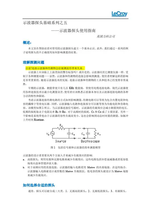
考虑示波器连接待测电路的方式如何影响测量,待测电路可以等效为包含内置电阻和电容的戴维宁等效电压源。
同样,示波器输入电路和连接部分可以被等效为负载电阻和旁路电容。
该模型如图1所示。
当示波器连接信号源时,示波器的负载效应会减小测量到的电压。
低频的损耗取决于电阻比率Rs和Ro。
对于高频时的损耗,Cs和Co成了主要因素。
另外一个影响是系统带宽由于示波器的容性负载而变小,这也会影响到动态时间量的测量,如脉冲上升时间Risetime。
图1 包括信号源和示波器的简单测量模型示波器的设计者需要从两个方面入手来减少负载效应的影响:a.高阻探头,利用有源和无源电路来减少负载效应,这些电路包括补偿衰减器或者低容值场效应晶体管缓冲放大器。
b.对于高频应用的直接连接,示波器的输入电路采用50ohm的内部端接。
在这些场合,示波器输入电路被设计成常数的50ohm负载阻抗。
低电容的探头被设计为50ohm端接来减少负载效应。
如何选择合适的探头通常,探头可以被分成三大类。
1、无源高阻探头;2、无源低阻探头;3、有源探头。
针对特定应用选择特定探头,这些探头的优点和缺点都需要被仔细考虑。
表1给出了三种探头以及它们适合的频响范围和输入电压。


January 2016 (Simplified Chinese)© 2016 Fluke Corporation. All rights reserved. Specifications are subject to change without notice.All product names are trademarks of their respective companies.123B/124B/125B Industrial ScopeMeter ®用户手册有限担保和有限责任Fluke 担保在正常使用和保养的情况下,其产品没有材料和工艺上的缺陷。
从寄送之日起,担保期为三年。
部件、产品修理和服务的担保期限为 90 天。
本担保仅限于 Fluke 授权零售商的原购买人或最终用户,并且不适用于一次性电池、电缆接头、电缆绝缘转换接头或 Fluke 认为由于误用、改装、疏忽、污染及意外或异常操作或处理引起的任何产品损坏。
Fluke 担保软件能依照功能规格正常运行 90 天,并且软件是记录在无缺陷的媒介上。
Fluke 并不担保软件毫无错误或在运行中不会中断。
Fluke 授权的零售商应仅对最终用户就新的和未使用的产品提供本担保,但无权代表Fluke 公司提供额外或不同的担保。
只有通过 Fluke 授权的销售店购买的产品或者买方已经按适用的国际价格付款才能享受 Fluke 的担保支持。
在一国购买的产品需在他国修理时,Fluke 有权向买方要求负担重大修理/零件更换费用。
Fluke 的担保为有限责任,由 Fluke 决定是否退还购买金额、免费修理或更换在担保期间退还 Fluke 授权服务中心的故障产品。
如需要保修服务,请与您就近的 Fluke 授权服务中心联系,获得退还授权信息;然后将产品寄至服务中心,并附上产品问题描述,同时预付运费和保险费(目的地离岸价格)。
Fluke 不承担运送途中发生的损坏。
示波器基础系列之八——关于示波器捕获信号的基本原则及基本操作步骤汪进进 美国力科公司深圳代表处很多初学示波器的工程师最关心的是“怎么让波形出来”,这时候我们一般都被教会了要用“AutoSet”键。
但如果AutoSet之后波形还是出不来,我们往往不知所措了; 或者是即使Auto Set能使波形出来,就可以往下进行测量和分析了吗? 只有很初级的工程师会用AutoSet,所以我们很低端示波器WaveJet系列设计的AutoSet反应速度全世界最快,按一下Auto Set,1秒左右就有波形出来。
但AutoSet不能保证信号被准确地高保真地捕获。
高保真地捕获信号是操作示波器的第一要著,否则再继续一些测量和分析就没有什么意义了。
为实现高保真地捕获信号,我们需要掌握设置示波器的一些基本原则。
捕获信号的基本原则是:第一,最小化量化误差; 第二,时刻警惕采样率; 第三,至少捕获感兴趣的一个周期的低频成分; 第四,在有些时候使用一些特别的获取模式或处理方法。
首先,我们要了解示波器的屏幕显示。
示波器是人机交互的工具,每一个操作会带来屏幕上显示的变化,这变化代表什么含义? 这是基础之基础呵。
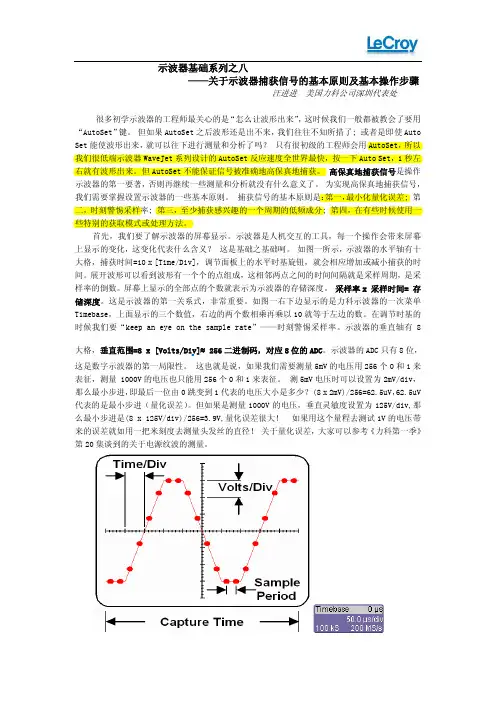
如图一所示,示波器的水平轴有十大格,捕获时间=10 x [Time/Div],调节面板上的水平时基旋钮,就会相应增加或减小捕获的时间。
展开波形可以看到波形有一个个的点组成,这相邻两点之间的时间间隔就是采样周期,是采样率的倒数。
屏幕上显示的全部点的个数就表示为示波器的存储深度。
采样率x 采样时间= 存储深度。
这是示波器的第一关系式,非常重要。
如图一右下边显示的是力科示波器的一次菜单Timebase,上面显示的三个数值,右边的两个数相乘再乘以10就等于左边的数。
在调节时基的时候我们要“keep an eye on the sample rate”——时刻警惕采样率。
示波器的垂直轴有8大格,垂直范围=8 x [Volts/Div]≈ 256二进制码,对应8位的ADC。
自定义示波器系列之一自定义示波器系列之一使用指南力科示波器MATLAB使用指南——力科示波器——美国力科公司 万力劢基于X-Stream技术的力科示波器既是一个高速信号采集平台,也是一个功能强大的信号处理平台。
示波器软件本身提供了丰富的测量和运算功能,能够满足常见的信号处理应用。
此外,力科示波器还能借助MATLAB及其丰富的函数、工具箱做更复杂、更个性化的实时信号处理。
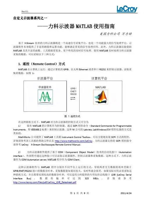
使用MATLAB实时处理力科示波器采集的数据,可以采取以下三种方式:遥控((Remote Control)方式1.遥控MATLAB在计算机上运行,通过计算机的GPIB、以太网Ethernet或者串口RS232来控制示波器、读取采集的数据,如图1:图 1 遥控方式在这种联机方式下,MATLAB对力科示波器的控制方式又可分为1)装有MATLAB的计算机作为控制器,通过SCPI程控命令(Standard Commands for Programmable Instruments,即IEEE488.2标准)来控制示波器。
这和NI公司的Labview, LabWindows/CVI程控仪器的方式是类似的。
MathWorks公司提供了MATLAB工具箱Instrument Control Toolbox,可以方便地实现SCPI方式的程控。
详情请参考该工具箱的帮助文件以及/LeCroy。
力科示波器支持的SCPI程控指令请参考LeCroy X-Stream Oscilloscopes Remote Control Manual。
2)力科示波器软件提供了基于COM(Component Object Model)技术的自动化接口(Automation interface)。
外部程序通过这种接口可以读取示波器属性、控制示波器和采集数据。
这种方式下,力科示波器作为COM Automation server, MATLAB程序作为COM Client。
这种示波器软件与MATLAB程序分别在不同平台上运行的方式,导致两者交互数据的效率受限于GPIB/ENET/RS232接口的数据吞吐率。
力(Li)科DA18000AC差分放大器使用(Yong)说明书修(Xiu)订版A –2006年(Nian)6月Lecroy Corporation700 Chestnut Ridge Road Chestnut Ridge, NY 10977–6499Tel: (845) 578 6020, Fax: (845) 578 5985网(Wang)址质保力科包管这一示波器配件从发货之日起一年内能够在技术数据范围内正常使用和操作。
备件、更换部件和维修件保修90天。
在实施质保时,对保修期内返回客户效劳部或授权效劳中心的任何组件,力科可以选择维修或更换这些组件。
但是,其前提是力科在查抄后确定缺陷是由于工艺或材料引起的,而不是由于滥用、疏忽、变乱、工作条件异常或非授权效劳机构进行维修或改动导致的损坏所引起的。
客户应负责支付把产物返回效劳机构所需的运输费和保险费。
力科返回保内产物时会预付运输费。
这一质保代替所有其它明示或默示的质保,包罗但不限于任何默示的适销性、适合或适用于特定用途。
不管是否签约,力科对其导致的任何特定损掉、间接损掉或后续损掉概不负责。
© 2006年力科公司版权所有,侵权必究。
LeCroy, ActiveDSO, WaveLink, JitterTrack, WavePro, WaveMaster, WaveSurfer和Waverunner均为力科公司注册商标。
其它产物或品牌名称是各自持有者的商标或申请注册的商标。
本文中的信息代替此前所有版本。
技术数据如有变动,恕不另行布告。
制造商厂颠末ISO 9000质量办理体系认证。
如需查看证书,请拜候。
本电子产物应按照各个国家和地域规定的不同法规进行回收和处置。
许多国家禁止以尺度废品回收方式处置废弃的电子设备。
如需了解与正确处置和回收力科产物有关的更多信息,请拜候。
DA18000AC-OM-E Rev A914190-00 Rev A一致性声(SHENG)明根(Gen)据ISO/IEC Guide 22和(He)EN 45014:1998 制造(Zao)商名称:力(Li)科公司制造商地址:700 Chestnut Ridge RoadChestnut Ridge, NY 10977USA特此声明:产物名称:差分探头型号:DA18000AC包罗所有选件在内,均符合下述欧盟指令条款,包罗最新修正内容及实施这些指令的国家司法解释:73/23/EEC低压指令89/336/EEC EMC指令符合欧盟73/23/EEC指令基于EN 61010-1: 2002测控和尝试室使用的电气设备安然要求符合欧盟89/336/EEC指令基于EN 61326/A3:2003 测控和尝试室使用的电气设备EMC要求辐射EN 55011/A2:2002 传导辐射和放射辐射抗扰度EN 61000-4-2/A2:2001 静电放电EN 61000-4-3/A1:2003 RF放射电磁场声明人:Scott Bausback 欧洲联系方法:首席运营官力科当地发卖处事处或地址:力科公司LeCroy Europe GmbH 700 Chestnut Ridge RoadWaldhofer Str 104Chestnut Ridge, NY 10977D-69123 HeidelbergUSAGermany日(Ri)期:2006年6月(Yue)12日:(49) 6221 82700:(49) 6221 834655警告:这是A级产物。
SDA3 Step by Step设置水平参数-获得足够的采样点2、调节timebase,满足采样点的要求 1.固定采样率,保证足够的采样率第2页设置垂直参数尽量占满整个屏幕,充分利 用ADC的8bit分辨率使用可变增益调节垂直刻度第3页进入SDAIII第4页SDAIII界面Step1: 打开SDAIII Step2: 打开4个通道中的任意一个或多个第5页输入信号设置Step1: 选择输入信号源Step2: 选择信号类型第6页CDR设置Step1: 计算信号速率Step2: 设置PLL第7页进入眼图测试菜单Step1: 打开眼图测试Step2: 显示眼图第8页眼图模板显示Step1: 选择眼图模板类型Step2: 显示眼图模板第9页眼图相关测量参数Step2: 眼图参数测量结果Step1: 选择眼图测量参数第10页眼图MarginStep1: 调整眼图模板的X和Y方向,验证眼图的MarginISOBERISOBER可以推算出更多样本时的眼图张开度眼图Fail定位Step1: 定位触碰模板的每一个bit位进入抖动测试菜单Step1: 打开抖动测试抖动测试结果Step2: 选择抖动参数Step1: 选择抖动分析模型,频谱分析方法结果与其他品牌示波器结果相似,NQ-Scale方法与BERT结果相似浴盆曲线Step2: 选择浴盆曲线、直方图等Step1:选择抖动直方图抖动频谱分析-Pj来自于哪些频率抖动的频谱可以缩放,可标注抖动峰值的频率Step1:显示Rj和BUj的频谱在抖动频谱分析中可以查找周期性抖动的来源Step2: 显示峰值码型分析分析ISI jitter进入噪声分析界面噪声参数结果Step3:Step1: 选择噪声分析模型,Step2: 选择噪声参数噪声直方图Step1: 选择噪声直方图Step2: 选择随机噪声直方图噪声频谱分析 - Pn来自于哪些频率噪声的频谱可以缩放,可标注抖动峰值的频率Step1:显示Rn和BUn的频谱在噪声频谱分析中可以 查找周期性噪声的来源Step2: 显示峰值第21页噪声追踪-查看噪声时域变化规律Step1: RnBUn的追踪第22页串扰眼图-查看在更低误码率下噪声的影响Step1: 显示串扰眼图Step2: 设置误码率第23页串扰眼图对比Step1: 快速对比任意两个 通道的串扰眼图第24页参考通道Step1:将任意一个通道保存 为参考,方便对比第25页LaneScape 对比模式可以选择1个/2个或所有 通道结果对比第26页谢谢关注!。
引言 (9)安全要求 (10)安全符号和术语 (10)工作环境 (10)冷却要求 (11)AC电源 (11)电源和接地连接 (13)校准 (13)清洁 (13)异常情况 (13)病毒保护 (14)在交付示波器时 (15)检查已经获得一切项目 (15)质保 (15)维护协议 (15)W INDOWS®许可协议 (15)L E C ROY®X-S TREAM软件最终用户许可协议 (15)安装和开机 (15)开机 (15)软件 (16)添加新选件 (16)恢复软件 (16)重启应用程序 (16)探头 (17)使用前面板控制功能 (18)垂直控制功能 (19)水平控制功能 (20)采集模式 (20)触发控制功能 (20)A UTO S ETUP按钮 (21)测量、缩放和数学运算快速按钮 (21)光标旋钮和按钮 (21)调节旋钮 (22)打印按钮 (22)清除扫描 (22)触摸屏 (22)辉度/采集模式 (22)了解显示信息 (23)顶部菜单栏(“F ILE”菜单) (23)网格区域 (24)触发延迟指示符 (24)触发电平指标符 (25)零电平指示符 (25)描述符标签 (25)消息栏 (26)通过不同方式完成同一操作 (27)顶部菜单栏 (27)鼠标和键盘操作 (27)显示信号—垂直设置 (27)启动通道 (27)耦合 (28)偏移校正 (28)探头衰减 (29)带宽限制 (29)平均信号 (29)内插设置 (29)噪声滤波(ERES) (29)使用工具栏快捷方式 (29)触发 (31)概述 (31)触发术语 (31)触发设置 (32)触发延迟 (32)触发电平指示符 (32)设置边沿触发 (33)触发抑制 (35)SMART T RIGGERS (36)标准SMART Trigger (36)可选的SMART Trigger (36)使用光标进行测量 (37)概述 (37)启动光标 (37)光标类型 (37)Horizontal (Time) (37)Vertical (Amplitude) (37)Horizontal (Frequency) (38)改变光标类型 (38)跟踪光标 (38)读取光标信息 (39)描述符标签 (39)光标表 (39)使用参数进行测量 (39)概述 (39)设置参数 (40)了解参数显示 (41)参数显示格式 (41)状态符号 (41)参数门(W INDOWS) (42)测量统计 (42)关闭参数 (43)缩放通道 (44)概述 (44)创建缩放 (44)触摸屏缩放 (44)前面板QuickZoom按钮 (45)工具栏缩放 (45)缩放描述符标签 (45)调节缩放标度和位置 (46)使用前面板控制功能 (46)使用缩放菜单控制功能 (46)使用工具栏快捷方式 (47)使用数学运算轨迹 (48)概述 (48)数学函数介绍 (48)标准数学运算 (48)MathSurfer高级数学运算 (48)设置数学运算轨迹 (50)数学运算描述符标签 (52)缩放数学运算 (52)使用数学运算菜单缩放控制功能 (53)工具栏快捷方式 (53)使用波形快速查看模式 (54)调节轨迹辉度 (54)保存和调用设置 (55)概述 (55)作为设置文件保存示波器设置 (55)从设置文件中调用示波器设置 (55)调用默认示波器设置 (55)保存和调用波形 (56)概述 (56)内存 (参考波形) (56)波形数据 (56)屏幕图 (56)保存和调用内存 (56)最快速的存储和显示方式 (56)使用内存工具栏快捷方式 (57)保存和调用波形数据 (58)保存波形数据 (58)调用波形数据 (59)保存屏幕图 (59)把屏幕图保存到文件中 (60)作为电子邮件附件发送屏幕图 (61)把屏幕图打印到打印机上 (61)把屏幕图保存到剪切板上 (62)与别人共享数据及交流 (63)概述 (63)连接到网络上 (63)进入桌面 (64)从示波器发送电子邮件 (64)注释图像文件 (64)在波形上创建标签 (64)保存数据文件和图像 (65)创建参考波形(内存) (65)打印 (65)远程控制和查看 (66)打印管理 (66)设置打印机 (66)打印 (66)添加打印机和驱程 (66)改变默认打印机 (67)通过/未通过测试 (67)概述 (67)模板测试 (67)操作 (67)设置通过/未通过测试 (67)设置模板测试 (68)辅助工具和首选项 (69)概述 (69)状态 (69)进入状态对话框 (69)远程通信 (69)设置远程通信 (69)配置Remote Control Assistant事件日志 (69)辅助输出 (70)设置辅助输出 (70)日期和时间 (70)手动设置时间和日期 (70)从互联网设置时间和日期 (70)从Windows设置时间和日期 (71)选项 (71)保养 (71)显示W INDOWS桌面 (72)触摸屏校准 (72)首选项 (72)声音反馈 (72)自动校准 (72)偏置控制 (72)本地语言 (73)偏置/延迟控制 (73)电子邮件 (73)采集状态 (73)远程控制操作 (75)标准 (75)程序消息 (75)自动化 (76)标准 (76)系统恢复 (77)恢复程序 (77)激活Windows (80)空白页引言本简要指南包括与WaveSurfer Xs系列示波器有关的重要的安全和安装信息,并包括示波器基本操作使用的简单操作程序。
⼒科⽰波器WaveSurfer基本操作第1页WaveSurfer⽰波器的基本操作StepbyStep第2页⽬录垂直功能设置触发设置⽔平设置⽰波器存档功能怎样保存测试结果的图⽚怎样保存和调⽤测试波形的数据怎样保存和调⽤⽰波器的设置测量参数设置其他功能长余辉游标第3页⽰波器垂直设置回到⽬录第4页⾯板调节垂直功能第5页通道设置点击即可直接设置通道1的多种设置或者点击Vertical->Channel1Setup…设置通道1回到⽬录第6页通道1的垂直设置菜单点击VariableGain后可以微调垂直刻度可以限制通道带宽回到⽬录第7页通道1的垂直设置菜单可以调节Deskew数值校准两个通道之间的skew,测量时序时可能会⽤到此功能可选择线性插值或者正弦插值回到⽬录第8页⽰波器触发设置回到⽬录第9页触发设置的两种⽅法点击菜单Trigger->TriggerSetup…点击屏幕右下⾓的trigger图标可直接设置触发回到⽬录第10页触发菜单触发设置菜单触发源C1DC耦合Edge边沿触发触发电平为0V回到⽬录第11页在WaveRunner⽰波器前⾯板设置触发功能回到⽬录第12页边沿触发的设置触发源为C1边沿触发触发电平,可以在⽰波器前⾯板Trigger->level旋纽调节边沿触发模式选择触发通道的耦合⽅式,通常使⽤DC耦合回到⽬录第13页智能触发的设置Step1:选择”Smart”TriggerStep2:可选择⽑刺触发Step3:选择触发源以及正/负边沿Step4:时间条件的设置触发的图⽰和说明回到⽬录第14页HDTV触发HDTV触发可选择TV制式回到⽬录第15页⽔平设置(时基设置)回到⽬录第16页⽔平设置的⼏种⽅法可以使⽤⽰波器前⾯板调节⽔平设置在菜单中调节⽔平设置点击触摸屏右下⾓图标可以直接调节⽔平设置回到⽬录测量中请随时注意采样率第17页⽔平设置:设定⽰波器存储深度回到⽬录Step1:点击设置TimebaseStep2:点击设置存储深度选择⽰波器波形的存储深度第18页保存测试结果的图⽚回到⽬录第19页打印图⽚的设置设置输出图⽚的格式回到⽬录第20页打印图⽚的设置打印图⽚的设置界⾯Step1:打印图⽚到⽂件Step2:选择输出⽂件的格式Step3:设置图⽚的颜⾊,三种颜⾊:彩⾊⿊底/彩⾊⽩底/单⾊Step4:打印图⽚的区域选择注明:已设置好“打印图⽚”格式的可以跳过此页!回到⽬录第21页设置图⽚的路径和⽂件名打印图⽚的设置界⾯Step1:编辑输出图⽚的⽂件名Step2:输出图⽚的保存路径输出图⽚的缩图回到⽬录第22页保存测试结果的图⽚在⽰波器前⾯板上按键即可保存⽰波器屏幕的图⽚在⽰波器软件中保存⽰波器图⽚回到⽬录第23页打印图⽚的⽂件名如上页所⽰按“Print”按钮后屏幕左下⾓会提⽰图⽚已保存继续按“Print”按钮,保存的图⽚的⽂件名后缀数字会⾃动增加转到WINDOWS界⾯中可以浏览保存的图⽚回到⽬录第24页保存和调⽤测试波形的数据回到⽬录第25页Step1:点击“SaveWaveform…”Step2:选择待保存的波形注:可以保存多种数据格式保存为Binary⽂件后可以调回到⽰波器分析Step3:编辑⽂件名Step4:设置⽂件的保存路径Step5:点击后保存波形⽂件到硬盘回到⽬录回调硬盘上的波形到⽰波器Step1:选择RecallWaveform…Step2:选择波形的⽂件路径和⽂件名点击可以打开⽂件浏览器Step3:选择⽂件调回的位置:M1/M2/M3/M4可选Step4:点击调回波形到⽰波器回到⽬录第27页保存和调⽤⽰波器的设置回到⽬录第28页保存和调⽤⽰波器设置Step1:点击SaveSetup…Step2:点击后输⼊设置的名字,然后点击Save保存设置到⽰波器内存或者可把设置保存到⽰波器的硬盘上回到⽬录第29页调⽤⽰波器内存中的设置Step1:点击RecallSetup…Step2:点击即可调⽤已保存的设置⽂件注:点击后回到⽰波器出⼚设置回到⽬录第30页调⽤⽰波器硬盘中的设置Step1:点击RecallSetup…Step2:点击后选择硬盘上的设置⽂件Step3:点击后完成调⽤测量参数设置回到⽬录第32页测量参数设置Step1:点击”MeasureSetup…”Step2:点击P1Step3:点击打开统计功能回到⽬录第33页Step1:点击设置参数⽔平测量参数测量参数的详细介绍Step2:点击切换为⼤图标模式回到⽬录第34页Step1:点击测量信号频率回到⽬录第35页垂直测量参数Step1:点击P2Step3:点击设置测量参数P2回到⽬录Step2:选择Vertical测量第36页Step1:选择Vertical测量Step2:测量信号的峰峰值回到⽬录完成P1,P2的参数设置第37页第38页余辉设置Step1:显⽰设置菜单Step2:激活余辉显⽰,选择模拟或彩⾊余辉Step3:余辉的保持时间为永久⾊彩饱和度设置回到⽬录第39页使⽤游标Step1:使⽤⽔平轴游标Step2:调节⾯板的cursor旋纽可以移动游标位置,或者直接⽤⿏标拖动此虚线游标测量结果使⽤其他游标回到⽬录第40页⾯板控制游标回到⽬录第41页TheEnd!。
Digital OscilloscopesWave r unner-2 Qu i c k s t a r t to Signal Vi e w i ngAnalo g Pe r s i s t e n c e ™Press A N A L O G P E R S I S T to access the power of An a l o g Pe r s i s t e n c e.The three-dimensional view shows va r i a tions in a wave f o r m as i n te n s i t y or co l o r -g r aded va ri ati o n s .Press D I S P L AY to custo m i z e the display.Press Z O O M for a close-up view of signal e the zoo m co n t r ols to magnify and inspe c t the signal,the soft k eys to change the zoom view,l o ck the zoom tra c es with multi-zoo m ,and to auto m a t i c ally scan the wave f o r m .1 .Co n n e c t your signal.When using a pro b e,Pro B u s ®a u t o m a t i c ally sets the ve r t i c al scale factor and HFP prob es a u t o m a t ic ally light-up with the tra c e co l o r .2 .Press A U T O S E T U P and view.3 .Press “ U n d o ”to reve r t back to a previous setting.Adjust the T I M E / D I V,and SMART Me mo r y a u t o m a t i c ally assure s the maximum re s o l u -tion for each time-base setting.Press a C H A N N E Lb u t t o n ,and use the co n t r ol knobs to s e l ec t and adjust that c h a n ne l ’s Vo l t s /D i v and offset settings.Press tw i c e to tog g l e the channel be t we e n On and Of f .Se l e c ts a pre- or po s t -t r igger e to v i e w the signal eve n t s p r ior to the tri g g e r po i n t.Presets the tri g g e r d e l a y to ze r o.Quick Zoo mPress a C H A N N E L b u t t on to viewthe menu.Wave p i l o t T Mfor Quick Me a s u r e m e n ts and An a l ysis with InsightPressW AVEP I L OT and M E A S U R E for a quick view of up to 26 standard p a r a m e t e r s ,to set up a custom para m e t e r ,or a pass/fail te s t .Se l e c t para m e t er measure m e n ts with statistics for multiple s w e e p s .1 .Se l e c t D A S H B O A R D for an exte n s i v e para m e t er set,or select standard Time or Voltage measure m e n t s .2 .The D A S H B O A R D v i e w is co n text sensitive so when youv i e w a signal,h i s t og r a m ,or Tra c k V i e w the measure m e n ts a r e re l e va n t.3 .C U S T O M t u r ns para m e t er statistics On or Off and allowsyou to define your own set of measure m e n t s .Pa r a m e t er Me a s u r e m e n t sMe a s u r e and An a l y z e Wave f o r m sFor math proce ssi n g ,Press button A,B,C ,or D to set up a zoo m t r a c e.1 .Press S E T U P2 .Se l e c t U S E M AT H and choose a funct i o n .Math and analysis can be pe r fo r med on any tra c e.Vi e w the result for tra c e A,B,C ,or D.Press A N A L O G P E R S I S T and select H I S T O R Y to maximize the upd a te rate and to display a signal in An a l o g Pe r s i s t e n c e and ins e q u e n c e mod e .Trigger time stamps for up to 4,000 acquisitions a r e displaye d .For further analysis of an acquisition segment,H i s t og r am the full Histo r y,then use P LAY and R EV E R S E to scan it in s e q u e n c e.Standard Measurementsa m p l Am p l i t u d ea r e a I n te g r al of wave f o r m dat ab a s e Lower of two most probable states cyc l e s cyc l e s Nu m b er of cycles of a pe r i o dic wave f o r m c m e a n Cyclic mean:The ave r age of wave f o r m dat a c r m s Cyclic root mean squard e l a y Time from trigger to tra n s i t i o n∆d l y Time be t ween 50% level of two source s d u t y Du t y cyc l e :Width as pe r ce n tage of pe r i o d f a l lFall time from 90% to 10%f 80-20%Fall time from 80% to 20%maximum The highest po i n t in a wave f o r m f r e q Fre q u e n c yminimum The lowest po i n t in a wave f o r m m e a n The ave r age of data for time-domain wave f o r m ove r +Ove r s h o ot po s i t i v e ove r -Ove r s h o ot negat i v e p k p k Pe a k -t o -p e a kpe r i o d Pe r i o d of a cyclic signalr 20-80%Rise time from 20% to 80%p h a s e Phase diffe r e n c e be t ween signal analyzed and ri s e Rise time from 10% to 90%signal used as a re f e r e n c es d e v St a n d a r d dev i a tion of data be t ween the cursors.rm s Root mean square of data be t ween the cursors w i d t hWidth of cyclic signal:All wave f o r m pulses to p Higher of two most probable state sa r e ave r aged then displaye dx a m n Ho r i z o n tal position of the smallest data va l u e x a m x The hori z o n tal position of the largest data va l u eWaverunner-2 Options:WAVA - WaveAnalyzer and EMM - Extended Math and Measurementc sde v Cyclic standard dev i a t i o n∆c2d±∆ clock to data ± (setup and hold time)cmedian Cyclic median:The ave r age of base and top∆t@lv The transition time be t ween selected levels on values over an inte g r al number of cyc l e sa single tra c e or be t ween two tra c e s f i r s t I n d i c ates value of hori z o n tal axis at left cursor m e d i a n The ave r age of base and top va l u e s l a s t Time from trigger to last (ri g h tmost) cursor po i n ts Nu mb er of po i n ts be t ween the cursors r @l e ve l Rise time be t ween selected voltage leve l s f @l e vel Fall time be t ween selected voltage leve l s dur Time be t ween triggers in segment /h i s t o r y modet @l e ve l Time from trigger (t=0) to crossing at a leve lStandard Math Tools (Signal Processing)Arithmetic Sum (add),Di f f e r e n c e (subtra c t ),Prod u c t (multiply),Ratio (divide)Ave r aging Summed ave r age of up to 4 000 swe e p s;Co n tinuous ave r age from 1:1 to 1:1024 we i g h t i n gExt r e m a Enve l o p e,f l o o r,and roo fF F T Fast Fo u r ier Tra n s f o r m to 50,000 po i n t s:FFT Ty p e s Power Spe c t r u m,P h a s e,Ma g n i t u d e.Wi n d o ws :Fl a t To p,Re c t a n g u l a r,Bl a c k man Ha r ri s,Von Ha n n,Ha m m i n gOther Fu n c t i o n s I d e n t i t y,Ne g a tion (Inve r t ),Sine x/xResample To deskew as well as resample signalsRe s c a l e Assign phys i c al units and re s c a l eE R E S En h a n c ed Resolution for up to 11 bits of ve r t i c al re s o l u t i o nWaverunner-2 Options:WAVA_WaveAnalyzerAll standard mat h,m e a s u r e m e n t,and signal processing tools plus:Extended Ave r aging Su m m e d.Ave r age of up to one million wave f o r m s.Co n tinuous ave r age from 1:1 to 1:1024 we i g h t i n gExtended FFT Fast Fo u r ier Tra n s f o r m to one million po i n t sFFT Ave r a g e,Power Ave r a g i n g,Re a l,Power De n s i t y,Real + ImaginaryH i s t og r a m s*Gra p h i c al analysis with Histog r ams and Histog r am An a l y sis Pa r a m e t e r sWAVA : 2 billion eve n t sE M M:200 eve n t sH i s t og r am Pa r a m e t e r sav g ave r age of data values in histog r a mf w h m full width (of largest peak) at half the maximum binf w x x full width (of largest peak) at xx% the maximum binh a m p l h i s t og r am amplitude be t ween two largest pe a k sh b a s e h i s t og r am base or leftmost of two largest pe a k sh i g h highest data value in histog r a mh m e d i a n median data value of histog r a mh r m s rms value of data in histog r a mhto p h i s t og r am top or ri g h tmost of two largest pe a k sl o w l o west data value in histog r a mm a x p po p u l a tion of most po p u l a ted bin in histog r a mm o d e d a ta value of most po p u l a ted bin in histog r a mpct l d a ta value in histog r am for which specified x% of po p u l a tion is smallerp k s n u m b er of peaks in histog r a mra n g e d i f f e r e n c e be t ween highest and lowest data va l u e ss i g m a s t a n d a r d dev i a tion of the data values in histog r a mto t p total po p u l a tion in histog r a mx a p k x-axis position of specified largest pe a kTrending* Plot a para m e t er versus time or versus another para m e t e rOther funct i o n s*Ab s o l u t e Va l u e,Re c i p r ocal (1/x),Sq u a r e,Sq u a r e Roo t,De r i v at i v e,I n te g r a l,Exp (base e),Exp (base 10),Log (base e), Log (base 10)DFP_Digital Filter PackageLinear-phase Fi n i t e Impulse Re s p onse (FIR) filte r s:Low Pa s s,High Pa s s,Band Pa s s,Band Sto p,Raised Co s i n e,Raised Root Co s i n e,Ga u s s i a nUp to 4 filters can be ca s c a d e d.Design a custom filter then download the filter coe f f i c i e n ts into the Wave P ro sco p e with DSOFi l t er utility.JTA_Jitter and Timing AnalysisJi t t e r T rack for a time co r re l a ted gra p h i c al view of cycle to cycle para m e t er va r i a t i o n.PMA1 – Power Measure AnalysisPower Me a s u r e An a l y sis provides para m e t r ic and gra p h i c al analysis of power dev i c e mod u l a tion and line power analys i s.* Also included with EMMWave r u n n e r - 2Tri g g e r i n gLevel indicato r sHo r i z o n tal delay (tri g g e r )position indicator I c ons indicate the ty p e and c h a r a c te r istics of the tri g g e rin use.Setup signal conditions Se l e c t pulse ty p e Se l e c t co u p l i n g Se l e c t trigger source Se l e c t trigger ty peNa meDe s c rip t i o nEd g e Se le c t po s i t i v e or negat i v e slope and hold-off by time or eve n t s .Wi n d o wSet a window around the trigger leve l .Trigger whenever the signal crosses outside the w i n d o w in either dire c t i o n .Waverunner-2 Basic TriggersAc c esses the trigger setupm e n u .Arms the tri g g e r .The sco p e triggers once when the triggerconditions are met and then displays the signal.Triggers even if a signal is notp r e s e n t.Triggers whenever the tri g g e r conditions are met.Sets the trigger leve l .Preve n ts the sco p e fro mt r i g g e r i n g .Flashes when a trigger oc c u r s .The text indicates stat u s .PressW AVE P I L OT and G RA P H for quick access to powe r ful pro b l e m solving fe a t u r e s .Qu i c k ly identify the problem with spe c i a l v i e ws :H i s t og r a m s ,F F T ,Tra c k V i e w,and Ji t t e r T ra c k .1 .Se l e c t the ty p e of view and the para m e t er or funct i o n .2 .Setup the view.3 .Se l e c t Graph and Tra c k V i e w or Ji t t e r T rack for a time- co r re l a ted view of measure m e n ts and you can visually t r ack down signal errors and anomalies.His t og r ams are fast and simple to set up.Press W AV E P I L OT a n d G RA P H ,dial in the measure para m e t e r ,s e l e c t the Histog r am Se t u p co n d i t i o n s ,then press A U T O S E T U P h i s t og r a m .Graph Pa r a m e t er Di s t r ibutions Get measure m e n ts that make sense! Press W AV E P I L OT and G RA P H ,then M E A S U R E ,for a quick,co n text -s e n s i t i v e para m e t er assess-m e n t of the chara c te r istics of Tra c k V i e ws.Graph andMe a s u r e m e n tsGraph Vi e wsRo t a r y co n t r o l s adjust the hori-zo n tal po s i t i o n and magnificat i o n of the selecte d zoom tra c e.Se l e c t a zoom tra c e fo r setup of signal proce s s -i n g .The analysis co n t r o l s a f f e c t the selected tra c e ( A ,B , C ,D ).Press tw i c e to toggle be t ween On and Of f .Quick Zooma u t o m a t i c ally displays 10X magnified tra c e s of all signals on multi-g r i d sProvides dire c t access to m a t h e m a t i c al signal p r oce s s i n g .An a l y sis Co n t r olsR S -232-CCe n t r onics co m p a t i b l e Pri n ter Po r tVGA Mo n i t or Po r tPC Ca r d Slot (optional)Su p p o r ts SRA M ,ATA Fl a s h ,a n d Ha r d Dri v e PC Ca r d s .50 Ω BNC Input for a 10 MHz Re f e r e n c e Cl o ckAC Line Input:Au t o m a t i c a l l y senses and co n f i g u r es line voltage and f r e q u e n c y.10 Base T Et h e r net Po r t (optional)Sales and Se r v i c eTh r oughout the Wo r l d Co r po r ate He a d q u a r te r s700 Chestnut Ridge Ro a d Chestnut Ri d g e ,NY 10977U S Aht t p ://w w w . l e c r oy. c o m Le C roy Sales Of f i c e s :Asia:Hong KongPhone (852) 2834 5630Fax (852) 2834 9893Austria:Markersdorf Phone (43) 2749 30050Fax (43) 2749 30051Benelux:The Netherlands Phone (31) 40 211 6998Fax (31) 40 211 6999France:Les UlisPhone (33) 1 69 18 83 20Fax (33) 1 69 07 40 42Germany:Heidelberg Phone (49) 6221 827 00Fax (49) 6221 834 655Italy:VenicePhone (39) 41 456 97 00Fax (39) 41 456 95 42Japan:OsakaPhone (81) 6 6396 0961Fax (81) 6 6396 0962Japan:TokyoPhone (81) 3 3376 9400Fax (81) 3 3376 9587Japan:TsukubaPhone (81) 298 56 0961Fax (81) 298 56 0962Korea:SeoulPhone (82) 2 3452 0400Fax (82) 2 3452 0490Spain:MadridPhone:(34) 91 640 11 34Fax:(34) 91 640 06 40Switzerland:Geneva Phone (41) 22 719 2111Fax (41) 22 719 2230U.K.:AbingdonPhone (44) 1 235 536 973Fax (44) 1 235 528796U.S.A.:Chestnut Ridge Phone (1) 845 578 6020Fax (1) 845 578 5985Co p y r i g h t © Ja n u a r y 2001Le C roy,Pro B u s ,and SMART Trigger are re g i s t e r ed tra d e m a r ks of Le C roy Co r po r at i o n .All ri g h ts re s e r ve d .Wave P ro,Wave r u n n e r ,L i t e r u n n e r ,Ji t t e r W i z a r d,Ji t t e r T ra c k ,Ji t t e r P ro,An a l o g Pe r s i s t e n c e,and Act i v eDSO are tra d e m a r ks of Le C roy Co r po r at i o n .I n f o r m a tion in this publication supersedes all earlier ve r s i o n s .Spe c i f i c ations subject to changewithout notice.Rear PanelTh r ee dimensional view a l l o ws va r i a tions in a wave f o r m as inte n s i t y or color graded va r i a t i o n s.。