GTS NX主要分析功能介绍
- 格式:pptx
- 大小:9.58 MB
- 文档页数:33


1 midas GTS背景介绍
midas GTS是北京迈达斯技术有限公司研发的岩土用软件,具有迈达斯软件专有优势:汉化界面、交互式操作、强大的可视化。
迈达斯技术有限公司由韩国浦项制铁发展而成的土木工程计算分析软件开发公司,具有独立的研发团队,并在中国、美国、日本、英国、印度、俄罗斯、新加坡等国家成立分公司。
北京迈达斯技术有限公司拥有一批国内研发团队,对软件再次“加工”,让midas 系列软件更加适合中国用户。
此外,北京迈达斯技术有限公司全面负责产品的销售与技术支持。
2 midas GTS功能介绍
midas GTS是为能够迅速完成对岩土及隧道结构的分析与设计而开发的“岩土隧道结构专用有限元分析软件”,是一款采用windows风格操作界面的完全中文化软件,能够提供完全的三维动态模拟功能。
程序提供应力分析、动力分析、渗流分析、应力-渗流耦合分析、边坡稳定分析、衬砌分析和设计功能,并提供莫尔库伦、修正莫尔库伦、邓肯-张、修正剑桥等14种本构及用户自定义本构模型;程序还提供便捷的几何建模功能、地形生成器、隧道建模助手、锚杆建模助手以及丰富的后处理结果;可以广泛应用于地下结构、岩土、水工、地质、矿山、隧道等方面的分析及科研。
自2005年在中国发布至今,在广大用户的信任和支持下,已经走过了九个年头,成为了岩土行业主流的分析与设计软件。
随着行业的发展,GTS也面临新技术的发展及完善,因此在2014年推出midas GTS NX(New Experience),分别在前处理、后处理及计算阶段进行了功能的改善,此外新增加了新的分析功能,具体见下表.
GTS NX功能一览表。
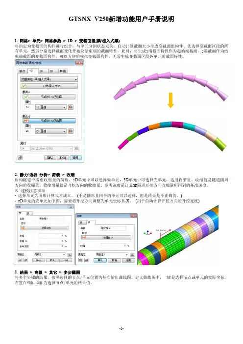
GTSNX V250新增功能用户手册说明1.网格>单元>网格参数>1D>变截面组(梁/植入式梁)将指定为变截面的构件进行组合,与单元分割状态无关,自动计算截面大小生成变截面组构件。
先选择变截面区段的所有单元,然后分别选择截面变化开始及结束端的截面特性。
此时,将生成i端截面特性作为起始端截面,j端截面作为结束端截面的变截面构件。
可以方便的模拟变截面构件,无需生成变截面区段各单元的截面特性。
2.静力/边坡分析>荷载>收缩盾构隧道中考虑收缩量的荷载。
2D单元中可以选择梁单元,3D单元中可选择壳单元,适用收缩量。
收缩值是隧道圆周方向的收缩量、收缩增量值是开挖方向的收缩量、参考深度是计算3D隧道开挖方向收缩量所用到的基准深度。
※建模注意事项-选择单元为圆形计算式才成立。
(不是圆形且闭合的单元可以选择,但是结果是不正确的。
)-3D单元的壳单元如下图,需要将开挖方向调整为单元坐标系-X。
(用于自动计算开挖方向的开挖宽度)3.结果>高级>其它>多步骤图将多个步骤的结果,按照选择的节点/单元位置为基准输出曲线图。
定义曲线图中,'轴'是选择节点或单元的实际坐标,布置在Y轴。
X轴为选择节点/单元的结果值。
4.网格>单元>界面:从桁架/梁(T/X-交叉型),从壳(T/X-交叉型)给T字形或X字形交叉的桁架/梁单元生成界面单元。
3D模型中可选择壳单元。
按照T字形或X字形生成界面单元,不能以桁架/梁单元,各自独立生成网格组(分别注册接触网格组)5.几何>曲面与实体>层面定义地层面建模助手中,通过导入Excel文件,定义地层面信息。
'输入'功能可以将多个钻孔信息一并导入。
地层面按平面名称,修正钻孔深度生成。
6.结果>特殊>渗流>流量能够更加简便地计算流量。
-增加了之前的节点选择方式及任意定义切割线/面的方式。

New eXperience ofGeoTechnical analysis SystemChapter 2Node/ DOF/ CoordinateSystemTABLE OF CONTENTSSection 1. Node and DOFSection 2. Coordinate SystemSection 3. Finite Rotation SimulationANALYSIS REFERENCESection 1. Node and DOF |9Chapter 2. Node/DOF/Coordinate systemNode and DOFNodes and elements determine the size and shape of the finite element model and are the starting point of all analyses. A model defined by nodes and elements is the same as physical phenomena expressed using numerical equations in matrix form. The variables that affect the matrix equation are displacement, rotation, pore pressure and other physical quantities, which are called degrees of freedom (DOF).For example, a structural analysis problem is assigned 3 displacements and 3 rotational DOFs. These 6 DOFs are as follows.Each DOF is generally expressed using the following signs:11DOF 1T u ==,22DOF 2T u ==, 33DOF 3T u==11DOF 4R θ==, 22DOF 5R θ==, 33DOF 6R θ==Each node has a coordinate system that describes the direction of motion. This is calledthe nodal displacement coordinate system. All DOFs mentioned above follow the coordinate system direction assigned to the nodes, and all nodes describe the direction of motion with reference to the global coordinate system. The pore pressure DOF does not have a direction and hence, it is unrelated to the nodal displacement coordinate system.2u 1u 3u 1θ3θ2θSection 1Figure 2.1.1 Displacement and Rotation DOFs on therectangular coordinate systemChapter 2. Node/DOF/Coordinate ANALYSIS REFERENCE10 | Section 2. Coordinate System Coordinate SystemVarious coordinate systems are needed to use the finite element method to appropriately model and correctly analyze the given problem. For example, a coordinate system is needed to define the nodal displacement direction outlined above and to set the direction for transversely isotropic materials. A particular coordinate system is also specified for result value extraction. The rectangular coordinate system and cylindrical coordinate system are both available on GTS NX.For example, if the nodal motion direction is defined about a cylindrical coordinate system, the DOFs are as follows.DOF 1 = translation in r-directionDOF 2 = translation in θ-directionDOF 3 = translation in z-directionDOF 4 = rotation in r-directionDOF 5 = rotation in θ-directionDOF 6 = rotation in z-directionGTS NX uses the following coordinate systems for ground or structural modeling and analysis.OriginzyxRectangularcoordinate systemzθrCylindricalcoordinate systemOriginSection 2Figure 2.2.1 Rectangular coordinate system and cylindrical coordinate systemANALYSIS REFERENCEChapter 2. Node/DOF/Coordinate systemSection 2. Coordinate System |11Type of coordinate systemExplanationGCS : global coordinate system Coordinate system that expresses the entiremodel using the same standard. Rectangularcoordinate systemNDCS : nodal displacement coordinatesystemCoordinate system that describes the nodalmotion direction. Rectangular/Cylindricalcoordinate systemECS : element coordinate system Coordinate system determined by the position ofthe nodes that make up the element. Rectangularcoordinate systemMCS : material coordinate system Coordinate system that defines the direction of thematerial applied on the element.Rectangular/Cylindrical coordinate systemERCS : element result coordinate system Coordinate system that prints the element results. Rectangular/Cylindrical coordinate systemEFCS : element formulation coordinatesystemCoordinate system used for finite elementformulation.Same as GCS or element coordinate systemHere, the EFCS is used in the solver and, although it may not be directly related to the instructions for the GTS NX, it provides a better understanding of the materials of this manual. Also, the MCS and ERCS can affect the analysis and results. Detailed information on the ECS, MCS and ERCS are provided in Chapter 3.yz y xGCSyxxzy xuv wTable 2.2.1 Major coordinate systems on the GTS NXFigure 2.2.2 Various coordinate systems on the GTS NXChapter 2. Node/DOF/CoordinateANALYSIS REFERENCE12 | Section 3. Finite Rotation SimulationFinite Rotation SimulationGeometric nonlinear analysis that includes finite rotation needs a variable for rotation. GTS NX uses the rotation vector as a DOF of a particular node to describe finite rotation. In other words, the result values for nodal DOF 4~6 on the geometric nonlinear analysis results are each components of the rotation vector. The rotation vector θ has a size θand direction /=e θθ. Expressing this in physical terms, the rotation vector θ rotates about the axis e by an angle θ (radian) as shown in Figure 2.3.1Be aware that a compound rotation, which applies multiple rotation vectors continuously, does not consist of the sum of each vector for finite rotations. For example, if a rotation of Δθis continuously applied after θ, the final rotation value *θhas a property of *≠+Δθθθ. Also, because the commutative law does not apply, applying Δθand θ in reversed order creates a different rotation value, as shown in figure 2.3.2. Various methods such as a rotation matrix can be used to calculate compound rotations, but the GTS NX uses the quaternion product. The quaternion q has the following relationship the rotation vector θ:0(,)(cos(/2),sin(/2))q q ==q θθe (2.3.1)The product of two quaternions can be calculated using the following equation:*0000(,)q q q q q q q =Δ=Δ−Δ⋅Δ+Δ+Δ×q q q q q q(2.3.2) zyx=θe θθAxis of rotationSection 3Figure 2.3.1 Direction and size of a rotation vectorANALYSIS REFERENCEChapter 2. Node/DOF/Coordinate systemSection 3. Finite Rotation Simulation |13*q : Quaternion corresponding to *θ qΔ: Quaternion corresponding to Δθ(90)°θ(90)°θ(90)Δ°θ(90)Δ°θInitial configuration Final configurationFigure 2.3.2 Example ofcompound rotations that do not satisfy the commutative law14 | Section 3. Finite Rotation Simulation。
midas gts nx模拟分析基坑开挖对周边建筑物沉降的影响盛勇飞摘要:超大超深基坑开挖过程中,无论基坑采取什么类型的支护方式,都很难避免其对周围临近建筑物的影响,使建筑物产生沉降或者开裂,严重时甚至倒塌。
本文主要以广州琶洲某地块基坑工程为例,采用midas gts nx模拟了基坑开挖及支护的整个过程,利用midas公司开发的大型岩土类三维有限元软件gts nx分析基坑开挖过程中既有建筑物沉降变形规律。
结果显示:随着基坑逐步开挖,临近建筑物沉降逐步加大,且建筑不同位置表现出离开挖面越近的地方沉降越大的特点,建筑物有向基坑边方向倾斜的趋势。
关键词:深基坑;开挖;支护;三维有限元;建筑沉降1、背景高层建筑的基础埋深一般较大,这对于增加建筑物的稳定性和充分利用地下空间是有利的。
但是,在城市建筑物密集地区,深基础给施工带来很多困难的同时也给周边建筑物安全提出了挑战,无论基坑采取何种支护方式,都很难做到使周边建筑物零沉降,因为基坑开挖过程是一个个逐步卸荷的过程,每开挖完一步,周围土体都会出现应力释放(包括土压力和水压力,为保证基坑开挖始终在地下水位以上及减小周边水压力,需要适度的降水),释放的应力时主要由基坑支护结构来承担,这样支护结构受力产生变形从而引起支护外面土体的位移和沉降,且离开挖面越远这种趋势越不明显,所以就造成周边建筑物的不均匀沉降,使建筑物产生次应力,可能改变结构的受力形式,如果超过建筑物原来的结构设计承载必然就会出现裂缝,进而影响建筑物的安全。
2、工程概述本基坑支护工程位于广州市天河区琶洲某地块,基坑呈标准长方形,长边约132.6m,短边约72.4m,开挖深度大部分为8m,局部塔楼区域10m,由于靠近珠江,支护结构采用C30混凝土连续墙,并用作止水帷幕,宽度1m,竖向设两道内支撑,钢筋混凝土内支撑截面均采用b×h=1000mm×900mm,基坑内支撑平面布置如图1所示。