Copley 驱动中文调试说明
- 格式:pdf
- 大小:1.43 MB
- 文档页数:84

DC swing gate operator,battery back-up & solar power• 115/230 V AC (switch selectable) input power or 24 VDC solar power • 1/2 HP quadra drive heavy-duty DC motor• S plit housing allows easy access without having to remove the gate arm• E asy to adjust electronic magnetic limits eliminate old style mechanical switches that can wear out, break or fail • H eavy-duty steel frame • 0.0 Amp SBPD circuit (solar power only)• S olar power ready • 5-Y ear limited warranty6524 VEHICULARAC/DC SWING GA TE OPERA TORACCESS CONTROL SOLUTIONSEasy to Operatemanual releaseRESIDENTIAL • COMMERCIALSteel Frame for strength and durabilityGate Tracker TMrecord users accessDC Motor & Battery Backupfor continued gate operation ifAC power is lostMECHANICALPrimary reduction is provided by a pulley / belt driving a 60:1 worm gear reduction system running in a continuous oil bathThe 6524 rotates the gate 90° in approximately12-14 secondsOperator mechanics are mounted on a steel frame plated for corrosion resistanceT wo-piece articulating arm mechanical slow-start /slow-stop functionMounting: operator requires a concrete mounting pad Keyed access is provided to release arm for manual gate operation in the event of a power outageSplit polypropylene housing simplifies installation and maintenance, no need to remove the gate armUnique breakaway hub helps to protect the gear box if the gate is rammedGATE TRACKER TMReporting output provides operator data to aDKS 1833, 1835, 1837 or 1838 access control system (requires 2358 expansion board)OPTIONS18 Ah batteries (operator includes two (2) 7.5 AhSLA batteries)Solar kit (Includes two 18 Ah batteries and10 watt, 24 VDC solar panel)ELECTRICALEasy adjustable electronic magnetic limit switchesAuto-close timer 1-30 secondsGate overlap feature for dual (bi-parting) gate operation Selectable shadow / reverse loop functionDC power shut-off switchBattery protection circuitPorts for plug-in open and reverse loop detectors.DKS plug-in detectors onlyAC Powered Operator Only115 V AC convenience outletsAC power shut-off switchMagnetic lock powerDC Powered Operator Only0.0 Amp SBPD PatPend circuit MISCELLANEOUSEnvironmental: 10°F to 115°F (-12°C to 46°C) Thermostatically controlled heater kit required for operation below freezing temperatures to prevent batteries from freezing. Heater kit can only be used with AC powered operatorsShipping weight approximately 175-225 lb (79-102 kg) depending on model and options selectedOperator requires monitored T ype B1 and/or T ype B2 entrapment protection devicesConforms T o ANSI/CAN/UL 325:2017 Ed. 7Certified T o CSA C22.2 #247DISTRIBUTED BY:MEMBER:DoorKing,® Inc.Access Control Solutions since 1948120 S. Glasgow Avenue,Inglewood, California 90301 U.S.A.Tel: 310-645-0023 FAX: 310-641-1586© 2020 All Rights Reserved.Product specifications maychange without notice. Rev. 6/20TECHNICAL FEATURES。

Quarter Master Chief Series 92 ActuatorInstallation, Operationand Maintenance ManualTable of ContentsSeries 92 Electric Actuator Introduction (3)Description (3)Electrical Requirement (3)Installation (4)Electrical (4)Type 21 Ball Valve (4)Type 23 Ball Valve (3-way) (5)Type 57 / 57L Butterfly Valves (5)Actuator Mounting Dimensions (6)Operation (7)Manual Override Operation (7)Setting Limit Switches (7)Options (8)Single Limit Switch (8)Double Limit Switch (8)Heater and Thermostat (8)Mechanical Brake (9)Feedback Potentiometer (9)Series 92 Options Codes for Serial # Tags (10)Troubleshooting (10)Maintenance (12)ATEX Requirements (12)Spare Parts (13)Series 92 Electric Actuator IntroductionDescriptionThe Series 92 electric actuators feature a reversing,capacitor run motor, with a permanently lubricated gear train, and hardened steel spur gears. These actuators are equipped with integral thermal overload protection (AC models) with automatic reset, independently adjustable limit switches, declutchable manual override, beacon position indication, baked powder epoxy coating with stainless steel trim, ISO bolt circle, and 2 (two) ½” NPT conduit entries.Standard models are offered in 115 VAC, feature a combination enclosure of Nema-4X, 7 & 9, and, provide up to 2000 in-lbs. of output torque.Various options are available such as operating voltages, additional limit switches, heater and thermostat, feedback potentiometers, etc.Please see page 8 regarding these options.Electrical RequirementWARNING: Do not open actuator cover while circuits are energized.CAUTION: Proper voltage must be supplied to actuator or damage will result.CAUTION: If 115vac & 220vac models are PLC driven, output contacts of PLC should be rated at a minimum of 1.5 times required input voltage of actuatorNOTE: To conform to various electrical codes, a green grounding screw has been provided (on the baseplate) inside of actuator.Terminal Strip Wiring: 75° C Copper Supply Wires up to #14 AWG, wired as per the attached diagrams or the wiring diagram affixed inside of actuator cover. Control Wiring shall be insulated with conductors rated 105° C, 300 V minimum.Torque Terminal Strip Wiring to 5 in-lbs.115 Vac 230 Vac 12 Vdc 24 Vdc 12 Vac 24 Vac Cycle Timeper 90 Model Torque Amp Duty Amp Duty Amp Duty Amp Duty Amp Duty Amp DutyDegrees (in/lbs) Draw Cycle Draw Cycle Draw Cycle Draw Cycle Draw Cycle Draw Cycle (seconds) S92 400 0.5 100% 0.4 100% 2.075% 4.075% 2.075% 3.0 75% 10A92 700 0.8 75% 0.6 75% 2.075% 4.075% 2.075% 3.0 75% 10B92 1100 0.5 100% 0.4 100% 2.075% 4.075% 2.075% 3.0 75% 25C92 2000 1.0 50% 0.6 50% 2.075% 4.075% 2.075% 3.0 75% 25 NOTE: Amp rating is considered locked rotor.Duty cycles are for ambient temperature (73°F)InstallationElectricalReference Drawing #289S92Models S-92, A92, & B921A. To gain access to terminal strip (Part #24) it is necessary to remove manual override knob (Part #18) by loosening slotted setscrew (Part #39). Remove 2 cover screws and cover; the remaining 6 cover screws are packaged inside the actuator. Torque cover/base screws to 120 in-lbs.Note: Failure to properly tighten cover/base flange fasteners to 120 in/lbs may compromise the certified safety factors of the actuator.Model C921B. To gain access to terminal strip it is necessary to remove manual override hand wheel (Part #18A) by loosening slotted setscrew (Part #39). Remove cam (Part #51) by loosening 2 set screws (Part #52). Remove 2 cover screws and cover; the remaining 6 cover screws are packaged inside the actuator.Torque cover/base screws to 120 in-lbs.All Models2. Make electrical connections to terminal strip as shown on wiring schematiclocated inside the cover (per various electrical codes there is a green screw on the actuator base plate for grounding purposes). Terminals are suitable for up to #14 AWG wire. All units are completely calibrated prior to shipment, and no internal adjustments should be required.3. For United States units, Install 1/2" NPT conduit fitting(s) to actuator base.For ATEX Certified European Union units, Install M20 x 1.5 conduit fitting(s) to actuator base.Note: Proper conduit fitting must be used to maintain enclosure rating and not compromise the certified safety factors of the actuator(weatherproof, explosion proof or combination weather proof/explosion proof). NOTE: We recommend sealing conduit openings on units installed outdoors or exposed to large temperature swings (15ºF or more).We also recommend the Heater and Thermostat option in these applications. 4. Replace actuator (gasket if removed) cover, and install 8 cap screws suppliedand tighten securely to 120 in/lbs. For outdoor or wet locations it isrecommended prior to replacing the cover that the top shaft seal be cleaned and coated with silicone grease. Also clean shaft and lightly coat seal area of shaft with silicone grease. Unit is now ready for operation.Type 21 Ball ValvePosition the valve and the actuator to corresponding positions (either OPEN or CLOSED). The flats on the actuator shaft extension indicate valve positionType 21 Ball Valves (See Drawing #0107BV sizes ½” – 2”)Install mounting bracket #3 to actuator #2 using bolts #8 and washers #9. Insert coupling #4 on stem of valve #1 and then bolt valve #1 to mounting bracket #3 using bolts #5, nuts #7, and washers #6.Note: All bolts should be snug and not excessively over tightened.Type 21 Ball Valves (See Drawing #0113BV sizes 2-1/2” - 4")Install mounting bracket #3 to actuator #2 using bolts #8 and washers #9. Insert coupling #4 on stem of valve #1 and then bolt valve #1 to mounting bracket #3 using bolts #5, nuts #7, and washers #6.Note: All bolts should be snug and not excessively over tightened.Type 23 Ball Valve (3-way)Position the valve and the actuator to corresponding positions (either OPEN or CLOSED). The flats on the actuator shaft extension indicate valve positionType 23 Ball Valves (3-way): (See Drawing #0130BV, sizes ½” - 4”)Install mounting bracket #3 to actuator #2 using bolts #8 and washers#9. Insert coupling #4 on stem of valve #1 and then bolt valve #1 tomounting bracket #3 using bolts #5, nuts #7, and washers #6.Type 57 / 57L Butterfly ValvesCAUTION: If valve is in line, system must be shut down and have no line pressure before removing throttle plate and retaining washer.Position the valve and the actuator to corresponding positions (either OPEN or CLOSED). The flats on the actuator shaft extension indicate valve position Butterfly Valves (See Drawing # 0200BF57 sizes 1-1/2” - 6”)No specially machined stem or valve body drilling required. Remove handle (remove handle cap and hex head bolt) to expose throttle plate screws. Remove throttle plate and retaining washer to expose existing bolt pattern.Mount bracket #3 to actuator #2 with bolts #8 and washers #9 and tighten evenly. Insert coupling #4 into actuator #2.Install valve #1 onto mounting bracket #3 and align stem of valve to engage with coupling. (Line scribed on top of stem indicates disc orientation). Install bolts #5, washers #6 and nuts #7 and tighten evenly. Flats on actuator shaft indicate valve position. (Disc Orientation)Butterfly Valves (See Drawing #0168BF57 8” size)No specially machined stem or valve body drilling required. Remove gear operator by removing 4 thru bolts in body of valve to gear operator and lift off. Mount bracket #2 to actuator #10 using bolts #7 and washers #8. Insert actuator shaft adapter #9 into actuator #10. Install valve #1 to mounting bracket #2 and align stem of valve to engage with coupling. (Line scribed on top of stem indicates disc orientation). Install bolts #3, washers #4 & #5 and nuts #6 and tighten evenly. Flats on actuator shaft indicate valve position. (Disc Orientation) CAUTION: If mounted unit is installed other than straight up, the actuator should be supported independently to prevent side loading and loosening up ofOperationManual Override OperationReference Drawing #289S92Models S-92, A92, & B92Pull up the declutching knob (Part #18) and apply a 5/8" open end wrench to exposed flats and rotate within labeled limits as indicated by arrows.To re-engage simply rotate actuator shaft in the opposite direction until declutching knob drops back down into position.Model C92Push down on hand wheel (Part #18A) and rotate within labeled limits.To re-engage simply rotate actuator hand wheel until it moves up and re-engages.CAUTION: The manual override should only be used when there is no power applied to actuator. When power is restored the actuator will automatically resume normal operation.Setting Limit SwitchesReference Drawing #289S92Open Travel Limit Switch (Top Switch Part #25):Using declutchable manual override, move the valve into a full open position. Then loosen set screws on top cam (Part #40) and rotate cam (CCW) into limit switch arm until a click is heard, this designates the switch circuit has opened and defines a full open position. Tighten 2 set screws (Part #40) on cam.Close Travel Limit Switch (Bottom Switch Part #25):Using declutchable manual override, move the valve to a full closed position, loosen set screws on bottom cam (Part #40) and rotate cam (CW) into limit switch arm until a click is heard, this designates the switch circuit has opened and defines a full closed position. Tighten 2 set screws (Part #40) on cam.Manually position valve to midstroke. Reapply power to actuator and drive to open or closed position. Actuator motor will run. The shaft will not turn until drivepins (Part #7) reseat in drive gear. This could take up to 25 seconds.OptionsModels S92, A92, B92, C92Single Limit SwitchInstall additional limit switch on posts on opposite side of standard limit switches using screws provided.Wiring for switch is as follows:Pink = Common to Terminal #6Purple = NC to Terminal #7Blue = NO to Terminal #8Cam must be set so that this switch is tripped just ahead of Closed limit switch. Wire tie loose wiring and check operation before installing cover.Double Limit SwitchInstallation and wiring is the same as for the single limit switch, with the additionof wiring of the second switch as follows:Brown = Common to Terminal #9Green = NC to Ternimal #10Orange = NO to Terminal #11Cam must be set so that this switch is tripped just ahead of Open limit switch. Wire tie loose wiring and check operation before installing cover.Heater and ThermostatModels S92 & A92Install Heater into threaded hole located between actuator base gasket andmotor module.Wiring is as follows:Heater lead = Terminal #12Thermostat lead = Terminal #13Wire tie loose wiring and check operation before installing cover.Models B92 & C92Install Heater into threaded hole located between actuator shaft and motor module.Wiring is as follows:Heater lead = Terminal #12Thermostat lead = Terminal #13Wire tie loose wiring and check operation before installing cover.Mechanical BrakeLoosen two (2) motor screws diagonally from each other and install bracket with tabs facing upward. Tighten screwsInstall hexagonal adapter over armature shaft and tighten set screws.NOTE: The adapter should be resting on the step of the armature shaft.Install brake assembly onto hexagonal adapter making sure that the brake assembly is sitting flush on the bracket. Tighten with supplied screws.Remove motor leads “A” & “B” from capacitor and install “piggy back connectors to capacitor, the re-install motor leads to their original locations.Connect brake leads to piggy back connectors on capacitor (orientation does not matter)Wire tie loose wiring and check operation before installing cover.Feedback PotentiometerUsing 4-40 x 3/8 hardware, install potentiometer and bracket on standoffs by limit switches, with potentiometer gear facing output shaft.Install drive gear face down over output shaft.Wiring for potentiometer as follows:#1 on potentiometer (black) #14 on terminal strip.#2 on potentiometer (white) #15 on terminal strip.#3 on potentiometer (red) #16 on terminal strip.Using multimeter set at 2k ohms, calibrate potentiometer with leads from meter connected to terminals #15 and #16. With actuator in closed position multimeter should read between 95 and 100 ohms.Rotate actuator 90 degrees (open position).Connect leads from multimeter to terminal #14 and #15; multimeter should read 95 to 100 ohms.If necessary adjust open limit switch cam so that multimeter will read 95-100 ohms.Series 92 Options Codes for Serial # TagsExample 1: S92HTP XWJHeater & thermostat and feedback potentiometer installed.Example 2: A92BRM1XWJMechanical brake and 1 extra limit switch installed.Troubleshooting WARNING: Do not open actuator cover while circuits are energized.Q: What if there is no output, but the motor runs?A: Manual override possibly engaged.When the manual override is engaged, the motor will run, but no output will be observed until the manual override re-engages with the output shaft.A: Valve stem broken. When the valve stem is broken, there will not be a change in fluid movement, making it seem as if the actuator has no output..Q: What if valve does not cycle?A: No power source to actuator. Check for power.A: Power source disconnected. Check for broken wire, loose connection or no connection as per appropriate wiring diagram.A: Low or wrong power source. Check for proper voltage.A: Mechanical Brake jammed or misaligned. Check alignment of brake assembly.This could occur during installation when someone would rest their hand on the Mechanical Brake to steady themselves. M1 1 extra limit switchM2 2 extra limit switches HT Heater & thermostat P Feedback potentiometer DP Dual feedback potentiometers C1 4-20 mA Positioner C3 4-20mA Output Transmitter BR Mechanical brake L2 2-Position Indicating Lights CO Center offCL Cycle length control 2W 2-wire control FS Failsafe Battery Pak A4 4-12mA Input Signal Positioner B12 Split Range Positioner ASI AS-I Bus Network CardQ: What if there is water and/or moisture inside of the unit?A: Conduit fitting installed improperly. Re-install correctly.A: Cover and/or base seal damaged. Replace damaged seal(s).A: Base gasket damaged or installed improperly. Check gasket and replace if necessary.A: Temperature swings of more than 15 degrees F. Install heater and thermostat to eliminate condensation.When these temperature swings occur, the unit will “sweat” on the inside causing internal corrosion unless the actuator is equipped with a heater and thermostat to keep a constant temperature inside of the housing.A: Unit has been submerged. Raise unit above liquid level.An actuator that is to be submerged MUST meet NEMA 6 for the proper protection of the actuator and the elimination of a potential hazard. We do not recommend submerging the Series 92 Actuator as the electrical rating does not meet NEMA 6.Q: What if unit is oscillating?A: Valve torque exceeds output torque of actuator. Check for chemical compatibility of valve, and flange torque.Q: What if thermal overload frequently cuts out motor?A: Frequency of operation exceeds duty cycle rating. Check cycling period.A: Unit is oscillating. Refer to above.Q: What if motor hums and no output is observed?A: Foreign material caught in valve. Remove material and inspect valve for damaged and/or worn parts. Replace parts as necessary.A: Unit wired incorrectly (simultaneously powering open and closed). Check wiring as per appropriate wiring diagram.A: Capacitor worn. Replace.Q: What if actuator “over-shoots” limit switches without stopping?A: Actuator wired in parallel to each other. Please note that each actuator requires it’s own set of switch contacts.MaintenanceDisconnect power!WARNING: Do not open actuator cover while circuits are energized. ArrayCAUTION: It is imperative for reducing the chance of electrical shock, and to prevent ignition of hazardous atmospheres that youDisconnect powerbefore any maintenance or repairs are performed.Series 92 actuators are virtually maintenance free. We do however, recommend that periodic checks are made to ensure that all fasteners are tight and properly torqued to extend the life of the actuator and valve.Series 92 Actuators are manufactured with factory lubricated grease in the gear case and gearbox. In most cases, this lubricant should never have to be replenished, however if deemed necessary, we recommend using Aeroshell Grease #33 MS, mfg. by Shell Oil Co.Consult our technical department before replenishing lubricant.For outdoor or wet locations keep top and bottom seals coated with a silicone based grease.ATEX RequirementsATEX Standard EEx d IIB Directive II 2 G Certified UnitsService/Maintenance/Inspection RequirementsAbove directive for hazardous location service electric actuators, for use throughout the European Union.All electric actuators are to be used for remote operation of a valve to open or closed positions. Any other uses are not approved by Asahi/America, Inc.Every 250,000 cycles or 10 years whichever comes first, the actuator must be removed from service and sent back to Asahi/America, Inc. for inspection of wear of bearings as they relate to joints and gaps in accordance with above directive. Any units not within normal tolerances, will need to be re-built or replaced at theusers expense.Spare PartsReference Drawing #289S92We recommend that the following be kept on hand as spare parts.1 --- Limit Switch (Part #25)1 --- Capacitor (Part #27 or #28)NOTE: When ordering replacement motor parts and/or options specify model # and voltage.Attachments:9 drawings: 0043EL, 0044EL, 0042EL, 0107BV, 0113BV,0130BV, 0168BF57, 0200BF57, 289S92。

SALES OFFICE (301) 975-1000TECHNICAL SUPPORT (301) 975-1007Part # 07M2030-BDoc. #102121U,Rev. CRevised 1/22/08An ISO-90011.0 WARRANTY INFORMATIONPatton Electronics warrants all Model 2030 components to be free from defects, and will—at our option—repair or replace the product should it fail within one year from the first date of shipment.This warranty is limited to defects in workmanship or materials, and does not cover customer damage, abuse or unauthorized modification. If this product fails or does not perform as warranted, your sole recourse shall be repair or replacement as described above. Under no condition shall Patton Electronics be liable for any damages incurred by the use of this product. These damages include, but are not limited to, the following: lost profits, lost savings and incidental or consequential damages arising from the use of or inability to use this product. Patton Electronics specifically disclaims all other warranties, expressed or implied, and the installation or use of this product shall be deemed an acceptance of these terms by the user.1.1 RADIO AND TV INTERFERENCEThe Model 2030 generates and uses radio frequency energy, and if not installed and used properly—that is, in strict accordance with the manufacturer's instructions—may cause interference to radio and television reception. The Model 2030 has been tested and found to comply with the limits for a Class A computing device in accordance with the specifications in Subpart J of Part 15 of FCC rules, which are designed to provide reasonable protection from such interference in a commercial installation. However, there is no guarantee that interference will not occur in a particular installation. If the Model 2030 does cause interference to radio or television reception, which can be determined by disconnecting the RS-232 interface, the user is encouraged to try to correct the interference by one or more of the following measures: moving the computing equipment away from the receiver, re-orienting the receiving antenna and/or plugging the receiving equipment into a different AC outlet (such that the computing equipment and receiver are on different branches).1.2 CE NOTICEThe CE symbol on your Patton Electronics equipment indicates that it is in compliance with the Electromagnetic Compatibility (EMC) directive and the Low Voltage Directive (LVD) of the Union European (EU). A Certificate of Compliance is available by contacting Technical Support.1.3 SERVICEAll warranty and nonwarranty repairs must be returned freight prepaid and insured to Patton Electronics. All returns must have a Return Materials Authorization number on the outside of the shipping container. This number may be obtained from Patton Electronics Technical Support: (301) 975-1007; ; or,******************.Notice: Packages received without an RMA number will not be accepted.Patton Electronics' technical staff is also available to answer any questions that might arise concerning the installation or use of your Model 2030. Technical Service hours: 8AM to 5PM EST, Monday through Friday.2.0 GENERAL INFORMATIONThank you for your purchase of this Patton Electronics product. This product has been thoroughly inspected and tested and is warranted for One Year parts and labor. If any questions arise during installation or use of the unit, contact Patton Electronics Technical Support at (301) 975-1007.2.1 FEATURES• Supports Data Rates to 115.2 Kbps• Supports two IEEE 1284 BiTronics®Modes:Compatible and Nibble (switchable)• 4KV ESD Protection on Serial Interface• Power Derived from Both Interfaces,or from External AC Power Supply• LEDs for Power and Data Mode (Distinctive Blinking)• Male Centronics®-36 or Mini-Centronics®-36for Parallel Connection• DEC®MMJ jack, RJ-45 jack, or DB-25 (male or female) for Serial Connection• Miniature Size• Made in USA2.2 DESCRIPTIONThe Patton Model 2030 RS-232/423 to IEEE 1284 BiTronics®Protocol Converter lets you connect RS-232/423 serial hardware to a printer or other device equipped with a BiTronics®parallel interface. Able to work in either Level 1 Compatible or Nibble modes (according to the IEEE 1284 Standard), the Model 2030 supports the high speeds necessary for graphics-intensive laser printer applications.On the serial side, the Model 2030 translated Nibble operations into standard Hewlett-Packard TM LaserJet®IV serial printer escape sequences. This allows operation with standard printer drivers. On the parallel side, the Model 2030 translates all commands received from the serial device into BiTronics®Nibble operations or Compatible operations (depending upon the mode selected).The Model 2030 works with all BiTronics®Level 1 compatible hardware, including Level 2 hardware with Level 1 backward compatibility. Power may be supplied by both interfaces, or by a plug-in AC adapter. A variety of interface connection options are available.3.0 CONFIGURATIONThe Model 2030 is simple to install and designed for excellent reliability. The following instructions will help you set up and install the converters properly. If you have any questions, please call Patton Technical Support at (301) 975-1007.3.1 CONFIGURATION SWITCHESThe Model 2030 uses a set of eight external DIP switches (see Figure 1) that allow configuration to a wide range of applications. Because all eight switches are in one externally accessible DIP switch package, there is no need to open the case for configuration. The configuration switches allow you to select data rates, parity, word length and flow control selection. The following section describes all switch locations, positions and functions.1.Open the Model 2030 case by inserting a small flat-bladescrewdriver in the slot on either side of the case and twistinggently.2.Having exposed the Model 2030 PC board, you will see theminiature DIP switch packet on the side of the board nearestthe Centronics®connector.3.To set the switches, use a small screwdriver and gently pusheach switch to its proper setting. The ON position is printedon the switch packet.4.Fit the case halves and end plate together and push to snapclosed.PATTON MODEL 2030 SPECIFICATIONSTransmission Asynchronous, Full Duplex on the serial Format:side; IEEE1284 BiTronics®on the parallelside, supporting Compatibility and NibbleModes (switchable)Connectors:Male Centronics®-36 or Mini-Centronics®-36 for Parallel Connection; DEC®MMJjack, RJ-45 jack, or DB-25 (male or female)for Serial ConnectionESD Protection:4KVData Rates:9.6, 19.2, 38.4 and 115.2 KbpsRange: Meets capacitive and resistive loadrequirements of RS-232 and RS-423Power Supply: Power derived from RS-232/423 and IEEE-1284 Interfaces. Note: IEEE 1284 Binterface must support the optional 5V onpin 18, and IEEE 1284 C must supportinterface pin 36 (peripheral logic high).Otherwise, power must be supplied usingthe optional AC wall mount power supply.Temperature Range:0-60°C (32-140°F)Altitude: 0-10,100 feetHumidity: 5 to 95% noncondensingDimensions: Approximately 3”H x 2”W x .75”DAPPENDIX BPATTON MODEL 2030INTERFACE CONNECTIONS36 PIN CENTRONICS PARALLEL PORT CONNECTIONS PinDescription Direction1Strobe Output 2Data bit 03Data bit 14Data bit 25Data bit 36Data bit 47Data bit 58Data bit 69Data bit 710Acknowledge Input (active low)11Busy Input (active high)12Paper end 13Select 16Logic Ground 17Chassis Ground 18+5 volts (19, 20, 21, 22, 23, 24, 25, 26, 27, 28, 29, 30)31Init 32Error 36nSelectIn Note : All other pins are unconnectedI/O }}GroundNOTES_________________________________________________________________________ _________________________________________________________________________ _________________________________________________________________________ _________________________________________________________________________ _________________________________________________________________________ _________________________________________________________________________ _________________________________________________________________________ _________________________________________________________________________ _________________________________________________________________________ _________________________________________________________________________ _________________________________________________________________________ _________________________________________________________________________ _________________________________________________________________________ _________________________________________________________________________ _________________________________________________________________________ _________________________________________________________________________ _________________________________________________________________________ _________________________________________________________________________ _________________________________________________________________________ _________________________________________________________________________ _________________________________________________________________________ _________________________________________________________________________ _________________________________________________________________________ _________________________________________________________________________ _________________________________________________________________________ _________________________________________________________________________ _________________________________________________________________________ _________________________________________________________________________Copyright ©1997Patton Electronics CompanyAll Rights Reserved.Dear Valued Customer,Thank you for purchasing Patton Electronics products! We do appreciate your business. I trust that you find this user manual helpful.We manufacture one of the widest selections of data communications products in the world including CSU/DSU's, network termination units, powered and self-powered short range modems, fiber optic modems, interface converters, baluns, electronic data switches, data-line surge protectors, multiplexers, transceivers, hubs, print servers and much more. We produce these products at our Gaithersburg, MD, USA, facility, and can custom manufacture products for your unique needs.We would like to hear from you. Please contact us in any of the following ways to tell us how you like this product and how we can meet your product needs today and in the future.Web: Sales E-mail: ****************Support E-mail: ******************Phone - Sales (301) 975-1000Phone - Support (301) 975-1007Fax: (301) 869-9293Mail: Patton Electronics Company7622 Rickenbacker DriveGaithersburg, MD 20879 USAWe are committed to a quality product at a quality price. Patton Electronics is ISO 9001 certified. We meet and exceed the highest standards in the industry (CE, UL, etc.).It is our business to serve you. If you are not satisfied with any aspect of this product or the service provided from Patton Electronics or its distributors, please let us know.Thank you.Burton A.PattonVice PresidentP.S. Please tell us where you purchased this product:__________________________________________________________________________________________________________________ _________________________________________________________ _________________________________________________________ _________________________________________________________ _________________________________________________________。

Service Parts GuidePM 3040-25HydraulicsEffective:February, 1997P AVC SERIES VARIABLE VOLUME PISTON PUMPModel P AVC33 * * * * 25P AVC38 * * * * 15123 SECTION Y-YA, M, ME, AM & WPOSITIONCONTROL OPTION1234OMIT A C H M ME S SE AM HMCM OPEN 800599108X4108X4102X1800599OPEN 108X4108X4108X4108X4108X4108X4108X4OPEN OPEN 108X4OPEN 108X4OPEN OPEN OPEN OPEN786635786635OPEN800599800599OPEN 800599OPEN 800599800599800599OPEN102X1OPEN 800599102X1800599102X1102X1102X18005994SECTION Y-YCONTROL OPTIONS & SE56•Use a clean lubricant (compatible with the working fluid) on all pump components during assembly.•Thoroughly clean the reservoir, suction lines, suction strainer, drain lines, etc., before re-installing the pump. Most premature pump failures occur when contaminants from a previous failure have not been completely removed from the system, or cause for previous failure is still present (i.e. water in oil, bypassing filter, etc.).•Always fill the case with clean fluid before starting a new or serviced pump (fill as high as inlet port will allow on a P AVC style pump). For flooded suction, purge air from suction lines by cracking the inlet fitting or vent plug on pump body. This should prevent an airlock condition and allow for faster priming.•Check for proper shaft rotation, if there is a possibility it may have changed during a system rebuild.•Start pump with an open circuit whenever possible. Reduce the compensator to its minimum setting during start-up. Cycle the pump ON and OFF stroke while increasing the compensator to its required setting. This will assist in break-in of new components and help purge air from the case.NOTE:Pump shown is a left hand (CCW) rotation. For a right hand (CW) rotation pump, the port plate kidneys and outlet port orientation will be reversed.7892USE NITRILE SEALSOMIT PUMP DESIGN SERIES 4141111142437871997875717865141TRUNNION HSG.HOUSING-L.H.424310X2954CAP SCREW 78682410X29941TRUNNION HSG.ITEM PART NUMBER QTY DESCRIPTION HOUSING-R.H.5011786949N 786950NNON-ADJ.DIFF .ASSY ADJ.DIFF .ASSY524040786427PORT PLATE, CW 786428PORT PLATE, CCW ITEM PART NUMBER QTY DESCRIPTION R L46474849CAP SCREW SCREW HEX HEAD LOCKWASHER FLANGE O-RING221112X27536X107351252222N-75OMIT 555657111108X6N 787054N 787055NPLUGMAX.VOL.STOP "VAR.2" ASSY P AVC33P AVC382515O M I TMAX.VOL.STOP "VAR.5" ASSY2OMIT47071727323247677786952N 786953N 786951N 786956N 108X4N 800599786635PRESS COMP .ASSY TORQUE PLUG ASSY TORQUE CONTROL ASSY SERVO CONTROL ASSY STRAIGHT PLUG ORIFICE PLUG ORIFICE FITTING0MIT A C H M ME S SE AM CM HM REFER TO SECTION X-X& SECTION Y -YFOR LOCATION & COMBINATIONOF ABOVE COMPONENTSW102X1PIPE PLUG PM 3040-25 11/99 IGS Printed in USAParker Hannifin Corporation Hydraulic Pump/Motor Division 2745 Snapps Ferry Road Greeneville, TN 37745 USA T el:(423) 639-8151Fax:(423) 787-2418Web site: /pumpmotorHydraulics。
Copley驱动调试帮助向导1.到/Motion/Products/Software/index.html 下载CME2软件并进行安装。
2.软件安装完成后,用RS232通讯线缆将驱动器与电脑串口相连,连接完成后给驱动器上电,再点击桌面“CME2”图标打开软件,如图1 所示:图1点击“OK”后,出现图2界面:图2(以XSL-230-18驱动为例)3.驱动器基本配置点击“Amplifier”菜单下“Basic Setup”或点击图标工具栏第一个图标,出现图3窗口:图3在图3中可以看到当前驱动器的配置情况,如要改变设置,请点击“Change Settings”,进入“Motor Options”设置,出现图4窗口:图4Motor Family(电机类别):Brushless:无刷电机Brush:有刷电机Three Phase Stepper:三相步进电机Motor Type(电机类型):Rotary:旋转电机Linear:线性电机再点击“Next”进入“Feedback Options”设置,出现图5窗口:图5Hall Type(Hall类型):None:没有HallDigital:数字HallAnalog:模拟Hall(Copley直线电机专用)当有Hall时,请勾上“Hall Phase Correction”。
Motor Encoder(电机编码器):None:没有Primary Incremental:主通道数字编码器接口Secondary Incremental:第二通道数字编码器接口Analog:模拟信号编码器接口Low Frequency Analog:低频模拟信号编码器接口(Copley直线电机专用)Position Encoder(位置编码器):None:没有Primary Incremental:主通道数字编码器接口Secondary Incremental:第二通道数字编码器接口Analog:模拟信号编码器接口Position Encoder Type(位置编码器类型):Rotary:旋转Linear:线性Use Position Encoder In Passive(Monitor)Mode:将位置编码器用于监控模式[注]:XSL,XSJ,ACP,ACJ四款驱动均有两个数字编码器通道,两个通道可任意配置为电机编码器或位置编码器。
Cascade is a Registered Trademark of Cascade Corporationcascade ாcorporationManual Number 6019803 R-3Boxcar Door AssistPageINTRODUCTIONSpecial Definitions1OPERATOR'S GUIDESafety Rules1Boxcar Door Assist2Industrial Lift Trucks3General Setup for Opening Doors4Picking Up, Securing Unit4Opening, Closing Doors5Open Docks5Close Quarters6Disengaging and Stowing7Troubleshooting7Safe Operation and Maintenance8OSHA Regulations8INSTALLATIONTruck Requirements9Electrical Installation10INSPECTION & MAINTENANCEDaily11100-Hour Maintenance11500-Hour Maintenance111000-Hour Maintenance11SERVICEWinch Drive Assembly, Cable Replacement12Sheaves, Cable Guards, Guide Block12Electrical13PARTSProduct Identification16Base Unit16Multi-Clamp Tower Assembly18Narrow Doorway Boom/Sheave Assembly19Recommended Spare Parts back coverPublications back coverContact Cascade back coveri6019803 Rev. 36019803 Rev. 31This Section contains operating instructions for the Cascade Boxcar Door Assist. It will help you avoid common errors which can often cause damage to the equipment or personnel injury.This information is intended to simplify operator under-standing about effective and safe Boxcar Door Assist use and operation. Read this information thoroughly before operating the unit. Be sure you know andunderstand all operating procedures and safety precau-tions. If you have any questions, or don’t understand a procedure, ask your supervisor.Emphasize Safety! Most accidents are caused by operator carelessness or misjudgement. You must watch for poorly maintained equipment and hazardous situations and correct them.This User Manual is for the Cascade Boxcar Door Assist and contains an Operator's Guide, Installation Instructions,Inspection & Maintenance, Service and Parts. All specifica-tions are shown in U.S. and (Metric) units where applicable.Special DefinitionsThe statements shown appear throughout this Manual where special emphasis is required. Read all WARNINGS and CAUTIONS before proceeding with any work.Statements labeled IMPORTANT and NOTE are provided as additional information of special significance or to make the job easier.CAUTION – A statement preceded by CAUTION is information that should be acted upon to prevent machine damage.IMPORTANT – A statement preceded by IMPORTANT is information that possesses special significance .NOTE – A statement preceded by NOTE is information that is handy to know and may make the job easier.Wireless Front View - Fully Optioned Base Unit26019803 Rev. 3DA0057.illCAUTION: Electrical interlocks prevent unsafe operation with unit tilted, raised too high, or overloaded. (Faults reset automatically in 2-10 sec.)Max.6019803 Rev. 33No ridersNo reaching through mastNo standing under load46019803 Rev. 3PERATOR'S GUIDEOPick up or clamp unit and attach safety chainsAdjust forks to slot width1Position roll clamp pads on towers ABOVE fork slotsORRC1217.illDA0018.illDA0019.ill2General setup for opening boxcar doorsPicking up, securing unitDA0002.illWARNING – Remain in truck or stay clear of No Stand Zone when opening or closing boxcar door.Assure cable is rigged parallel to door and floor – do not pull with cable at an angle. Cable under tension is hazardous and may result in equipment damage or bodily injury.DA0042.illNO STAND ZONE -defined by door size,movement rangeWireless Remote ControlHook, CableBoxcar Door Assist UnitCL1958.illPosition bale clamp pads on towers, pads EVEN with bottom of unitDA0023.illConnect power cable to truck or Internal Battery3ORShort Arm on RH side6019803 Rev. 3566019803 Rev. 36019803 Rev. 3786019803 Rev. 3(Specific Regulations from OSHA 1910.178 and 1917.17)(a) General Requirement(4)Modifications and additions which affect capacity and safe operationshall not be performed by the customer or user without manufactur-ers prior written approval. Capacity, operation and maintenance instruction plates, tags or decals shall be changed accordingly.(5)If the truck is equipped with front-end attachments other thanfactory installed attachments, the user shall request that the truck be marked to identify the attachments and show theappropriate weight of the truck and attachment combination at maximum elevation with load laterally centered.(6)The user shall see that all nameplates and markings are in placeand maintained in a legible condition.(e) Safety Guards(2)If the type of load presents a hazard, the user shall equip forktrucks with a vertical load backrest extension in accordance with:(a)(2) All new powered industrial trucks acquired and used by an employer after February 15, 1972 shall meet the design and construction requirements for powered industrial trucksestablished in the “American National Standard for Powered Industrial Trucks, Part II, ANSI B56.1”, except for vehicles intended primarily for earth moving or over-the-road hauling.(l) Operator TrainingOnly trained and authorized operators shall be permitted to operate a powered industrial truck. Methods shall be devised to train operators in the safe operation of powered industrial trucks.(m) Truck Operations(1)Trucks shall not be driven up to anyone standing in front of abench or other fixed object.(2)No person shall be allowed to stand or pass under the elevatedportion of any truck, whether loaded or empty.(3)Unauthorized personnel shall not be permitted to ride onpowered industrial trucks. A safe place to ride shall be provided where riding of trucks is authorized.(4)The employer shall prohibit arms or legs from being placed betweenthe uprights of the mast or outside the running lines of the truck.(5i)When a powered industrial truck is left unattended, loadengaging means shall be fully lowered, controls shall beneutralized, power shall be shut off and brakes set. Wheels shall be blocked if the truck is parked on an incline.(5ii)A powered industrial truck is unattended when the operator is 25feet or more away from the vehicle which remains in his view, or whenever the operator leaves the vehicle and it is not in his view.(5iii)When the operator of an industrial truck is dismounted andwithin 25 feet of the truck still in his view, the load engaging means shall be fully lowered, controls neutralized and the brakes set to prevent movement.(6) A safe distance shall be maintained from the edge of ramps orplatforms while on any elevated dock or platform or freight car.Trucks shall not be used for opening or closing freight doors.(10) A load backrest extension shall be used whenever necessary tominimize the possibility of the load or part of it from falling rearward.(n) Traveling(4)The driver shall be required to slow down and sound the horn atcross isles and other locations where vision is obstructed. If the load being carried obstructs forward view, the driver shall be required to travel with the load trailing.(7i)When ascending or descending grades in excess of 10 percent,loaded trucks shall be driven with the load upgrade.(7iii)On all grades the load and load engaging means shall be tilted back ifapplicable, and raised only as far as necessary to clear the road surface.(o) Loading(1)Only stable or safely arranged loads shall be handled. Caution shall beexercised when handling off-center loads which cannot be centered.(2)Only loads within the rated capacity of the truck shall be handled.(3)The long or high (including multiple-tiered) loads which may affectcapacity shall be adjusted.(4)Trucks equipped with attachments shall be operated as partiallyloaded trucks when not handling a load.(5) A load engaging means shall be placed under the load as far aspossible; the mast shall be carefully tilted backward to stabilize the load.(6)Extreme care shall be used when tilting the load forward or backward,particularly when high tiering. Tilting forward with load engaging means elevated shall be prohibited except to pick upa load. An elevated load shall not be tilted forward except when the load is in a deposit position over a rack or stack. When stacking or tiering, only enough backward tilt to stabilize the load shall be used.(p) Operation of the Truck(1)If at any time a powered industrial truck is found to be in need ofrepair, defective, or in any way unsafe, the truck shall be taken out of service until it has been restored to safe operating condition.(q) Maintenance of Industrial Trucks(1)Any power-operated industrial truck not in safe operatingcondition shall be removed from service. All repairs shall be made by authorized personnel.(5)All parts of any such industrial truck requiring replacement shall bereplaced only by parts equivalent as to safety with those used in the original design.(6)Industrial trucks shall not be altered so that the relative positionsof the various parts are different from what they were when originally received from the manufacturer, nor shall they be altered either by the addition of extra parts not provided by the manufacturer or by the elimination of any parts. Additional counter-weighting of fork trucks shall not be done unless approved by the truck manufacturer.(7)Industrial trucks shall be examined before being placed in serviceand shall not be placed in service if the examination shows anycondition adversely affecting the safety of the vehicle. Such examina-tions shall be made at least daily. When industrial trucks are used on a round-the-clock basis, they shall be examined after each shift.Defects when found shall be immediately reported and corrected.Railroad Facilities (Ref. 1917.17)(h)Before being opened fully, doors shall be opened slightly to ensure thatthe load has not shifted during transit. Special precautions shall be taken if the doors being opened are visibly damaged.(i)If powered industrial trucks are used to open railcar doors, the trucks orthe railcar doors shall be equipped with door opening attachments.Employees shall stand clear of the railcar doors while they are being opened and closed.(j)Only railcar door openers or powered industrial trucks equipped withdoor opening attachments shall be used to open jammed doors.6019803 Rev. 39Truck RequirementsAn IC lift truck with forks or clamp attachment is required topick up the electrically powered Boxcar Door Assist Unit.Paper Roll ClampForks or Clamp Attachment•Forks (2 x 5 x 48 in. L maximum)•Paper Roll Clamp Electrical PowerTruck-Powered Unit – Requires 12V @ 200A or 24V @ 100A DC power from the truck battery or electrical system. Use the No. 2-gauge twin cable andconnectors supplied with the unit (see Page 10 for electrical cable installation).Self-Powered Unit – Contains an internal 12V battery and charger to supply all required power.No truck power connection is required.106019803 Rev. 3Truck-Powered Unit (Steps 1, 2, 4, 5) – Use the No. 2-gauge twin cable, fusebox and connectors supplied with the unit and install as shown. Connect winch power cable to truck and test unit.Self-Powered Unit (Steps 3, 4, 5) – Charge battery using 12V charger supplied. Connect winch power cable to internal battery••secure cable.•Mount fuesbox solidly to truck if possible, or secure with cable ties to prevent movement.Determine location on truck cowl for power connectorcable to truck, or to unit internal battery6019803 Rev. 311DailyCheck items shown each day. Report problems to your supervisor.100-HourComplete the following inspection and maintenance on the Boxcar Door Assist Unit:•Check safety chains, hooks and chain anchors for damage. Replace damaged or missing parts.•Check for loose or missing fasteners. Tighten or replace if necessary.•Check cable sheaves and cable guards for freedom and proper operation. Replace damaged or worn parts.•Check electrical power cable, battery (if equipped)and connectors for damage. Replace damaged or worn parts •Check winch cable/hook by pulling out to full length and assuring there are no frayed or broken strands or kinks in the cable. Replace cable if it does not meet the above inspection criteria.500-Hour•Replace winch cable.1000-Hour•Replace cable sheevesRemote•Connect battery charger to power cable and charge battery for 8 hours.126019803 Rev. 31.0Winch Drive AssemblyThere are no field-servicable items on the winch drive assembly except for the cable/wire rope.1.11side-to-side.2sheaves to the IMPORTANT:3into the slot. 4IMPORTANT: DA0066.ill2.0Blockdescribed below:1new parts as shown.23430 ft.-lbs. (40 Nm).6019803 Rev. 3133.0Electrical3.1Main Power Fuse1Locate Boxcar Door Assist fusebox, which is near truck battery on truck-powered unit or near battery hold-down on self-powered unit.2Remove the cover and replace the fuse as shown.Assure that the stud terminals are reassembled as shown.CAUTION: Assure that the replacement fuse is the correct ampere rating for the winch:12V system – 200 Amp (Part No. 6017353)3.2Power Cable HarnessesCAUTION:Boxcar Door Assist Unit1contactor. CAUTION:damage.2capscrews.3other cables and wires as shown. correct polarity Truckharness on the truck.Power Cable Capscrews,WashersContactor Cover146019803 Rev. 33.3Winch Contactor, Motor Power CablesCAUTION: Before working on the contactor and winch cables, disconnect the power cable.1Remove the cover from the contactor.CAUTION: Covers contain electrical components and wiring – handle carefully to avoid damage.2Disconnect the main power cable harness from the + and – terminals on the winch contactor. Forreassembly, the main power cable is installed on top of the other cables and exits along the RH side(driver’s view) of the contactor (see illustration below).3Disconnect the remaining cables and wire harnesses from the contactor. Remove the contactor from the frame. For reassembly, tighten the contactor cap-screws to 5 ft.-lbs. (8 Nm).4For reassembly, reverse the above procedures with the following exceptions:•Install a new winch contactor.CAUTION: Assure all cables and wires arereconnected properly and with correct polarity .Serious damage may result with the cablesmisconnected. Refer to illustrations and schemat-ics for correct hookup.DA0072.illWINCH POWER CABLE SCHEMATICcontactor are swapped: F1 is connected to F2, and F2 is connected to F1.Electrical power from truck or internal battery.Winch Motor Power CablesCurrent Sensor IMPORTANT: Arrow must point toward negative connection to motor.3.4Circuit Board Controller,Wiring HarnessesCIRCUIT BOARD WIRING HARNESS SCHEMATICCurrent Winch Cover166019803 Rev. 36014809 Rev. 317REF QTY PART NO.DESCRIPTION6024568Base Unit – 12V 6024569Base Unit – 24V 116015241Winch – 12V 6022171Winch – 24V216025812Cable Assembly ▲316020248Knob ▲446001Square Nut, .37554629516Capscrew, .375 x 1.00616024660Spring Tensioner 716019902Platform Weldment 88768538Capscrew, M10 x 3094209043Washer, M10104767614Capscrew, M10 x 201123550Capscrew, .25 x .3751216020238Winch Cover136206321Capscrew, M6 x 16146202346Washer, M61516020229Bumper, Rubber 166202348Washer, M12176768556Capscrew, M12 x 451866020689Bushing 1916020233Brake Pad 204787383Washer, M102112787381Nut, M102226016660Sheave ◆234683162Shim ◆2426020106Pin ◆252682999Eye Pin ◆262787398Washer, M8◆272767961Capscrew, M8 x 16◆2816021248Fairlead Weldment ◆2926021751Safety Chain Assembly 3026021355Safety Chain Assembly3116019453Power Wire Assembly, Base Unit3216019450Power Wire Assembly/Fuseblock, Truck 338206322Washer, M103416021112Controller Assembly 3516021110Cover ■3616024410Circuit Board ■3716025862Wire Harness3816024807Emergency Release Pushbutton 3916026851Current Sensor 4016036925Winch Contactor ▲4126389Lockwasher, .254216021752Guard4316028481Cable Wedge Anchor ●4416026661Remote Transmitter▲Included with Winch.◆Included in Center Sheave Assembly 6021908.■Included with Controller Assembly 6021112.● Included with Cable Assembly 6025812. Reference:SK-7152.15A186014809 Rev. 3TowerREF QTY PART NO.DESCRIPTION6021945Tower Assembly 116020171Tower Weldment 26215419Washer, M2036679082Capscrew, M20 x 35426020627Whip Spring 54787398Washer, M862686119Lockwasher, M872767414Nut, M882765352Capscrew, M8 x 30926020249Rubber Pad1024783608Capscrew, M10 x 161126020224Bar6014809 Rev. 319cBoxcar Door AssistUNITS SERVICED PART NUMBERDESCRIPTION1-56-1920-506016660Sheave w/Bearing 2246021668Cable Guide Block 1246021811Cable/Hook Assembly 1246028481Cable Wedge Anchor 1246026661Wireless Remote1116019450Truck Power Harness/Fuseblock 1116017353200A Fuse (12V)123ECR2032Wireless Remote Battery123Users – Cascade product literature, service literature, parts and videos are available through authorized lift truckdealers. To find the dealer nearest you, contact:Lift Truck Dealers – To order parts, service literature or videos:Boxcar Door AssistPART NO.DESCRIPTION6019803User Manual (Operation, Installation, Service, Parts)679929Tool Catalog673964Literature Index Order Form 6024073Promotional CDContacting CascadeCascade Parts Sales 2501 Sheridan Ave.Springfield, OH 45505Tel: 888-CASCADE (227-2233)FAX: 888-329-0234Recommended Spare Parts© Cascade Corporation 200511-2005Part Number 6019803 R-3North America/South America Cascade CorporationU.S. Headquarters 2201 NE 201stFairview, OR 97024-9718Tel: 800-CASCADE (227-2233)503-669-6300Fax: 888-329-8207EuropeCascade N.V.European Headquarters P,O, Box 30091300 El Almere Damsluisweg 561332 ED Almere The Netherlands Tel: 31-36-5492911Fax: 31-36-5492964。
修改:第0次修改Copley控制器焊接、调试作业指导书页码:第1页共17页t1、适用范围本作业指导书适用于新Copley控制器的生产、焊接调试过程以及使用已测试完成的Copley进行新型号电机测试的过程。
2、软、硬件要求软件需求:Windows7或xp操作系统、CME2软件。
硬件需求:Copley控制器、电机、USB-232模块或CAN卡、开关电源或电池、Copley 控制器转接板Copley_CON_V1.0(适用于ACM-090系列控制器)、电脑一台。
3、生产、焊接、接线要求Copley控制器分多种型号,其中ACM-090系列Copley控制器需要与Copley控制器转接板(型号:Copley_CON_V1.0)焊接在一起使用。
焊接过程参考《Q/ROBOT A 17 501 001-2012:电路板焊接作业指导书》进行操作和记录。
3.1焊接要求由于Copley_CON_V1.0转接板通过铜螺柱安装在平整的金属散热面上,为了保证散热效果,需要保证焊接高度和平整性。
具体操作步骤如下:①在待焊的转接板四角的定位孔中,安装3×25mm+6的六角铜螺柱并在铜螺柱上加垫一个塑料垫片,铜螺柱柱体在Copley转接板有丝印一侧(PCB板正面);固定铜螺柱的螺母在Copley转接板无丝印的一侧(PCB板背面)。
②将Copley控制器的铝基板一侧朝下放置在光滑平整的桌面上(也可以是铝板、钢板等其他材质的平面),再将转接板自上而下插入Copley控制器。
确认铝基板与桌面接触良好、转接板四角的铜螺柱与桌面接触良好。
③将Copley控制器的排针焊接在转接板的排针孔内。
焊接完成后取下塑料垫片,并用M3×6的螺丝将Copley固定在铝制散热板上备注(一辆四驱车需要4块Copley驱动板,其中2号Copley驱动板的转接板需要焊接终端电阻)具体位置见Copley转接板接线图3.2元器件要求ACM-090系列Copley控制器可适应24v~96v电压。
Copley CME2调试软件用户向导Chinese Revision 1Nov 2009Written by Paul目录1.软件的安装、启动及向导 (4)1. 1 安装软件 (4)1. 2 启动CME2软件 (4)1. 3 串口设置 (4)1. 4 CAN网络参数配置 (6)1. 5 CME2连接到驱动器 (6)1. 6 CME2软件向导 (7)2.基本配置 (9)2.1 改变基本设置 (9)2.2 ServoTube电机配置 (12)3.电机/反馈参数配置 (14)3.1 电机/反馈参数窗口概览 (14)3.2 旋转电机参数设置 (14)3.3 直线电机参数设置 (15)3.4 反馈参数,旋转电机 (16)3.5 反馈参数,直线电机 (17)3.6 反馈注意事项 (17)3.7 Brake/Stop 参数 (18)3.8 Brake/Stop 注意事项 (18)3.9 计算功能 (19)4.数字输入/输出配置 (21)4.1 数字输入 (21)4.2 数字输出 (23)4.3 同步PWM开关频率 (28)5.电机相位 (29)5.1 用Auto Phase 整定电机相位 (29)5.2 选择Auto Phase时Current和Increment Rate值向导 (34)5.3 Auto Phase过程中的微调 (34)5.4 用Motor Phase Manually整定电机相位 (35)6.控制面板 (40)6.1 Control Panel 概览 (40)6.2 状态指示和消息 (41)6.3 Control Panel 监控通道 (41)6.4 控制功能 (42)6.5 Jog 模式 (42)7.控制环路 (44)7.1 电流环设置和调试 (44)7.2 电流环自动调节 (46)7.3 电流模式和电流环的注意事项 (48)7.4 速度环设置和调试 (50)7.5 速度模式和速度环的注意事项 (52)7.6 位置环设置和调试 (54)7.7 位置模式和位置环的注意事项 (59)8.驱动器错误 (62)8.1 错误参数配置 (62)8.2 错误锁定注意事项 (63)8.3 位置速度误差注意事项 (63)9. 命令输入 (66)9.1 模拟命令设置 (66)9.2 PWM输入设置 (68)9.3 数字位置输入设置 (69)9.4 软件编程输入设置 (71)10. CAN网络配置 (72)11. 回原点 (73)1.软件的安装、启动及向导1. 1 安装软件1.到/Motion/Products/Software/index.html下载CME2软件,解压缩后,双击“Setup.exe”文件进行软件安装。
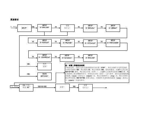
1. 2 启动CME2软件1.双击电脑桌面上的CME2快捷方式图标,启动CME2软件,出现如图所示窗口:提示:当CME2软件运行时,键盘上的F12键可用做驱动器去使能用途。
2.点击上图中的“OK”后,如通讯端口已经被设置,可出现类似下图窗口:如果“基本设置”选项还未被配置,“基本配置”窗口便会自动弹出。
1. 3 串口设置1.如果串口或者CAN口还没有被选择,“通讯向导”窗口便会自动弹出,如下图所示:2.如果CME2的主界面已经打开,可以选择“Tools”菜单下的“Communication Wizard”。
3.选择“Serial Ports”然后点击“Next”,打开“Communication Wizard Select Ports/Serial Ports”窗口,如下图所示:4.从可用的串口中选择用于与驱动器通讯的COM口。
在可用的串口中选中后,点击“Add”,将要用的COM口添加即可;也可在所选的COM口中,点击“Remove”将其移除。
5.点击“Next”保存选项,并打开通讯向导的串口设置窗口,如下图所示:6.配置相应的COM口,设置其波特率。
7.点击“Finish”保存选项。
1. 4 CAN网络参数配置1.如果串口或者CAN口还没有被选择,“通讯向导”窗口便会自动弹出,如下图所示:2.如果CME2的主界面已经打开,可以选择“Tools”菜单下的“Communication Wizard”。
3.选择CAN Network4.点击“Next”,CAN 通讯窗口打开,如下图所示:5.选择合适的CAN 卡,通道和波特率,然后点击“Finish”。
注意:1)CAN Card 列出了已经和电脑相连并且已安装好相应驱动的生产商名称;2)所有的驱动器必须设置为同样的波特率(默认为:1Mbit/s)。
1. 5 CME2连接到驱动器驱动器与CME2的连接方式如下:当只有一个驱动器连接时,软件启动后会自动连接。
1. 6 CME2软件向导2.基本配置点击打开“基本配置“窗口,如下图所示:浏览当前的基本配置情况选择:a. 假如需要,点击“Change Settings”来改变当前的设置;b. 假如你有一个准备好的“.ccx”文件,可直接点击“Load ccx File”将文件直接下载到驱动器中;c. 假如要配置Servo Tube 电机,直接点击“ServoTube Setup”;d. 假如要接受当前显示的设置,直接选择“Cancel”。
2.1 改变基本设置1.点击“Change Settings”来改变驱动器的设置,不同的设置选项因不同的驱动器而改变。
2.设置电机选项3.设置反馈选项4.设置工作模式5.设置混合选项6.当配置好各选项后,点击“Finish”完成基本设置。
2.2 ServoTube电机配置ServoTube 电机配置主要针对于使用Copley ServoTube 直线电机。
1.在“基本设置”界面上,点击“ServoTube Setup”开始基本设置向导。
2.选择合适的电机系列和型号,“Invert Motor Direction”可选,可选的“Additional Encoder Option ”只适用于某些系列的电机,选择合适的分辨率的编码器(1micro meter 或者5micro meter)。
如下图所示:3.设置操作模式4.设置混合选项5.当对当前的设置满意后,点击“Finish”完成设置。
6.如要测试电机的运行,用Jog运行电机。
3.电机/反馈参数配置3.1 电机/反馈参数窗口概览如果系统安装了两个反馈原件,需要确认电机的转数和位置的距离是够对应,他们之间的关系用Ratio来表示。
3.6 反馈注意事项1.Encoder 和Resolver一些Copley驱动器提供了Encoder 和Resolver两种反馈方式的版本。
Encoder版本支持数字差分信号或者模拟sin/cos信号的编码器,并且此版本的驱动器通常需要Hall来整定无刷电机的相位。
Resolver版本支持独立的,单端的,发射型的Resolver。
2.双反馈型驱动器一些Copley驱动器可以通过主编码器通道,次编码器通道(multi-mode port),或者两个通道接收电机,负载,或者两者的位置反馈信号。
(一些驱动器可以工作在没有编码器和Resolver的模式)当驱动器被配置成带有multi-mode port时,multi-mode port可以:●提供基于数字编码器输入的编码器数字缓冲输出信号●提供基于模拟编码器或者Resolver的转换后的数字编码器输出信号●提供次编码器通道做为双编码器位置模式。
此模式下,位于负载端的编码器做为位置闭环,电机端编码器或者Resolver做为速度环反馈。
双闭环设置如下。
驱动器从主编码器通道端接收电机端增量式编码器信号,位置(负载)端编码器信号来自于Multi-mode Port(次编码器通道)。
电机转数与负载端编码器转数比例是1:10。
3.8 Brake/Stop 注意事项许多控制系统在驱动器去使能后需要刹车使电机保持。
在带刹车系统中,用硬件或软件指令去使能后以下序列事件将会发生:●电机开始减速(以位置模式的Abort Deceleration或者速度模式的Fast Stop Ramp减速)同时Brake/Stop Delay time计数开始,这使得电机在执行刹车之前先减慢速度。
●当电机减速到Brake Activation Velocity或者Brake/Stop Delay time溢出时,刹车输出有效并且PWM Delay Brake/Stop Response Time计数开始。
●当PWM Delay Brake/Stop Response Time到达时,驱动器PWM输出断开,这个延时保证了在驱动器PWM输出断开前刹车有足够的时间有效。
这个序列在电流模式下无效。
在电流模式下,当去使能信号有效后,驱动器输出断开,刹车也立即有效。
3.9 计算功能1. 点击“Calculate”计算并且显示设置。
2. 确认峰值电流限制,持续电流限制,和速度环速度限制。
假如这些参数中的一个或多个看上去不合理,点击“Cancel”并且检查:峰值力矩(力),持续力矩(力),速度限制,和力矩(力)常数。
假如必要的话修改它们。
(请看旋转电机设置参数或者直线电机设置参数)假如Motor/Feedback 值正确但是峰值电流限制,持续电流限制,或者速度环速度限制值对于当前的应用并不是最优化的,在调试的过程中改变它们。
3. 点击OK将这些值下载到驱动器的RAM中。
注意:当从一个文件中下载电机数据,假如文件中电机接线配置跟当前存在驱动器中的配置不匹配,CME提示确认正确的配置。
点击Yes选择配置文件,这些配置将被做为电机的相位部分进行测试。
4. 在主界面上,点击“Save to Flash”保存配置以防配置丢失。
4.数字输入/输出配置●点击“Input/Output”打开Input/Output窗口。
●需要的话,设置“Digital Inputs”。
●需要的话,设置“Digital Outputs”。
●点击“Close”,保存设置到驱动器的RAM中●在主界面上,点击“Save to Flash”保存配置以防配置丢失。
4.1 数字输入1. 数字输入界面概览3. 标准的输入功能分配Enable Input: 在大多数Copley驱动器中,IN1被专门配置为硬件使能输入。
Accelus系列默认IN2为硬件使能输入。
其它的输入口可被定义为额外的使能输入。
假如有多个输入被配置为硬件使能输入,当这些使能输入都有效时,PWM才有输出。
Motor Over Temperature: 在大多数Copley驱动器中,IN5位于电机反馈接头中,并被做为电机温度传感器接口。
Other:其它输入口的功能可根据驱动器的控制模式来确定。
4.2 数字输出1. 数字输出界面概览2. 标准输出功能标准输出功能描述如下:3. 数字输出配置:Custom Event驱动器的任意一个数字输出可以被定义响应一组事件,包括错误,报警和状态指示。