中文版思科实用实验项目大全
- 格式:pdf
- 大小:1.11 MB
- 文档页数:94
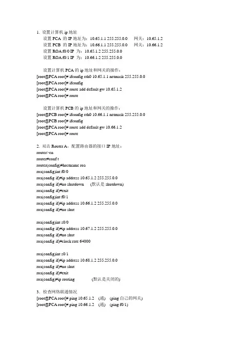
1. 设置计算机ip地址设置PCA的IP地址为:10.65.1.1 255.255.0.0 网关:10.65.1.2 设置PCB 的IP地址为:10.66.1.1 255.255.0.0 网关:10.66.1.2 设置ROA f0/0 IP为:10.65.1.2 255.255.0.0设置ROA f0/1 IP为:10.66.1.2 255.255.0.0设置计算机PCA的ip地址和网关的操作:[root@PCA root]# ifconfig eth0 10.65.1.1 netmask 255.255.0.0[root@PCA root]# ifconfig[root@PCA root]# route add default gw 10.65.1.2[root@PCA root]# route设置计算机PCB的ip地址和网关的操作:[root@PCB root]# ifconfig eth0 10.66.1.1 netmask 255.255.0.0[root@PCB root]# ifconfig[root@PCA root]# route add default gw 10.66.1.2[root@PCA root]# route2. 双击Router A,配置路由器的接口IP地址:router>enrouter#conf trouter(config)#hostname roaroa(config)int f0/0roa(config-if)#ip address 10.65.1.2 255.255.0.0roa(config-if)#no shutdown (默认是shutdown)roa(config-if)#exitroa(config)int f0/1roa(config-if)#ip address 10.66.1.2 255.255.0.0roa(config-if)#no shutroa(config)int s0/0roa(config-if)#ip address 10.67.1.2 255.255.0.0roa(config-if)#no shutroa(config-if)#clock rate 64000roa(config)int s0/1roa(config-if)#ip address 10.68.1.2 255.255.0.0roa(config-if)#no shutroa(config-if)#exitroa(config)#ip routing (默认是关闭的)3.检查网络联通情况[root@PCA root]# ping 10.65.1.2 (通) (ping自己的网关)[root@PCA root]# ping 10.66.1.2 (通) (ping f0/1)[root@PCA root]# ping 10.66.1.1 (通) (ping PCB)[root@PCA root]# ping 10.67.1.2 (不通) (端口空时down) [root@PCA root]# ping 10.68.1.2 (不通) (端口空时down)[root@PCB root]# ping 10.66.1.2 (通) (ping自己的网关) [root@PCB root]# ping 10.65.1.2 (通) (ping f0/0)[root@PCB root]# ping 10.65.1.1 (通) (ping PCA)[root@PCB root]# ping 10.67.1.2 (不通) (端口s0/0空时down) [root@PCB root]# ping 10.68.1.2 (不通) (端口s0/1空时down)roa#ping 10.65.1.1 (通) (ping PCA)roa#ping 10.65.1.2 (通) (ping f0/0)roa#ping 10.66.1.1 (通) (ping PCB)roa#ping 10.66.1.2 (通) (ping f0/1)roa#ping 10.67.1.2 (不通) (端口s0/0空时down)roa#ping 10.68.1.2 (不通) (端口s0/1空时down)下面我们做这个几个小实验:(1) 将路由器的接口f0/0关闭roa#conf troa(config)#int f0/0roa(config-if)#shutdownroa(config-if)#endroa#ping 10.65.1.2 (不通,端口down掉)roa#show int f0/0 (f0/0 is down,line proto is down) [root@PCA root]# ping 10.65.1.2 (不通)激活f0/0端口:roa(config)#int f0/0roa(config-if)#no shutroa(config-if)#endroa#ping 10.65.1.2 (通)去掉PCA与f0/0的连线roa#sh int f0/0 (f0/0 is up,line proto is down)roa#ping 10.65.1.2 (不通)roa#sh int s0/0 (s0/0 is down,line proto is down)roa#sh int s0/1 (s0/1 is down,line proto is down)serial口当没有连线时???(2) 关闭路由器的路由roa#conf troa(config)#no ip routing[root@PCA root]# ping 10.65.1.2 (通) (ping 自己的网关)[root@PCA root]# ping 10.66.1.1 (不通)(路由器不能转发了)[root@PCB root]# ping 10.66.1.2 (通) (ping 自己的网关)[root@PCB root]# ping 10.65.1.1 (不通)(路由器不能转发了)计算机可以ping与其相连的端口,但不能ping通下面的计算机,因为no ip routing后不具备转发的功能了。
思科路由部分11个实验项目:全程记录+讲解+知识点思科路由部分11个实验项目:全程记录+讲解+知识点实验基于Dynamips-0.2.6-Rc4 | unzip-c3620-i-mz.122-37.bin |unzip-c3640-js-mz.124-10 with NM-16ESW实验平台双Xeon 3.0 4G ECC 运行稳定后CPU 40%左右实验1:在P1范围内实现RIPv2实验2:在P1范围内实现基于RIPv2的等价负载均衡实验3:在P1范围内实现基于RIPv2的Key-Chain密钥实验实验4:在P2范围内实现IGRP的非等价负载均衡实验5:全区域中通过桢中继实现RIPv2路由协议 + 密钥验证实验6:全区域中实现EIGRP路由+FR+非等价负载均衡+验证实验7:OSPF基本配置[P1区域内配置]+DR/BDR考察实验8:单区域NBMA环境OSPF实现+验证实验9:多区域OSPF实现实验10:简单的路由重发布末节区域完全末节区域 NSSA区域 Virtual-Link实验11:被动接口路由更新过滤策略路由路由单项重发布以及AD/Metric更改路由双向重发布P1配置部分P1R1-P1R2192.168.1.1 - 192.168.1.2 /24 P1R1上配置Lo0 200.200.200.200 /24 P1R1-P1R3192.168.2.1 - 192.168.2.2 /24P1R3-P1R4192.168.3.1 - 192.168.3.2 /24P1R2-P1R4192.168.4.1 - 192.168.4.2 /24P1R1-BBR1 - 10.0.0.2 /8P1R2-BBR1 - 10.0.0.3 /8P2配置部分P2R1-P2R2172.16.1.1 - 172.16.1.2 /16 P2R1上配置Lo0 100.100.100.100 /8 P2R1-P2R3172.17.1.1 - 172.17.1.2 /16P2R3-P2R4172.18.1.1 - 172.18.1.2 /16P2R2-P2R4172.19.1.1 - 172.19.1.2 /16P2R1-BBR2 - 11.0.0.2 /8P2R2-BBR2 - 11.0.0.3 /8BBR配置部分BBR1-BBR2219.146.241.1 -219.146.241.2 /24BBR1 s0/0.1 -s0/0.210.0.0.1BBR2 s0/0.1 -s0/0.211.0.0.1BBR2-SW1219.146.242.1 - 219.146.242.2BBR1-SW2219.146.243.1 - 219.146.243.2SW1-SW2219.146.244.1 - 219.146.244.2SR配置部分SR1-SW1 101.0.0.1 - 101.0.0.2SR2-SW1 102.0.0.1 - 102.0.0.2SR3-SW2 103.0.0.1 - 103.0.0.2SR4-SW2 104.0.0.1 - 104.0.0.2SR1:lo0 105.0.0.1 Lo1 106.0.0.1SR2:lo0 107.0.0.1 Lo1 108.0.0.1实验1:在P1范围内实现RIPv2[P1R1]router ripver 2net 192.168.1.0net 192.168.2.0net 200.200.200.0[P1R2]router ripver 2net 192.168.1.0net 192.168.4.0[P1R3]router ripver 2net 192.168.2.0net 192.168.3.0[P1R4]router ripver 2net 192.168.3.0net 192.168.4.0验证结果,P1R1[Copy to clipboard]CODE:sh ip route:C 200.200.200.0/24 is directly connected, Loopback0R 192.168.4.0/24 [120/2] via 192.168.2.2, 00:00:22, FastEthernet0/0C 192.168.1.0/24 is directly connected, Serial1/1C 192.168.2.0/24 is directly connected, FastEthernet0/0R 192.168.3.0/24 [120/1] via 192.168.2.2, 00:00:22, FastEthernet0/0 注意:区分RIP两个版本,配置时候必须配置相同的rip version,虽然有办法让他们协同工作,但是基本上没什么意义RIPV1分类路由,没30秒发送一次更新分组,分组中不包含子网掩码信息,不支持 VLSM,默认进行边界自动路由汇总,且不可关闭,所以该路由不能支持非连续网络.不支持身份验证. 使用跳数作为度量,管理距离 120.每个分组中最多只能包含25个路由信息.使用广播进行路由更新.RIPV2无类路由,发送分组中含有子网掩码信息,支持VLSM,但默认该协议开启了自动汇总功能,所以如需向不同主类网络发送子网信息,需要手工关闭自动汇总功能(no auto-summary),RIPV2只支持将路由汇总至主类网络,无法将不同主类网络汇总,所以不支持CIDR.使用多播224.0.0.9进行路由更新,只有对应的多播MAC地址能够响应分组,在MAC层就能区分是否对分组响应.支持身份验证.分类路由选择协议,当发送路由分组的接口所处子网与分组相关的子网属于同一主类网络,那么路由器在该接口可以把具体的子网发送出去.路由器假设该接口与分组子网使用相同的子网掩码.什么是连续子网:属于同一主类网络,使用相同的子网掩码就是连续的子网.否则就是非连续子网.在接口上手工汇总命令:ip summary-address rip 被汇总子网被汇总子网掩码RIP 使用UDP(用户报文协议)520端口传输路由更新分组RIP只能做等价负载均衡实验2 在P1范围内实现基于RIPv2的等价负载均衡P1R1上的Lo0为200.200.200.200,作为此实验的目的IP[P1R4]int f0/0no ip route-cacheint s1/0no ip route-cacheaccess-list 101 permit ip icmp any 200.200.200.0 0.0.0.255debug ip pac 101验证结果[P1R2]router ripver 2net 192.168.1.0net 192.168.4.0[P1R3]router ripver 2net 192.168.2.0net 192.168.3.0[P1R4]router ripver 2net 192.168.3.0net 192.168.4.0P1R4上sh ip route,可以看到[Copy to clipboard]CODE:Gateway of last resort is not setR 200.200.200.0/24 [120/2] via 192.168.4.1, 00:00:16, FastEthernet0/0 [120/2] via 192.168.3.1, 00:00:09, Serial1/0C 192.168.4.0/24 is directly connected, FastEthernet0/0R 192.168.1.0/24 [120/1] via 192.168.4.1, 00:00:16, FastEthernet0/0 R 192.168.2.0/24 [120/1] via 192.168.3.1, 00:00:09, Serial1/0C 192.168.3.0/24 is directly connected, Serial1/0到达200.200.200.0网段的metric完全相同,并且通过两个出口P1R4#ping 200.200.200.200 re 2[Copy to clipboard]CODE:Type escape sequence to abort.Sending 2, 100-byte ICMP Echos to 200.200.200.200, timeout is 2 seconds:!!Success rate is 100 percent (2/2), round-trip min/avg/max = 12/14/16 msP1R4#16:00:24: IP: tableid=0, s=192.168.4.2 (local), d=200.200.200.200 (FastEthernet0/0), routed via RIB16:00:24: IP: s=192.168.4.2 (local), d=200.200.200.200 (FastEthernet0/0), len 100, sending16:00:24: IP: tableid=0, s=192.168.3.2 (local), d=200.200.200.200 (Serial1/0), routed via RIB16:00:24: IP: s=192.168.3.2 (local), d=200.200.200.200 (Serial1/0), len 100, sending注意1.route-cache是进程交换, ip route-cache是快速交换, ip route-cache optimum是最优交换, route-cache distributed是分布式最优,负载均衡需要切换为进程交换(根据分组处理,而不是目的地),7000以上系列需要no ip cef2.通过定义ACL定义过滤,然后debug抓取特定的数据包,可以最优化显示debug结果均衡负载的知识:均衡负载可以是基于目标地址或者是基于每个packet的所谓基于目标地址的均衡负载,是说假如有2条到达目标地址的路径,那么第一个packet将通过第一条链路到达第一个目标设备,第二个packet将通过第二条链路到达第二个目标设备,第三个packet又将通过第一条链路到达第三个目标设备等等,以次类推.当Cisco路由器工作在默认的交换模式,Fast Switching(快速交换)模式下,就使用这种类型的均衡负载 Fast Switching的工作原理是:当路由器对第一个packet进行发往目标地址的处理的时候,先查看路由表和选择出口接口,然后获取组成 frame的信息(比如ARP表的查询)并进行封装,然后传输.之前获取的这些路由和数据链路信息将被保存在快速交换的cache中.接下来,当有要到达和第一个包相同的目标地址的包的时候,就可以不进行路由表和ARP表的查询,直接对packet进行交换快速交换降低了CPU的占用和处理时间,并意味着去往某个目标地址的packet都从相同的路由器接口被路由出去.当有到达同一网络不同主机的packet,路由器可能会吧这些packet通过另外一条链路进行路由.因此,路由器能做的最好的就是给予目标地址的均衡负载所谓基于基于packet的均衡负载,是说假如有2条到达目标地址的路径,那么第一个packet将通过第一条链路到达目标设备,第二个packet将通过第二条链路到达目标设备,第三个packet又将通过第一条链路到达目标设备等等,以次类推.(这里考虑的是等价的均衡负载) Cisco路由器工作在Process Switching(进程交换)模式的时候就采用基于packet的均衡负载进程交换,是指每次对packet的交换,都要查询路由表,选择出口接口和查询数据链路信息,因为每次的路由决策都是独立的.要在某个接口打开进程交换模式,使用no ip route-cache命令.实验3 在P1范围内实现基于RIPv2的Key-Chain密钥实验 [P1R1]key chain ciscokey 1key-string mypasswordint f0/0ip rip auth key-chain ciscoip rip auth mode md 5int s1/1ip rip auth key-chain ciscoip rip auth mode md5验证结果在P1R1上定义密钥以后,分别在s1/1和f0/0上面启用,在其他路由器并没有启用相同的密钥的时候,通过debug ip rip eve查看:16:18:45: RIP: ignored v2 packet from 192.168.1.2 (invalid authentication)sh ip route查看R 192.168.3.0/24 is possibly down, routing via 192.168.2.2, FastEthernet0/0 说明因为密钥匹配原因,packet ignored,并且路由条目状态变化为possibly down在P1R2上定义同样密钥后debug 信息显示Page 5 of Cisco Tec! - Powered by Discuz! Board 31P1R4上sh ip route,可以看到16:31:16: RIP: received packet with MD5 authentication认证成功附加部分在P1R2上采用同样密钥,但是在接口上应用的时候如果采用明文方式 ip rip auth mod text(P1R1采用MD5加密)因为两边不匹配,则一样会invalid authentication注意可以在路由器上配置RIPv2消息认证包括:明文或MD5加密密码在钥匙链(key-chain)上定义多个秘钥(key)或密码,后者可选定义秘钥链名称:key chain test定义秘钥 key 1定义密码key-string cisco在接口上启用 int e0/0 ip rip authentication key-chain test定义发送方式 ip rip authtication mode md5记住,钥匙链-钥匙-钥匙的凹凸代表密码,必须在个锁(接口)上使用此钥匙(引用)sh ip pro可以查看version和keychain情况Default version control: send version 2, receive version 2 Interface Send Recv Triggered RIP Key-chain FastEthernet0/0 2 2 ciscoSerial1/1 2 2 ciscoLoopback0 2 2实验4 在P2范围内实现IGRP的非等价负载均衡等价负载均衡同RIP部分,设置上没什么特殊之处[P2R4]int f0/0bandwidth 10000no ip route-cacheint s1/0bandwidth 1000no ip route-cacherouter igrp 100vari 10access-list 101 permit ip icmp any 100.100.100.0 0.0.0.255debug ip pac 101验证结果使用sh int f0/0察看其默认BW为BW 100000 Kbit使用sh int s1/0察看其默认BW为BW 1544 Kbit但是奇怪的是,我还没有设置variance,且BW不同的情况下,基于Dynamips的metric计算值竟然相同,先不管它I 100.0.0.0/8 [100/8986] via 172.19.1.1, 00:00:09, FastEthernet0/0[100/8986] via 172.18.1.1, 00:00:18, Serial1/0如果只是设置了带宽,则所有的pac将从f0/0发出[Copy to clipboard]CODE:P2R4#ping 100.100.100.100 re 2Type escape sequence to abort.Sending 2, 100-byte ICMP Echos to 100.100.100.100, timeout is 2 seconds:!!Success rate is 100 percent (2/2), round-trip min/avg/max = 12/14/16 msP2R4#00:54:07: IP: tableid=0, s=172.19.1.2 (local), d=100.100.100.100 (FastEthernet0/0), routed via RIB00:54:07: IP: s=172.19.1.2 (local), d=100.100.100.100 (FastEthernet0/0), len 100, sending00:54:07: IP: tableid=0, s=172.19.1.2 (local), d=100.100.100.100 (FastEthernet0/0), routed via RIB00:54:07: IP: s=172.19.1.2 (local), d=100.100.100.100 (FastEthernet0/0), len 100,sending16:31:16: RIP: received packet with MD5 authentication认证成功附加部分在P1R2上采用同样密钥,但是在接口上应用的时候如果采用明文方式 ip rip auth mod text(P1R1采用MD5加密)因为两边不匹配,则一样会invalid authentication设置好variance以后,sh ip routeI 100.0.0.0/8 [100/8986] via 172.19.1.1, 00:01:09, FastEthernet0/0[100/12510] via 172.18.1.1, 00:00:16, Serial1/0两条路出来了,然后观察抓包即可[Copy to clipboard]CODE:P1R4#ping 100.100.100.100 re 2Type escape sequence to abort.Sending 2, 100-byte ICMP Echos to 100.100.100.100, timeout is 2 seconds:!!Success rate is 100 percent (2/2), round-trip min/avg/max = 12/14/16 msP1R4#00:58:24: IP: tableid=0, s=172.19.1.1 (local), d=100.100.100.100 (FastEthernet0/0), routed via RIB00:58:24: IP: s=172.19.1.1 (local), d=100.100.100.100 (FastEthernet0/0), len 100, sending00:58:24: IP: tableid=0, s=172.18.1.1 (local), d=100.100.100.100 (Serial1/0), routed via RIB00:58:24: IP: s=172.18.1.1 (local), d=100.100.100.100 (Serial1/0), len 100, sending注意:设置BW中的两个错误1.将两个BW值一个500000 一个1500,设置variance 为 334,5000000/1500=333,但是经过实验,variance设置范围为1-1282.设置BW值不适当的时候,可能会导致sh ip route显示possiblydown,这个时候重新启用IGRP即可知识点:IP协议出现最早,最大跳数只支持15跳,只适合小型网络;IGRP是Cisco公司为了弥补RIP的缺陷而开发设计,适合更大的网络,最大支持255跳,为了减轻网络的负担,将默认的更新周期从RIP的30秒改为90秒,但是这也造成了网络拓扑变化时收敛速度变迟缓了。
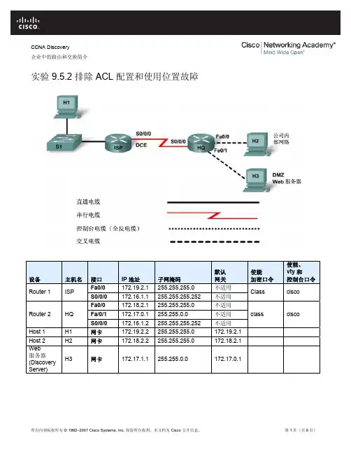
CCNA Discovery企业中的路由和交换简介实验 9.5.2 排除 ACL配置和使用位置故障设备主机名 接口 IP 地址 子网掩码 默认 网关 使能 加密口令 使能、 vty 和 控制台口令Fa0/0172.19.2.1 255.255.255.0 不适用 Router 1 ISP S0/0/0172.16.1.1 255.255.255.252 不适用 Class cisco Fa0/0172.18.2.1 255.255.255.0 不适用 Fa/0/1 172.17.0.1 255.255.0.0 不适用 Router 2HQ S0/0/0 172.16.1.2 255.255.255.252 不适用 class cisco Host 1H1 网卡 172.19.2.2 255.255.255.0 172.19.2.1 Host 2H2 网卡 172.18.2.2 255.255.255.0 172.18.2.1 Web服务器(DiscoveryServer)H3 网卡 172.17.1.1 255.255.0.0 172.17.0.1目标•在路由器中加载预配置。
•找到通信失败的位置。
•收集误配置的 ACL 的相关信息。
•分析信息,确定通信故障的原因。
•提出用于纠正网络错误的解决方案。
•实施用于纠正网络错误的解决方案。
背景/准备工作一家小型的制造企业想通过 Internet 宣传产品。
他们需要立即在网上提供产品简介、报告和证书,向潜在客户促销产品。
由于他们需要一个安全的基础架构来支持其内部和外部网络要求,因此您设计了一个包含内部企业网络区域和非军事区 (DMZ) 的两级体系结构。
企业网络区域中放置专用服务器和内部客户端。
DMZ 中只放置一台外部服务器,用于提供万维网服务。
由于公司只能管理自己的 HQ 路由器,而不能管理 ISP 的路由器,因此所有 ACL 都必须应用到 HQ 路由器。


目录实验一路由器基本配置............................................ 错误!未指定书签。
实验二静态路由......................................................... 错误!未指定书签。
实验三缺省路由......................................................... 错误!未指定书签。
实验四静态路由&缺省路由&CDP协议............... 错误!未指定书签。
实验五三层交换机实现VLAN间通信................. 错误!未指定书签。
实验六Vtp ................................................................... 错误!未指定书签。
实验七生成树STP ..................................................... 错误!未指定书签。
实验八RIP路由协议1 ............................................. 错误!未指定书签。
实验九RIP路由协议2 ............................................. 错误!未指定书签。
实验十OSPF单区域1 .............................................. 错误!未指定书签。
实验十一OSPF单区域2 ......................................... 错误!未指定书签。
实验十二OSPF单区域3 ......................................... 错误!未指定书签。
实验十三EIGRP ........................................................ 错误!未指定书签。

目录使用帮助 (1)1.计算机命令: (1)2.交换机支持的命令: (1)3.路由器支持的命令: (2)4.PIX防火墙命令 (6)理论学习 (7)网络的发展与应用 (7)网络互联基础 (8)交换机原理与应用 (13)路由器原理与应用 (17)常见广域网协议及特点 (23)PIX防火墙特点与应用 (24)五、PIX防火墙举例 (29)PIX防火墙应用举例 (29)常见操作操作错误: (31)实验一口令和主机名设置 (31)实验二计算机与交换机IP地址设置 (36)实验三交换机VLAN实验 (38)实验四路由器的升级 (41)实验五路由器接口ip及直联路由 (44)实验六一个vlan下的单臂路由 (46)实验七子接口单臂路由 (48)实验八静态路由 (50)实验九动态路由 (53)实验十交换机和路由器组合实验 (56)实验十一访问控制列表 (59)实验十二综合实验 (62)实验十三《三层交换机实验》 (64)实验十四《三层交换与二层交换机结合》 (66)实验十五《三层交换机与路由器的连接》 (67)实验十六《交换机的通道技术》 (68)实验十七《交换机与路由器间的端口聚合》 (70)实验十八《静态NAT配置》 (71)实验十九《常见NAT配置》 (72)实验二十防火墙设置 (75)实验二十一点到点联接时OSPF的配置 (77)实验二十二广播方式的OSPF配置 (79)实验二十三非广播方式的OSPF配置 (80)实验二十四PPP配置实验 (82)实验二十五实验室条件下点对点帧中继配置 (83)实验二十六点对点的帧中继配置 (84)实验二十七子接口帧中继配置 (85)实验二十八配置BGP (87)实验二十九GRE VPN的配置 (88)实验三十ipsec site-to-site VPN配置 (90)使用帮助1.计算机命令:PCAlogin:root;使用root用户password:linux;口令是linux#shutdown-hnow;同init0关机#logout;退出登录#login;登录#ifconfig;显示IP地址#ifconfigeth0<ipaddress>netmask<netmask>;设置IP地址#ifconfigeth0<ipaddress>netmask<netmask>down;删除IP地址#routeadd0.0.0.0gw<ip>;设置网关#routedel0.0.0.0gw<ip>;删除网关#routeadddefaultgw<ip>;设置网关#routedeldefaultgw<ip>;删除网关#route;显示网关#ping<ip>;测试网络#telnet<ip>;远程登录2.交换机支持的命令:交换机基本状态:switch:;交换机的ROM状态rommon>;路由器的ROM状态hostname>;用户模式hostname#;特权模式hostname(config)#;全局配置模式hostname(config-if)#;接口状态交换机口令设置:switch>enable;进入特权模式switch#configterminal;进入全局配置模式switch(config)#hostname<hostname>;设置交换机的主机名switch(config)#enablesecretxxx;设置特权加密口令switch(config)#enablepasswordxxa;设置特权非密口令switch(config)#lineconsole0;进入控制台口switch(config-line)#linevty04;进入虚拟终端switch(config-line)#login;允许登录switch(config-line)#passwordxx;设置登录口令xxswitch#exit;返回命令交换机VLAN设置:switch#vlandatabase;进入VLAN设置switch(vlan)#vlan2;建VLAN2switch(vlan)#novlan2;删vlan2switch(vlan)#vtpdomain<name>;设置发vtp域名switch(vlan)#vtppassword<word>;设置发vtp密码switch(vlan)#vtpserver;设置发vtp模式switch(vlan)#vtpclient;设置发vtp模式switch(vlan)#vtppruning;设置vtp允许switch(config)#intf0/1;进入端口1switch(config-if)#switchportaccessvlan2;当前端口加入vlan2switch(config-if)#switchportmodetrunk;设置为干线switch(config-if)#switchporttrunkallowedvlan1,2;设置允许的vlanswitch(config-if)#switchporttrunkencapdot1q;设置vlan中继switch(config-if)#speed;设置接口速度switch(config-if)#duplex;设置接口作方式交换机设置IP地址:switch(config)#interfacevlan1;进入vlan1switch(config-if)#ipaddress<IP><mask>;设置IP地址switch(config)#ipdefault-gateway<IP>;设置默认网关switch#dirflash:;查看闪存交换机显示命令:switch#write;保存配置信息switch#showvtp;查看vtp配置信息switch#showrun;查看当前配置信息switch#showvlan;查看vlan配置信息switch#showinterface;查看端口信息switch#showintf0/0;查看指定端口信息3.路由器支持的命令:路由器显示命令:router#showrun;显示配置信息router#showinterface;显示接口信息router#showiproute;显示路由信息router#showcdpnei;显示邻居信息router#reload;重新起动路由器口令设置:router>enable;进入特权模式router#configterminal;进入全局配置模式router(config)#hostname<hostname>;设置交换机的主机名router(config)#enablesecretxxx;设置特权加密口令router(config)#enablepasswordxxb;设置特权非密口令router(config)#lineconsole0;进入控制台口router(config-line)#linevty04;进入虚拟终端router(config-line)#login;要求口令验证router(config-line)#passwordxx;设置登录口令xxrouter(config)#(Ctrl+z);返回特权模式router#exit;返回命令路由器配置:router(config)#ints0/0;进入Serail接口router(config-if)#noshutdown;激活当前接口router(config-if)#clockrate64000;设置同步时钟router(config-if)#ipaddress<ip><netmask>;设置IP地址router(config-if)#ipaddress<ip><netmask>second;设置第二个IProuter(config-if)#intf0/0.1;进入子接口router(config-subif.1)#ipaddress<ip><netmask>;设置子接口IProuter(config-subif.1)#encapsulationdot1q<n>;绑定vlan中继协议router(config)#config-register0x2142;跳过配置文件router(config)#config-register0x2102;正常使用配置文件router#reload;重新引导路由器文件操作:router#copyrunning-configstartup-config;保存配置router#copyrunning-configtftp;保存配置到tftprouter#copystartup-configtftp;开机配置存到tftprouter#copytftpflash:;下传文件到flashrouter#copytftpstartup-config;下载配置文件ROM状态:Ctrl+Break;进入ROM监控状态rommon>confreg0x2142;跳过配置文件rommon>confreg0x2102;恢复配置文件rommon>reset;重新引导rommon>copyxmodem:<sname>flash:<dname>;从console传输文件rommon>IP_ADDRESS=10.65.1.2;设置路由器IPrommon>IP_SUBNET_MASK=255.255.0.0;设置路由器掩码rommon>TFTP_SERVER=10.65.1.1;指定TFTP服务器IPrommon>TFTP_FILE=c2600.bin;指定下载的文件rommon>tftpdnld;从tftp下载rommon>dirflash:;查看闪存内容rommon>boot;引导IOS静态路由:iproute<ip-address><subnet-mask><gateway>;命令格式router(config)#iproute2.0.0.0255.0.0.01.1.1.2;静态路由举例router(config)#iproute0.0.0.00.0.0.01.1.1.2;默认路由举例动态路由:router(config)#iprouting;启动路由转发router(config)#routerrip;启动RIP路由协议。
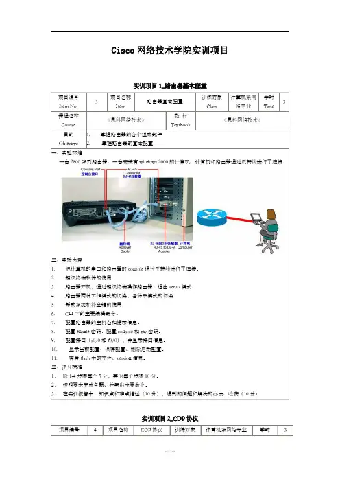
Cisco网络技术学院实训项目实训项目1_路由器基本配置项目编号Item No.3项目名称Item路由器基本配置训练对象Class计算机系网络专业学时Time3课程名称Course 《思科网络技术》教材Textbook《思科网络技术》目的Objective 1. 掌握路由器的各个组成部件2. 掌握路由器的基本配置一、实验环境一台2800系列路由器、一台安装有windows 2000的计算机、计算机和路由器通过反转线进行了连接。
二、实验内容1. 把计算机的串口和路由器的console通过反转线进行了连接。
2. 超级终端软件的使用。
3. 路由器开机,通过超级终端操作路由器;退出setup模式。
4. 路由器两种工作模式的切换,各种子模式的切换。
5. 帮助系统和补全键的使用。
6. CLI下的主要编辑命令。
7. 配置路由器的主机名和提示信息。
8. 配置enable密码、配置console和vty密码。
9. 配置接口(s0/0和f0/0),并显示接口信息。
10. 显示当前配置、保存配置、删除启动配置。
11. 查看flash中的文件、version信息。
三、评分标准1.除1-4步骤每个5分,其他每个步骤10分。
2.按照要求完成各题、并写出主要命令。
3.在实训报告中,知识点和难点描述(10分),遇到的问题和解决的办法、收获(10分)实训项目2_CDP协议项目编号4项目名称CDP协议训练对象计算机系网络专业学时3Item No.Item Class Time课程名称Course 《思科网络技术》教材Textbook《思科网络技术》目的Objective 1. 掌握cdp的工作原理2. 掌握cdp的应用一、实验环境两个同学一组,每人各操作一台路由器:两台2800系列路由器、一台交换机。
如下连接:二、实验内容1. R1和R2的s0/0接口的启用:R2的f0/0接口启用。
注意s0/0上的时钟,不配置IP地址。
2. 查看cdp邻居,清除cdp 表3. 调整cdp 发送时间间隔和保持时间间隔4. 关闭和打开接口下的cdp5. 关闭和打开整个路由的cdp6. 在R1和R2上的s0/0上配置IP地址,以及enable密码和vty密码7. R1和R2互相进行telnet三、评分标准1.每个步骤10分。
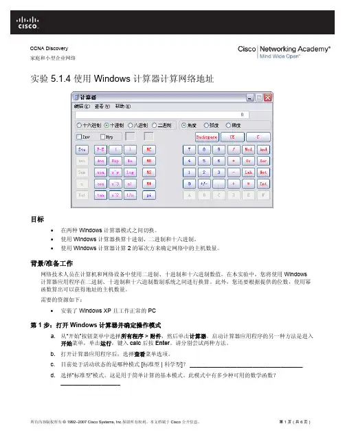
CCNA Discovery家庭和小型企业网络实验 5.1.4 使用 Windows 计算器计算网络地址目标•在两种 Windows 计算器模式之间切换。
•使用 Windows 计算器换算十进制、二进制和十六进制。
•使用 Windows 计算器计算 2 的幂次方来确定网络中的主机数量。
背景/准备工作网络技术人员在计算机和网络设备中使用二进制、十进制和十六进制数值。
在本实验中,您将使用 Windows 计算器应用程序在二进制、十进制和十六进制数制系统之间进行换算。
此外,您还要根据提供的位数,使用幂函数算出可以获得地址的主机数量。
需要的资源如下:•安装了 Windows XP 且工作正常的 PC第 1 步:打开 Windows 计算器并确定操作模式a. 从“开始”按钮菜单中选择所有程序 > 附件,然后单击计算器。
启动计算器应用程序的另一种方法是进入开始菜单,单击运行,键入calc后按Enter。
请分别尝试两种方法。
b. 打开计算器应用程序后,选择查看菜单选项。
c. 目前处于活动状态的是哪种模式 [标准型 | 科学型]? ____________________________________d. 选择“标准型”模式。
这是用于简单计算的基本模式。
此模式中有多少种可用的数学函数?___________________e. 选择“查看”菜单选项中的“科学型”计算器模式。
f. 此模式中有多少种可用的数学函数? ___________________________________________________ 第 2 步:在数制系统间转换a. 进入科学型模式。
请注意可用的数制系统模式 — 十六进制、十进制、八进制和二进制。
b. 目前处于活动状态的是哪个数制系统?_____________c. 在十进制模式下,数字键区中有哪些数字处于活动状态?__________________d. 单击二进制模式单选按钮。
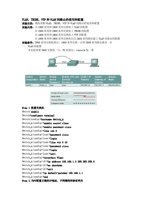
VLAN,TRUNK,VTP和VLAN间路由的使用和配置实验目的:熟练掌握VLAN,TRUNK,VTP和VLAN间路由的使用和配置实验内容:在1900系列和2900系列交换机上VLAN的配置在1900系列和2900系列交换机上TRUNK的配置在1900系列和2900系列交换机上VTP的配置在1900系列和2900系列交换机以及2600系列路由器上VLAN间路由的配置实验条件:2900系列交换机两台,1900系列交换一台和2600系列路由器各一台一.VLAN的配置本实验需要2900交换机一台,PC机两台,console线一条Step 1 配置交换机Switch>enableSwitch#configure terminalSwitch(config)#hostname Switch_ASwitch_A(config)#enable secret classSwitch_A(config)#enable password ciscoSwitch_A(config)#line con 0Switch_A(config-line)#password ciscoSwitch_A(config-line)#loginSwitch_A(config-line)#line vty 0 15Switch_A(config-line)#password ciscoSwitch_A(config-line)#loginSwitch_A(config-line)#exitSwitch_A(config)#interface Vlan1Switch_A(config-if)#ip address 192.168.1.2 255.255.255.0Switch_A(config-if)#no shutdownSwitch_A(config-if)#exitSwitch_A(config)#ip default-gateway 192.168.1.1Switch_A(config)#endStep 2 为PC配置正确的IP地址,子网掩码和缺省网关Step 3 检测连通性由switch ping两台PC机,检测连通性Step 4 显示VLAN的接口信息2900:Switch_A#show vlan1900:Switch_A#show vlan-membershipStep 5 创建,命名VLAN2900:Switch_A#vlan databaseSwitch_A(vlan)#vlan 2 name VLAN2Switch_A(vlan)#vlan 3 name VLAN3Switch_A(vlan)#exit1900:Switch_A#configure terminalSwitch_A(config)#vlan 2 name VLAN2Switch_A(config)#vlan 3 name VLAN3Step 6 安排4,5,6端口到VLAN 22900:Switch_A#configure terminalSwitch_A(config)#interface fastethernet 0/4 Switch_A(config-if)#switchport mode access Switch_A(config-if)#switchport access vlan 2 Switch_A(config-if)#interface fastethernet 0/5 Switch_A(config-if)#switchport mode access Switch_A(config-if)#switchport access vlan 2 Switch_A(config-if)#interface fastethernet 0/6 Switch_A(config-if)#switchport mode access Switch_A(config-if)#switchport access vlan 2 Switch_A(config-if)#end1900:Switch_A#configure terminalSwitch_A(config)#interface Ethernet 0/4Switch_A(config-if)#vlan static 2Switch_A(config-if)#interface Ethernet 0/5 Switch_A(config-if)#vlan static 2Switch_A(config-if)#interface Ethernet 0/6 Switch_A(config-if)#vlan static 2Switch_A(config)#endStep 7 显示VLAN的接口信息2900:Switch_A#show vlan1900:Switch_A#show vlan-membershipStep 8 安排7,8,9端口到VLAN 3Switch_A#configure terminalSwitch_A(config-if)#interface fastethernet 0/7 Switch_A(config-if)#switchport mode access Switch_A(config-if)#switchport access vlan 3 Switch_A(config-if)#interface fastethernet 0/8 Switch_A(config-if)#switchport mode access Switch_A(config-if)#switchport access vlan 3 Switch_A(config-if)#interface fastethernet 0/9 Switch_A(config-if)#switchport mode access Switch_A(config-if)#switchport access vlan 3 Switch_A(config-if)#endStep 9 显示VLAN的接口信息2900:Switch_A#show vlan1900:Switch_A#show vlan-membershipStep 10 测试VLANsStep 11 解除VLAN与端口的绑定2900:Switch_A#configure terminalSwitch_A(config)#interface fastethernet 0/4 Switch_A(config-if)#no switchport access vlan 2 1900:Switch_A#configure terminalSwitch_A(config)#interface Ethernet 0/4Switch_A(config-if)#no vlan-membership 2Switch_A(config-if)#endStep 12 显示VLAN的接口信息2900:Switch_A#show vlan1900:Switch_A#show vlan-membershipStep 13 删除VLAN2900:Switch_A#vlan databaseSwitch_A(vlan)#no vlan 3Deleting VLAN 3Switch_A(vlan)#exit1900:Switch_A#configure terminalSwitch_A(config)#interface ethernet 0/7Switch_A(config-if)#no vlan 3Switch_A(config-if)#exitStep 14 显示VLAN的接口信息2900:Switch_A#show vlan1900:Switch_A#show vlan-membership二.VLAN的TRUNK配置本实验需要2900交换机两台,PC机两台,console线一条(一)ISLStep 1 配置交换机的基本参数参考上面的实验Step 2 为PC配置正确的IP地址,子网掩码和缺省网关Step 3 检测连通性由switch ping两台PC机,检测连通性Step 4 显示VLAN的接口信息Switch_A#show vlanStep 5 在Switch_A上创建,命名VLANSwitch_A#vlan databaseSwitch_A(vlan)#vlan 10 name AccountingSwitch_A(vlan)#vlan 20 name MarketingSwitch_A(vlan)#vlan 30 name EngineeringSwitch_A(vlan)#exitStep 6 安排4,5,6端口到VLAN 10Switch_A(config)#interface fastethernet 0/4Switch_A(config-if)#switchport mode accessSwitch_A(config-if)#switchport access vlan 10Switch_A(config-if)#interface fastethernet 0/5Switch_A(config-if)#switchport mode accessSwitch_A(config-if)#switchport access vlan 10Switch_A(config-if)#interface fastethernet 0/6Switch_A(config-if)#switchport mode accessSwitch_A(config-if)#switchport access vlan 10Switch_A(config-if)#endStep 7 安排端口7,8,9到VLAN 20Switch_A#configure terminalSwitch_A(config)#interface fastethernet 0/7Switch_A(config-if)#switchport mode accessSwitch_A(config-if)#switchport access vlan 20Switch_A(config-if)#interface fastethernet 0/8Switch_A(config-if)#switchport mode accessSwitch_A(config-if)#switchport access vlan 20Switch_A(config-if)#interface fastethernet 0/9Switch_A(config-if)#switchport mode accessSwitch_A(config-if)#switchport access vlan 20Switch_A(config-if)#endStep 8 安排端口10,11,12到VLAN 30Switch_A#configure terminalSwitch_A(config)#interface fastethernet 0/10Switch_A(config-if)#switchport mode accessSwitch_A(config-if)#switchport access vlan 30Switch_A(config-if)#interface fastethernet 0/11Switch_A(config-if)#switchport mode accessSwitch_A(config-if)#switchport access vlan 30Switch_A(config-if)#interface fastethernet 0/12Switch_A(config-if)#switchport mode accessSwitch_A(config-if)#switchport access vlan 30Switch_A(config-if)#endStep 9 在Switch_B上创建,命名VLAN重复5-8步,在Switch_B创建,命名VLANStep 10 显示VLAN的接口信息Switch_A#show vlanStep 11 测试VLANsStep 12 创建ISL trunkSwitch_A(config)#interface fastethernet 0/1Switch_A(config-if)#switchport mode trunkSwitch_A(config-if)#switchport trunk encapsulation isl Switch_A(config-if)#endSwitch_B(config)#interface fastethernet 0/1Switch_B(config-if)#switchport mode trunkSwitch_B(config-if)#switchport trunk encapsulation isl Switch_B(config-if)#endStep 13 测试ISL trunk(二)dot1qStep 1 配置交换机的基本参数参考上面的实验Step 2 为PC配置正确的IP地址,子网掩码和缺省网关Step 3 检测连通性由switch ping两台PC机,检测连通性Step 4 显示VLAN的接口信息Switch_A#show vlanStep 5 在Switch_A上创建,命名VLANSwitch_A#vlan databaseSwitch_A(vlan)#vlan 10 name AccountingSwitch_A(vlan)#vlan 20 name MarketingSwitch_A(vlan)#vlan 30 name EngineeringSwitch_A(vlan)#exitStep 6 安排4,5,6端口到VLAN 10Switch_A(config)#interface fastethernet 0/4 Switch_A(config-if)#switchport mode access Switch_A(config-if)#switchport access vlan 10 Switch_A(config-if)#interface fastethernet 0/5 Switch_A(config-if)#switchport mode access Switch_A(config-if)#switchport access vlan 10 Switch_A(config-if)#interface fastethernet 0/6 Switch_A(config-if)#switchport mode access Switch_A(config-if)#switchport access vlan 10 Switch_A(config-if)#endStep 7 安排端口7,8,9到VLAN 20Switch_A#configure terminalSwitch_A(config)#interface fastethernet 0/7Switch_A(config-if)#switchport mode accessSwitch_A(config-if)#switchport access vlan 20Switch_A(config-if)#interface fastethernet 0/8Switch_A(config-if)#switchport mode accessSwitch_A(config-if)#switchport access vlan 20Switch_A(config-if)#interface fastethernet 0/9Switch_A(config-if)#switchport mode accessSwitch_A(config-if)#switchport access vlan 20Switch_A(config-if)#endStep 8 安排端口10,11,12到VLAN 30Switch_A#configure terminalSwitch_A(config)#interface fastethernet 0/10Switch_A(config-if)#switchport mode accessSwitch_A(config-if)#switchport access vlan 30Switch_A(config-if)#interface fastethernet 0/11Switch_A(config-if)#switchport mode accessSwitch_A(config-if)#switchport access vlan 30Switch_A(config-if)#interface fastethernet 0/12Switch_A(config-if)#switchport mode accessSwitch_A(config-if)#switchport access vlan 30Switch_A(config-if)#endStep 9 在Switch_B上创建,命名VLAN重复5-8步,在Switch_B创建,命名VLANStep 10 显示VLAN的接口信息Switch_A#show vlanStep 11 测试VLANsStep 12 创建dot1q trunkSwitch_A(config)#interface fastethernet 0/1Switch_A(config-if)#switchport mode trunkSwitch_A(config-if)#switchport trunk encapsulation dot1q Switch_A(config-if)#endSwitch_B(config)#interface fastethernet 0/1Switch_B(config-if)#switchport mode trunkSwitch_B(config-if)#switchport trunk encapsulation dot1q Switch_B(config-if)#endStep 13 测试dot1q trunk二.VLAN的VTP配置本实验需要2900交换机两台,PC机两台,console线一条Step 1 配置交换机参考上面的实验Step 2 为PC配置正确的IP地址,子网掩码和缺省网关Step 3 测试连接性由switch ping两台PC机,检测连通性Step 4 显示VLAN接口信息Switch_A#show vlanStep 5 配置VTP服务器端Switch_A#vlan databaseSwitch_A(vlan)#vtp serverSwitch_A(vlan)#vtp domain group1Switch_A(vlan)#exitStep 6 创建,命名VLANsSwitch_A#vlan databaseSwitch_A(vlan)#vlan 10 name AccountingSwitch_A(vlan)#vlan 20 name MarketingSwitch_A(vlan)#vlan 30 name EngineeringSwitch_A(vlan)#exitStep 7 安排端口4,5,6到VLAN 10Switch_A#configure terminalSwitch_A(config)#interface fastethernet 0/4 Switch_A(config-if)#switchport mode access Switch_A(config-if)#switchport access vlan 10 Switch_A(config-if)#interface fastethernet 0/5 Switch_A(config-if)#switchport mode accessSwitch_A(config-if)#switchport access vlan 10Switch_A(config-if)#interface fastethernet 0/6Switch_A(config-if)#switchport mode accessSwitch_A(config-if)#switchport access vlan 10Switch_A(config-if)#endStep 8 安排端口7,8,9到VLAN 20Switch_A#configure terminalSwitch_A(config)#interface fastethernet 0/7Switch_A(config-if)#switchport mode accessSwitch_A(config-if)#switchport access vlan 20Switch_A(config-if)#interface fastethernet 0/8Switch_A(config-if)#switchport mode accessSwitch_A(config-if)#switchport access vlan 20Switch_A(config-if)#interface fastethernet 0/9Switch_A(config-if)#switchport mode accessSwitch_A(config-if)#switchport access vlan 20Switch_A(config-if)#endStep 9 安排端口10,11,12到VLAN 30Switch_A#configure terminalSwitch_A(config)#interface fastethernet 0/10Switch_A(config-if)#switchport mode accessSwitch_A(config-if)#switchport access vlan 30Switch_A(config-if)#interface fastethernet 0/11Switch_A(config-if)#switchport mode accessSwitch_A(config-if)#switchport access vlan 30Switch_A(config-if)#interface fastethernet 0/12Switch_A(config-if)#switchport mode accessSwitch_A(config-if)#switchport access vlan 30Switch_A(config-if)#endStep 10 显示VLAN接口信息Switch_A#show vlanStep 11 配置VTP客户端Enter the following commands to configure Switch_B to be a VTP client: Switch_B#vlan databaseSwitch_B(vlan)#vtp clientSwitch_B(vlan)#vtp domain group1Switch_B(vlan)#exitStep 12 创建trunkSwitch_A(config)#interface fastethernet 0/1Switch_A(config-if)#switchport mode trunkSwitch_A(config-if)#endSwitch_B(config)#interface fastethernet 0/1Switch_B(config-if)#switchport mode trunkSwitch_B(config-if)#end2900:Note that it is necessary to specify the encapsulation on a 2924XL, since it supports 802.1Qand ISL.Switch_A(config)#interface fastethernet0/1Switch_A(config-if)#switchport mode trunkSwitch_A(config-if)#switchport trunk encapsulation dot1qSwitch_A(config-if)#endSwitch_B(config)#interface fastethernet0/1Switch_B(config-if)#switchport mode trunkSwitch_B(config-if)#switchport trunk encapsulation dot1qSwitch_B(config-if)#endStep 13 测试trunkshow interface fastethernet 0/1 switchportStep 14 显示VLAN接口信息Switch_B#show vlanStep 15 安排端口4,5,6到VLAN 10Switch_B#configure terminalSwitch_B(config)#interface fastethernet 0/4Switch_B(config-if)#switchport mode accessSwitch_B(config-if)#switchport access vlan 10Switch_B(config-if)#interface fastethernet 0/5Switch_B(config-if)#switchport mode accessSwitch_B(config-if)#switchport access vlan 10Switch_B(config-if)#interface fastethernet 0/6Switch_B(config-if)#switchport mode accessSwitch_B(config-if)#switchport access vlan 10Switch_B(config-if)#endStep 16 Assign ports to VLAN 20Switch_B#configure terminalSwitch_B(config)#interface fastethernet 0/7Switch_B(config-if)#switchport mode accessSwitch_B(config-if)#switchport access vlan 20Switch_B(config-if)#interface fastethernet 0/8Switch_B(config-if)#switchport mode accessSwitch_B(config-if)#switchport access vlan 20Switch_B(config-if)#interface fastethernet 0/9Switch_B(config-if)#switchport mode accessSwitch_B(config-if)#switchport access vlan 20Switch_B(config-if)#endStep 17 Assign ports to VLAN 30Switch_B#configure terminalSwitch_B(config)#interface fastethernet 0/10Switch_B(config-if)#switchport mode accessSwitch_B(config-if)#switchport access vlan 30Switch_B(config-if)#interface fastethernet 0/11Switch_B(config-if)#switchport mode accessSwitch_B(config-if)#switchport access vlan 30Switch_B(config-if)#interface fastethernet 0/12Switch_B(config-if)#switchport mode accessSwitch_B(config-if)#switchport access vlan 30Switch_B(config-if)#endStep 18 显示VLAN接口信息Switch_A#show vlan三.VLAN间路由的配置本实验需要2621路由器一台,2900交换机一台,PC机两台,console线一条Step 1 配置交换机参考上面的实验Step 2 配置连接到交换机上的主机a. 连接到port 0/5上的PC:IP address 192.168.5.2Subnet mask 255.255.255.0Default gateway 192.168.5.1b. 连接到port 0/9上的PC:IP address 192.168.7.2Subnet mask 255.255.255.0Default gateway 192.168.7.1Step 3 测试连通性Step 4 创建,命名两个VLANs2900:Switch_A#vlan databaseSwitch_A(vlan)#vlan 10 name SalesSwitch_A(vlan)#vlan 20 name SupportSwitch_A(vlan)#exit1900:Switch_A#config terminalSwitch_A(config)#vlan 10 name SalesSwitch_A(config)#vlan 20 name SupportSwitch_A(config)#exitStep 5 安排端口5,6,7,8到VLAN 102900:Switch_A#configure terminalSwitch_A(config)#interface fastethernet 0/5 Switch_A(config-if)#switchport mode access Switch_A(config-if)#switchport access vlan 10 Switch_A(config-if)#interface fastethernet 0/6 Switch_A(config-if)#switchport mode access Switch_A(config-if)#switchport access vlan 10 Switch_A(config-if)#interface fastethernet 0/7 Switch_A(config-if)#switchport mode access Switch_A(config-if)#switchport access vlan 10 Switch_A(config-if)#interface fastethernet 0/8 Switch_A(config-if)#switchport mode access Switch_A(config-if)#switchport access vlan 10 Switch_A(config-if)#end1900:Switch_A#configure terminalSwitch_A(config)#interface ethernet 0/5Switch_A(config-if)vlan static 10Switch_A(config-if)#interface ethernet 0/6 Switch_A(config-if)vlan static 10Switch_A(config-if)#interface ethernet 0/7 Switch_A(config-if)vlan static 10Switch_A(config-if)#interface ethernet 0/8 Switch_A(config-if)vlan static 10Switch_A(config-if)#endStep 6 安排端口910,11,12到VLAN 202900:Switch_A#configure terminalSwitch_A(config)#interface fastethernet 0/9 Switch_A(config-if)#switchport mode access Switch_A(config-if)#switchport access vlan 20 Switch_A(config-if)#interface fastethernet 0/10 Switch_A(config-if)#switchport mode accessSwitch_A(config-if)#switchport access vlan 20Switch_A(config-if)#interface fastethernet 0/11Switch_A(config-if)#switchport mode acce ssSwitch_A(config-if)#switchport access vlan 20Switch_A(config-if)#interface fastethernet0/12Switch_A(config-if)#switchport mode accessSwitch_A(config-if)#switchport access vlan 20Switch_A(config-if)#end1900:Switch_A#configure terminalSwitch_A(config)#interface ethernet 0/9Switch_A(config-if)vlan static 20Switch_A(config-if)#interface ethernet 0/10Switch_A(config-if)vlan static 20Switch_A(config-if)#interface ethernet 0/11Switch_A(config-if)vlan static 20Switch_A(config-if)#interface ethernet 0/12Switch_A(config-if)vlan static 20Switch_A(config-if)#endStep 7 显示VLAN接口信息Switch_A#show vlanStep 8 创建trunk2900:Switch_A(config)#interface fastethernet0/1Switch_A(config-if)#switchport mode trunkSwitch_A(config-if)#switchport trunk encapsulation dot1qSwitch_A(config-if)#end1900: Note the 1900 switch will only support ISL trunking, not dot1q. Switch_A#configure terminalSwitch_A(config)#interface fastethernet0/26Switch_A(config-if)#trunk onStep 9 配置路由器a. Configure the router with the following data. Note that in order to Router_A(config)#interface fastethernet 0/0Router_A(config-if)#no shutdownRouter_A(config-if)#interface fastethernet 0/0.1Router_A(config-subif)#encapsulation dot1q 1Router_A(config-subif)#ip address 192.168.1.1 255.255.255.0Router_A(config-if)#interface fastethernet 0/0.2Router_A(config-subif)#encapsulation dot1q 10Router_A(config-subif)#ip address 192.168.5.1 255.255.255.0Router_A(config-if)#interface fastethernet 0/0.3Router_A(config-subif)#encapsulation dot1q 20Router_A(config-subif)#ip address 192.168.7.1 255.255.255.0Router_A(config-subif)#endStep 10 保存路由器的配置文件Step 11 显示路由器的路由表Step 12 测试VLANS 和the trunkSwitch>enableSwitch#configure terminalSwitch(config)#hostname Switch_ASwitch_A(config)#enable secret classSwitch_A(config)#line con 0Switch_A(config-line)#password ciscoSwitch_A(config-line)#loginSwitch_A(config-line)#line vty 0 15Switch_A(config-line)#password ciscoSwitch_A(config-line)#loginSwitch_A(config-line)#exitSwitch_A(config)#interface Vlan1Switch_A(config-if)#ip address 192.168.1.2 255.255.255.0 Switch_A(config-if)#no shutdownSwitch_A(config-if)#exitSwitch_A(config)#ip default-gateway 192.168.1.1Switch_A(config)#endSwitch_A#vlan databSwitch_A#vlan databaseSwitch_A(vlan)#vlan 10 name Sal esVLAN 10 added:Name: SalesSwitch_A(vlan)#vlan 20 name SupportVLAN 20 added:Name: SupportSwitch_A(vlan)#exitAPPLY completed.Exiting....Switch_A#configure terminalSwitch_A(config)#interface fastethernet0/5Switch_A(config-if)#switchport mode accessSwitch_A(config-if)#switchport access vlan 10Switch_A(config-if)#interface fastethernet0/6Switch_A(config-if)#switchport mode accessSwitch_A(config-if)#switchport access vlan 10Switch_A(config-if)#interface fastethernet0/7Switch_A(config-if)#switchport mode accessSwitch_A(config-if)#switchport access vlan 10Switch_A(config-if)#interface fastethernet0/8Switch_A(config-if)#switchport mode accessSwitch_A(config-if)#switchport access vlan 10Switch_A(config-if)#endSwitch_A#configure terminalSwitch_A(config)#interface fastethernet0/9Switch_A(config-if)#switchport mode accessSwitch_A(config-if)#switchport access vlan 20Switch_A(config-if)#interface fastethernet0/10Switch_A(config-if)#switchport mode accessSwitch_A(config-if)#switchport access vlan 20Switch_A(config-if)#interface fastethernet0/11Switch_A(config-if)#switchport mode accessSwitch_A(config-if)#switchport access vlan 20Switch_A(config-if)#interface fastethernet0/12Switch_A(config-if)#switchport mode accessSwitch_A(config-if)#switchport access vlan 20Switch_A(config-if)#endSwitch_A#show vlanVLAN Name Status Ports---- --------------------------- -------- ------------------------------- 1 default active Fa0/1, Fa0/2, Fa0/3, Fa0/4,Fa0/13, Fa0/14, Fa0/15, Fa0/16,Fa0/17, Fa0/18, Fa0/19, Fa0/20,Fa0/21, Fa0/22, Fa0/23, Fa0/2410 Sales active Fa0/5, Fa0/6, Fa0/7, Fa0/820 Support active Fa0/9, Fa0/10, Fa0/11, Fa0/121002 fddi-default active1003 token-ring-default active1004 fddinet-default active1005 trnet-default activeVLAN Type SAID MTU Parent RingNo BridgeNo Stp BrdgMode Trans1 Trans2---- ----- ------ ----- ------ ------ -------- ---- -------- ------ ------ 1 enet 100001 1500 - - - - - 0 010 enet 100010 1500 - - - - - 0 020 enet 100020 1500 - - - - - 0 01002 fddi 101002 1500 - - - - - 0 01003 tr 101003 1500 - - - - - 0 01004 fdnet 101004 1500 - - - ieee - 0 01005 trnet 101005 1500 - - - ibm - 0 0Switch_A#configure terminalSwitch_A(config)#interface fastethernet0/1Switch_A(config-if)#switchport mode trunkSwitch_A(config-if)#endRouter>enableRouter#configure terminalRouter(config)#hostname Router_ARouter_A(config)#enable secret classRouter_A(config)#line con 0Router_A(config-line)#password ciscoRouter_A(config-line)#loginRouter_A(config-line)#line vty 0 4Router_A(config-line)#password ciscoRouter_A(config-line)#loginRouter_A(config-line)#exitRouter_A(config)#interface fastethernet 0/0Router_A(config-if)#no shutdownRouter_A(config-if)#interface fastethernet 0/0.1Router_A(config-subif)#encapsulation dot1q 1Router_A(config-subif)#ip address 192.168.1.1 255.255.255.0Router_A(config-subif)#interface fastethernet 0/0.2Router_A(config-subif)#encapsulation dot1q 10Router_A(config-subif)#ip address 192.168.5.1 255.255.255.0Router_A(config-subif)#interface fastethernet 0/0.3Router_A(config-subif)#encapsulation dot1q 20Router_A(config-subif)#ip address 192.168.7.1 255.255.255.0Router_A(config-subif)#endRouter_A#show ip routeCodes: C - connected, S - static, I - IGRP, R - RIP, M - mobile, B - BGP D - EIGRP, EX - EIGRP external, O - OSPF, IA - OSPF inter areaN1 - OSPF NSSA external type 1, N2 - OSPF NSSA external type 2E1 - OSPF external type 1, E2 - OSPF external type 2, E - EGPi - IS-IS, L1 - IS-IS level-1, L2 - IS-IS level-2, ia - IS-IS interarea* - candidate default, U - per-user static route, o - ODRP - periodic downloaded static routeGateway of last resort is not setC 192.168.5.0/24 is directly connected, FastEthernet0/0.2C 192.168.7.0/24 is directly connected, FastEthernet0/0.3C 192.168.1.0/24 is directly connected, FastEthernet0/0.1Router_A#C:\>ping 192.168.5.2Pinging 192.168.5.2 with 32 bytes of data:Reply from 192.168.5.2: bytes=32 time<10ms TTL=127Reply from 192.168.5.2: bytes=32 time<10ms TTL=127Reply from 192.168.5.2: bytes=32 time<10ms TTL=127Reply from 192.168.5.2: bytes=32 time<10ms TTL=127Ping statistics for 192.168.5.2:Packets: Sent = 4, Received = 4, Lost = 0 (0% loss),Approximate round trip times in milli-seconds:Minimum = 0ms, Maximum = 0ms, Average = 0msC:\>ping 192.168.1.2Pinging 192.168.1.2 with 32 bytes of data:Reply from 192.168.1.2: bytes=32 time<10ms TTL=254Reply from 192.168.1.2: bytes=32 time=40ms TTL=254Reply from 192.168.1.2: bytes=32 time=20ms TTL=254Reply from 192.168.1.2: bytes=32 time<10ms TTL=254Ping statistics for 192.168.1.2:Packets: Sent = 4, Received = 4, Lost = 0 (0% loss),Approximate round trip times in milli-seconds:Minimum = 0ms, Maximum = 40ms, Average = 15msACL,NAT和DHCP的使用和配置实验目的:熟练掌握ACL,NAT和DHCP的原理以及在CISCO IOS上对它们进行配置的方法实验内容:ACL的配置NAT的配置DHCP的配置实验条件:2600系列路由器两台,2900交换机一台,PC两台一.ACL的配置(一)标准ACLStep 1 在路由器上配置主机名和密码Step 2 配置以太网段上的PCa. PC 1IP address 192.168.14.2Subnet mask 255.255.255.0Default gateway 192.168.14.1b. PC 2IP address 192.168.14.3Subnet mask 255.255.255.0Default gateway 192.168.14.1Step 3 保存配置GAD#copy running-config startup-configStep 4 通过ping命令测试两台PC到缺省网关的连接性Step 5 阻止PC访问路由器的以太口GAD(config)#access-list 1 deny 192.168.14.0 0.0.0.255 GAD(config)#access-list 1 permit anyStep 6 从路由器ping两台PCStep 7 把ACL应用到接口上GAD(config-if)#ip access-group 1 inStep 8 从两台PC ping路由器Step 9 创建新的ACLaccess-list 2 permit 192.168.14.1 0.0.0.254Step 10 把ACL应用的接口上ip access-group 2 inStep 11 从两台PC ping路由器GAD#show running-configversion 12.0service timestamps debug uptimeservice timestamps log uptimeno service password-encryption!hostname GAD!ip subnet-zero!ip audit notify logip audit po max-events 100!interface FastEthernet0/0ip address 192.168.14.1 255.255.255.0ip access-group 2 inno ip directed-broadcast!interface Serial0/0no ip addressno ip directed-broadcastno ip mroute-cacheshutdownno fair-queue!interface Serial0/1no ip addressno ip directed-broadcastshutdown!ip classlessno ip http server!access-list 1 deny 192.168.14.0 0.0.0.255 access-list 1 permit anyaccess-list 2 permit 192.168.14.1 0.0.0.254 !line con 0transport input noneline aux 0line vty 0 4!end(二)扩展ACLStep 1 配置路由器GAD的主机名和密码Step 2 配置以太网段上的PCa. PC 1IP address 192.168.14.2Subnet mask 255.255.255.0Default gateway 192.168.14.1b. PC 2IP address 192.168.14.3Subnet mask 255.255.255.0Default gateway 192.168.14.1Step 3 保存配置GAD#copy running-config startup-configStep 4 通过ping命令测试两台PC到缺省网关的连接性Step 5 用Web浏览器连接路由器Step 6 防止通过以太网接入80端口GAD(config)#access-list 101 deny tcp 192.168.14.0 0.0.0.255 any eq 80 GAD(config)#access-list 101 permit ip any anyStep 7 应用ACL到接口GAD(config-if)#ip access-group 101 inStep 8 从PC Ping路由器Step 9 用Web浏览器连接路由器Step 10 从PC接入路由器GAD#show running-configBuilding configuration...Current configuration:!version 12.0service timestamps debug uptimeservice timestamps log uptimeno service password-encryption!hostname GAD!!memory-size iomem 10ip subnet-zerono ip domain-lookup!ip audit notify logip audit po max-events 100!process-max-time 200!interface FastEthernet0/0ip address 192.168.14.1 255.255.255.0ip access-group 101 inno ip directed-broadcast!interface Serial0/0ip address 192.168.2.1 255.255.255.0no ip directed-broadcast!interface Serial0/1no ip addressno ip directed-broadcastshutdown!ip classlessip http server!access-list 101 deny tcp 192.168.14.0 0.0.0.255 any eq www access-list 101 permit ip any any!line con 0password ciscologintransport input noneline aux 0line vty 0 4password ciscologin!no scheduler allocateend(三)命名ACLStep 1 配置路由器的主机名和密码Step 2 配置以太网段上的PCa. PC 1IP address 192.168.14.2Subnet mask 255.255.255.0Default gateway 192.168.14.1b. PC 2IP address 192.168.14.3Subnet mask 255.255.255.0Default gateway 192.168.14.1Step 3 保存配置GAD#copy running-config startup-configStep 4 通过ping命令测试两台PC到缺省网关的连接性Step 5 阻止主机访问以太口GAD(config)#ip access-list standard no_access GAD(config-std-nacl)#deny 192.168.14.0 0.0.0.255 GAD(config-std-nacl)#permit anyStep 6 从PC Ping路由器Step 7 应用ACL到接口上GAD(config-if)#ip access-group no_access inStep 8 从PC Ping路由器GAD#show running-configBuilding configuration...Current configuration : 638 bytes!version 12.2!hostname GAD!enable secret 5 $1$rzr7$l9H/aXmOyxeCAiPAUoGLq. !ip subnet-zero!interface FastEthernet0/0ip address 192.168.14.1 255.255.255.0ip access-group no_access in!interface Serial0/0no ip addressshutdownno fair-queue!interface Serial0/1no ip addressshutdown!ip classlessno ip http server!!ip access-list standard no_accessdeny 192.168.14.0 0.0.0.255permit any!line con 0password ciscologinline aux 0password ciscologinline vty 0 4password ciscologin!endGAD#show ip access-listsStandard IP access list no_accessdeny 192.168.14.0, wildcard bits 0.0.0.255 (18 matches) permit any一.NAT的配置(一)静态和动态NATStep 1 配置路由器346 - 489 CCNA 4: WAN Technologies v 3.1 - Lab 1.1.4c Copyright 粕 2003, Cisco Systems, Inc.ISPRouter#configure terminalRouter(config)#hostname ISPISP(config)#enable password ciscoISP(config)#enable secret classISP(config)#line console 0ISP(config-line)#password ciscoISP(config-line)#loginISP(config-line)#exitISP(config)#line vty 0 4ISP(config-line)#password ciscoISP(config-line)#loginISP(config-line)#exitISP(config)#interface loopback 0ISP(config-if)#ip address 172.16.1.1 255.255.255.255ISP(config-if)#exitISP(config)#interface serial 0ISP(config-if)#ip address 200.2.2.17 255.255.255.252ISP(config-if)#clock rate 64000ISP(config)#ip route 199.99.9.32 255.255.255.224 200.2.2.18ISP(config)#endISP#copy running-config startup-configGatewayRouter#configure terminalRouter(config)#hostname GatewayGateway(config)#enable password ciscoGateway(config)#enable secret classGateway(config)#line console 0Gateway(config-line)#password ciscoGateway(config-line)#loginGateway(config-line)#exitGateway(config)#line vty 0 4Gateway(config-line)#password ciscoGateway(config-line)#loginGateway(config-line)#exitGateway(config)#interface fastethernet 0Gateway(config-if)#ip address 10.10.10.1 255.255.255.0Gateway(config-if)#no shutdownGateway(config-if)#exitGateway(config)#interface serial 0。
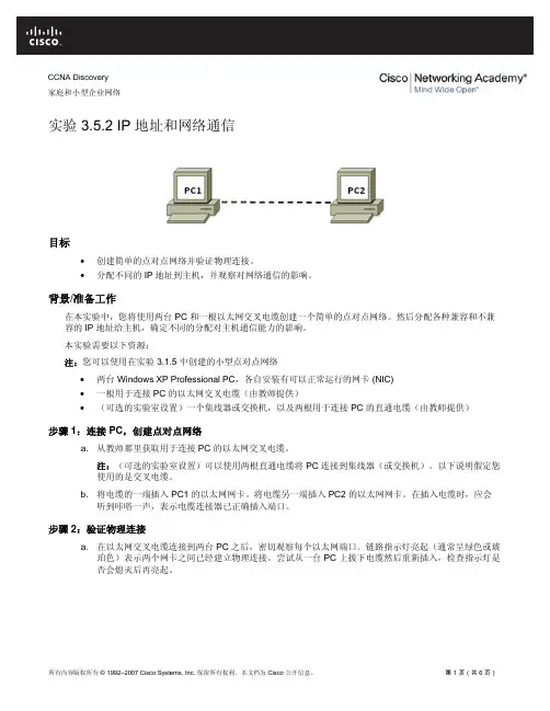
CCNA Discovery家庭和小型企业网络实验 3.5.2 IP 地址和网络通信目标•创建简单的点对点网络并验证物理连接。
•分配不同的 IP 地址到主机,并观察对网络通信的影响。
背景/准备工作在本实验中,您将使用两台 PC 和一根以太网交叉电缆创建一个简单的点对点网络。
然后分配各种兼容和不兼容的 IP 地址给主机,确定不同的分配对主机通信能力的影响。
本实验需要以下资源:注:您可以使用在实验 3.1.5 中创建的小型点对点网络•两台 Windows XP Professional PC,各自安装有可以正常运行的网卡 (NIC)•一根用于连接 PC 的以太网交叉电缆(由教师提供)•(可选的实验室设置)一个集线器或交换机,以及两根用于连接 PC 的直通电缆(由教师提供)步骤 1:连接 PC,创建点对点网络a. 从教师那里获取用于连接 PC 的以太网交叉电缆。
注:(可选的实验室设置)可以使用两根直通电缆将 PC 连接到集线器(或交换机)。
以下说明假定您使用的是交叉电缆。
b. 将电缆的一端插入 PC1 的以太网网卡。
将电缆另一端插入 PC2 的以太网网卡。
在插入电缆时,应会听到咔嗒一声,表示电缆连接器已正确插入端口。
步骤 2:验证物理连接a. 在以太网交叉电缆连接到两台 PC 之后,密切观察每个以太网端口。
链路指示灯亮起(通常呈绿色或琥珀色)表示两个网卡之间已经建立物理连接。
尝试从一台 PC 上拔下电缆然后重新插入,检查指示灯是否会熄灭后再亮起。
b. 转到控制面板,双击网络连接图标,确认本地区域连接已经建立。
下图所示为活动的本地区域连接。
如果物理连接有问题,Local Area Connection 图标上将会显示红色的X,并且显示文字网络电缆没有插好。
c. 如果 Local Area Connection 指示没有连接上,请重复步骤 1 和 2 进行故障排除,可能还需要向教师确认您使用的是以太网交叉电缆。

CCNA Discovery企业中的路由和交换简介实验 3.4.2 配置中继端口连接交换机目标•观察默认交换机的 VLAN 配置和操作。
•在交换机上配置静态 VLAN 。
•检查 VLAN 的配置和操作。
• 配置交换机之间的中继。
设备 主机名/接口 Fa0/0 或 网卡地址 VLAN1 地址 Switch 1 S1 不适用 172.16.1.1/24 Switch 2 S2 不适用 172.16.1.2/24 Host 1a 不适用 172.16.1.10/24 不适用 Host 1b 不适用 172.16.1.11/24 不适用 Host 2 不适用 172.16.1.12/24 不适用背景/准备工作本实验的主要内容是使用 Cisco IOS 命令为 Cisco 2960 交换机(或同类交换机)执行基本的 VLAN 配置。
其说明信息同样适用于其它交换机,但命令语法可能会有所差异。
根据交换机型号,接口标识可能有所不同。
例如,模块化交换机有多个插槽;因此快速以太网端口可能是 FastEthernet 0/1 或 FastEthernet 1/1,具体取决于插槽和端口。
本实验需要以下资源:•两台 Cisco 2960 交换机或同类交换机•两台基于 Windows 的计算机,其中装有终端仿真程序•至少一根 RJ-45 转 DB-9 连接器控制台电缆,用以配置交换机和路由器•三根直通以太网电缆,用以连接计算机和交换机•一根交叉以太网电缆,用以连接 S1 和 S2注意:确保已经擦除路由器和交换机的启动配置。
有关擦除交换机和路由器配置的说明,请参见 Academy Connection 中 Tools(工具)部分的 Lab Manual(实验手册)。
步骤 1:连接设备a. 用交叉电缆将 Switch 1 的 Fa0/1 接口连接到 Switch 2 的 Fa0/1 接口。
b. 用直通电缆将 Host 1a 的以太网接口连接到 Switch 1 的 Fa0/2 接口。
实验一:交换机的基本配置与Telnet远程登陆配置实验目标:掌握交换机的基本配置Telnet远程登陆配置实验项目:一公司新近一批交换机,再投入网络使用后要进行一些配置和管理,作为网络管理员请你给你初始配置:并支持远程登录管理(Telnet远程登陆配置)>用户模式#特权模式(conf)#全局模式(conf-if)#端口模式交换机配置如下:Switch>enableSwitch#configure terminalSwitch(config)#hostname aaaa(config)#enable password 123aa(config)#exitaa#configure terminalEnter configuration commands, one per line. End with CNTL/Z.aa(config)#line vty 0 4aa(config-line)#password 123456aa(config-line)#loginaa(config-line)#exitaa(config)#vlan 1aa(config-vlan)#exitaa(config)#interface vlan 1aa(config-if)#ip addaa(config-if)#ip address 192.168.1.100 255.255.255.0aa(config-if)#no shutdownaa(config-if)#exitaa(config)#interface FastEthernet 0/1aa(config-if)#aa(config-if)#exitaa(config)#ip default-gateway 192.168.1.1aa(config)#endaa#exit设置计算机ip地址为:192.168.1.100 网管:192.168.1.1实验结果:用命令实现以下操作:1.查看本机ip地址2.Ping 交换机地址3.Ping网关地址4.Ping本机地址5.远程登录交换机查看交换机运行信息实验二:交换机划分vlan设置实验目标:交换机划分vlan设置实验项目:某公司财务部和销售部的计算机通过两台交换机实现通讯,要求财务部和销售部内部的计算机可以互通,但为了安全期间要求财务部和销售部进行安全隔离,请做配置1.单个交换机划分vlanSwitch>enableSwitch#configure tSwitch#configure terminalEnter configuration commands, one per line. End with CNTL/Z.Switch(config)#hSwitch(config)#hostname aaaa(config)#vlan 1aa(config-vlan)#exitaa(config)#interface vlan 1aa(config-if)#ip address 192.168.1.100 255.255.255.0aa(config-if)#no shutdownaa(config-if)#exitaa(config)#ip default-gateway 192.168.1.1aa(config)#vlan 10aa(config-vlan)#exitaa(config)#vlan 20aa(config-vlan)#exitaa(config)#interface range fastEthernet 0/1-12aa(config-if-range)#switchport access vlan 10aa(config-if-range)#exitaa(config)#interface range fastEthernet 0/13-24aa(config-if-range)#switchport access vlan 20aa(config-if-range)#exitaa(config)#exitaa#实验结果:用命令实现以下操作:1,pc1 ip地址192.168.1.2 24 网管:192.168.1.1 端口接1-122,pc2 ip地址192.168.1.3 24 网管:192.168.1.1 端口接13-243,pc3 ip地址192.168.1.4 24 网管:192.168.1.1 端口接1-124,pc4 ip地址192.168.1.5 24 网管:192.168.1.1 端口接13-245,四台pc机相互ping6,Ping 交换机地址2.多交换机划分vlan 两台交换机配置一样Switch>enableSwitch#configure terminalEnter configuration commands, one per line. End with CNTL/Z.Switch(config)#hostname aaaa(config)#vlan 2aa(config-vlan)#exitaa(config)#vlan 3aa(config-vlan)#exitaa(config)#interface faa(config)#interface fastEthernet 0/1aa(config-if)#switchport access vlan 2aa(config-if)#exitaa(config)#interface fastEthernet 0/2aa(config-if)#switchport access vlan 3aa(config-if)#exitaa(config)#interface fastEthernet 0/24aa(config-if)#switchport mode trunkaa(config-if)#exitaa(config)#interface vlan 1aa(config-if)#ip address 192.168.1.100 255.255.255.0aa(config-if)#no shutdownaa(config-if)#exitaa(config)#ip default-gateway 192.168.1.1aa(config)#exitaa#实验结果:用命令实现以下操作:1,pc1 ip地址192.168.1.2 24 网管:192.168.1.1 端口接12,pc2 ip地址192.168.1.3 24 网管:192.168.1.1 端口接23,pc3 ip地址192.168.1.4 24 网管:192.168.1.1 端口接14,pc4 ip地址192.168.1.5 24 网管:192.168.1.1 端口接25,四台pc机相互ping6,Ping 交换机地址实验三:不同vlan之间的通讯一、实验目的1、理解多层交换机的路由原理2、了解多层交换机在实际网络中的常用配置3、回顾二层交换机VLAN 的划分方法4、进一步理解802.1Q 的原理和使用方法二、应用环境二层交换机属于接入层交换机,在二层交换机上根据连接用户的不同,划分了不同VLAN,有时候会出现同一个VLAN 处于不同的交换机上。
第1篇一、实验目的1. 掌握思科网络设备的配置方法,包括交换机、路由器等;2. 熟悉思科网络设备的连接方式,如VLAN、STP等;3. 了解思科网络设备的网络管理功能;4. 培养实际动手操作能力和网络规划能力。
二、实验环境1. 硬件设备:思科交换机、路由器、计算机等;2. 软件设备:思科Packet Tracer模拟软件;3. 实验拓扑:楼宇网络拓扑。
三、实验内容1. 交换机配置(1)交换机的基本配置:配置交换机名称、描述、管理IP地址等;(2)VLAN配置:创建VLAN,配置VLAN ID和名称,将端口划分到对应VLAN;(3)STP配置:配置生成树协议,防止网络环路。
2. 路由器配置(1)路由器的基本配置:配置路由器名称、描述、管理IP地址等;(2)静态路由配置:配置静态路由,实现不同网络之间的互通;(3)动态路由配置:配置OSPF路由协议,实现路由器之间的动态路由学习。
3. 网络管理(1)查看设备信息:查看交换机、路由器的配置信息、运行状态等;(2)配置设备监控:设置设备监控,实时查看网络流量、设备性能等;(3)配置设备备份:设置设备配置备份,防止设备配置丢失。
4. 楼宇网络规划(1)分析楼宇网络需求:了解楼宇网络规模、网络设备需求等;(2)设计网络拓扑:根据需求设计楼宇网络拓扑;(3)配置网络设备:根据拓扑图配置网络设备,实现楼宇网络互通。
四、实验步骤1. 使用Packet Tracer软件创建实验拓扑,包括交换机、路由器、计算机等设备;2. 配置交换机,包括基本配置、VLAN配置、STP配置等;3. 配置路由器,包括基本配置、静态路由配置、动态路由配置等;4. 配置网络管理,包括设备信息查看、设备监控、设备备份等;5. 分析楼宇网络需求,设计网络拓扑;6. 根据拓扑图配置网络设备,实现楼宇网络互通;7. 测试网络连通性,确保楼宇网络正常运行。
五、实验结果与分析1. 实验结果:通过配置交换机、路由器等设备,成功实现了楼宇网络的互通;2. 实验分析:在实验过程中,掌握了思科网络设备的配置方法,熟悉了网络规划与设计的基本步骤,提高了实际动手操作能力和网络规划能力。
CCNA Discovery家庭和小型企业网络实验 3.6.5 共享资源目标使用 Windows XP 完成以下任务:•共享文件和文件夹。
•映射网络驱动器。
背景/准备工作PC 联网的一个主要优点是能够与其他联网的用户共享信息。
您经常需要与朋友或同事共享数据,包括歌曲、提议、度假照片等等。
映射驱动器经常和共享文件夹结合使用,因为驱动器映射可让用户快速访问常用文件夹,还可以提供一种更为简便的方式让用户浏览和查找所需的文件和(或)文件夹。
驱动器映射将本地资源(驱动器盘符)重定向到共享的网络资源(网络上的硬盘或文件夹)。
本实验需要以下资源:•两个通过本地网络连接并且已经配置好的 Windows XP Professional 工作站。
注:可以使用前面的实验练习 3.6.5 中配置的网络。
步骤 1:共享文件夹a. 单击开始。
从“开始”菜单中依次选择所有程序、附件和Windows 资源管理器。
b. 在“文件夹”窗格中,单击我的电脑旁边的加号 (+)。
单击C:驱动器。
从文件菜单中选择新建,然后从子菜单中选择文件夹选项。
键入Share 作为文件夹的名称。
c. 右键单击新文件夹Share并选择属性。
注:Documents and Settings、Program Files 和 Windows 系统文件夹中无法使用“共享”选项。
d. 选择共享选项卡。
在“share 属性”对话框中,单击共享此文件夹单选按钮以与网络中的其他用户共享该文件夹。
共享文件夹的默认名称就是原始文件夹名称。
注:要更改网络上文件夹的名称,请在“共享名”文本框中键入新名称。
您计算机上的该文件夹名称不会因此而改变。
e. 依次单击应用和确定。
f. 用记事本创建一个文本文件并存储到 Share 文件夹中。
在 Windows XP 桌面上,单击开始,然后依次选择所有程序、附件和记事本。
在记事本应用程序中,键入消息 “Hello World!”。
从文件菜单中选择保存。
高级网络技术实验报告一、实验目的(本次实验所涉及并要求掌握的知识点)8.2 实验1:把一台Cisco 路由器配置为帧中继交换机①理解帧中继交换机的工作原理;②理解PVC 的概念;③用路由器充当帧中继交换机的配置。
8.5 实验4:帧中继点到多点子接口通过本实验,读者可以掌握点到多点子接口的配置这项技能。
4.2.1.4 配置静态帧中继映射第1 部分:配置帧中继第2 部分:配置静态帧中继映射和LMI 类型4.2.2.6 配置帧中继点对点子接口第1 部分:配置帧中继第2 部分:配置帧中继点对点子接口第3 部分:检验配置和连接二、实验内容与设计思想(设计思路、主要数据结构、主要代码结构)8.5 实验4:帧中继点到多点子接口在实验1的基础上进行。
4.2.2.6 配置帧中继点对点子接口三、实验使用环境(本次实验所使用的平台和相关软件)WIN10Cisco Packet Tracer四、实验步骤和调试过程(实验步骤、测试数据设计、测试结果分析)8.2 实验1:把一台Cisco 路由器配置为帧中继交换机R1(config-if)#exR2:(1)步骤1:开启帧中继交换功能R2(config)frame-relay switching //把该路由器当成帧中继交换机(2)步骤2:配置接口封装R2(config)#int s0/0R2(config-if)#no shutdownR2(config-if)#clock rate 128000 该接口为DCE,要配置时钟R2(config-if)#encapsulation frame-relayR2(config)#int s0/1R2(config-if)#no shutdownR2(config-if)#clock rate 128000R2(config-if)#encapsulation frame-relayR2(config)#int s1/0R2(config-if)#no shutdownR2(config-if)#clock rate 128000R2(config-if)#encapsulation frame-relay(3)步骤3:配置LMI 类型R2(config)int s0/0R2(config-if)frame-relay lmi-type ciscoR2(config-if)frame-relay intf-type dceR2(config)int s0/1R2(config-if)frame-relay lmi-type ciscoR2(config-if)frame-relay intf-type dceR2(config)int s1/0R2(config-if)frame-relay lmi-type ciscoR2(config-if)frame-relay intf-type dce(4)步骤4:配置帧中继交换表R3:R3(config-if)#ex实验调试(1)可以使用”show frame-relay route”,”show frame pvc”和”show frame lmi”等命令检查帧中继交换机是否正常show frmae-relay routeshow frame pvcshow frame lmi8.5 实验4:帧中继点到多点子接口在实验1的基础上进行。
实验1 路由器基础命令回顾一、实验目的通过本节的练习回顾、熟悉一期课程中涉及到的路由器的相关指令。
掌握路由器的基础配置。
二、实验需要的知识点一期路由器的基础知识。
三、实验步骤1、改写主机名。
把路由器的主机名改成:RouterA. 。
在全局模式下使用指令的关键字:hostname name2、配置密码。
进入特权模式的密码为cisco。
配置控制台的密码:cisco配置远程登录的密码:cisco在全局模式下使用指令的关键字:enable password password在全局模式下使用指令的关键字:line vty 0 4loginpassword password在全局模式下使用指令的关键字:line console 0loginpassword password3、配置时钟。
在全局模式下使用指令的关键字:clock set hh::mm::ss mm:dd:yy4、配置接口ip地址。
在路由器的环回接口配置ip地址:1.1.1.1/24 。
在e0接口上配置ip地址:192.1.1.1/24在全局模式下使用指令的关键字:interface interface在接口模式下使用指令的关键字:ip address ip address mask5、退出,有三种方法。
endexitlogout6、保存配置,有两种方法。
copy running-config stratup-configwrite7、停止域名解析查询。
在全局模式下使用指令的关键字:no ip domain lookup四、检测在特权模式下使用:show version2、在特权模式下使用:show interface {interface}3、在特权模式下使用:show flash4、在特权模式下使用:show running-config5、在特权模式下使用:show startup-config6、在特权模式下使用:show history7、在特权模式下使用:show clock8、ping 自己的环回口地址。
目录使用帮助 (1)1.计算机命令: (1)2.交换机支持的命令: (1)3.路由器支持的命令: (2)4.PIX防火墙命令 (6)理论学习 (7)网络的发展与应用 (7)网络互联基础 (8)交换机原理与应用 (13)路由器原理与应用 (17)常见广域网协议及特点 (23)PIX防火墙特点与应用 (24)五、PIX防火墙举例 (29)PIX防火墙应用举例 (29)常见操作操作错误: (31)实验一口令和主机名设置 (31)实验二计算机与交换机IP地址设置 (36)实验三交换机VLAN实验 (38)实验四路由器的升级 (41)实验五路由器接口ip及直联路由 (44)实验六一个vlan下的单臂路由 (46)实验七子接口单臂路由 (48)实验八静态路由 (50)实验九动态路由 (53)实验十交换机和路由器组合实验 (56)实验十一访问控制列表 (59)实验十二综合实验 (62)实验十三《三层交换机实验》 (64)实验十四《三层交换与二层交换机结合》 (66)实验十五《三层交换机与路由器的连接》 (67)实验十六《交换机的通道技术》 (68)实验十七《交换机与路由器间的端口聚合》 (70)实验十八《静态NAT配置》 (71)实验十九《常见NAT配置》 (72)实验二十防火墙设置 (75)实验二十一点到点联接时OSPF的配置 (77)实验二十二广播方式的OSPF配置 (79)实验二十三非广播方式的OSPF配置 (80)实验二十四PPP配置实验 (82)实验二十五实验室条件下点对点帧中继配置 (83)实验二十六点对点的帧中继配置 (84)实验二十七子接口帧中继配置 (85)实验二十八配置BGP (87)实验二十九GRE VPN的配置 (88)实验三十ipsec site-to-site VPN配置 (90)使用帮助1.计算机命令:PCAlogin:root;使用root用户password:linux;口令是linux#shutdown-hnow;同init0关机#logout;退出登录#login;登录#ifconfig;显示IP地址#ifconfigeth0<ipaddress>netmask<netmask>;设置IP地址#ifconfigeth0<ipaddress>netmask<netmask>down;删除IP地址#routeadd0.0.0.0gw<ip>;设置网关#routedel0.0.0.0gw<ip>;删除网关#routeadddefaultgw<ip>;设置网关#routedeldefaultgw<ip>;删除网关#route;显示网关#ping<ip>;测试网络#telnet<ip>;远程登录2.交换机支持的命令:交换机基本状态:switch:;交换机的ROM状态rommon>;路由器的ROM状态hostname>;用户模式hostname#;特权模式hostname(config)#;全局配置模式hostname(config-if)#;接口状态交换机口令设置:switch>enable;进入特权模式switch#configterminal;进入全局配置模式switch(config)#hostname<hostname>;设置交换机的主机名switch(config)#enablesecretxxx;设置特权加密口令switch(config)#enablepasswordxxa;设置特权非密口令switch(config)#lineconsole0;进入控制台口switch(config-line)#linevty04;进入虚拟终端switch(config-line)#login;允许登录switch(config-line)#passwordxx;设置登录口令xxswitch#exit;返回命令交换机VLAN设置:switch#vlandatabase;进入VLAN设置switch(vlan)#vlan2;建VLAN2switch(vlan)#novlan2;删vlan2switch(vlan)#vtpdomain<name>;设置发vtp域名switch(vlan)#vtppassword<word>;设置发vtp密码switch(vlan)#vtpserver;设置发vtp模式switch(vlan)#vtpclient;设置发vtp模式switch(vlan)#vtppruning;设置vtp允许switch(config)#intf0/1;进入端口1switch(config-if)#switchportaccessvlan2;当前端口加入vlan2switch(config-if)#switchportmodetrunk;设置为干线switch(config-if)#switchporttrunkallowedvlan1,2;设置允许的vlanswitch(config-if)#switchporttrunkencapdot1q;设置vlan中继switch(config-if)#speed;设置接口速度switch(config-if)#duplex;设置接口作方式交换机设置IP地址:switch(config)#interfacevlan1;进入vlan1switch(config-if)#ipaddress<IP><mask>;设置IP地址switch(config)#ipdefault-gateway<IP>;设置默认网关switch#dirflash:;查看闪存交换机显示命令:switch#write;保存配置信息switch#showvtp;查看vtp配置信息switch#showrun;查看当前配置信息switch#showvlan;查看vlan配置信息switch#showinterface;查看端口信息switch#showintf0/0;查看指定端口信息3.路由器支持的命令:路由器显示命令:router#showrun;显示配置信息router#showinterface;显示接口信息router#showiproute;显示路由信息router#showcdpnei;显示邻居信息router#reload;重新起动路由器口令设置:router>enable;进入特权模式router#configterminal;进入全局配置模式router(config)#hostname<hostname>;设置交换机的主机名router(config)#enablesecretxxx;设置特权加密口令router(config)#enablepasswordxxb;设置特权非密口令router(config)#lineconsole0;进入控制台口router(config-line)#linevty04;进入虚拟终端router(config-line)#login;要求口令验证router(config-line)#passwordxx;设置登录口令xxrouter(config)#(Ctrl+z);返回特权模式router#exit;返回命令路由器配置:router(config)#ints0/0;进入Serail接口router(config-if)#noshutdown;激活当前接口router(config-if)#clockrate64000;设置同步时钟router(config-if)#ipaddress<ip><netmask>;设置IP地址router(config-if)#ipaddress<ip><netmask>second;设置第二个IProuter(config-if)#intf0/0.1;进入子接口router(config-subif.1)#ipaddress<ip><netmask>;设置子接口IProuter(config-subif.1)#encapsulationdot1q<n>;绑定vlan中继协议router(config)#config-register0x2142;跳过配置文件router(config)#config-register0x2102;正常使用配置文件router#reload;重新引导路由器文件操作:router#copyrunning-configstartup-config;保存配置router#copyrunning-configtftp;保存配置到tftprouter#copystartup-configtftp;开机配置存到tftprouter#copytftpflash:;下传文件到flashrouter#copytftpstartup-config;下载配置文件ROM状态:Ctrl+Break;进入ROM监控状态rommon>confreg0x2142;跳过配置文件rommon>confreg0x2102;恢复配置文件rommon>reset;重新引导rommon>copyxmodem:<sname>flash:<dname>;从console传输文件rommon>IP_ADDRESS=10.65.1.2;设置路由器IPrommon>IP_SUBNET_MASK=255.255.0.0;设置路由器掩码rommon>TFTP_SERVER=10.65.1.1;指定TFTP服务器IPrommon>TFTP_FILE=c2600.bin;指定下载的文件rommon>tftpdnld;从tftp下载rommon>dirflash:;查看闪存内容rommon>boot;引导IOS静态路由:iproute<ip-address><subnet-mask><gateway>;命令格式router(config)#iproute2.0.0.0255.0.0.01.1.1.2;静态路由举例router(config)#iproute0.0.0.00.0.0.01.1.1.2;默认路由举例动态路由:router(config)#iprouting;启动路由转发router(config)#routerrip;启动RIP路由协议。
router(config-router)#network<netid>;设置发布路由router(config-router)#negihbor<ip>;点对点帧中继用。
帧中继命令:router(config)#frame-relayswitching;使能帧中继交换router(config-s0)#encapsulationframe-relay;使能帧中继router(config-s0)#fram-relaylmi-typecisco;设置管理类型router(config-s0)#frame-relayintf-typeDCE;设置为DCErouter(config-s0)#frame-relaydlci16;router(config-s0)#frame-relaylocal-dlci20;设置虚电路号router(config-s0)#frame-relayinterface-dlci16;router(config)#log-adjacency-changes;记录邻接变化router(config)#ints0/0.1point-to-point;设置子接口点对点router#showframepvc;显示永久虚电路router#showframemap;显示映射基本访问控制列表:router(config)#access-list<number>permit|deny<source_ip><wild|any>router(config)#interface<interface>;default:denyanyrouter(config-if)#ipaccess-group<number>in|out;default:out例1:router(config)#access-list1denyhost10.65.1.1router(config)#access-list1permitanyrouter(config)#intf0/0router(config-if)#ipaccess-group4in例2:router(config)#access-list4permit10.8.1.1router(config)#access-list4deny10.8.1.00.0.0.255router(config)#access-list4permit10.8.0.00.0.255.255router(config)#access-list4deny10.0.0.00.255.255.255router(config)#access-list4permitanyrouter(config)#intf0/1router(config-if)#ipaccess-group4in扩展访问控制列表:access-list<number>permit|denyicmp<S_IPwild><D_IPwild>[type]access-list<number>permit|denytcp<S_IPwild><D_IPwild>[port]例1:router(config)#access-list101denyicmpany10.64.0.20.0.0.0echorouter(config)#access-list101permitipanyanyrouter(config)#ints0/0router(config-if)#ipaccess-group101in例2:router(config)#access-list102denytcpany10.65.0.20.0.0.0eq80router(config)#access-list102permitipanyanyrouter(config)#interfaces0/1router(config-if)#ipaccess-group102out删除访问控制例表:router(config)#noaccess-list102router(config-if)#noipaccess-group101in路由器的nat配置Router(config-if)#ipnatinside;当前接口指定为内部接口Router(config-if)#ipnatoutside;当前接口指定为外部接口Router(config)#ipnatinsidesourcestatic[p]<私有IP><公网IP>[port]Router(config)#ipnatinsidesourcestatic10.65.1.260.1.1.1Router(config)#ipnatinsidesourcestatictcp10.65.1.38060.1.1.180Router(config)#ipnatpoolp160.1.1.160.1.1.20255.255.255.0Router(config)#ipnatinsidesourcelist1poolp1Router(config)#ipnatinsidedestinationlist2poolp2Router(config)#ipnatinsidesourcelist2interfaces0/0overloadRouter(config)#ipnatpoolp210.65.1.210.65.1.4255.255.255.0typerotaryRouter#showipnattranslationrotary参数是轮流的意思,地址池中的IP轮流与NAT分配的地址匹配。