
U3-B-LP
- 格式:ppt
- 大小:387.00 KB
- 文档页数:16


常规LVDS接口液晶屏定义20PIN单6定义:1:电源2:电源3:地 4:地 5:R0- 6:R0+ 7:地 8:R1- 9:R1+ 10:地 11:R2- 12:R2+ 13:地 14:CLK- 15:CLK+ 16空 17空 18空 19 空 20空每组信号线之间电阻为(数字表120欧左右)20PIN双6定义:1:电源2:电源3:地 4:地 5:R0- 6:R0+ 7:R1- 8:R1+ 9:R2- 10:R2+ 11:CLK- 12:CLK+ 13:RO1- 14:RO1+ 15:RO2- 16:RO2+ 17:RO3- 18:RO3+ 19:CLK1- 20:CLK1+每组信号线之间电阻为(数字表120欧左右)20PIN单8定义:1:电源2:电源3:地 4:地 5:R0- 6:R0+ 7:地 8:R1- 9:R1+ 10:地 11:R2- 12:R2+ 13:地 14:CLK- 15:CLK+ 16:R3- 17:R3+每组信号线之间电阻为(数字表120欧左右)30PIN单6定义:1:空2:电源3:电源 4:空 5:空 6:空 7:空 8:R0- 9:R0+ 10:地 11:R1- 12:R1+ 13:地 14:R2- 15:R2+ 16:地 17:CLK- 18:CLK+ 19:地 20:空- 21:空 22:空 23:空 24:空 25:空 26:空 27:空 28空 29空 30空每组信号线之间电阻为(数字表120欧左右)30PIN单8定义:1:空2:电源3:电源 4:空 5:空 6:空 7:空 8:R0- 9:R0+ 10:地 11:R1- 12:R1+ 13:地 14:R2- 15:R2+ 16:地 17:CLK- 18:CLK+ 19:地 20:R3- 21:R3+ 22:地 23:空 24:空 25:空 26:空 27:空 28空 29空 30空每组信号线之间电阻为(数字表120欧左右)30PIN双6定义:1:电源2:电源3:地 4:地 5:R0- 6:R0+ 7:地 8:R1- 9:R1+ 10:地 11:R2- 12:R2+ 13:地 14:CLK- 15:CLK+ 16:地 17:RS0- 18:RS0+ 19:地 20:RS1- 21:RS1+ 22:地 23:RS2- 24:RS2+ 25:地 26:CLK2- 27:CLK2+每组信号线之间电阻为(数字表120欧左右)30PIN双8定义:1:电源2:电源3:电源 4:空 5:空 6:空 7:地 8:R0- 9:R0+ 10:R1- 11:R1+ 12:R2- 13:R2+ 14:地 15:CLK- 16:CLK+ 17:地 18:R3- 19:R3+ 20:RB0-21:RB0+ 22:RB1- 23:RB1+ 24:地 25:RB2- 26:RB2+ 27:CLK2- 28:CLK2+ 29:RB3- 30:RB3+每组信号线之间电阻为(数字表120欧左右)一般14PIN、20PIN、30PIN为LVDS接口。

∙ Low profile package saves space ∙ Designed for use in hazardous areas ∙ Excellent resistance to shock and vibration∙ 30mm standard through shaft, PEEK reduction hub available ∙ Hard anodized housing and high protection level of IP66 ∙ High performance in temperatures from –40°C to +85°C ∙ Reinforced SSI output∙ Wiring fault tolerant & 60Vdc overvoltage protection ∙Resolution up to 16 bitsMechanical Characteristics:MaterialCover : Hard anodized aluminumVibrations (EN60068-2-6) ≤ 200m.s -2(55 … 2 000 Hz) Body : Hard anodized aluminum Shaft inertia< 130 000 g.mm 2 Shaft : AISI 303 stainless steelStatic/Dynamic torque30 / 300 mN.m Ball bearings6807 - Sealed Continuous max. speed*6000 min -1Maximum loadsAxial: 40 NTheoretical mechanical lifetime L 10h** > 18.109 turns / 100000 hours Radial: 80 NEncoder weight (approx.) 1.6 kgShocks (EN60068-2-27)≤ 3000m.s -2 (during 5 ms)** Continuous max. Speed – ½ max. load – ISO 281, L 10* The temperature given on the following chart has to be added to the ambient temperature. The total must never exceed the maximum T°C given by the datasheet.These temperature elevations are typical values which should be considered as indications only.Available mechanics – shaft options:Specification sheet AH_X - P/N 2000/009 Rev. A 1/4Output:Serial Synchronous Interface SSI output provides effectivesynchronisation in a closed-loop control system. A clock pulse train from a controller is used to shift out sensor sensor data: one bit of position data is transmitted to the controller per clock pulse received by the sensor.AHUX: Through Hollow ShaftAHKX: Blind Hollow ShaftAHAX: Shaft with Integrated couplingAHMX: Solid ShaftCertifications:The LP Incremental Encoder is available with the following certificationsEx d IIB T4 GbCENELECII 2 G Ex d IIB T4 Gb2004/108/CEU.S. / Canadian Class I, Group C & DDEMKO 16 ATEX 1691X rev.0IECEx UL 16.0064X Issue 0 E78446DimensionsAHUX – Through hollow shaftDimensions AHKX – Blind hollow shaftSpecification sheet AH_X - P/N 2000/009 Rev. A 2/4Floating MountingsBall end tether arm:P/N :M9230-03/xxx xxx = length in mmNote : CHc : Hexagonal socket head cap screws (recommended torque clamp screw CHc M4=3,5N.m, and Terminal Box CHc M6=6,5N.m)HC : Hexagonal socket set screws (recommended torque Hc M6 : 2,5N.m)LP seriesExplosion-proof and Flameproof Absolute EncoderDimensionsAHAX – Shaft with integrated couplingDimensions AHMX – Solid shaftSpecification sheet AH_X - P/N 2000/009 Rev. A 3/4Flange MountingsUL – ATEX – IECEx certifiedLP seriesExplosion-proof and Flameproof Absolute EncoderElectrical Characteristics:VersionOutput signalsResolution Operating Voltage Vcl Supplycurrent(no loads)Currentper channel pairMax Frequency capabilityEncoder accuracy Short circuitsproof Reverse polarity tolerant Wiring faulttolerant &60VdcovervoltageprotectionTemperaturerangePSRRS422up to 16 BITS5-30V 75mA 40mA 1MHz +/-0.1°Yes (except toVcl)YesYes-40°C +85°CPSSNoTYPE:BORE:OUTPUT:CODE:PER TURN: OUTPUT TERMINATION:LENGTH:HUB:AHUX = hollow shaftE5 = 5/8’’ E6 = 3/4’’ E8 = 1‘’ 30 = 30mmPSR = 5-30V voltageandreinforced SSIoutput (without parity)PSS = 5-30V voltageand SSI output (without parity)B = Binary (CCW increasing code) G = Gray (CCW increasing code)(Enter bits)See available resolutions aboveSKR = M16 cable-glandwith PUR cablexxx = cable lengthex 020 = 2metersU3 = With insulated sleeveAHKX = blind shaftE0R = M16 radial terminal box (without cable-gland)E4R = 1/2’’ NPT radial terminal box (withoutcable-gland)E6R = 3/4’’ NPT radial terminal box (withoutcable-glandBlank = No cableAHAX = hollow shaftwith integrated coupling E6 = 3/4’’ 14 = 14mm 20 = 20mmU5 = Blind sleeve U6 = Through sleeveAHMX = solid shaft E3 = 3/8’’ 12 = 12mm** = no sleeveStainless steel option available.Anti-rotation accessory: M9230-03/xxx Ball end tether arm (xxx = length in mm) to be ordered separately.Specification sheet AH_X - P/N 2000/009 Rev. A 4/4BEI SENSORS Europe 9, rue de CopenhagueEspace Européen de l’Entreprise-Schiltigheim BP 70044 - 67013 STRASBOURG Cedex FranceTel: +33 (0)3-88-20-80-80 | Fax: +33 (0)3-88-20-87-87 email:*******************BEI SENSORS North America1461 Lawrence Dr | Thousand Oaks, CA 91320 USA Tel: 800-350-2727 or 805-968-0782 Fax: 800-960-2726 or 805-968-3154 email:***********************UL – ATEX – IECEx certifiedLP seriesExplosion-proof and Flameproof EncoderSPECIAL CONDITIONS FOR SAFE USE:None required.The gaps of the different flame paths are less than the values specified in the tables of the IEC 60079-1 standard.The width of the different flameproof joints are superior to these specified in tables of IEC 60079-1 standard. See Document 08329-001 for construction details.ASSEMBLY CAUTION/WARNING:Keep terminal cover closed and cable gland secured while in presence of hazardous atmosphere.Open all circuits to this product prior to removal of terminal block cover.Electrical installation shall use standard EN/IEC 60079-14 and/or NEC Class 2 circuit specifications. UL certified installations require the use of a sealing fitting certified to 60079-0 Ex d IIB within 18 in. (46 cm) of the encoder. Terminal block covers are marked near the threaded hole with the basic thread size to aid with selection of fittings or glands. Conductor insulation must be rated for at least 105°C ambient temperature. External case ground connection is provided by means of a screw and ring type terminal which accepts up to 10 AWG (5.26 mm 2) size conductor.The customer shall use our products according to our specifications and to the manners of the profession. BEI Sensors will not be responsible for any defect resulting from improper installation or from operating outside of the specification limits of the product. Malfunctions caused by excessive shocks, bad electric supply, under or over voltage, the environmental conditions outside of the design specifications, are not covered by warranty. The encoder doesn’t require any maintenance. There are no user serviceable parts inside. Any defective encoder shall be returned to the nearest BEI Sensors facility for evaluation and repair/replacement. A high integrity case ground connection must be made at or near the encoder installation location.See LP series User Manual for installation details and Specification Documents (no. 2000/008 or 2000/009) for product details not otherwise indicated on this document.EU Declaration of Conformity1. We, BEI Sensors, certify that Models HH_X and AH_X all resolutions, channel and output type options are explosion proof and flame proofas noted on the UL, IECEX and DEMKO certificates cited below.2. With the following marking: II 2 G Ex d IIB T4 Gb3. Designed and manufactured to comply with these directives:ATEX : 2014/34/EU and CEM : 2014/30/EU4. Complies with these standards:ATEX: EN60079-0:2012+A11:2013, EN60079-1:2014, IECEx: IEC60079-0:2011+IS1 2013, IEC60079-1:20145. As detailed in EC type examination certificates:DEMKO 16 ATEX 1691X rev.0 and IECEx UL 16.0064X Issue 0 Product Quality Assurance Notification: LCIE 03 ATEX Q8060Product Quality Assurance Report : FR/LCI/QAR08 00026. EMC: The following standards were also investigated for this certification: NFC 23-520, NFC 23-539, EN 50081-1, EN 55022 classe B, EN55014, EN 61000-6-2, CEI 61000-4-2, CEI 61000-4-3, CEI61000-4-4, CEI 61000-4-5, CEI 61000-4-6, CEI 61000-4-8, CEI61000-4-117. The notified organization responsible for the follow-up of the ATEX directive is (Assessed by): LCIE, B.P.8, F92260 Fontenay-aux-Roses - Identification number: 00818. The company in charge of certification CEM is: LCIE BUREAU VERITAS, Aire de la Thur 68840 PulversheimUL Declaration of ConformityPart number Model HH_X and AH_X model for use in Class I, Group C & DUL 1203 Explosion-Proof and Dust-Ignition-Proof Electrical Equipment for Use in Hazardous (Classified) Locations C22.2 No. 30-M1986 - Explosion-Proof Enclosures for Use in Class I Hazardous Locations UL Certificate No. E78446The notified organization responsible for the follow-up inspections for thisUL listing is (Assessed by):UL International (France) SAEspace Technologique de Saint-Aubin, Immeuble Explorer Route de l’Orme des Merisiers – F-91190 SAINT AUBIN: Identification number: 675Installation sheet HH_X/AH_X - P/N 2000/040 Rev. A 1/2UL – ATEX – IECEx certifiedUnscrew the 3 CHc M6 screws to remove the connection boxSlide right to unlock Connector WiringAlign Bumps and Notches to takeConnector outPrepare the wires Tighten Pressure screwCrimp the wires and screw it on connectorAlign Bumps and Notches and push-inSlide left to lock connector in placePut Connection box in place and screw 3 CHc screws on recommended torqueInstallation sheet HH_X/AH_X - P/N 2000/040 Rev. A 2/2Copyright © 2023 Sensata Technologies, Inc.Datasheets provided by Sensata Technologies, Inc., its subsidiaries and/or affiliates (“Sensata”) are solely intended to assist third parties (“Buyers”) who are developing systems that incorporate Sensata products (also referred to herein as “components”). Buyer understands and agrees that Buyer remains responsible for using its independent analysis, valuation, and judgment in designing Buyer’s systems and products. Sensata datasheets have been created using standard laboratory conditions and engineering practices. Sensata has not conducted any testing other than that specifically described in the published documentation for a particular datasheet. Sensata may make corrections, enhancements, improvements, and other changes to its datasheets or components without notice.Buyers are authorized to use Sensata datasheets with the Sensata component(s) identified in each particular datasheet. HOWEVER, NO OTHER LICENSE, EXPRESS OR IMPLIED, BY ESTOPPEL OR OTHERWISE TO ANY OTHER SENSATA INTELLECTUAL PROPERTY RIGHT, AND NO LICENSE TO ANY THIRD PARTY TECHNOLOGY OR INTELLECTUAL PROPERTY RIGHT, IS GRANTED HEREIN. SENSATA DATASHEETS ARE PROVIDED “AS IS”. SENSATA MAKES NO WARRANTIES OR REPRESENTATIONS WITH REGARD TO THE DATASHEETS OR USE OF THE DATASHEETS, EXPRESS, IMPLIED, OR STATUTORY , INCLUDING ACCURACY OR COMPLETENESS. SENSATA DISCLAIMS ANY WARRANTY OF TITLE AND ANY IMPLIED WARRANTIES OF MERCHANTABILITY , FITNESS FOR A PARTICULAR PURPOSE, QUIET ENJOYMENT, QUIET POSSESSION, AND NON-INFRINGEMENT OF ANY THIRD PARTY INTELLECTUAL PROPERTY RIGHTS WITH REGARD TO SENSATA DATASHEETS OR USE THEREOF.All products are sold subject to Sensata’s terms and conditions of sale supplied at .SENSATA ASSUMES NO LIABILITY FOR APPLICATIONS ASSISTANCE OR THE DESIGN OF BUYERS’ PRODUCTS. BUYER ACKNOWLEDGES AND AGREES THAT IT IS SOLELY RESPONSIBLE FOR COMPLIANCE WITH ALL LEGAL, REGULATORY , AND SAFETY-RELATED REQUIREMENTS CONCERNING ITS PRODUCTS, AND ANY USE OF SENSATA COMPONENTS IN ITS APPLICATIONS, NOTWITHSTANDING ANY APPLICATIONS-RELATED INFORMATION OR SUPPORT THAT MAY BE PROVIDED BY SENSATA.Mailing Address: Sensata Technologies, Inc., 529 Pleasant Street, Attleboro, MA 02703, USARegional head offices:United States of America Sensata Technologies Attleboro, MAPhone: 508-236-3800E-mail:*******************NetherlandsSensata Technologies Holland B.V.HengeloPhone: +31 74 357 8000E-mail:*******************ChinaSensata Technologies China Co., Ltd.ShanghaiPhone: +8621 2306 1500E-mail: *******************CONTACT US。
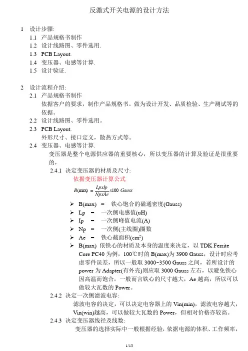
1 设计步骤:1.1 产品规格书制作1.2 设计线路图、零件选用.1.3 PCB Layout.1.4 变压器、电感等计算.1.5 设计验证.2 设计流程介绍:2.1 产品规格书制作依据客户的要求,制作产品规格书。
做为设计开发、品质检验、生产测试等的依据。
2.2 设计线路图、零件选用。
2.3 PCB Layout.外形尺寸、接口定义,散热方式等。
2.4 变压器、电感等计算.变压器是整个电源供应器的重要核心,所以变压器的计算及验证是很重要的,2.4.1 决定变压器的材质及尺寸:依据变压器计算公式Gauss x NpxAeLpxIp B 100(max ) ➢ B(max) = 铁心饱合的磁通密度(Gauss)➢ Lp = 一次侧电感值(uH)➢ Ip = 一次侧峰值电流(A)➢ Np = 一次侧(主线圈)圈数➢ Ae = 铁心截面积(cm 2)➢B(max) 依铁心的材质及本身的温度来决定,以TDK FerriteCore PC40为例,100℃时的B(max)为3900 Gauss ,设计时应考虑零件误差,所以一般取3000~3500 Gauss 之间,若所设计的power 为Adapter(有外壳)则应取3000 Gauss 左右,以避免铁心因高温而饱合,一般而言铁心的尺寸越大,Ae 越高,所以可以做较大瓦数的Power 。
2.4.2 决定一次侧滤波电容:滤波电容的决定,可以决定电容器上的Vin(min),滤波电容越大,Vin(win)越高,可以做较大瓦数的Power ,但相对价格亦较高。
2.4.3 决定变压器线径及线数:变压器的选择实际中一般根据经验,依据电源的体积、工作频率,散热条件,工作环境温度等选择。
当变压器决定后,变压器的Bobbin 即可决定,依据Bobbin 的槽宽,可决定变压器的线径及线数,亦可计算出线径的电流密度,电流密度一般以6A/mm 2为参考,电流密度对变压器的设计而言,只能当做参考值,最终应以温升记录为准。