新型燃气热水锅炉说明书
- 格式:pdf
- 大小:691.47 KB
- 文档页数:19
WNSI用全自动燃气.油热水锅炉安装使用说明书一、系统设计概况二、锅炉参数及辅机三、锅炉自控简介(详见电控箱说明书、电路图)四、锅炉安装指导篇4.1 . 说明4.2 . 安装的般注意事项4.3 . 安装前的准备工作4.4 . 基本尺寸(详见出厂随机技术资料)4.5 . 锅炉参数(详见出厂随机技术资料)4.6 . 安全方面4.7.锅炉安装基准4.8 . 管道安装4.9 . 锅炉整体水压试验4.10 .保温施工及油漆4.11 .电气安装4.12 .烟囱的施工4.13 .燃烧器安装4.14 .锅炉前门安装调整4.15 .安全阀的调整4.16 .煮炉4.17 .试运行4.18.总体验收五、锅炉使用说明篇5.1.安全方面5.2运行5.3定期检验和检验方法5.4水质标准5.5锅炉故障对策表5.6燃烧器5.7控制盘六、锅炉经济运行七、附言、系统设计概况WNS通用系列湿背全自动燃气 .油热水锅炉系卧式内燃三回程火管锅炉,采用低位、对称布置燃烧室,本体上所有管子与锅筒及管板连接均采用焊接形式。
前 烟箱采用快开结构,回火室后部装有防爆、检查于一体的防爆门,锅筒下部设两 个头孔和清灰孔,便于检测、维修和清理。
锅炉采用下置波纹炉胆,高温烟气经 波纹炉胆回火室依次冲刷第二及第三回程烟管,然后由后烟室经烟囱排入大气。
该锅炉配有先进全自动燃烧机,选用上乘的国产阀门、仪表、水泵。
锅炉点火、 燃烧给水、安全保护等均属自动控制。
该锅炉具有安全可靠、效率高、造型美观、 结构紧凑、安装简便、经久耐用等优点,适宜于各行业生产、生活供汽用。
WNSS用系列热水锅炉湿背全自动燃气 •油热水锅炉集中了国内外同类型锅炉之精萃,无 论是锅炉内部结构还是外型设计均处于同行业之领先地位。
附系统供热流程图:1、锅炉参数及辅机见图纸三、锅炉自控简介(详见电控箱说明书、电路 图)自控系统由燃烧控制、给水控制、压力保护、水位保护等控制电路组成,实 现锅炉的自动点火,燃烧、负荷调节、自动给水、安全运行。
家用燃煤气化采暖炉使用说明书尊敬的用户:感谢您选择和使用我们的家用燃煤气化采暖炉。
为了确保您能够安全、正确地使用本产品,充分发挥其性能,为您的家庭提供温暖舒适的环境,请您在使用前仔细阅读本使用说明书。
一、产品概述家用燃煤气化采暖炉是一种高效、节能的取暖设备,它采用先进的气化燃烧技术,能够将煤气充分燃烧,提高能源利用率,为您的家庭提供稳定的热量。
本采暖炉具有操作简单、使用方便、安全可靠等优点。
二、产品规格及技术参数1、型号:_____2、额定热功率:_____kW3、供暖面积:_____平方米4、燃料类型:煤气5、热效率:_____%6、排烟温度:_____℃三、安装注意事项1、安装位置选择采暖炉应安装在通风良好、干燥的室内,远离易燃、易爆物品。
安装位置应便于操作和维护,且周围要有足够的空间。
禁止在卧室、浴室等潮湿或密闭的空间安装。
2、烟囱安装烟囱应垂直安装,连接处要密封良好,防止冒烟和漏风。
烟囱出口应高出屋顶一定高度,避免废气倒灌。
定期检查烟囱,清理烟灰和杂物,确保排烟畅通。
3、管道连接连接采暖炉与暖气片或地暖管道时,应使用专用的管道和管件,并确保连接牢固、密封。
安装完毕后,进行打压试验,检查管道是否有漏水现象。
4、电气连接按照电气原理图正确连接电源,电源应符合产品要求。
安装漏电保护开关,确保用电安全。
四、使用方法1、点火前准备检查煤气阀门是否关闭,管道是否有泄漏。
打开采暖炉的补水阀,向系统内补水至规定压力。
清理炉膛内的杂物和灰尘。
2、点火操作打开煤气阀门,将点火棒伸入炉膛,点燃点火棒后迅速打开燃烧器阀门。
观察火焰燃烧情况,调整燃烧器阀门,使火焰呈蓝色、稳定燃烧。
3、温度调节通过调节采暖炉上的温度控制器,设定所需的供暖温度。
温度控制器会根据室内温度自动调节燃烧器的火力大小,保持室内温度稳定。
4、日常运行定期检查水位和压力,如水位过低应及时补水,压力过高应通过安全阀泄压。
观察火焰燃烧情况,如有异常应及时停机检查。
一、产品性能及优点燃油燃气开水锅炉性能特点:先进的中文液晶数字控制器,人机界面操作简单方便,内置万年历,一次调试设置后,就无需专人操作,即可在设定的多个时间段内自动运行,节约能源,减少热损及人工费用,降低使用成本。
中文液晶显示屏,运行状态一目了然,数字显温,数字控温,显示的温度即为出水温度,保证明明白白喝开水,沸水区达到设定温度后锅炉停止加热,进入自动保温状态。
水位感应装置与智能进水装置、加热装置巧妙结合,可达到连续供应开水,自动感应补水,同时保证“出水肯定是开水,不是开水不出水”的效果。
采用名优燃烧器,智能化控制,自动吹扫电子自动点火,自动燃烧,自动风油(气)比例调节,熄火保护。
炉体烟管内插入阻燃片,强化传热、降低排烟温度,热效率高达90%以上,大大节约了燃料费用。
可产开水、热水达到一机两用,设置开水状态时连续供应开水,设置热水状态时,水温达到设置温度后,自动推入保温水箱,以备洗浴使用。
即可单独使用连续供应开水,也可与保温开水箱相连,满足学校、医院、机关等企事业单位在集中时间段用水量过大的需求。
具备缺水、过热、超温保护,使用安全可靠,并且拥有故障报警记忆功能,方便查找,及时排除故障。
内胆经特殊处理,确保供应开水洁净、卫生。
进口采板包装、美观、防锈、耐用,特殊保温材料保温,保温效果良好。
燃油(气)热水锅炉性能特点:采用微电脑控制器,全中文菜单,实现人机界面,操作简单方便,液晶图形动画显示,锅炉运行状态一目了然。
配置全中文液晶微电脑控制,智能化调节,采暖出水或洗浴出水温度,锅炉定时定温运行,无需专人置守,降低人工,节约能源,减少热损。
采用名优燃烧机,智能化控制,具有程序启动,自动吹扫,电子自动点火,自动燃烧,油(气)自动比例调节和熄火保护,并且燃烧充分,安全节能,环保效果好。
烟管内置阻燃片,强化传热,降低排烟温度,提高热效率,有效节能降耗。
锅炉在常压下运行,并有缺水,超温过热等多项保护功能,保证锅炉安全正常工作,从根本消除了用户的安全隐患。
爱德堡燃气采暖热水炉使用说明全文共四篇示例,供读者参考第一篇示例:爱德堡燃气采暖热水炉使用说明爱德堡燃气采暖热水炉是一款高品质、高性能的采暖炉具,通过燃烧燃气提供热水和暖气,为我们的生活带来舒适和温暖。
本使用说明将为您详细介绍如何正确、安全地使用爱德堡燃气采暖热水炉。
请您认真阅读并严格按照说明进行操作,以确保您和家人的安全。
一、安全注意事项1. 请在燃气专业人员的指导下进行安装和使用,确保所有连接都牢固可靠。
2. 安装燃气管道时,请确保所有管道密封良好,以防燃气泄漏。
如发现燃气泄漏,请立即关闭燃气阀门,并通知燃气公司。
3. 在使用过程中,燃气采暖热水炉周围不得有易燃材料或其他危险物品,确保通风良好。
4. 切勿将易燃、易爆物品放置在燃气采暖热水炉附近,以免发生危险。
5. 禁止在室内使用明火或易燃火源,以免引发火灾。
6. 使用过程中如发现异常情况,如异味、漏水等,请立即停止使用,并通知维修人员。
7. 请勿擅自拆卸或修改燃气采暖热水炉的结构,以免影响正常使用或造成安全隐患。
二、正常使用操作1. 开启天然气阀门,适当调节燃气流量,使其匹配燃烧器的需求。
2. 按下启动按钮,点火器将点燃燃气,启动燃烧器。
在点火过程中,请不要靠近燃气出口,以免造成伤害。
3. 等待燃烧器完全燃烧,并达到工作温度后,可调节水温和供暖温度,以满足实际需求。
4. 在使用过程中,若要维持设定温度,需适时添加燃气,以保持炉具正常运行。
5. 使用完成后,应关闭燃气阀门,并确保所有开关处于关闭状态,以确保燃气不会泄漏。
6. 对于长时间不使用的情况,建议将燃气采暖热水炉断电,以节省能源。
7. 定期清洁和维护燃气采暖热水炉,保持其良好的工作状态。
三、故障排除1. 如遇到燃气采暖热水炉无法点火或点火不顺畅的情况,请检查燃气供应是否正常,燃气阀门是否打开。
2. 若炉具出现水温不稳定或无法达到设定温度的情况,请检查是否有水压不足或水管堵塞的问题。
3. 如遇到炉具排烟异常或有严重异味的情况,请立即停止使用,并联系专业人员检修。

卡吉斯全预混冷凝燃气热水锅炉使用说明书卡吉斯全预混冷凝燃气热水锅炉使用说明书作者:(您的名字)一、前言卡吉斯全预混冷凝燃气热水锅炉是一种先进的供暖设备,具有高效节能、环保、安全可靠等特点。
学会正确使用和维护这款锅炉对于保障家庭供暖和安全至关重要。
本文将从安装、操作、维护等方面进行详细介绍和指导,希望能够帮助您更好地使用和管理这款设备。
二、安装说明1.选择安装位置在安装卡吉斯全预混冷凝燃气热水锅炉时,首先要选择一个通风良好、便于排放烟气的位置。
要考虑到热水管道、烟气排放管道的连接情况,确保安装位置能够满足设备的使用要求。
2.安装及连接在安装时,请务必严格按照安装说明书中的步骤进行,特别是在连接烟气排放管道时,要保证其密封性和牢固度。
另外,还需要根据现场情况对燃气管道、水管道等进行合理布局和连接。
三、操作指南1.开机操作在首次启动卡吉斯全预混冷凝燃气热水锅炉时,应按照说明书中的步骤进行,确保每个操作环节都符合要求。
启动后,要仔细观察锅炉的运行情况,确保其正常运转。
2.日常使用在日常使用中,要注意观察锅炉的压力、温度等参数,及时处理异常情况。
另外,要定期进行排污、清洗等操作,保持锅炉的清洁和畅通。
3.关机操作在关机前,应先关闭燃气阀门,然后按照说明书中的步骤逐个关闭各个设备,最后关闭电源。
确保灭火后,锅炉内无残留热量,再进行其他操作。
四、维护保养1.定期保养卡吉斯全预混冷凝燃气热水锅炉在使用一段时间后,需要进行定期的保养。
这包括清洗、更换滤芯、检查连接阀门等工作,以确保设备的正常运转和延长使用寿命。
2.注意事项在使用过程中,要定期检查锅炉的水压、温度、燃烧情况等参数,及时调整和处理异常情况。
另外,要保持锅炉周围的清洁,避免灰尘和杂物堆积造成故障。
3.故障处理如果发现锅炉出现异常情况,应及时关闭电源,并按照说明书中的故障处理方法进行处理。
如果无法解决,应及时联系专业人员进行维修。
五、个人观点作为一款先进的供暖设备,卡吉斯全预混冷凝燃气热水锅炉在节能环保、安全可靠等方面具有独特优势。
WNS型燃油〔气〕热水锅炉产品讲明书前言♦锅炉作为一种特殊产品,国家对锅炉的设计、制造、安装、使用、检验、修理、改造均制定有相关的及标准。
为确保锅炉平安、可靠、经济地运行,请认真、严格按其执行。
♦除本讲明书外,随机提供的专项讲明书〔如燃烧器、电控箱等〕同样应认真阅读,并按其要求执行。
假设在实际操作上碰到不行自行解决的咨询题,请及时向本厂用户效劳处或当地办事处及代理商咨询。
第一章:概述本系列燃油〔气〕热水锅炉系本厂生产卧式、内燃、锅壳式结构,并以油、气为燃料的热水锅炉。
其结构布置包括以下二种:〔1〕采纳大炉胆、中心回燃、烟气三回程布置,炉胆设置在锅壳中心,对流烟管环向分布,为扩展受热面、烟管内设置有扰流子。
〔2〕湿背式、二回程烟管、全波浪炉胆结构,并采纳燃烧室低位设计,对流受热面对称布置方式。
该系列锅炉受压元件之间均采纳焊接连接,采纳高热阻纤维为保温层,及封闭式金属外罩为外护板。
可开启的前、后烟箱门,及在相应位置设置有人孔或头孔、手孔、检查孔、火焰瞧瞧孔等以方便锅炉的操作、维护、检修。
出、回水口均在锅炉顶部,出水口随机配置有集气装置,并在出、回水位置设置有温度、压力显示仪表。
在锅炉本体设计时,充分考虑了锅炉本体燃料的适应性,本系列锅炉在本体无须变化的情况下,只须更换燃烧设备,就可适用于重油、轻柴油、气体燃料的燃烧。
用户在订购本系列燃油〔气〕热水锅炉时,应提供具体的燃料资料,以便本厂为您配套与燃料相适应的燃烧装置。
本系列燃油〔气〕热水锅炉,具有较完善的自动操纵及保卫功能,其要紧包括以下几个方面:♦依据温度操纵器设定温度范围,自动启、停炉。
♦燃烧装置的风机、点火程序操纵及熄火保卫等。
♦低温防冻。
♦故障自检。
♦超温、超压停炉并报警。
♦失水报警并停炉。
♦漏气自检。
♦高、低风压、气压自控。
〔气体燃料〕燃烧装置及自控系统的具体内容参见随机提供的?燃烧器讲明书?、?电控箱讲明书?。
第二章:系统设置及安装♦新锅炉安装前,需书面向当地特种设备平安监督治理部门告知备案。
WNS型燃气锅炉使用说明一、使用1操作前的准备工作:1.1 检查燃烧系统各天然气管道、接口,蒸汽管道,给水管道,排污管道是否正常。
1.2 检查烟道门的烟气调节门开关是否灵活。
1.3 检查给水设备是否正常。
1.4 检查各密封面是否严密,烟气通道是否畅通。
1.5 检查水位是否在极限低水位以上。
1.6 检查进气调节阀开度及送风档板开度是否在低负荷位置。
1.7 检查程序控制器是否在零位。
2以上检查均正常后,合上控制电源,按下启动按钮,锅炉自动进入程序点火启动。
3升火与供汽:3.1 锅炉升火前应进行全面检查,未进水前必须关闭排污阀,开启一只安全阀让锅筒内空气可以排出。
3.2 将已处理的水注入锅炉内,进水温度一般不高于40℃,当锅内水位升至水位表最低水位时,即关闭给水阀门,待锅内水位稳定,观察水位有否降低。
3.2 升火后应随时注意锅内水位,因为加热后水位线会上升,如超过最高水位线可进行排污。
3.3 当开启的一只安全阀内冒蒸汽时,应及时关闭安全阀,当汽压升到2-3个表大气压时,检查人孔及手孔是否泄漏,如有渗漏现象,应拧紧人孔及手孔盖螺栓,同时检查排污阀是否严密无漏。
3.4 当锅炉内汽压逐渐升高时,应注意锅炉内各部件有无特别响声,如有应立即检查,必要时应立即停炉检查,解除故障后方可继续运行。
3.5 当锅炉内汽压接近工作压力,可准备向外供汽,供汽同时应将主汽阀微微开启,让微量蒸汽进行暖管,同时将管路上的泄水阀开启,泄出冷凝水,暖管时间根据管道长度、直径、蒸汽温度等情况决定,一般不少于10分钟。
暖管时应注意管道的膨胀和管道支架的情况,如发现不正常的情况应停止暖管并消除故障和缺陷。
3.6 待管路已热,管路上冷凝水逐步减少后,方可全开主汽阀,开启时应缓缓进行,同时注意锅炉各部件有否特殊响声,如有应立即检查,必要时停炉检查。
3.7 主汽阀完全开启后,应将主汽阀手轮推回半圈,以防热膨胀后不能转动等现象;为了防止吊水(蒸汽带水),主汽阀也不应开得过大,一般控制在11/2~2圈之间,在燃烧工况正常下,即可达到额定压力。
L1PB30-CL5(T)U1L1PB30-28CL3(T)U1/L1PB26-24CL3(T)U12L1PB30-CL5(T)U14关于本产品的安全注意事项................................5本产品的安装方法. (7)采暖炉安装示意图 ...................................7安装注意事项 .......................................7一、供暖、热水管连接 ...............................8二、回水管的安装 ...................................8三、燃气管的连接...................................9四、同轴烟道安装 ...................................9五、电路连接注意事项 . (10)内部结构图............................................................................................10本产品的主要功能介绍...................................16控制屏/显示屏 .......................................16运行调试12.............................................电气原理图14一、采暖热水炉开关机、故障复位操作方法 ......................................18二、采暖温度设置操作方法 18三、生活热水温度设置操作方法 ......................18四、生活速热功能设置方法 ..........................18五、采暖、生活热水功能关闭、开启操作..............18采暖炉的保养..........................................20有疑问?先看这儿!. (21)(若对采暖炉有疑问,请先按本章内容检查处理。
安装锅炉时注意事项·安装锅炉,受委托所购代理店或有资格的专业部门。
·不得将阀门安装在压力释放管上。
·必须装有补充水箱,不能直接与自来水管连接。
·供热水管,应与屋顶水箱连接,不要直接接自来水。
·锅炉不要安装在潮湿的地方。
·气表与锅炉要保持一定的距离,设立防火墙,保证锅炉运作的安全性。
根据当地水质情况,锅炉应增加排污次数,次数由操作人员自行设定。
蒸汽锅炉必须使用软水设备,热水锅炉推荐选用(硅磷晶)水处理。
不安装水处理时基本是一年好,二年赖,三年就烧坏。
因为水垢也将付出更多的使用成本(燃料)水垢原因还可能引起锅炉爆炸开机工作程序1 将手动键切换成自动位置;按下点火键, 燃烧器开始工作,锅炉投入全自动工作程序:燃烧器工作8--10分钟后,观察烟囱冒烟情况,若没有黑烟,说明各系统比例合理,燃烧器运转正常,若有黑烟,则应调整燃烧器的风门,直至不冒黑烟时为止;2 锅炉在运行中,当水位降到最低安全水位线时,电控箱能自动亮起危险水位灯,并报警蜂鸣响,同时,启动水泵工作,这时应及时查看水泵是否按指令工作,止由于控制系统或水泵失误,影响正常运行;3 锅炉在运行中,若观察不到水位计的水位线位置时,必须立即在水位计处放水,如果出水流畅,则说明供水过满,这时需手动停止水泵工作,继续放水,直正水位位线时,再换成自动运行。
若水位计放不出水,说明水位己经低于水位计的最低可见边缘,此时,必须立即停止锅炉运行,关停燃烧器和水泵,开启排污阀,如果排水过急,则应立即关闭排污阀,检查水泵和电控箱的线路是否失控,修复后,锅炉才能继续投入运行。
如果排污阀排水缓慢,甚至没有水排出来,仅冒少量蒸汽,此时说明锅炉已严重缺水,已处于“烧干锅”的状态。
此时,千万不能进水,以免发生破坏性的严重后果。
这时,锅炉必须停止运行1小时以上,并打开手孔,卸下燃烧器和炉顶板,仔细检查锅护的损坏情况,并上报上级主管部门和当地锅炉监督部门,作进一步检查。
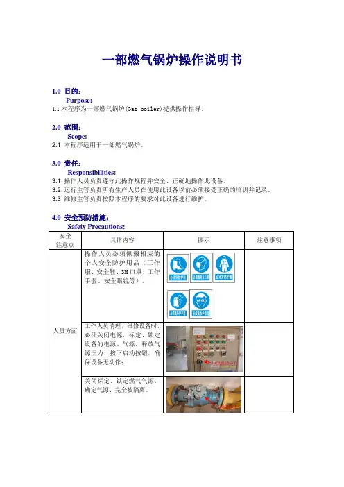
一部燃气锅炉操作说明书1.0 目的:Purpose:1.1本程序为一部燃气锅炉(Gas boiler)提供操作指导。
2.0 范围:Scope:2.1 本程序适用于一部燃气锅炉。
3.0 责任:Responsibilities:3.1 操作人员负责遵守此操作规程并安全、正确地操作此设备。
3.2 运行主管负责所有生产人员在使用此设备以前必须接受正确的培训并记录。
3.3 维修主管负责按照本程序的要求对此设备进行维护。
4.0 安全预防措施:Safety Precautions:安全注意点具体内容图示注意事项人员方面操作人员必须佩戴相应的个人安全防护用品(工作服、安全鞋、3M口罩、工作手套、安全眼镜等)。
工作人员清理,维修设备时,必须关闭电源,标定、锁定设备的电源、气源,释放气源压力,按下启动按钮,确保设备无动作;关闭标定、锁定燃气气源,确定气源、完全被隔离。
气阀锁定孔电隔离锁定孔盲扳完全隔离气源操作人员进行维修、上下楼梯等登高作业,人员上下时应拉扶手,注意脚下阶梯,防止发生踏空、滑倒、跌倒、绊倒和坠落等意外情况。
操作人员清理维修内部受限空间时,必须关闭及锁定和标定设备电源,并在仓外部放置一个清理标示牌。
人源进入前,必修开仓通风,降温处理,必须有人看护方可进行。
维修,清理水箱时,必须排清水箱,运用安全电源照明,确保通风良好,有人看护方可进行。
5.1 锁定/标定:锁定标定是在设备需要调整或维护操作过程时保障人员安全的程序。
在设备需要进行维护等操作时,锁定标定时通过切断主电路和使用锁定标牌确保设备锁定。
每把锁只可以有一把钥匙,并且钥匙必须保存在正在操作设备的操作人员手中,以避免一名员工在作业时另一员工打开电源而发生意外事故。
设备/工具Equipment规格Specification数量Quantity设备参数Equipment parameters燃油(气)蒸汽锅炉WNS4-1.25-Y(Q) 1 额定蒸发量 4 T/h 额定蒸汽压力 1.25 Mpa 额定蒸汽温度194 ℃给水泵JGGC4.8-143 2 电机功率 4 KW 流量 4.8 m³/h 转速2900 r/min7.0 操作步骤控制按纽等电气元件是否正常。
SZS17.5-1.6/150/90-Q双锅筒水管燃气热水锅炉产品安装使用说明书目录第一部分锅炉规范及简介-----------------------------------------------------(2)-(3)(一)锅炉规范及结构简介------------------------(2)-(3)(二)锅炉出厂配置------------------------------(3)第二部分安装说明-------------------------------------------------------------(4)-(5)(三)安装前的准备工作--------------------------(4)(四)锅炉本体的安装----------------------------(4)(五)防爆门的安装------------------------------(4)(六)燃烧器的安装------------------------------(4)(七)平台扶梯的安装----------------------------(4)(八)省煤器的安装------------------------------(4)(九)管道、阀门仪表及附件的安装----------------(4)-(5)(十)烟道的安装------------------------------- (5)(十一)电器控制箱的安装-------------------------(5)(十二)引风机的安装-----------------------------(5)(十三)水压试验---------------------------------(5)第三部分使用说明-------------------------------------------------------------(6)-(11)(十四)烘炉--------------------------------------(6)(十五)煮炉-------------------------------------(6)-(7)(十六)升火-------------------------------------(7)(十七)密封试验---------------------------------(7)-(8)(十八)供(暖)水-------------------------------------(8)(十九)正常运行---------------------------------(8)-(9)(二十)停炉-------------------------------------(9)(二十一)锅炉维护保养-----------------------------(10)(二十二)受压元件的检验和水压试验-----------------(10)-(11)(二十三)说明-------------------------------------(11)本产品锅炉执行标准《工业锅炉通用技术文件》J B/T10094-2002SZS10-1.25-YQ双锅筒水管燃油汽锅炉产品安装使用说明书第一部分锅炉规范及简介1.锅炉规范及结构简介1.1 SZS17.5-1.6/150/90-Y(Q)双锅筒水管燃气锅炉主要规范该锅炉为双锅筒纵向布置水管燃气热水锅炉,散装出厂,现场组装后需安装管道、阀门、仪表、平台扶梯、省煤器、烟道及各项辅机。
1Dear CustomerYour Syntesi boiler has been designed to meet and exceed the very latest standards in gas central heating technology and if cared for, will give years of reliable use and efficiency. Please therefore take some time to read these instruc-tions carefully.Do’s and Don’tsq Do ensure that the system pressure is periodically checkedq Do ensure that you know how to isolate the appliance in an emergency q Do ensure that you are familiar with the appliance controlsq Do ensure that your installer has completed the appliance log book q Do not attempt to remove the appliance casing or gain internal access q Do not hang clothes etc. over the applianceq Do not forget to have the appliance serviced annuallyq Do ensure that your installer or engineer uses only genuine Vokera spare parts21.Pressure gauge2.Clock aperture3.N/A4.Hot Water temperature selector5.Mode selector switch6.Status LED7.Digital display8.Heating temperature selector9.DHW request LEDFig. 1Fig. 2Filling valveFilling LoopIsolating valve45786123931.1GAS APPLIANCESGas Safety (Installations and Use) Regulations.In the interests of your safety and that of others it is a legal requirement that all gas appliances are installed and correctly maintained by a compe-tent person and in accordance with the latest regu-lations.1.2ELECTRICAL SUPPLYPlease ensure that this appliance has been prop-erly connected to the electrical supply by means of a double pole isolator or un-switched socket,and that the correct size of fuse (3 amp) has been fitted.WARNING:THIS APPLIANCE MUST BE EARTHED!1.3GUARANTEE REGISTRATION CARDPlease take the time to fill out your guarantee registration card. The completed warranty card should be posted within 30 days of installation.1.4BENCHMARK LOG BOOKThe Benchmark Log Book is supplied with your boiler. This important document must be completed during the installation/commissioning of your boiler.All CORGI Registered Installers carry a CORGI ID card and have a registration number. Both shoulf be recorded in your Benchmark Log Book. You can check your installer by calling CORGI direct on 01256 372300. Failure to install and commission the appliance in accordance with the manufacturers instructions may invalidate the warranty. This does not affect your statutory rights.1.5HOW DOES IT WORK?Your Syntesi boiler is a combined central heating and hot water boiler. The Syntesi supplies heated water to your radiators and provides hot water when a hot water outlet is opened.Your Syntesi boiler can be controlled by several different types of controls such as:q Integral time clock q External time clock q Vokera remote-controlq Programmable room thermostatIt’s therefore necessary to ensure that these in-structions are read in conjunction with the instruc-tions supplied with the relevant control.The Syntesi lights electronically and does not have a pilot light.In the unlikely event of a fault developing with your boiler, the supply of gas to the burner will be terminated automatically.1.6ADDITIONAL FEATURESYour Syntesi boiler includes some of the latest features that have been designed to ensure con-tinued safety and reliability of the appliance.These include:q appliance frost protection q hot water pre-heatq pump, valve actuator & fan anti-block1.7DIMENSIONSHEIGHT 820mmWIDTH 400-500mm depending on model DEPTH355mm1.8CLEARANCES REQUIREDABOVE 150mm BELOW 150mm SIDES 12mm FRONT600mmqdiagnostic fault codes q LED status indicator q digital displayFROST PROTECTIONYour Syntesi boiler will automatically operate to minimise the risk of frost damage to the boiler itself. The frost protection device will be disabled should the power supply to the boiler be dis-rupted.HOT WATER PRE-HEATThe Syntesi’s pre-heat facility ensures that the boiler responds quickly to any hot water requests.PUMP , ACTUATOR, & FAN ANTI-BLOCKWhen the boiler has not been used for more than 24 hours, the pump, fan & valve actuator, are en-ergised for a few seconds to ensure that they does not stick or jam. This function will be disabled should the power supply to the boiler be dis-rupted.DIAGNOSTIC FAULT CODESIn the unlikely event of a fault developing, the boiler displays a unique fault code that helps iden-tify where the fault lies.LED STATUS INDICATORThe Syntesi is equipped with an LED status indi-cator that gives a visual indication of whether the boiler is working normally or has developed a fault.DIGITAL DISPLAYThe digital display shows the current tempera-ture of the hot water or heating outlet (depend-ing on mode of operation). In addition, it also dis-plays a unique fault code in the unlikely event of the boiler malfunctioning.THINGS YOU SHOULD KNOW42.1BEFORE SWITCHING ONBefore switching the appliance on please famil-iarise yourself with:q how to isolate the appliance from the gas, water and electricity suppliesq how to check and top-up – if necessary – the system water pressureq the time clock or boiler controlq any external thermostats and their functions q the appliance controls.2.2APPLIANCE CONTROLS (see fig. 1)The appliance controls are concealed behind the front flap. To gain access to the controls simply press the top centre of the flap, release and pull downwards.The appliance has a mode selector switch, vari-able thermostats for controlling the temperature of the heating flow outlet and the hot water outlet,system pressure gauge and an aperture for an integral clock. The mode selector switch has three positions:q hot water only q offq heating & hot waterThe variable hot water thermostat allows you to set the temperature of the water to your hot wa-ter taps between 37.5°C (min) and 65°C (max).The appliance will have been commissioned by your installer to deliver hot water at both a rea-sonable temperature and flow rate.Should you wish to increase the temperature of the hot water and the hot water thermostat is al-ready set at maximum, simply reduce the flow of water as it comes out of the tap. Please consult your installer for further advice if required.The variable heating thermostat allows you to set the temperature of the water to your radiators be-tween 40°C (min) and 80°C (max).The pressure gauge shows the current pressure of the system, the gauge should be set between 1 and 1.5 bar. When the appliance is operating the gauge may rise or fall slightly, this is quitenormal. The minimum permissible level for the safe and efficient operation of the appliance is 0.5 bar. Should the pressure fall below 0.5 bar,the boiler shuts off automatically.Depending on the type of controls specified by your installer you may have an integral Vokera time clock or the Vokera remote control fitted, if so, supplementary instructions can be found at the back of this booklet. If an external time clock has been fitted, please refer to the instructions supplied with such.2.3LIGHTING THE BOILEREnsure the gas and electrical supplies to the boiler are turned on.Turn the mode switch to the ‘heating & hot water’position. The status indicator should be ‘Green’ if the status indicator is flashing ‘Red’ refer to 3.2.Refer to the particular instructions for the type of time clock or control fitted and ensure there is a demand for heating. If there is a room thermostat you should ensure that this is also calling for heat.When there is a demand for heating via the above controls the boiler will go through an ignition se-quence, whereby the burner will light.If the appliance fails to ignite during the ignition sequence, allow a period of two minutes before re-setting.To adjust the output temperature of the appliance turn the thermostat knob clockwise to increase or anti-clockwise to decrease.When the appliance reaches the set tempera-ture, the burner will go off for minimum period of approximately 3 minutes.When the time clock or external thermostats heat-ing request has been satisfied, the appliance will switch off automatically.When the mode selector switch is in the hot wa-ter only or heating & hot water position, the boiler will light to supply hot water whenever a hot wa-ter outlet (tap) is opened.Periodically the appliance will light on minimum output as a function of the pre-heat facility.Fig. 3Normal Operating PositionFilling PositionClosed Position1.9FILLING VALVEThe filling valve is located underneath the boiler.The filling valve lever has 3 positions:q normal operating position q closed position q filling position.The valve lever should never be turned to the fill-ing position unless the filling loop has been con-nected and the system pressure requires topping-up (see 3.1).GETTING STARTED53.1HOW TO TOP-UP THE SYSTEM PRESSURE (fig. 2)The system pressure must be checked periodi-cally to ensure the correct operation of the boiler.The needle on the gauge should be reading be-tween 1 and 1.5 bar when the boiler is in an off position and has cooled to room temperature. If the pressure requires ‘topping-up’ use the follow-ing instructions as a guide.q Locate the filling valve connections (below the boiler).q Attach the filling loop to both connections.q Open the isolating valve (Left) slowly.q Move the filling valve (Right) slowly to the fill position (fig. 3) until you hear water entering the system.q Move the filling valve back to its normal posi-tion (fig. 3) when the pressure gauge (on the boiler) reads between 1 and 1.5 bar.q Close the isolating valveq Remove the filling loop from the connections.3.2HOW TO RESET THE APPLIANCEWhen the LED status indicator is flashing red,the appliance will require to be reset ing the mode selector switch, turn it to the OFF/RESET position, then turn it back to the ‘hot wa-ter only’ or ‘heating & hot water’ position (see also 3.3).Allow a period of two minutes to elapse before turning the mode switch to the reset position.IMPORTANTIf the appliance requires to be reset frequently, it may be indicative of a fault, please contact your installer or Vokera Customer Services for further advice.3.3DIAGNOSTIC FAULT CODESDisplay showsAction required01Burner has failed to ignite.Ensure gas meter is turned on.Wait two minutes before resetting. If problem persists call engineer.02Boiler has over-heated, wait 5 minutes. for boiler to cool. Reset boiler.If problem persists call engineer.03Flue problem.Call engineer.04Low water pressure. Ensure pressure gauge is above 0.5 bar (see 3.1).Reset boiler.05Communication fault (RC05 only).Call engineer.06Boiler fault.Call engineer.07Boiler fault.Call engineer.08Burner over-heat.Call engineer.d1 & d2Problem with condense trap/pipe/sensor.Call engineer.3.4HOW TO SHUT DOWN THE SYSTEM FOR SHORT PERIODSThe system and boiler can be shut down for short periods by simply turning the time clock or boiler control to the off position (see the instructions sup-plied). It is also advisable to turn off the main water supply to the house.3.5HOW TO SHUT DOWN THE SYSTEM FOR LONG PERIODSIf the house is to be left unoccupied for any length of time – especially during the winter – the sys-tem should be thoroughly drained of all water.The gas, water, and electricity supply to the house should also be turned off. For more detailed ad-vice contact your installer.3.6HOW TO CARE FOR THE APPLIANCETo clean the outer casing use only a clean damp cloth. Do not use any scourers or abrasive clean-ers.6INTRODUCTIONThe Vokera RC05 remote control is an optional acces-sory that enables the boiler and its functions to be con-trolled from another location from that of the boiler. The RC05 can be used a room thermostat or programmable room thermostat and can also be connected to an out-side temperature sensor.When the RC05 is connected to the boiler the controls on the boiler are over-ridden by the RC05.These instructions should be read in conjunction with the RC05 instructions if your installer has connected an RC05remote control to your boiler.QUICK-REFERENCE GUIDEBoiler switched off – OFF is shown in the display Hot Water only+ or – buttons until the ENTER to store the new setting.4.1WHAT IF I SUSPECT A GAS LEAKIf you suspect a gas leak, turn off the gas supply at the gas meter, and contact your installer or local gas supplier. If you require further advice please contact your nearest Vokera office.4.2WHAT IF I HAVE TO FREQUENTLY TOP-UP THE SYSTEMIf the system regularly requires topping-up, it may be indicative of a leak. Please contact your in-staller and ask him to inspect the system.4.3WHAT IF THE STATUS LED IS FLASHING RED If the red LED is flashing it indicates that the boiler or system has developed a problem, when this happens the boiler automatically shuts down and requires to be reset manually (see 3.2).VOKERA RC05 REMOTE CONTROL4.4WHAT IF THE APPLIANCE IS DUE ITS ANNUAL SERVICEAdvice for tenants onlyYour landlord should arrange for servicing.Advice for homeownersPlease contact Vokera Customer Services (0870333 0220 (UK) or 05655057 (ROI) if you would prefer a Vokera service engineer or agent to serv-ice your appliance. Alternatively your local CORGI registered engineer may be able to service the appliance for you.4.5WHAT IF I NEED TO CALL AN ENGINEER If you think your boiler may have developed a fault please contact your installer or Vokera Cus-tomer Services ************(UK)or05655057(ROI) have all your details to hand including full address and postcode, relevant contact numbers,and your completed appliance log book.Heating & Hot Watersymbols are shown in the display. To adjust the hot water outlet temperature and/or Heating outlet tempera-then press the + or – buttons until the required tem-perature is displayed, press ENTER to store the new set-ting.Adjusting the room temperature setting – with the con-trol set to the Heating & Hot Water mode, press ENTER the currently set room temperature will begin to flash. Use the + or – buttons until the required temperature is dis-played, press ENTER to store the new setting.FAULT CONDITION - the symbol and a fault code will appear in the display. Press RESET to enable the appli-ance to reset itself. Should an alarm code be repeatedly displayed, consult the users guide for specific help. Al-ways allow at least 2-minutes before resetting the ap-pliance.7Regulates the heating and domestic hot water temperatureMakes a temporary change in levelPrograms the boilerChanges mode (OFF-SUMMER-WINTER)Sets cleaning and holiday functionIncreases settingSelects and confirms data and changes room temperatureDecreases settingReleases boiler, reset data and tests displayDESCRIPTION OF CONTROL PANELDESCRIPTION OF BUTTONS8DESCRIPTION OF DISPLAY1-Boiler lockout indicator 2-Heat request indicator 3-Heating indicator4-Domestic hot water indicator 5-Economy level temperature indicator 6-Comfort level temperature indicator 7-Scheduled servicing indicator 8 -Room thermostat indicator 9 -Timer thermostat indicator10 -Boiler control indicator11Underfloor heating function indicator 12 -Thermoregulation status indicator 13 -Cleaning/holiday function indicator 14 -T elephone interface function indicator15 -Time and error numeric display field 16 -Temperature numeric display field 17 -Daily schedule progress bar 18 -Week day display segments 19 -EXT, outdoor temperature95.1SETTING THE MECHANICAL CLOCKThe Vokera mechanical time clock can automati-cally switch your boiler on and off at the same time every day of the week. The minimum ’on’ or ‘off’ period can be as little as 15 minutes.The outer clock face consists of 96 black pins.Each pin represents a time period of fifteen min-utes. When a pin is pushed towards the outside of the clock face, the time clock is in an ‘on’ posi-tion, consequently when it is pushed towards the inner part of the clock face it is in an ‘off’ position.5.1.1SETTING THE ‘ON ’ & ‘OFF ’ TIMESPush the necessary amount of pins towards the outer clock face for the time period that you want the boiler to be ‘on’ (for example if you wanted the boiler to be on between 4.00PM and 8.00PM,push out the 16 pins located between 16 and 20on the clock face).5.1.2SETTING THE ‘TIME OF DAY ’Grasp the outer clock face and turn clock-wise until the correct ‘time of day’ is opposite the black pointer.5.1.3SELECTOR SWITCHThe time clock has a three-position switch. This switch over-rides the timed settings (‘on’ & ‘off’times) of the clock. 5.2SETTING THE DIGITAL CLOCKThe Vokera digital time clock will automatically switch your boiler on and off. It has a total of twenty different switching commands, consisting of ten ‘on’ commands and ten ‘off’ commands.Each ‘on’ or ‘off’ command can be used to switch the boiler ‘on’ or ‘off’ at the same time:q every day of the week q monday to Saturday q monday to Friday VOKERA TIME CLOCKExample Group of days On OffCommands used Mon. to Fri.06.0009.002Mon. to Fri.16.0021.002Sat. & Sun.08.3010.302Sat. & Sun.17.0023.002T otal8 used Commands ‘free’12 unusedVokera 24 Hour Mechanical Clock5.2.1BEFORE PROGRAMMINGGently press and release the ‘Res.’ button with a pencil or similar, this will clear the memory of all information. This should only be done when you want to change or insert a complete new pro-gramme.5.2.2SETTING THE TIME OF DAYThe ‘real time’ clock has to be set to the actual day of the week and time of day, to do this:q press and hold the q press the ‘Day’ button until the actual day shows in the display (1= Monday, 2= Tuesday, 3=Wednesday, etc.)q if setting the clock during ‘British summertime’press the ‘+/-1h’ button once (use a pencil or Fig. 2Fig. 3Day buttonVokera Digital Time Clock105.2.3q Repeatedly press the Prog. Button until the —:— symbol appears in the clock display (see fig. 4).q Press the Day button until the desired group of days or desired day is shown.q Press the ‘h’ button until the desired hour for switching the boiler on is shown.q Press the ‘m’ button until the desired minutes are shown.qshown (see fig. 5).q Press the button.Fig. 4Fig. 55.2.4ENTERING (off) COMMANDSq Repeatedly press the Prog. Button until the —:— symbol appears in the clock display (fig. 4).q Press the Day button until the desired group of days or desired day is shown.q Press the ‘h’ button until the desired hour for switching the boiler off is shown.q Press the ‘m’ button until the desired minutes are shown.q Press the Select button until the symbol is shown (see fig. 6).q Press the Once the programming has been completed you will havethat particular time.5.2.5ADVANCING OR LOCKING PROGRAMME COM-MANDSBy pressing the Select button you can advance the time clock to the next command setting (from ‘on’ to ‘off’ or ‘off’ to ‘on’) or lock the time clock to a particular command (‘on’ continuously or ‘off’continuously).qq - OFF qq[NOTEThe actual time can be changed to account for British summertime by simply pressing then re-leasing the +/- 1h button.Fig. 6HELPFUL HINTSq You can check and/or alter the programme set-tings at any time by pressing the Prog button.q The number of unused ‘commands’ can be checked by pressing the Prog button until FR is displayed alongside the number of unused commands.q In the event of a power failure, the clock has a battery back-up. The programme will be held in the memory for approximately 2 weeks.Charging time is 70 hours.q Take a note of the settings you have pro-grammed, as local power surges can some-times reset the memory of the clock.2.dE-3/5-15421.doCenergizing home heatingVokèra Ltd.4th Floor, Catherine House, Boundary Way, Hemel Hempstead, Herts, HP2 7RPEmail:*******************.ukWeb:Sales, Technical Advice, General Enquiries - Tel: 0870 333 0520 Fax: 01442 281403AfterSalesService-Tel************Vokèra IrelandWest Court, Callan, Co KilkennyTel: 05677 55057 Fax: 05677 55060Vokèra Ltd. reserve the right to change the specifications without prior notice. Consumers’ statutory rights are not affected.A Riello Group CompanyCOLLECTIVE MARK“Vokèra”supports Benchmark。
燃气锅炉使用说明书燃气锅炉使用说明书---1. 产品概述燃气锅炉是一种利用燃气燃烧产生热能的设备,广泛应用于家庭供暖、热水供应等领域。
本使用说明书主要介绍了燃气锅炉的安装、操作、维护等方面的内容,以帮助用户正确使用燃气锅炉,提高使用效果。
2. 安装要求在安装燃气锅炉之前,请确保满足以下要求:- 安装位置应远离易燃易爆材料,并确保有足够的通风空间;- 安装位置应水平,并能承受燃气锅炉的重量;- 安装位置应充分考虑排放烟气的问题,确保烟气畅通,不会对周围环境造成污染;- 安装时应保证燃气管道与锅炉的连接紧固可靠,不会出现泄漏;- 安装时应按照相关法律法规进行,确保符合安全标准。
3. 操作说明3.1 准备工作在正常操作燃气锅炉之前,请进行以下准备工作:- 确保燃气供应正常,并检查燃气阀门是否打开;- 检查水压是否在正常范围内,必要时进行补充;- 清理锅炉内部的灰尘和杂物,确保不会影响燃烧效果。
3.2 启动和关闭锅炉- 启动锅炉时,先打开燃气阀门,并调节适当的燃气量和燃气压力;- 打开电源开关,并按下启动按钮,等待锅炉启动;- 启动后,可根据需要调节温度和运行时间;- 关闭锅炉时,先关闭燃气阀门,并将温度设为最低,然后按下停止按钮,待锅炉停止运行后,再关闭电源开关。
3.3 注意事项- 使用锅炉时,请遵循相关安全操作规范;- 请勿随意更改锅炉的参数设置,以免影响正常运行;- 锅炉使用过程中如发现异常情况,请立即停止使用,并联系售后服务;- 定期检查锅炉的燃气管道、水管等连接部分,确保安全可靠。
4. 维护保养4.1 清洁和保养定期对燃气锅炉进行清洁和保养,可以延长使用寿命,提高效果:- 清洁锅炉表面的污垢和灰尘,保持外观干净;- 清洗锅炉内部的热交换器,以保证热能传递效率;- 检查燃气管道和水管的连接情况,确保无泄露;- 定期检查燃气阀门、电源开关等机械部件的工作状态。
4.2 故障处理在使用燃气锅炉过程中,可能会遇到一些故障情况,如无法启动、温度异常、水压过高等。
山东(威玛)家用燃气锅炉热水器说明书山东(威玛)家用燃气锅炉热水器说明书尊敬的用户:感谢您选择山东(威玛)家用燃气锅炉热水器。
为了确保您的安全和正常使用,我们特别为您提供以下使用说明,请仔细阅读并按照指示操作。
1. 安全注意事项:\n - 请确保安装位置通风良好,远离易燃物品和儿童。
\n - 请勿将电源线与水管接触,以免发生电击事故。
\n - 在使用过程中,请勿将手伸入水箱内部。
\n - 如发现异常情况(如漏电、异味等),请立即停止使用并联系售后服务。
2. 安装步骤:\n - 请将产品放置在平稳的地面上,并确保底部有足够的空间供通风。
\n - 将水管连接到进水口和出水口,并确保连接牢固。
\n - 将天然气管道连接到燃气进口,并检查连接是否牢固。
3. 使用方法:\n - 打开天然气阀门,并按下点火按钮启动点火程序。
在点火过程中,请注意安全,避免触碰火焰。
\n - 调节温度控制器,选择所需的热水温度。
\n - 当需要热水时,打开热水龙头,并等待片刻,直到热水流出。
\n - 使用完毕后,请关闭热水龙头,并关闭天然气阀门。
4. 清洁与维护:\n - 定期清洁燃气锅炉的外部表面,并确保通风口畅通。
\n - 如发现水垢堆积,请使用专用清洁剂进行清洗。
\n -定期检查天然气管道和水管连接是否有松动或泄漏现象。
5. 故障排除:\n - 如发生故障,请先检查电源和天然气供应是否正常。
\n - 如无法解决问题,请联系售后服务,并提供详细的故障描述。
请注意:本说明书仅适用于山东(威玛)家用燃气锅炉热水器。
如需更多信息或有其他问题,请咨询售后服务。
再次感谢您选择山东(威玛)家用燃气锅炉热水器。
我们将竭诚为您提供优质的产品和服务。
祝您使用愉快!山东(威玛)家用燃气锅炉热水器制造商。
CN供用户使用使用手册atmoCRAFT落地式燃气锅炉 VK 654/9VK 754/9VK 854/9落地炉特性应用威能atmoCRAFT 系列落地式燃气锅炉(以下简称“落地炉”)可用作热源为民用和商用建筑供热。
即可直接用于新建供热系统,也可用于对既有供热系统的更新和改造。
可配合威能储水罐为用户提供生活热水。
同时,可选配威能控制器对供热系统进行调节,提高采暖及生活热水的舒适度。
落地炉说明- atmoCRAFT 系列落地炉配有一个可调节燃烧火焰大小的两段火式燃烧器,可以降低燃烧器启停频率并保证落地炉高效率运行。
- 本落地炉配有数字信息显示与故障分析系统(DIA ),便于信息查询、故障排除、系统维护和设备维修。
- 液晶屏可以显示落地炉运行工况。
当系统出现故障时,液晶屏所示的诊断信息和故障代码可以帮助您迅速查找故障原因和解决问题。
目录落地炉特性目录落地炉特性 ...............................................................................21 阅读提示 ........................................................................31.1 文件保管.............................................................................31.2 使用符号.............................................................................31.3CE 标识 (3)1.4 铭牌 .....................................................................................32 安全须知 ........................................................................33 安装与操作指示 ...........................................................43.1威能保证 (4)3.2 正确使用 ............................................................................43.3 安装地点的要求 ...............................................................43.4 清洁落地炉 ........................................................................53.5回收和处理 ........................................................................53.5.1 设备 .....................................................................................53.5.2 包装 .....................................................................................53.6 节能提示.............................................................................54 操作 ................................................................................64.1操控部件 (6)4.2 运用调试前的准备 ...........................................................74.2.1 打开燃气截止阀 ................................................................74.2.2 检查系统压力 ....................................................................74.3 启动 .....................................................................................84.4 生活热水制备 ....................................................................84.4.1 取用生活热水 ..................................................................94.4.2 关闭储水罐.........................................................................94.5 供暖模式运行 ...................................................................94.5.1 系统供水温度设置(连接控制器时)...........................94.5.2 系统供水温度设置(未连接控制器时).......................94.5.3 夏季模式 .............................................................................104.6 设置温控器或恒温阀 ........................................................104.7 信息显示.............................................................................104.8 故障排除.............................................................................114.8.1 供暖运行期间的故障 ........................................................114.8.2 系统缺水引起的故障 ........................................................114.8.3 点火故障.............................................................................124.8.4 落地炉因过热关闭 ............................................................124.8.5 排烟故障.............................................................................124.8.6 供热系统注水 ....................................................................134.9 关闭落地炉.........................................................................134.10 防冻保护.............................................................................144.10.1 防冻保护功能 ....................................................................144.10.2 通过泄水防冻 ....................................................................144.11 保养和维护 ........................................................................144.11.1 检查和维护.........................................................................144.11.2 维护提示.............................................................................144.11.3 烟道测试.. (14)阅读提示 1 安全须知 22安全须知紧急处理危险!闻到燃气气味!可能造成中毒或爆炸的危险!闻到燃气气味时,请执行以下操作: - 打开门窗通风,迅速撤离!- 避免明火,不要吸烟,不要使用打火机!- 不要使用电开关、插销、电铃、电话和建筑中的其它通讯设备!- 关闭落地炉上的燃气阀门以及燃气管道的主阀门!- 通知家人及邻居!- 到达安全地点后及时通知燃气公司!安全指南请始终遵守如下的安全指示。