东芝(TOSHIBA)变频器说明书VF-AS1中文.PDF
- 格式:doc
- 大小:296.00 KB
- 文档页数:7

东芝VF-S11新款通用型变频器1、高扭力从低速起动瞬间,初始转矩输出可达到额定值的二倍。
1Hz-200%。
通过东芝特有的矢量技术,无论是驱起区域(马达加速时),还是再生区域(马达减速时),都能保持平稳地运行。
只要设定一个对数,就可用自动调节来实现力矩自动补尝功能。
带有自动节能模式,使VF-S11变频器的效率达到更高水准。
2、内置EMI噪音滤波器照顾周围环境是VF-S11变频器的又一优点。
单相级别和500伏三相级别的VF-S11变频器带有高衰减性能的EMI滤波器,能大大减弱由变频器产生的RFI噪音或干扰电流。
3、可调换的控制端子线路板在同级变频器中,首创可调换的控制端子线路板。
使接线和维修更加方便。
换下标准的控制端子线路板后,可留出空间在变频器内部装上带有通讯接口的控制端子板(选购件)4、维修保养容易,使用寿命延长VF-S11拥有预警功能。
当电解电容器,冷却风扇及控制线路板的实际使用时间达到更换期限时,操作面板会显示警告信号,提醒使用者及时更换或准备更换。
这是一个非常有用的功能,可作为维修保养的指引。
VF-S11的冷却风扇附有自动开关的功能,使其使用寿命进一步延长。
而且其装卸非常容易,便于更换。
电容器方面,VF-S11的主电路电容器采用寿命延长达10年的电容器,一定程度上延长了变频器的寿命。
VF-S11适应的环境温度最高可达摄氏60度。
5、宽广的功率范围VF-S11作为小型变频器级别,达到15千瓦功率的宽广范围。
序号型 号额定输入电压(V)适配电机功率(KW)1VFS11-4007PL三相380VAC0.75KW2VFS11-4015PL三相380VAC 1.5KW3VFS11-4022PL三相380VAC 2.2KW4VFS11-4037PL三相380VAC 3.7KW5VFS11-4055PL三相380VAC 5.5KW6VFS11-4075PL三相380VAC7.5KW7VFS11-4110PL三相380VAC11KW8VFS11-4150PL三相380VAC15KW1VFS11-2004PM三相220VAC0.4KW2VFS11-2007PM三相220VAC0.75KW3VFS11-2015PM三相220VAC 1.5KW4VFS11-2022PM三相220VAC 2.2KW5VFS11-2037PM三相220VAC 3.7KW6VFS11-2055PM三相220VAC 5.5KW7VFS11-2075PM三相220VAC7.5KW8VFS11-2110PM三相220VAC11KW9VFS11-2150PM三相220VAC15KW1VFS11S-2002PL单相220VAC0.2KW2VFS11S-2004PL单相220VAC0.4KW3VFS11S-2007PL单相220VAC0.75KW4VFS11S-2015PL单相220VAC 1.5KW5VFS11S-2022PL单相220VAC 2.2KWVF-nC1小型变频器优异的低速高转矩性能-低速时也可迅速达到200%以上的起动转矩-自动转矩提升、自动在线功能等设置一“触”而就-节能模式再次升级,其节能效果之优引领世界新潮流内置滤波器-滤波器可大大降低因变频器而产生的电磁干扰波,其环保意识也可见一斑-更自如对应世界各国的电气规格-单相220V/三相400V:内置高减衰型EMI滤波器,符合欧洲EMC规格-三项220V:内置标准滤波器,符合日本国土交通省的有关规定,体形更趋精巧-以节省空间见长的小巧体形再一次大大缩小-在多台并列安装时,也可实现无空间密集安装-体积小巧但功能却惊人之多,实用性引领世界潮流首创可拆卸式端子台-首次实现了控制端子台可拆卸化,使布线作业以及维修保养更简便易行-端子台基板与通讯功能基板互换,即可实现通讯功能选件内置化维修保养更为简便-显示易损件报警信号,便于及时维修保养-冷却风扇装卸简便,并有自动ON/OFF开关,大大延长了使用寿命-主回路电容的设计使用寿命可达10年之久-在环境温度600C时也能照常使用,其耐环境性为世界之最(但需降低电流)序号型 号额定输入电压(V)适配电机功率(KW)1VFNC1S-2002P单相220VAC0.2KW2VFNC1S-2004P单相220VAC0.4KW3VFNC1S-2007P单相220VAC0.75KW4VFNC1S-2015P单相220VAC 1.5KW5VFNC1S-2022P单相220VAC 2.2KW西米克工业传动设备有限公司SMK Industrial Transmission Co., Ltd. 地址:广东省东莞市长安镇上沙管理区 电话:(86) 769-8532 5010传真:(86) 769-8532 5070邮箱:****************网址:。
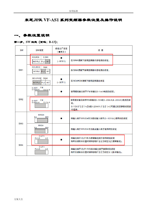
东芝川仪VF-AS1系列变频器参数设置及操作说明
一、参数设置说明
第一步、SW设定(页码:B-13):
第二步、设置基本频率电压(页码:E-16):第三步、最高频率设定(页码:E-17):
第四步、上限、下限频率设定(页码:E-17):
第五步、通过面板EASY键进行远程/就地切换(页码:E-45):
第六步、通过模拟输入信号(4-2mA,VⅠ/Ⅱ端子)设定(页码:G-12):
第七步、通过FM端子反馈速度信号(4~20mA输出)的设定(页码:E-28、29):
第八步、通过AM端子反馈电流信号(4~20mA输出)的设定(页码:E-29、30):
第九步、DO输出端子功能的设定:
首先确定SINK逻辑的接线方式,如下图(页码:B-14):
设置输出端子功能(页码:G-5、6、7、8)
第十步、DI输入端子功能的设定(页码:G-2、3、4):
第十一步、电机常数设置(页码:F-36):关于面板输入正反转的设置(页码:E-21):
二、操作说明
变频器操作分为二种操作方式:远程(DCS)、就地(面板)
远程/就地切换方式:通过按下面板EASY键,有三个指示灯同时亮,表示为面板控制方式
技术咨询:
:-67300121 -67300119
传真:-67300126
川仪工程技术
2010年10月25日。

东芝(TOSHIBA)变频器VF-S9说明书东芝(TOSHIBA)变频器VF-S9说明书1、概述1.1 产品介绍1.1.1 变频器VF-S9的功能与特点1.1.2 应用领域1.2 术语和定义1.2.1 常见术语解释1.2.2 缩写定义2、安全说明2.1 安全警示2.1.1 标志和符号的意义2.1.2 安全注意事项2.2 安装要求2.2.1 电气安装要求2.2.2 机械安装要求2.3 使用前的检查和测试2.3.1 检查包装箱2.3.2 电气连接前的检查2.4 启动与操作2.4.1 启动前的准备工作2.4.2 启动与停止操作2.5 停机与维护2.5.1 停机前的准备工作2.5.2 维护事项与周期3、硬件说明3.1 外观与接口3.1.1 变频器的输入与输出接口 3.1.2 控制面板及指示灯3.2 参数设定和调整3.2.1 基本参数设定3.2.2 高级参数设定3.3 输入与输出信号3.3.1 输入信号的设置与定义3.3.2 输出信号的设置与定义4、程序控制与编程4.1 控制方式选择4.1.1 闭环控制4.1.2 开环控制4.2 控制参数设定4.2.1 速度控制参数设定4.2.2 转矩控制参数设定4.3 外部通信接口4.3.1 RS485通信接口4.3.2 Modbus通信协议5、故障诊断与排除5.1 常见故障代码及解决方案5.2 故障现象与处理6、附录6.1 技术参数6.1.1 输入电源要求6.1.2 输出电流与功率6.2 电气连接图6.3 外部设备接口6.4 规格表本文档涉及附件:1、电气连接图2、规格表本文所涉及的法律名词及注释:1、著作权:对创作的文字、美术、摄影、音乐、电影等作品享有财产权利和非财产权利的法律保护。
2、商标:对商品或服务的标识、商号、商业标志等享有独占性权利的法律保护。
E6581315⑤TOSVERT VF-AS1 SeriesRS485 Communication FunctionInstruction Manual* The contents of this manual are subject to change without notice.Read firstSafety precautionsThis manual and labels on the inverter provide very important information that you should bear in mind to use the inverter properly and safely, and also to avoid injury to yourself and other people and damage to property.Read the safety precautions in the instruction manual for your inverter before reading this manual and strictly follow the safety instructions given.NoticeReference♦ Insert an electromagnetic contactor between the inverter and the power supply so that the machine can be stopped without fail from an external controller in case of an emer-gency.♦ Do not write the same parameter to the EEPROM more than 10,000 times. The life time of EEPROM is approximately 10,000 times.(Some parameters are not limited, please refer to the “9.Parameter data “)When using the TOSHIBA inverter protocol and the data does not need to be records, use P command (the data is written only to RAM).♦ About the handling of the inverter, please follow the instruction manual of the inverter.Inverter instruction manualSection 4.2“Commands”Contents1.General outlines of the communication function (3)2.Data transmission specifications (4)munication protocol (5)3.1.About the handling of received frames (5)4.TOSHIBA Inverter Protocol (6)4.1.Data transmission format (7)4.1.1.Data transmission format used in ASCII mode (7)4.1.2.Data transmission format used in binary mode (10)4.1.3.Transmission format of Block Communication (13)mands (17)4.3.Transmission errors (20)4.4.Broadcast communication function (21)4.5.Examples of the use of communication commands (23)4.6.Examples of Communication programs (24)5.MODBUS-RTU protocol (29)5.1.MODBUS-RTU transmission format (30)5.1.1.Read command (03) (30)5.1.2.Write command (06) (31)5.2.CRC Generation (32)5.3.Error codes (32)6.Inter-drive communication (33)6.1.Proportional control of speed (37)6.2.Transmission format for inter-drive communication (38)munication parameters (40)7.1.Baud rate(H , H ) , Parity (H ) (42)7.2.Inverter number(H ) (42)munication time-out detection (f803) (f804) (f808) (43)7.4.Send waiting time (H , H ) (45)7.5.Free notes(H ) (45)mands and monitoring from the computer (46)munication commands (commands from the computer) (46)8.2.Monitoring from the computer (51)8.3.Utilizing panel (LEDs and keys) by communication (60)8.3.1.LED setting by communication (60)8.3.2.Key utilization by communication (63)9.Parameter data (64)Appendix 1 Table of data codes (69)Appendix 2 Response time (70)Appendix 3 Compatibility with the communication function of the VF-A7 (71)Appendix 4 Troubleshooting (72)Appendix 5 Connecting for RS485 communication (73)1. General outlines of the communication functionThis manual explains the RS485 communication function provided for the TOSVERT VF-AS1 series of industrial inverters.(1) RS485 communication by the use of a two-wire RS485 communication port (standard function) (2) RS485 communication by the use of a four-wire RS485 communication port (standard function)By using these communication functions in combination with the computer link function designed to establish a link between a higher level computing machine or controller (hereinafter referred to as a computer) and each inverter on the network, or with the inter-drive communication function that al-lows proportional control of inverters without using a computer, you can set up a network for data communication between inverters.There are two communication protocols available: Toshiba Inverter Protocol and MODBUS-RTU Protocol (this command does not support all commands). To select a protocol, the communication protocol selection parameter f807 or f829 is used. (Refer to Section 3. Communication pro-tocol.)<Computer link>By preparing the program (explained later), the following information can be exchanged between the computer (host) and the inverter.(1) Monitoring function (used to monitor the operating status of the inverter: Output frequency,current, voltage, etc.)(2) Command function (used to issue run, stop and other commands to the inverter) (3) Parameter function (used to set parameters and read their settings)<Inter-drive communication function>Master inverter sends the data, that is selected by the parameter, to all the slave inverters on the same network. This function allows a network construction in which a simple synchronous or propor-tional operation is possible among plural inverters (without the host computer).As for data communication codes, the TOSVERT VF-AS1 series of inverters support the binary (HEX) code, in addition to the JIS (ASCII) code. A communication number is used to access the desired data item.* The smallest unit of information that computers handle is called a “bit (binary digit),” which repre-sents the two numbers in the binary system: 1 or 0. A group of 16 bits is referred to as a “word,” which is the basic unit of information the VF-AS1 series of inverters use for data communication. One word can handle data items of 0 to FFFFH in hexadecimal notation (or 0 to 65535 in decimal notation).1 bit(1) 2-wire RS485 communication connector(2) 4wire RS485 communication connector2. Data transmission specifications*1: Changes to setting do not take effect until the inverter is turned back on or reset.*2: JIS-X-0201 (ANSI)-compliant 8-bit codes are used for all messages transmitted in ASCII mode and vertical (even) parity bits specified by JIS-X-5001 are added to them. These even parity bitscan be changed to odd parity bits by changing the parameter setting (a change to the parametersetting does not take effect until the inverter has been reset.)*3: Here are the default character transmission format.Characters received: 11 bits (1 start bit + 8 bits + 1 parity bit + 1 stop bit)STARTBIT BIT0 BIT1 BIT2 BIT3 BIT4 BIT5 BIT6 BIT7 PARITYBITSTOPBITThe inverter receives one stop bit.(The computer can be set so as to send 1, 1.5 or 2 stop bits.) Characters sent: 12 bits (1 start bit + 8 bits + 1 parity bit + 2 stop bits)STARTBIT BIT0 BIT1 BIT2 BIT3 BIT4 BIT5 BIT6 BIT7 PARITYBITSTOPBITSTOPBITThe inverter sends two stop bits.(The computer can be set so as to receive 1, 1.5 or 2 stop bits.)3. Communication protocolThis communication protocol supports the TOSHIBA Inverter Protocol and part of MODBUS-RTU protocol.Select the desired protocol from in the following communication protocol selection parameters (H , H ).“Parameter Name H and H , Communication Number. 0807 and 0829”Data Range: 0, 1 (Initial value: 0)0: TOSHIBA (Includes inter-drive communication) 1: MOUBUS-RTU* A parameter change is reflected when the inverter is reset, such as in power off.3.1. About the handling of received framesTo send and receive data frames, a frame synchronization system for locating the start and end points of each frame is defined with time for which no data is sent (time interval equivalent to the time required to send 3.5 bytes of data).If no data is sent for the time required to send 3.5 bytes of data at the current transmission speed (approx. 4 ms or more at 9,600 bps or approx. 2 ms or more at 19,200/38,400 bps) after receipt of a frame, the entire frame is assumed to have reached and information in it is analyzed. For this rea-son, an interval corresponding to at least 3.5 bytes of data must be placed between frames.When sending a significant data set using two or more frames, an interval corresponding to at least 1.5 bytes of data must be placed between frames. If an interval corresponding to 1.5 bytes or more is not placed, the contents of a frame are analyzed separately from those of the other frames, and therefore communication are not carried out normally.When two or more inverters on the same line are controlled individually one after another, not only data from the host computer to an inverter but also a response from an inverter to the host com-puter are transmitted to the other inverters on the line too. Therefore, an interval corresponding to at least 3.5 bytes should be placed between the time when the host computer receives a response from an inverter and the time when it sends a frame to the next inverter. Otherwise the return frame received and the frame that is sent immediately after receipt of the return frame will be recognized as one frame and communication will not be carried out normally.Frame AFrame B[Correct]1.5 bytes or more Frame A (1/2)[Wrong ] If divided into two smaller frames, frame A cannot be received as asingle frame.Frame A (2/2)3.5 bytes or moreFrame BNote: Correct if the interval correspondsto less than 1.5 bytes of data.Note: An inverter cannot receive frameB before it finishes analyzing the contents of frame A.4. TOSHIBA Inverter ProtocolSelect “TOSHIBA” (H , H = ) in the communication protocol selection parameters.“TOSHIBA” (H , H = ) is set for initial communication protocol selection of shipmentsetting. (See “3. Communication protocol.”)Exchange of data between the computer and the inverterIn communication between the computer and the VF-AS1 (hereinafter referred to as the inverter),the inverter is always placed in wait states and acts as a slave that operates on a request from thecomputer.A discrimination between ASCII mode and binary mode is automatically made with the start code.Start code “CR” (carriage return)ASCII mode “(” RequiredBinary mode “2FH(/) ” Not required(1) If there is no transmission format or the inverter number that matches, an error occurs and noresponse is returned.(2) When an inverter number is added behind the “(” communication will take place only in case ofbroadcast communication or if the number matches up with that assigned to the inverters.(3) When a time-out period is specified with parameter f803 (communication time-out time), atime-out occurs if communication do not terminate normally within the specified time. With pa-rameter f804 (communication time-out action), you can specify what the inverter should do ifa time-out occurs. For details, refer to Section 7.3.(4) On executing the command received, the inverter returns data to the computer. For the re-sponse time, see Appendix 2, “Response time.”NoteCommunication is not possible for about two seconds after the power is supplied to the inverter untilthe initial setting is completed. If the control power is shut down due to an instantaneous voltagedrop, communication is temporarily interrupted.4.1. Data transmission formatNote: The term “trip status” used in this manual includes retry waiting status and trip retention status.4.1.1. Data transmission format used in ASCII modeA communication number is used to specify a data item, all data is written in hexadecimal, andJIS-X-0201 (ASCII (ANSI))-compliant transmission characters are used.Computer → Inverter(28H) 2 bytes 1 byte 4 bytes 0 to 4 bytes(26H)Checksum areaOmissible1. “(“ (1 byte) : Start code in ASCII mode2. INV-NO (2 bytes) : Inverter number (Omissible in one-to-one communication) ... 00 (30H, 30H) to 99 (39H,39h), *(2AH)The command is executed only when the inverter number matches up with that specifiedusing a parameter.(When * is specified in broadcast communication, the inverter number is assumed to matchif all numbers except * match. When * is specified instead of each digit (two-digit number),all inverters connected are assumed to match.)If the inverter number does not match or if the inverter number is of one digit, the data willbe judged invalid and no data will be returned.3. CMD (1 byte) : Command (For details, see the table below.)4. Communication No.(4 bytes): Communication number (See 11, “Parameter data.”)5. Data (0 to 4 bytes) : Write data (valid for the W and P commands only)6. “&” (1 byte) : Checksum discrimination code (omissible. When omitting this code, you also need to omitthe checksum.)7. Sum (2 bytes) : Checksum (omissible)Add the ASCII-coded value of the last two digits (4 bits/digit) of the sum of a series of bits(ASCII codes) from the start code to the checksum discrimination code.Ex.: (R0000&??) CR28H+52H+30H+30H+30H+30H+26H=160HThe last two digits represent the checksum. = 60When omitting the checksum, you also need to omit the checksum discriminationcode.8. “)” (1 byte) : Stop code (omissible)9. CR (1 byte) : Carriage return codeDetails of commands and dataCMD (1 byte) Write data (0 to 4 bytes) Hexadecimal numberR (52H): RAM read commandW (57H): RAM/EEPROM write command P (50H) RAM write command No dataWrite data (0 to FFFF) Write data (0 to FFFF)Inverter → computerAt time of broadcast communication, returning of data is not executed, except for the inverters to bereturned, when the inverter number is not matched, and the inverter number has only one character.This is because there will be a risk of that the returned data may be deformed.Data returned when data is processed normally (ASCII mode)(28H) 2 bytes 1 byte 4 bytes 0 to 4 bytes(26H)Checksum areaOmissible1. “(“ (1 byte) : Start code in ASCII mode2. INV-NO (2 bytes) : Inverter number (omitted if it is not found in the data received) ... 00 (30H, 30H) to 99 (39H,39H)If the inverter number matches up with that specified using a parameter, data will be re-turned to the computer. In broadcast communication, only the destination inverter (with anumber matching up with the smallest effective number) returns data to the computer.In broadcast communication, no data is returned from any inverters except the inverterbearing a number that matches up with the smallest effective number.Ex.: (*2R0000) CR -> (02R00000000) CR)Data is returned from the inverter with the number 2 only, but no data is returned frominverters with the number 12, 22 ....3. CMD (1 byte) : Command ... The command is also used for a check when an inverter is tripped.Under normal conditions... The uppercase letter R, W or P is returned, depending on thecommand received: R, W or P command.When an inverter is tripped... The lowercase letter r, w or p is returned, depending on thecommand received: R, W or P command.(The command received is returned with 20H added to it.)4. Communication No.(4 bytes) :The communication number received is returned.5. Data (0 to 4 bytes) : Data ... The data read in is returned for the R command, while the data received is re-turned for the W and P commands. If the data received is composed of less than 4 digits, itwill be converted into 4-digit data and returned.Ex.: (W123412) CR → (W12340012) CR)6. “&” (1 byte) : Checksum discrimination code (omitted if it is not found in the data received)7. Sum (2 bytes) : Checksum ... Omitted if no checksum discrimination code is found in the data received.ASCII-coded value of the last two digits (4 bits/digit) of the sum of a series of bits (ASCIIcodes) from the start code to the checksum discrimination code.8. “)” (1 byte) : Stop code (omitted if it is not found in the data received)9. CR (1 byte) : Carriage return code•Data returned when data is not processed normally (ASCII mode)In case an error occurs, communication error command (4EH(N) or 6EH(n)) and the error typenumber is returned to the computer in addition to the checksum. At time of broadcast communica-tion of the binary mode, returning of data is not executed except for the inverter to be returned (in-verter number 00H) and when the inverter number is not matched. This is because there will be arisk that the returned data may be deformed.(28H) 2 bytes (4EH)(6EH) 4 bytes (26H)Checksum areaOmissible“(“ (1 byte) : Start code in ASCII mode“N” or “n” (1 byte) :Communication error command ... This is also used for the checking of inverter trip.“N” for the normal communication and “n” during the inverter trip.INV-NO (2 bytes) : Inverter number (omitted if it is not found in the data received) ... 00 (30H, 30H) to 99 (39H,39H)If the inverter number matches up with that specified using a parameter, data will be re-turned to the computer. In broadcast communication, only the destination inverter (with anumber matching up with the smallest effective number) returns data to the computer.Data (4 bytes) : Error code (0000~0004)0000 ... Impossible to execute (Although communication is established normally, thecommand cannot be executed because it is to write data into a parameter whosesetting cannot be changed during operation (e.g., maximum frequency) or theEEPROM is faulty.)0001 ... Data error (The data is outside the specified range or it is composed of too manydigits.)0002 ... Communication number error (There is no communication number that matches.)0003 ... Command error (There is no command that matches.)0004 ... Checksum error (The checksum result differs.)“)” (1 byte) : Stop code ... This code is omitted if it is not found in the data received.Examples:(N0000&5C)CR... Impossible to execute (e.g., a change of maximum frequency data during opera-tion)(N0001&5D)CR... Data error (Data is outside the specified range.)(N0002&5E)CR... No communication number (There is no communication number that matches.)(N0003&5F)CR... There is no command that matches. (Commands other than the R, W and Pcommands)(Ex.: L, S, G, a, b, m, r, t, w ...)(N0004&60)CR... Checksum error (The checksum result differs.)No data returned ... Format error or invalid inverter number4.1.2. Data transmission format used in binary modeA communication number is used to specify a data item, data is written in hexadecimal form, anddata in transmission characters are represented by binary codes (HEX codes).Computer → Inverter (binary mode)Omissible in one-to-one communication1. 2FH (“/”) (1 byte) : Start code in binary mode2. INV-NO (2 bytes) : Inverter number (Omissible in one-to-one communication) ... 00H to 3FH ,FFHIn case the inverter number is other than FFH (broadcast communication), command isexecuted only when the inverter number coincides with the one designated with the panel.If the inverter number is not matched, it will be judged invalid and the data is not returned.3. CMD (1 byte) : Command (For details, see the table below.)52H (R) command: The size of the data following CMD is fixed to 3 bytes. (Communicationnumber: 2 bytes, checksum: 1 byte)57H (W), 50H (P) and 47H (G) commands: The size of the data following CMD is fixed to 5bytes.(Communication number: 2 bytes, data: 2 byte, checksum: 1 byte)Any command other than the above is rejected and no error code is returned.4. Communication No.(2 bytes): Communication number (See 11, “Parameter data.”)5. Data (2 bytes) : 0000H to FFFFH57H (W) and 50H (P) commands: Write data (An area check is performed.)47H (G) command: Dummy data (e.g., 0000) is needed.52H (R) command: Any data is judged invalid. (No data should be added.)6. Sum (2 bytes) : Checksum (not omissible) 00H to FFHValue of the last two digits (1 byte) of the sum of a series of bits (codes) from the startcode of the data returned to the data (or to the communication number for the 52H (R)command)Ex.: 2F 52 00 ?? ... 2FH+52H+00H+00H=81HThe last two digits (??) represent the checksum= 81Details of commands and dataCMD (1 byte) Write data (2 bytes) Hexadecimal number52H (R): RAM read command57H (W): RAM/EEPROM write command50H (P): RAM write command47H (G): RAM read command (for two-wire networks) No dataWrite data (0000H to FFFFH) Write data (0000H to FFFFH) Dummy data (0000H to FFFFH)Inverter → computer (binary mode)At time of broadcast communication of the binary mode, returning of data is not executed except forthe inverter to be returned (inverter number 00H) and when the inverter number is not matched.This is because there will be a risk that the returned data may be deformed.•Data returned when data is processed normally (Binary mode)1. 2FH (“/“) (1 byte) : Start code in binary mode2. INV-NO (2 bytes) : Inverter number... 00H to 3FH (The inverter number is omitted if it is not found in the datareceived.)If the inverter number matches up with that specified from the operation panel, data will bereturned from the inverter. If the inverter number does not match, the data will be invalidand no data will be returned.3. CMD (1 byte) : Command...The command is also used for a check when the inverter is tripped.Under normal conditions...52H (R), 47H (G), 57H (W) or 50H (P) is returned, depending onthe command received.When the inverter is tripped...The lowercase letter 72H (r), 67H (g), 77H (w) or 70H (p) isreturned with 20H added to it, depending on the command received.4. Communication No. (4 bytes): The communication number received is returned.5. Data (2 bytes) : Data ... 0000H to FFFFHThe data read is returned for the 52H (R) and 47H (G) commands, while the data written isreturned for the 57H (W) and 50H (P) commands.6. Sum (1 bytes) : Checksum (not omissible) 00H to FFHValue of the last two digits (1 byte) of the sum of a series of bits (codes) from the startcode to the data.2) Error Processing (Binary mode)In case an error occurs, communication error command (4EH(N) or 6EH(n)) and the error typenumber is returned to the computer in addition to the checksum. At time of broadcast communica-tion of the binary mode, returning of data is not executed except for the inverter to be returned (in-verter number 00H) and when the inverter number is not matched. This is because there will be arisk that the returned data may be deformed.Norn (1 byte) : Communication error command ... This command is also used for a check when the in-verter is tripped.“4EH (N)” is returned under normal conditions, while “6EH (n)” is returned when the in-verter is tripped.Data (2 bytes) : Error code (0000~0004)0000 ... Impossible to execute (Although communication is established normally, thecommand cannot be executed because it is to write data into a parameter whosesetting cannot be changed during operation (e.g., maximum frequency) or theEEPROM is faulty.)0001 ... Data error (The data is outside the specified range or it is composed of too manydigits.)0002 ... Communication number error (There is no communication number that matches.)0004 ... Checksum error (The checksum result differs.)No code returned mand error, format error (failure to receive the specified number ofbytes within 0.5 seconds, or an parity, overrun or framing error) or theinverter number does not match or an inverter in broadcast communi-cation in the binary mode except for the inverter for data returning (theinverter numbered 00H).Examples:2FH, 4EH, 00H, 00H, 7DH ... Impossible to execute (e.g., a change of maximum frequency dataduring operation)2FH, 4EH, 00H, 01H, 7EH ... Data setting error (The data specified falls outside the specifiedrange.)2FH, 4EH, 00H, 02H, 7FH ... No communication number (There is no communication number thatmatches.)2FH, 4EH, 00H, 04H, 81H ... Checksum error (The checksum result differs.)4.1.3. Transmission format of Block CommunicationWhat is block communication?Data can be written in and read from several data groups set in one communication by setting thetype of data desired for communication in the block communication parameters (H , H ,H to H ) in advance. Block communication can save the communication time.Data is transmitted hexadecimal using the binary (HEX) code transmission characters. “Computer→ inverter” is for writing only, while “Inverter → computer” for reply is for reading only.Computer →Inverter (Block Communication)1. 2FH(“/”) (1 byte) : Start code of binary mode2. INV-NO (1 byte) : Inverter number. (Can be omitted in 1:1 communication): 00H to 3FH, FFHExecuted only when the inverter number matches the inverter number. Set on the panel,except in FFH (broadcast communication).Communication data will be invalidated and data will not be returned either if the inverternumber. Does not match.3. CMD (1 byte) : ‘X’ (Block communication command)4. Number of write data groups (1 byte): Specify the number of data groups to be written (00H to 02H).If specified outside of the range, data will be treated as a format error and data will not bereturned.5. Number of read data groups (1 byte): Specify the number of data groups to be read (00H to 05H).If specified outside of the range, data will be returned as “Number of read data groups = 0”when returned by the inverter.6. Write data1 (2 bytes): Needed when the number of write data groups is larger than 1.Data to be written to the specified parameter selected by HDummy data is needed if the number of write data groups is larger than 1 eventhough(none) is selected for H7. Write data2 (2 bytes): Needed when the number of write data groups is 2.Data to be written to the specified parameter selected by HDummy data is needed if the number of write data groups is 2 even though(none) is se-lected for H8. SUM (1 byte) : Checksum (Cannot be omitted) 00H to FFHLower two digits (1 byte) of total sum from start code (SUM value not included)Block Write 1, 2Select data, which is desired to be written in block communication, in block write Data 1 and 2 Pa-rameters (H , H ). This parameter becomes effective when the system is reset, such aswhen power is turned off. When the setting is completed, turn off and then on the power.* When “Deselect” is specified in the parameters, no data will be written even though write data isspecified.Block Read 1 to 5Select read data, which is desired to be read in block communication, in block read data 1 and 5Parameters (H to H ). This parameter becomes effective when the system is reset,such as when power is turned off. When the setting is completed, turn off and then on the power.* V/II terminal board monitor (FE36), RR/S4 terminal board monitor (FE35) and RX terminal boardmonitor (FE37), Output motor speed monitor (FE90) will become hold data during a trip. Other-wise, real-time data appears.* “0000” will be returned as dummy data, if “0 (Deselect)” is selected for the parameter and “read” isspecified.No. Block Write DataFor data details, see: 0 Deselect- 1Command information 1 (FA00) 2Command information 2 (FA20) 3 Frequency Command (FA01) 4 Terminal board output data (FA50)5 Communication analog output (FA51)6 Motor speed command (FA13)“8.1 Command by communication” No. Block Read DataFor data details, see: 0 Deselect- 1 Status information (FD01) 2 Output frequency (FD00)3 Output current (FD03)4 Output voltage (FD05)5 Alarm Information (FC91)6 PID feedback value (FD22)7 Input terminal board monitor (FD06)8 Output terminal board monitor (FD07)9 V/II terminal boad monitor (FE36) 10 RR/S4 terminal board monitor (FE35) 11 RX terminal board monitor (FE37) 12 Input voltage (DC detection) (FD04) 13 Speed feedback frequency (FD16) 14 Torque (FD18) “8.2 Monitoring from communication” 15 My monitor 1(FE60) - 16 My monitor 2(FE61)- 17 My monitor 3(FE62)- 18 My monitor 4(FE63)- 19 Free notes (F880)“7.5 Free notes (H )” 20 Output motor speed monitor (FE90) “8.2 Monitoring from communication”。
东芝变频器: VF-AS1■新品介绍VF-AS1系列是东芝株式会社研发的新一代变频器,专门针对变频器的易用性、矢量控制稳定性、电磁波高谐波抗干扰性及通讯功能等与客户需求密切相关的方面做了特别优化,接口丰富,功能强大,是高性能矢量型变频器VF-A7的升级换代产品。
■新品亮点良好的环境兼容性和适应性:提高了内置EMC滤波器和DCL电抗器的安装范围。
便于使用:通过“EASY”功能键可方便、快捷地对变频器设定参数,作为选配件的LCD控制面板可支持6国语言的显示。
高转矩特性:提升了矢量控制的稳定性。
灵活的结构:输入输出端完全分离,可对应IP54或IP00标准。
变频器间的并排式安装有效地节省了安装空间。
全球通用的网络通讯:Profibus,DeviceNet,CC-link,RS485(Modbus/TSB协议)。
适用电机功率范围大大扩展,便于新市场的开发:单台变频器最大可支持到500kW。
东芝变频器:VF-NC1VF-nC1是一款结构紧凑、使用方便的变频器,适用于低压设备。
便于选择● VF-nC1符合多项主要的国际标准:UL/CSA,CE和C-tick。
● 高载波频率能力使电机可听噪音大大降低。
● VF-nC1可检测出4-20mA模拟输入信号的断线。
● 内置累计运转计时器便于定期维护。
● 把内藏噪音过滤器的欧洲模式系列化(B级EMC对应,投放筹备中)。
便于布线和安装● 主电源端子位于顶部和底部,安装迅捷。
● 螺丝夹式电源端子设计,接线方便且牢固。
● 并排安装,减少安装空间。
● 控制电路I/O逻辑(Sink/Source)的参数可以选择。
● 准备了最合适内设置用的标准任选件DIN轨矩(投放筹备中,最大到0.75KW)。
便于操作和投入使用● 前面板上设有RUN/STOP键和电位计,操作简便。
● 新型电机控制软件提供低转速稳定转矩。
● 向导功能使参数设定更加简化。
● 所有型号皆具备用于泵和风机设备的PI控制功能。
页眉内容E6581300Ⅰ.安全注意事项为了安全使用,避免对使用者或他人造成危害和财产上的损害,变频器机身及此说明书记载有重要的内容。
请在准确理解以下内容(表示、图标)后阅读本文,并遵守记载事项。
(*2) 物质受损是指造成财产、资财等遭受损失的扩大性损害。
图标的意义表示表示的意义表示禁止事项(不允许做的事情)。
具体禁止内容由图标中间或旁边的图文表示。
表示强制事项(必须做的事情)。
具体强制内容由图标中间或旁边的图文表示。
表示危险事项。
具体危险内容由图标中间或旁边的图文表示。
表示注意事项。
具体注意内容由图标中间或旁边的图文表示。
■用途限定用户选购的变频器用于一般工业用三相感应电动机的变速运转。
安全注意事项▼本变频器不能用于因变频器故障或工作错误可直接威胁生命或危害人体的设备(核能控制设备、宇航设备、交通工具设备、生命维持或手术设备、各种安全设备等)。
如需要作特殊用途,请事先问询本公司的经销负责人。
▼本产品是在严格质量管理下制造的,但用于重要设备时,应在设备上安装安全装置。
这样在变频器发生故障而影响输出时也不至于导致严重故障或严重损失。
▼不得用于一般工业用三相感应电动机以外的负载。
(否则可能引发事故。
)作为永磁电动机驱动用,需要事前做匹配试验,请事先问询本公司的 Q&A 或经销窗口。
1页眉内容E6581300E6581300■运输·安装页眉内容E6581300E6581300■运转动作。
东芝川仪VF-AS1系列变频器参数设置及操作说明
一、参数设置说明
第一步、SW设定(页码:B-13):
第二步、设置基本频率电压(页码:E-16):第三步、最高频率设定(页码:E-17):
第四步、上限、下限频率设定(页码:E-17):
第五步、通过面板EASY键进行远程/就地切换(页码:E-45):
第六步、通过模拟输入信号(4-2mA,VⅠ/Ⅱ端子)设定(页码:G-12):
第七步、通过FM端子反馈速度信号(4~20mA输出)的设定(页码:E-28、29):
第八步、通过AM端子反馈电流信号(4~20mA输出)的设定(页码:E-29、30):
第九步、DO输出端子功能的设定:
首先确定SINK逻辑的接线方式,如下图(页码:B-14):
设置输出端子功能(页码:G-5、6、7、8)
第十步、DI输入端子功能的设定(页码:G-2、3、4):
第十一步、电机常数设置(页码:F-36):关于面板输入正反转的设置(页码:E-21):
二、操作说明
变频器操作分为二种操作方式:远程(DCS)、就地(面板)
远程/就地切换方式:通过按下面板EASY键,有三个指示灯同时亮,表示为面板控制方式
技术咨询:
:1 9
传真:6
川仪工程技术
2010年10月25日。
页眉内容
E6581300Ⅰ.安全注意事项
为了安全使用,避免对使用者或他人造成危害和财产上的损害,变频器机身及此说明书记载有重要的内容。
请在准确理解以下内容(表示、图标)后阅读本文,并遵守记载事项。
(*2) 物质受损是指造成财产、资财等遭受损失的扩大性损害。
图标的意义
表示表示的意义
表示禁止事项(不允许做的事情)。
具体禁止内容由图标中间或旁边的图文表示。
表示强制事项(必须做的事情)。
具体强制内容由图标中间或旁边的图文表示。
表示危险事项。
具体危险内容由图标中间或旁边的图文表示。
表示注意事项。
具体注意内容由图标中间或旁边的图文表示。
■用途限定
用户选购的变频器用于一般工业用三相感应电动机的变速运转。
安全注意事项
▼本变频器不能用于因变频器故障或工作错误可直接威胁生命或危害人体的设备(核
能控制设备、宇航设备、交通工具设备、生命维持或手术设备、各种安全设备
等)。
如需要作特殊用途,请事先问询本公司的经销负责人。
▼本产品是在严格质量管理下制造的,但用于重要设备时,应在设备上安装安全装置。
这样在变频器发生故障而影响输出时也不至于导致严重故障或严重损失。
▼不得用于一般工业用三相感应电动机以外的负载。
(否则可能引发事故。
)
作为永磁电动机驱动用,需要事前做匹配试验,请事先问询本公司的 Q&A 或经销窗
口。
1
页眉内容
E6581300
E6581300
■运输·安装
页眉内容
E6581300
E6581300
■运转动作。