ATMEL89C52T2的特殊用法
- 格式:pdf
- 大小:88.98 KB
- 文档页数:2
定时器T2的功能比T1、T0都强大,但描述它的资料不多,可能是使用得比较少的缘故吧。
它是一个16位的具有自动重装和捕获能力的定时/计数器,它的计数时钟源可以是内部的机器周期,也可以是P1.0输入的外部时钟脉冲。
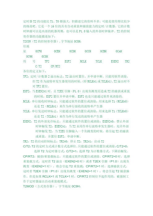
T2的控制寄存器的功能描述如下:T2CON(T2的控制寄存器),字节地址0C8H:位地址 0CFH 0CEH 0CDH 0CCH 0CBH 0CAH 0C9H 0C8H符号 TF2 EXF2 RCLK TCLK EXEN2 TR2 C/T2 CP/RT2各位的定义如下:TF2:定时/计数器2溢出标志,T2溢出时置位,并申请中断。
只能用软件清除,但T2作为波特率发生器使用的时候,(即RCLK=1或TCLK=1),T2溢出时不对TF2置位。
EXF2:当EXEN2=1时,且T2EX引脚(P1.0)出现负跳变而造成T2的捕获或重装的时候,EXF2置位并申请中断。
EXF2也是只能通过软件来清除的。
RCLK:串行接收时钟标志,只能通过软件的置位或清除;用来选择T1(RCLK=0)还是T2(RCLK=1)来作为串行接收的波特率产生器TCLK:串行发送时钟标志,只能通过软件的置位或清除;用来选择T1(TCLK=0)还是T2(TCLK=1)来作为串行发送的波特率产生器EXEN2:T2的外部允许标志,只能通过软件的置位或清除;EXEN2=0:禁止外部时钟触发T2;EXEN2=1:当T2未用作串行波特率发生器时,允许外部时钟触发T2,当T2EX引脚输入一个负跳变的时候,将引起T2的捕获或重装,并置位EXF2,申请中断。
TR2:T2的启动控制标志;TR2=0:停止T2;TR2=1:启动T2C/T2:T2的定时方式或计数方式选择位。
只能通过软件的置位或清除;C/T2=0:选择T2为定时器方式;C/T2=1:选择T2为计数器方式,下降沿触发。
CP/RT2:捕获/重装载标志,只能通过软件的置位或清除。
CP/RT2=0时,选择重装载方式,这时若T2溢出(EXEN2=0时)或者T2EX引脚(P1.0)出现负跳变(EXEN2=1时),将会引起T2重装载;CP/RT2=1时,选择捕获方式,这时若T2EX引脚(P1.0)出现负跳变(EXEN2=1时),将会引起T2捕获操作。
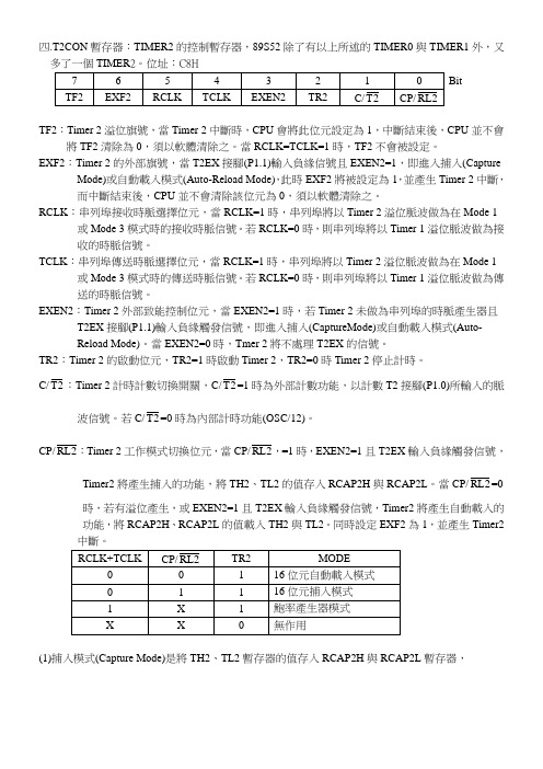
四.T2CON暫存器:TIMER2的控制暫存器,89S52除了有以上所述的TIMER0與TIMER1外,又多了一個TIMER2。
位址:C8HBitTF2:Timer 2溢位旗號,當Timer 2中斷時,CPU會將此位元設定為1,中斷結束後,CPU並不會將TF2清除為0,須以軟體清除之。
當RCLK=TCLK=1時,TF2不會被設定。
EXF2:Timer 2的外部旗號,當T2EX接腳(P1.1)輸入負緣信號且EXEN2=1,即進入捕入(Capture Mode)或自動載入模式(Auto-Reload Mode),此時EXF2將被設定為1,並產生Timer 2中斷,而中斷結束後,CPU並不會清除該位元為0,須以軟體清除之。
RCLK:串列埠接收時脈選擇位元,當RCLK=1時,串列埠將以Timer 2溢位脈波做為在Mode 1 或Mode 3模式時的接收時脈信號。
若RCLK=0時,則串列埠將以Timer 1溢位脈波做為接收的時脈信號。
TCLK:串列埠傳送時脈選擇位元,當RCLK=1時,串列埠將以Timer 2溢位脈波做為在Mode 1 或Mode 3模式時的傳送時脈信號。
若RCLK=0時,則串列埠將以Timer 1溢位脈波做為傳送的時脈信號。
EXEN2:Timer 2外部致能控制位元,當EXEN2=1時,若Timer 2未做為串列埠的時脈產生器且T2EX接腳(P1.1)輸入負緣觸發信號,即進入捕入(CaptureMode)或自動載入模式(Auto-Reload Mode)。
當EXEN2=0時,Tmer 2將不處理T2EX的信號。
TR2:Timer 2的啟動位元,TR2=1時啟動Timer 2,TR2=0時Timer 2停止計時。
C/2T:Timer 2計時計數切換開關,C/2T=1時為外部計數功能,以計數T2接腳(P1.0)所輸入的脈波信號。
若C/2T=0時為內部計時功能(OSC/12)。
CP/2RL,=1時,EXEN2=1且T2EX輸入負緣觸發信號,RL:Timer 2工作模式切換位元,當CP/2Timer2將產生捕入的功能,將TH2、TL2的值存入RCAP2H與RCAP2L。

∙80C52、AT89C52的定时/计数器2∙作者:佚名发布时间:2009-10-30 阅读次数:543 字体大小: 【小】【中】【大】80C52、AT89C52、80C51FA/FB等单片机增加了一个16位定时/计数器T2,可用于定时或外部事件计数。
它有三种工作方式:16位自动重装初值的定时/计数器、捕捉事件、串行口波特率发生器。
与T2有关的外部引脚是:P1。
0-外部计数脉冲输入端T2,P1。
1-外部控制端T2EX。
8052、AT89C52、80C51FA/FB等单片机增加了一个16位定时/计数器T2,可用于定时或外部事件计数。
它有三种工作方式:16位自动重装初值的定时/计数器、捕捉事件、串行口波特率发生器。
与T2有关的外部引脚是:P1。
0-外部计数脉冲输入端T2,P1。
1-外部控制端T2EX。
1、T2的特殊功能寄存器1)控制寄存器T2CON(C8H)位:TF2 EXF2 RCLK TCLK EXEN2 TR2 C//T2 CP//RL2TF2:T2溢出中断标志,在捕捉方式和自动重装初值方式中计数溢出时置1,对应中断入口002BH,但中断响应后,必须由软件清0。
在串行口波特率发生器方式中TF2不会置1。
EXF2:T2外部中断标志。
当EXEN2=1(T2外部中断允许)时,引脚T2EX(P1。
1)的负跳变使EXF2=1,CPU响应中断,入口地址002BH;EXF2也必须由软件清0。
EXEN2:T2外部中断允许标志。
使EXEN2=1,当T2工作在捕捉方式时,引脚T2EX上出现的负跳变使EXF2=1,申请中断,同时TH2、TL2的当前值自动送入RCAP2H、RCAP2L寄存器;如果T2工作在重载初值方式,那么T2EX的负跳变将RCAP2H和RCAP2L的内容自动装入TH2、TL2,同时EXF2=1,申请中断。
EXEN2=0时,T2EX引脚上的变化对T2工作无影响。
RCLK、TCLK:选择串行口波特率发生器方式。

主要性能Array l 与MCS-51单片机产品兼容l 8K字节在系统可编程Flash存储器l 1000次擦写周期l 全静态操作:0Hz~33Hzl 三级加密程序存储器l 32个可编程I/O口线l 三个16位定时器/计数器l 八个中断源l 全双工UART串行通道l 低功耗空闲和掉电模式l 掉电后中断可唤醒l 看门狗定时器l 双数据指针l 掉电标识符功能特性描述A T89S52是一种低功耗、高性能CMOS8位微控制器,具有8K在系统可编程Flash存储器。
使用Atmel公司高密度非易失性存储器技术制造,与工业80C51产品指令和引脚完全兼容。
片上Flash允许程序存储器在系统可编程,亦适于常规编程器。
在单芯片上,拥有灵巧的8位CPU和在系统可编程Flash,使得A T89S52为众多嵌入式控制应用系统提供高灵活、超有效的解决方案。
A T89S52具有以下标准功能:8k字节Flash,256字节RAM,32位I/O口线,看门狗定时器,2个数据指针,三个16位定时器/计数器,一个6向量2级中断结构,全双工串行口,片内晶振及时钟电路。
另外,A T89S52可降至0Hz静态逻辑操作,支持2种软件可选择节电模式。
空闲模式下,CPU 停止工作,允许RAM、定时器/计数器、串口、中断继续工作。
掉电保护方式下,RAM内容被保存,振荡器被冻结,单片机一切工作停止,直到下一个中断或硬件复位为止。
引脚结构方框图引脚功能描述VCC : 电源GND:地P0口:P0口是一个8位漏极开路的双向I/O口。
作为输出口,每位能驱动8个TTL逻辑电平。
对P0端口写“1”时,引脚用作高阻抗输入。
当访问外部程序和数据存储器时,P0口也被作为低8位地址/数据复用。
在这种模式下,P0具有内部上拉电阻。
在flash编程时,P0口也用来接收指令字节;在程序校验时,输出指令字节。
程序校验时,需要外部上拉电阻。
P1口:P1口是一个具有内部上拉电阻的8位双向I/O口,p1输出缓冲器能驱动4个TTL逻辑电平。
AT89C52单片机介绍在众多的单片机系列中,AT89C52是一种低功耗、高性能CMOS8位微控制器,具有8K在系列可编程Flash存储器。
使用Atmel公司高密度非易失性存储器技术制造,与工业80C51产品指令和引脚完全兼容。
片上Flash允许程序存储器在系统可编程,也适用于常规编程。
在单芯片上,拥有灵巧的8位CPU和在系统可编程Flash,使得AT89C52为众多嵌入式控制应用系统提供高灵活、超高效的解决方案。
AT89C52具有以下标准功能:8K字节Flash,256字节RAM,32位I/O口线,3个16位定时器/计数器,一个响亮2级中断结构,全双工串行口,片内晶振及时钟电路。
另外,AT89C52可降至0HZ静态逻辑操作,支持2种软件可选择节电模式。
空闲模式下,CPU停止工作,允许RAM、定时器/计数器、串口、中断继续工作。
掉电保护方式下,RAM内容被保存,振荡器被冻结,单片机一切工作停止,直到下一个中断或硬件复位为止。
AT89C52单片机为很多嵌入式控制系统提供了一种灵活性高且廉价的方案。
故此选用AT89C52单片机。
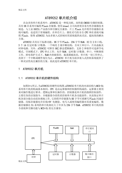
1 AT89C52单片机1.1 AT89C52单片机的硬件结构如图3-1所示,为AT89C52的硬件结构图。
AT89C52单片机的内部结构与MCS-51系列单片机的构成基本相同。
CPU是由运算器和控制器所构成的。
运算器主要用来对操作数进行算术、逻辑运算和位操作的。
控制器是单片机的指挥控制部件,主要任务的识别指令,并根据指令的性质控制单片机各功能部件,从而保证单片机各部分能自动而协调地工作。
它的程序存储器为8K字节可重擦写Flash闪速存储器,闪烁存储器允许在线+5V电擦除、电写入或使用编程器对其重复编程。
数据存储器比51系列的单片机相比大了许多为256字节RAM。
AT89C52单片机的指令系统和引脚功能与MCS-51的完全兼容。
图 3-1 单片机89C52结构框图1.2 主要性能参数• 8K字节可重擦写Flash闪速存储器• 1000次可擦写周期•全静态操作:0Hz-24MHz•三级加密程序存储器• 256×8字节内部RAM• 32个可编程I/O口线• 3个16位定时/计数器• 8个中断源•可编程串行UART通道•低功耗空闲和掉电模式图 3-2 AT89C52外部引脚图1.3 AT89C52管脚说明VCC:电源GND:接地P0口:P0口是一个8位漏级开路的双向I/O口。
第29卷第4期苏 州 大 学 学 报(工 科 版)Vol 129No .42009年8月JOURNAL OF S UZ HOU UN I V ERSI TY (ENGI N EER I N G SC I ENCE ED I TI O N )Aug .2009收稿日期:2009-04-28作者简介:胡学武(1961-),男,高级工程师,主要研究方向为自动化系统应用。
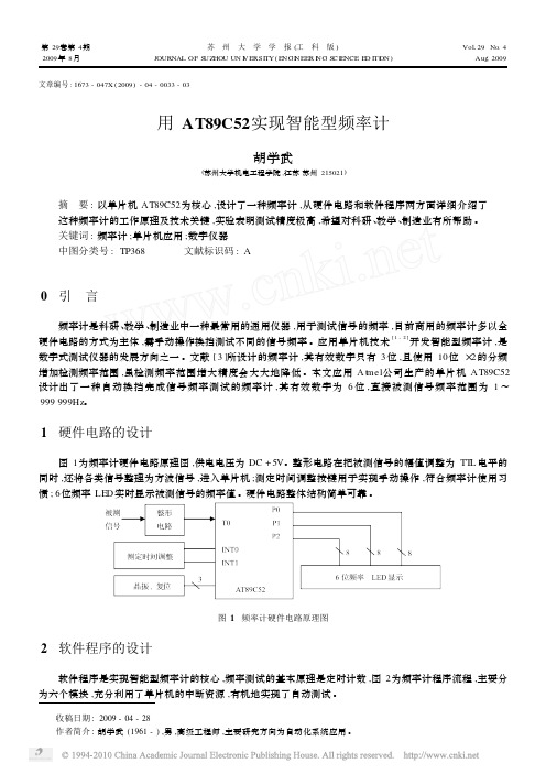
文章编号:1673-047X (2009)-04-0033-03用AT89C52实现智能型频率计胡学武(苏州大学机电工程学院,江苏苏州215021)摘 要:以单片机AT89C52为核心,设计了一种频率计,从硬件电路和软件程序两方面详细介绍了这种频率计的工作原理及技术关键,实验表明测试精度极高,希望对科研、教学、制造业有所帮助。
关键词:频率计;单片机应用;数字仪器中图分类号:TP368 文献标识码:A0 引 言频率计是科研、教学、制造业中一种最常用的通用仪器,用于测试信号的频率,目前商用的频率计多以全硬件电路的方式为主体,需手动操作换挡测试不同的信号频率。
应用单片机技术[1-2]开发智能型频率计,是数字式测试仪器的发展方向之一。
文献[3]所设计的频率计,其有效数字只有3位,且使用10位×2的分频增加检测频率范围,虽检测频率范围增大精度会大大地降低。
本文应用A t m el 公司生产的单片机AT89C52设计出了一种自动换挡完成信号频率测试的频率计,其有效数字为6位,直接被测信号频率范围为1~999999Hz 。
1 硬件电路的设计图1为频率计硬件电路原理图,供电电压为DC +5V 。
整形电路在把被测信号的幅值调整为TT L 电平的同时,还将各类信号整理为方波信号,进入单片机;测定时间调整按键用于实现手动操作,符合频率计使用习惯;6位频率LE D 实时显示被测信号的频率值。
硬件电路整体结构简单可靠。
图1 频率计硬件电路原理图2 软件程序的设计软件程序是实现智能型频率计的核心,频率测试的基本原理是定时计数,图2为频率计程序流程,主要分为六个模块,充分利用了单片机的中断资源,有机地实现了自动测试。
AT89S52 单片机的引脚图及各引脚功能说明由于本书所有的例程均是基于AT89S52 单片机开发的,这里着重介绍AT89S52 各个引脚及功能。
这些关系到在后面学习例程时对原理图的理解,读者要特别重视。
而对于存储器、定时器、中断系统等部分内容,读者可参考介绍MCS-51单片机的相关书籍。
AT89S52 是Atmel公司生产的一种低功耗、高性能CMOS 8位微控制器,具有8 位在系统可编程Flash存储器。
AT89S52 使用Atme公司高密度非易失性存储器技术制造,与工业80C51 产品指令和引脚完全兼容。
片上Flash 允许程序存储器在系统可编程,也适于常规编程器。
在单芯片上,拥有灵巧的8 位CPU 和在系统可编程Flash,使得AT89S52 为众多嵌入式控制应用系统提供高灵活、超有效的解决方案。
AT89S52 具有PDIP、PLCC、TQFP3 种封装形式以适用于不同的使用场合。
各封装引脚定义如图所示。
??图 AT89S52引脚图下面简单介绍AT89S52 各引脚的功能,更多信息请查阅Atmel公司的技术文档。
VCC:电源。
GND:地。
P0 口:P0 口是一个8 位漏极开路的双向I/O 口。
作为输出口,每位能驱动8 个TTL逻辑电平。
对P0 端口写“1”时,引脚用做高阻抗输入。
当访问外部程序和数据存储器时,P0 口也被作为低8 位地址/数据复用。
在这种模式下,P0 具有内部上拉电阻。
在Flash编程时,P0 口也用来接收指令字节;在程序校验时,输出指令字节。
在程序校验时,需要外部上拉电阻。
P1 口:P1 口是一个具有内部上拉电阻的8 位双向I/O 口,P1 输出缓冲器能驱动4 个TT逻辑电平。
当对P1 端口写“1”时,内部上拉电阻把端口拉高,此时可以作为输入口使用。
当作为输入使用时,被外部拉低的引脚由于内部电阻的原因,将输出电流(IIL)。
此外,和分别作为定时器/计数器2 的外部计数输入(T2)和定时器/计数器2的触发输入(T2EX),具体如表1-1 所示。
t a o68PLCC.0(T 2)C .1(T 2E X ).0(AD 0).2(R X D )P .3(A D 3).2(A D 2).3.1(A D 1)(I N T 0)P (T X D )P (T 1)P ()P (T 0)P (((R I N D E X C O R N E .4P P P Features•Compatible with MCS-51™ Products•8K Bytes of In-System Reprogrammable Flash Memory –Endurance: 1,000 Write/Erase Cycles •Fully Static Operation: 0 Hz to 24 MHz •Three-Level Program Memory Lock •256 x 8-Bit Internal RAM •32 Programmable I/O Lines •Three 16-Bit Timer/Counters •Eight Interrupt Sources•Programmable Serial Channel•Low Power Idle and Power Down ModesDescriptionThe AT89C52 is a low-power, high-performance CMOS 8-bit microcomputer with 8K bytes of Flash programmable and erasable read only memory (PEROM). The device is manufactured using Atmel’s high density nonvolatile memory technology and is compatible with the industry standard 80C51 and 80C52 instruction set and pinout.The on-chip Flash allows the program memory to be reprogrammed in-system or by a conventional nonvolatile memory programmer. By combining a versatile 8-bit CPU with Flash on a monolithic chip, the Atmel AT89C52 is a powerful microcomputer which provides a highly flexible and cost effective solution to many embedded control applications.PDIP(T 2)P 1.0V C C(T 2E X )P 1.1P 0.0(A D 0)P 1.2(I N T 0)P 3.2A L E /(R D )P 3.7P 2.3(A 11)(T X D )P 3.1E A /V P P (W R )P 3.6P 2.4(A 12)(R X D )P 3.0P 0.7(A D 7)(T 1)P 3.5P 2.6(A 14)R S TP 0.6(A D 6)P 0.5(A D 5)P 0.4(A D 4)P 0.3(A D 3)P 0.2(A D 2)P 1.3P 0.1(A D 1)(I N T 1)P 3.3X TA L 2P 2.2(A 10)(T 0)P 3.4P 2.7(A 15)X TA L 1P 2.1(A 9)G N DP 2.0(A 8)P 2.5(A 13)P 1.4P 1.5P 1.6P 1.7Pin ConfigurationsPQFP/TQFPI N D E X .0(T 2)C .1(T 2E X ).2.3.0(AD 0).3(A D 3).2(A D 2).1(A D 1)(((4(continued)Block Diagramt a o c h i p.c nAT89C52The AT89C52 provides the following standard features: 8K bytes of Flash, 256 bytes of RAM, 32 I/O lines, three 16-bit timer/counters, a six-vector two-level interrupt architecture, a full duplex serial port, on-chip oscillator, and clock cir-cuitry. In addition, the AT89C52 is designed with static logic for operation down to zero frequency and supports two software selectable power saving modes. The Idle Mode stops the CPU while allowing the RAM, timer/counters, serial port, and interrupt system to continue functioning. The Power Down Mode saves the RAM contents but freezes the oscillator, disabling all other chip functions until the next hardware reset.Pin DescriptionV CCSupply voltage.GNDGround.Port 0Port 0 is an 8-bit open drain bidirectional I/O port. As an output port, each pin can sink eight TTL inputs. When 1s are written to port 0 pins, the pins can be used as high-impedance inputs.Port 0 can also be configured to be the multiplexed low-order address/data bus during accesses to external pro-gram and data memory. In this mode, P0 has internal pul-lups.Port 0 also receives the code bytes during Flash program-ming and outputs the code bytes during program verifica-tion. External pullups are required during program verifica-tion.Port 1Port 1 is an 8-bit bidirectional I/O port with internal pullups. The Port 1 output buffers can sink/source four TTL inputs. When 1s are written to Port 1 pins, they are pulled high by the internal pullups and can be used as inputs. As inputs, Port 1 pins that are externally being pulled low will source current (I IL) because of the internal pullups.In addition, P1.0 and P1.1 can be configured to be the timer/counter 2 external count input (P1.0/T2) and the timer/counter 2 trigger input (P1.1/T2EX), respectively, as shown in the following table.Port 1 also receives the low-order address bytes during Flash programming and verification.Port 2Port 2 is an 8-bit bidirectional I/O port with internal pullups. The Port 2 output buffers can sink/source four TTL inputs. When 1s are written to Port 2 pins, they are pulled high by the internal pullups and can be used as inputs. As inputs, Port 2 pins that are externally being pulled low will source current (I IL) because of the internal pullups.Port 2 emits the high-order address byte during fetches from external program memory and during accesses to external data memory that use 16-bit addresses (MOVX @ DPTR). In this application, Port 2 uses strong internal pul-lups when emitting 1s. During accesses to external data memory that use 8-bit addresses (MOVX @ RI), Port 2 emits the contents of the P2 Special Function Register. Port 2 also receives the high-order address bits and some control signals during Flash programming and verification. Port 3Port 3 is an 8-bit bidirectional I/O port with internal pullups. The Port 3 output buffers can sink/source four TTL inputs. When 1s are written to Port 3 pins, they are pulled high by the internal pullups and can be used as inputs. As inputs, Port 3 pins that are externally being pulled low will source current (I IL) because of the pullups.Port 3 also serves the functions of various special features of the AT89C51, as shown in the following table.Port 3 also receives some control signals for Flash pro-gramming and verification.RSTReset input. A high on this pin for two machine cycles while the oscillator is running resets the device.ALE/PROGAddress Latch Enable is an output pulse for latching the low byte of the address during accesses to external mem-Flash programming.In normal operation, ALE is emitted at a constant rate of 1/6 the oscillator frequency and may be used for external tim-ing or clocking purposes. Note, however, that one ALEPort Pin Alternate FunctionsP1.0T2 (external count input to Timer/Counter2),clock-outP1.1T2EX (Timer/Counter 2 capture/reload triggerand direction control)Port Pin Alternate FunctionsP3.0RXD (serial input port)P3.1TXD (serial output port)P3.2INT0 (external interrupt 0)P3.3INT1 (external interrupt 1)P3.4T0 (timer 0 external input)P3.5T1 (timer 1 external input)P3.6WR (external data memory write strobe) P3.7RD (external data memory read strobe)t a o c h i p.c nt a o c h i p .c npulse is skipped during each access to external data mem-ory.If desired, ALE operation can be disabled by setting bit 0 of SFR location 8EH. With the bit set, ALE is active only dur-ing a MOVX or MOVC instruction. Otherwise, the pin is weakly pulled high. Setting the ALE-disable bit has no effect if the microcontroller is in external execution mode.Program Store Enable is the read strobe to external pro-gram memory.When the AT89C52 is executing code from external pro-gram memory, PSEN is activated twice each machine each access to external data memory.EA/V PPExternal Access Enable. EA must be strapped to GND in order to enable the device to fetch code from external pro-gram memory locations starting at 0000H up to FFFFH.Note, however, that if lock bit 1 is programmed, EA will be internally latched on reset.CC for internal program execu-tions.This pin also receives the 12-volt programming enable volt-age (V PP ) during Flash programming when 12-volt pro-gramming is selected.XTAL1Input to the inverting oscillator amplifier and input to the internal clock operating circuit.XTAL2Output from the inverting oscillator amplifier.Table 1. AT89C52 SFR Map and Reset Values0F8H 0FFH 0F0H B 000000000F7H 0E8H 0EFH 0E0H ACC 000000000E7H 0D8H 0DFH 0D0H PSW 000000000D7H 0C8H T2CON 00000000T2MOD XXXXXX00RCAP2L 00000000RCAP2H 00000000TL200000000TH2000000000CFH 0C0H 0C7H 0B8H IP XX0000000BFH 0B0H P3111111110B7H 0A8H IE 0X0000000AFH 0A0H P2111111110A7H 98H SCON 00000000SBUF XXXXXXXX9FH 90H P11111111197H 88H TCON 00000000TMOD 00000000TL000000000TL100000000TH000000000TH1000000008FH 80HP011111111SP 00000111DPL 00000000DPH 00000000PCON 0XXX000087HAT89C52Special Function RegistersA map of the on-chip memory area called the Special Func-tion Register (SFR) space is shown in Table 1.Note that not all of the addresses are occupied, and unoc-cupied addresses may not be implemented on the chip. Read accesses to these addresses will in general return random data, and write accesses will have an indetermi-nate effect.User software should not write 1s to these unlisted loca-tions, since they may be used in future products to invoke new features. In that case, the reset or inactive values of the new bits will always be 0.Timer 2 Registers: Control and status bits are contained in registers T2CON (shown in Table 2) and T2MOD (shown in Table4) for Timer 2. The register pair (RCAP2H, RCAP2L) are the Capture/Reload registers for Timer 2 in 16-bit capture mode or 16-bit auto-reload mode.Interrupt Registers: The individual interrupt enable bits are in the IE register. Two priorities can be set for each of the six interrupt sources in the IP register.Table 2. T2CON—Timer/Counter 2 Control RegisterData MemoryThe AT89C52 implements 256 bytes of on-chip RAM. The upper 128 bytes occupy a parallel address space to the Special Function Registers. That means the upper 128 bytes have the same addresses as the SFR space but are physically separate from SFR space.When an instruction accesses an internal location above address 7FH, the address mode used in the instruction specifies whether the CPU accesses the upper 128 bytes of RAM or the SFR space. Instructions that use direct addressing access SFR space. For example, the following direct addressing instruction accesses the SFR at location 0A0H (which is P2).MOV 0A0H, #dataInstructions that use indirect addressing access the upper 128 bytes of RAM. For example, the following indirect addressing instruction, where R0 contains 0A0H, accesses the data byte at address 0A0H, rather than P2 (whose address is 0A0H).MOV @R0, #dataNote that stack operations are examples of indirect addressing, so the upper 128 bytes of data RAM are avail-able as stack space.T2CON Address = 0C8H Reset Value = 0000 0000BBit AddressableBit TF2EXF2RCLK TCLK EXEN2TR2C/T2CP/RL2 76543210Symbol FunctionTF2Timer 2 overflow flag set by a Timer 2 overflow and must be cleared by software. TF2 will not be set when either RCLK = 1 or TCLK = 1.EXF2Timer 2 external flag set when either a capture or reload is caused by a negative transition on T2EX and EXEN2 =1. When Timer 2 interrupt is enabled, EXF2 = 1 will cause the CPU to vector to the Timer 2 interrupt routine. EXF2must be cleared by software. EXF2 does not cause an interrupt in up/down counter mode (DCEN = 1).RCLK Receive clock enable. When set, causes the serial port to use Timer 2 overflow pulses for its receive clock in serial port Modes 1 and 3. RCLK = 0 causes Timer 1 overflow to be used for the receive clock.TCLK T ransmit clock enable. When set, causes the serial port to use Timer 2 overflow pulses for its transmit clock in serial port Modes 1 and 3. TCLK = 0 causes Timer 1 overflows to be used for the transmit clock.EXEN2Timer 2 external enable. When set, allows a capture or reload to occur as a result of a negative transition on T2EX if Timer 2 is not being used to clock the serial port. EXEN2 = 0 causes Timer 2 to ignore events at T2EX.TR2Start/Stop control for Timer 2. TR2 = 1 starts the timer.C/T2Timer or counter select for Timer 2. C/T2 = 0 for timer function. C/T2 = 1 for external event counter (falling edge triggered).CP/RL2Capture/Reload select. CP/RL2 = 1 causes captures to occur on negative transitions at T2EX if EXEN2 = 1. CP/RL2 = 0 causes automatic reloads to occur when Timer 2 overflows or negative transitions occur at T2EX when EXEN2= 1. When either RCLK or TCLK = 1, this bit is ignored and the timer is forced to auto-reload on Timer 2 overflow.t a o c h i p.c nTimer 0 and 1Timer 0 and Timer 1 in the AT89C52 operate the same way as Timer 0 and Timer 1 in the AT89C51.Timer 2Timer 2 is a 16-bit Timer/Counter that can operate as either a timer or an event counter. The type of operation is selected by bit C/T2 in the SFR T2CON (shown in Table 2). Timer 2 has three operating modes: capture, auto-reload (up or down counting), and baud rate generator. The modes are selected by bits in T2CON, as shown in Table 3. Timer 2 consists of two 8-bit registers, TH2 and TL2. In the Timer function, the TL2 register is incremented every machine cycle. Since a machine cycle consists of 12 oscil-lator periods, the count rate is 1/12 of the oscillator fre-quency.Table 3. Timer 2 Operating ModesIn the Counter function, the register is incremented in response to a 1-to-0 transition at its corresponding external input pin, T2. In this function, the external input is sampled during S5P2 of every machine cycle. When the samples show a high in one cycle and a low in the next cycle, the count is incremented. The new count value appears in the register during S3P1 of the cycle following the one in which the transition was detected. Since two machine cycles (24 oscillator periods) are required to recognize a 1-to-0 transi-tion, the maximum count rate is 1/24 of the oscillator fre-quency. To ensure that a given level is sampled at least once before it changes, the level should be held for at least one full machine cycle.Capture ModeIn the capture mode, two options are selected by bit EXEN2 in T2CON. If EXEN2 = 0, Timer 2 is a 16-bit timer or counter which upon overflow sets bit TF2 in T2CON. This bit can then be used to generate an interrupt. If EXEN2 = 1, Timer 2 performs the same operation, but a 1-to-0 transition at external input T2EX also causes the cur-rent value in TH2 and TL2 to be captured into RCAP2H and RCAP2L, respectively. In addition, the transition at T2EX causes bit EXF2 in T2CON to be set. The EXF2 bit, like TF2, can generate an interrupt. The capture mode is illus-trated in Figure 1.Auto-Reload (Up or Down Counter)Timer 2 can be programmed to count up or down when configured in its 16-bit auto-reload mode. This feature is invoked by the DCEN (Down Counter Enable) bit located in the SFR T2MOD (see Table 4). Upon reset, the DCEN bit is set to 0 so that timer 2 will default to count up. When DCEN is set, Timer2 can count up or down, depending on the value of the T2EX pin.RCLK +TCLK CP/RL2TR2MODE00116-Bit Auto-Reload01116-Bit Capture1X1Baud Rate GeneratorX X0(Off)Figure 1. Timer in Capture Modet a o c h i p.c nAT89C52Figure 2 shows Timer 2 automatically counting up when DCEN=0. In this mode, two options are selected by bit EXEN2 in T2CON. If EXEN2 = 0, Timer 2 counts up to 0FFFFH and then sets the TF2 bit upon overflow. The over-flow also causes the timer registers to be reloaded with the 16-bit value in RCAP2H and RCAP2L. The values in Timer in Capture ModeRCAP2H and RCAP2L are preset by soft-ware. If EXEN2 = 1, a 16-bit reload can be triggered either by an overflow or by a 1-to-0 transition at external input T2EX. This transition also sets the EXF2 bit. Both the TF2 and EXF2 bits can generate an interrupt if enabled. Setting the DCEN bit enables Timer 2 to count up or down, as shown in Figure 3. In this mode, the T2EX pin controls the direction of the count. A logic 1 at T2EX makes Timer 2 count up. The timer will overflow at 0FFFFH and set the TF2 bit. This overflow also causes the 16-bit value in RCAP2H and RCAP2L to be reloaded into the timer regis-ters, TH2 and TL2, respectively.A logic 0 at T2EX makes Timer 2 count down. The timer underflows when TH2 and TL2 equal the values stored in RCAP2H and RCAP2L. The underflow sets the TF2 bit and causes 0FFFFH to be reloaded into the timer registers. The EXF2 bit toggles whenever Timer 2 overflows or underflows and can be used as a 17th bit of resolution. In this operating mode, EXF2 does not flag an interrupt.Figure 2. Timer 2 Auto Reload Mode (DCEN = 0)Table 4. T2MOD—Timer 2 Mode Control RegisterT2MOD Address = 0C9H Reset Value = XXXX XX00B Not Bit Addressable——————T2OE DCEN Bit76543210Symbol Function—Not implemented, reserved for futureT2OE Timer 2 Output Enable bit.DCEN When set, this bit allows Timer 2 to be configured as an up/down counter.t a o c h i p.c nFigure 3. Timer 2 Auto Reload Mode (DCEN = 1)(DOWN COUNTING RELOAD VALUE)TOGGLET2EX PINFigure 4. Timer 2 in Baud Rate Generator Modet a o c h i p .c nAT89C52Baud Rate GeneratorTimer 2 is selected as the baud rate generator by setting TCLK and/or RCLK in T2CON (Table 2). Note that the baud rates for transmit and receive can be different if Timer 2 is used for the receiver or transmitter and Timer 1 is used for the other function. Setting RCLK and/or TCLK puts Timer 2into its baud rate generator mode, as shown in Figure 4.The baud rate generator mode is similar to the auto-reload mode, in that a rollover in TH2 causes the Timer 2 registers to be reloaded with the 16-bit value in registers RCAP2H and RCAP2L, which are preset by software.The baud rates in Modes 1 and 3 are determined by Timer 2’s overflow rate according to the following equation.The Timer can be configured for either timer or counteroperation. In most applications, it is configured for timer operation (CP/T2 = 0). The timer operation is different for Timer 2 when it is used as a baud rate generator. Normally,as a timer, it increments every machine cycle (at 1/12 the oscillator frequency). As a baud rate generator, however, itincrements every state time (at 1/2 the oscillator fre-quency). The baud rate formula is given below.where (RCAP2H, RCAP2L) is the content of RCAP2H and RCAP2L taken as a 16-bit unsigned integer.Timer 2 as a baud rate generator is shown in Figure 4. This figure is valid only if RCLK or TCLK = 1 in T2CON. Note that a rollover in TH2 does not set TF2 and will not gener-ate an interrupt. Note too, that if EXEN2 is set, a 1-to-0transition in T2EX will set EXF2 but will not cause a reload from (RCAP2H, RCAP2L) to (TH2, TL2). Thus when Timer 2 is in use as a baud rate generator, T2EX can be used as an extra external interrupt.Note that when Timer 2 is running (TR2 = 1) as a timer in the baud rate generator mode, TH2 or TL2 should not be read from or written to. Under these conditions, the Timer is incremented every state time, and the results of a read or write may not be accurate. The RCAP2 registers may be read but should not be written to, because a write might overlap a reload and cause write and/or reload errors. The timer should be turned off (clear TR2) before accessing the Timer 2 or RCAP2 registers.Figure 5. Timer 2 in Clock-Out ModeModes 1 and 3 Baud Rates Timer 2 Overflow Rate16-----------------------------------------------------------=Modes 1 and 3Baud Rate---------------------------------------Oscillator Frequency 3265536RCAP2H RCAP2L (,)–[]×---------------------------------------------------------------------------------------------=t a o c h i p .Programmable Clock OutA 50% duty cycle clock can be programmed to come out on P1.0, as shown in Figure 5. This pin, besides being a regu-lar I/O pin, has two alternate functions. It can be pro-grammed to input the external clock for Timer/Counter 2 or to output a 50% duty cycle clock ranging from 61 Hz to 4MHz at a 16 MHz operating frequency.To configure the Timer/Counter 2 as a clock generator, bit C/T2 (T2CON.1) must be cleared and bit T2OE (T2MOD.1)must be set. Bit TR2 (T2CON.2) starts and stops the timer.The clock-out frequency depends on the oscillator fre-quency and the reload value of Timer 2 capture registers (RCAP2H, RCAP2L), as shown in the following equation.In the clock-out mode, Timer 2 roll-overs will not generate an interrupt. This behavior is similar to when Timer 2 is used as a baud-rate generator. It is possible to use Timer 2as a baud-rate generator and a clock generator simulta-neously. Note, however, that the baud-rate and clock-out frequencies cannot be determined independently from one another since they both use RCAP2H and RCAP2L.UARTThe UART in the AT89C52 operates the same way as the UART in the AT89C51.InterruptsThe AT89C52 has a total of six interrupt vectors: two exter-nal interrupts (INT0 and INT1), three timer interrupts (Tim-ers 0, 1, and 2), and the serial port interrupt. These inter-rupts are all shown in Figure 6.Each of these interrupt sources can be individually enabled or disabled by setting or clearing a bit in Special Function Register IE. IE also contains a global disable bit, EA, which disables all interrupts at once.Note that Table 5 shows that bit position IE.6 is unimple-mented. In the AT89C51, bit position IE.5 is also unimple-mented. User software should not write 1s to these bit posi-tions, since they may be used in future AT89 products.Timer 2 interrupt is generated by the logical OR of bits TF2and EXF2 in register T2CON. Neither of these flags is cleared by hardware when the service routine is vectored to. In fact, the service routine may have to determine whether it was TF2 or EXF2 that generated the interrupt,and that bit will have to be cleared in software.The Timer 0 and Timer 1 flags, TF0 and TF1, are set at S5P2 of the cycle in which the timers overflow. The values are then polled by the circuitry in the next cycle. However,the Timer 2 flag, TF2, is set at S2P2 and is polled in the same cycle in which the timer overflows.Table 5. Interrupt Enable (IE) RegisterFigure 6. Interrupt SourcesClock-Out Frequency Oscillator Fequency465536RCAP2H RCAP2L (,)–[]×-----------------------------------------------------------------------------------------= (MSB) (LSB)EA—ET2ESET1EX1ET0EX0Enable Bit = 1 enables the interrupt. Enable Bit = 0 disables the interrupt.Symbol Position FunctionEAIE.7Disables all interrupts. If EA =0, no interrupt is acknowledged. If EA = 1, each interrupt source is individually enabled or disabled by setting or clearing its enable bit.—IE.6Reserved.ET2IE.5Timer 2 interrupt enable bit.ES IE.4Serial Port interrupt enable bit.ET1IE.3Timer 1 interrupt enable bit.EX1IE.2External interrupt 1 enable bit.ET0IE.1Timer 0 interrupt enable bit.EX0IE.0External interrupt 0 enable bit.User software should never write 1s to unimplemented bits, because they may be used in future A T89 products.AT89C52Oscillator CharacteristicsXTAL1 and XTAL2 are the input and output, respectively, of an inverting amplifier that can be configured for use as an on-chip oscillator, as shown in Figure 7. Either a quartz crystal or ceramic resonator may be used. To drive the device from an external clock source, XTAL2 should be left unconnected while XTAL1 is driven, as shown in Figure 8. There are no requirements on the duty cycle of the external clock signal, since the input to the internal clocking circuitry is through a divide-by-two flip-flop, but minimum and maxi-mum voltage high and low time specifications must be observed.Idle ModeIn idle mode, the CPU puts itself to sleep while all the on-chip peripherals remain active. The mode is invoked by software. The content of the on-chip RAM and all the spe-cial functions registers remain unchanged during this mode. The idle mode can be terminated by any enabled interrupt or by a hardware reset.Note that when idle mode is terminated by a hardware reset, the device normally resumes program execution from where it left off, up to two machine cycles before the internal reset algorithm takes control. On-chip hardware inhibits access to internal RAM in this event, but access to the port pins is not inhibited. To eliminate the possibility of an unexpected write to a port pin when idle mode is termi-nated by a reset, the instruction following the one that invokes idle mode should not write to a port pin or to exter-nal memory.Power Down ModeIn the power down mode, the oscillator is stopped, and the instruction that invokes power down is the last instruction executed. The on-chip RAM and Special Function Regis-ters retain their values until the power down mode is termi-nated. The only exit from power down is a hardware reset. Reset redefines the SFRs but does not change the on-chip RAM. The reset should not be activated before V CC is restored to its normal operating level and must be held active long enough to allow the oscillator to restart and sta-bilize.Figure 7. Oscillator ConnectionsNote: C1, C2 = 30 pF ± 10 pF for Crystals= 40 pF ± 10 pF for Ceramic Resonators Figure 8. External Clock Drive ConfigurationStatus of External Pins During Idle and Power Down ModesXTAL2GNDXTAL1XTAL2 XTAL1 GNDNCEXTERNALOSCILLATORSIGNALMode Program Memory ALE PSEN PORT0PORT1PORT2PORT3 Idle Internal11Data Data Data Data Idle External11Float Data Address Data Power Down Internal00Data Data Data Data Power Down External00Float Data Data Datat a o c h i p.c nProgram Memory Lock BitsThe AT89C52 has three lock bits that can be left unpro-grammed (U) or can be programmed (P) to obtain the addi-tional features listed in the following table.Lock Bit Protection ModesWhen lock bit 1 is programmed, the logic level at the EA pin is sampled and latched during reset. If the device is pow-ered up without a reset, the latch initializes to a random value and holds that value until reset is activated. The at that pin in order for the device to function properly.Programming the FlashThe AT89C52 is normally shipped with the on-chip Flash memory array in the erased state (that is, contents = FFH) and ready to be programmed. The programming interface accepts either a high-voltage (12-volt) or a low-voltage (V CC) program enable signal. The low voltage program-ming mode provides a convenient way to program the AT89C52 inside the user’s system, while the high-voltage programming mode is compatible with conventional third-party Flash or EPROM programmers.The AT89C52 is shipped with either the high-voltage or low-voltage programming mode enabled. The respective top-side marking and device signature codes are listed in the following table.The AT89C52 code memory array is programmed byte-by-byte in either programming mode. To program any non-blank byte in the on-chip Flash Memory, the entire memory must be erased using the Chip Erase Mode. Programming Algorithm: Before programming the AT89C52, the address, data and control signals should be set up according to the Flash programming mode table and Figures 9 and 10. To program the AT89C52, take the fol-lowing steps.1.Input the desired memory location on the addresslines.2.Input the appropriate data byte on the data lines.3.Activate the correct combination of control signals.4.Raise EA/V PP to 12V for the high-voltage programmingmode.5.array or the lock bits. The byte-write cycle is self-timed and typically takes no more than 1.5 ms. Repeat steps1 through 5, changing the address and data for theentire array or until the end of the object file is reached. Data Polling: The AT89C52 features Data Polling to indi-cate the end of a write cycle. During a write cycle, an attempted read of the last byte written will result in the com-plement of the written data on PO.7. Once the write cycle has been completed, true data is valid on all outputs, and after a write cycle has been initiated.Ready/Busy: The progress of byte programming can also be monitored by the RDY/BSY output signal. P3.4 is pulled low after ALE goes high during programming to indicate BUSY. P3.4 is pulled high again when programming is done to indicate READY.Program Verify: If lock bits LB1 and LB2 have not been programmed, the programmed code data can be read back via the address and data lines for verification. The lock bits cannot be verified directly. Verification of the lock bits is achieved by observing that their features are enabled.Program Lock BitsLB1LB2LB3Protection Type1U U U No program lock features.2P U U MOVC instructions executedfrom external programmemory are disabled fromfetching code bytes frominternal memory, EA issampled and latched on reset,and further programming ofthe Flash memory is disabled. 3P P U Same as mode 2, but verify isalso disabled.4P P P Same as mode 3, but externalexecution is also disabled.V PP = 12V V PP = 5VT op-Side Mark A T89C52xxxxyywwA T89C52xxxx-5yyww Signature(030H)=1EH(031H)=52H(032H)=FFH(030H)=1EH(031H)=52H(032H)=05Ht a o c h i p.c n。