野猫云台说明书
- 格式:pdf
- 大小:2.15 MB
- 文档页数:14
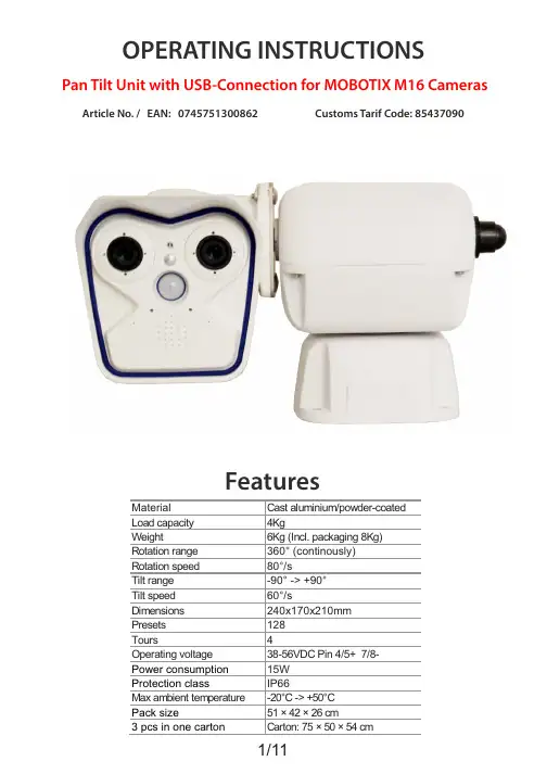
Pan Tilt Unit with USB-Connection for MOBOTIX M16 Cameras Article No. / EAN: 0745751300862 Customs Tarif Code: 85437090INSTRUCTIONSPacking contents1 x Pan & Tilt motor1 x Bag with bolts an screws for mounting the camera1 Passive-PoE AdapterAfter the delivery, check that the packing is not damaged and shows no evident signs of falls or abrasions. If this should be the case, immediately contact the supplier.Check that the contents correspond to the above-mentioned list of materials.Contents of this ManualThis manual describes pan & tilt motors, together with their specific procedures ofinstallation,configuration and use. Read this manual carefully, in particular the chapterconcerning the safety rules, before installing and using the pan & tilt motor.Safety rulesPan & tilt motors comply with the normative laws in force at the time of editing of this manual, concerning electric safety, electromagnetic compatibility and generalrequirements.Anyway, in order to ensure the users (installer, technician and operator), thefollowing warnings are specified for your safety:The appliance (and the complete system, which it belongs to) must be installed onlyby qualified technical staff.The appliance must be opened only by qualified technical staff.The tampering of the appliance may void the guarantee terms.Connect to a device corresponding to the specifications indicated on the data plate(see next chapter Identification data).Before any shifting or technical operations on the appliance, the cables connected toother appliances must be removed.Do not use voltage cables showing wear or ageing, since they may seriously exposurethe users' safety.Do not use the appliance in the presence of inflammable substances.Do not allow children or people not familiar with the appliance to use it.Make sure the appliance is fixed in a solid and reliable way.The appliance is completely off-line only when the cables connected to otherappliances have been removed.For after-Sale service call only authorised technical staff.Keep this manual close to hand for any future reference. Identification dataon pan & tilt motors there is one plate complying with EC specifications.This plate includes:Model identification codeMountingATTENTION: Before powering the P/T-Unit,you have to take notice of the mounting-position.The camera and possible mounting-devices may not come in contact with other parts.All screws must be tightend.The P/T-Unit must be mounted horizontal in all areas.Startup-ProcedureBefore connecting the appliance:Check that the material supplied corresponds to the specifications indicated on the data plate,following the chapter identification data.Check that pan & tilt motor and the other components of the installation are closed in orderto avoid direct contact with energized parts.Check that all the EMC Regulations, valid at the mounting-place, are adhered to and maybe upgrade components to ensure the business-protection and the equipment protection.Make sure that all the parts are fixed in a solid and reliable way.Check that the electrical capacity and the connection cables will support the system powerconsumption.Using unqualified hardware can endanger the security of the staff and installation.Check if the power supplys and cables can handle the consumption.The cables must be connected as shown in this manual.After powering, the Unit has to do a calibration run in horizontal and vertical direction.MaintenanceThe PT-Units don‘t need a special maintenance.We recommend to make a service at the manufactory every 2 years.Connection planThe cables, coming out of the top of the unit, must be connectedwithout benchs and pinch points.(refering to the Mobotix guidelines) LAN 100 MBit/s without PoEincl. 1m MX-OPT-CBL-LAN(optional: 2m / 5m / 10m)PIN-Assignment:Camera:1,2 = 50V PoE +3,6 = 50V PoE -P/T-Unit:4,5 = 50V PoE +7,8 = 50V PoE -Admin MenüNetwork SetupEthernet InterfaceAdmin MenüHardware-ConfigurationManage Hardware Expansions3.Admin MenüSerial InterfaceSetup of serial interface, modem and weather stationAdmin MenüPage AdministrationSoftbuttonsYou can find the Commands for the different Functions on the last Page.Click on a Softbutton, holding the …Shift“-Button6. Calling Presets at predefined Times Admin MenüTransfer ProfilesIP Notify ProfilesData Type: action=putrs232&rs232outtext= z.B. %AO%w.7. TimingAdmin MenüCamera AdminstrationTime TasksIP NOTIFY “HttpRequest“ (Example is on 1 Minute)Control Commands Up RightSlow %FF%01%00%08%00%01%0A Slow %FF%01%00%02%01%00%04 %FF%01%00%08%00%0F%18 %FF%01%00%02%0F%00%12 Medium %FF%01%00%08%00%1F%28 Medium %FF%01%00%02%1F%00%22 %FF%01%00%08%00%2F%38 %FF%01%00%02%2F%00%32 Fast %FF%01%00%08%00%FF%08 Fast %FF%01%00%02%FF%00%02 Down LeftSlow %FF%01%00%10%00%01%12 Slow %FF%01%00%04%01%00%06 %FF%01%00%10%00%0F%20 %FF%01%00%04%0F%00%14 Medium %FF%01%00%10%00%1F%30 Medium %FF%01%00%04%1F%00%24 %FF%01%00%10%00%2F%40 %FF%01%00%04%2F%00%34 Fast %FF%01%00%10%00%FF%10 Fast %FF%01%00%04%FF%00%04 Stop Remote Reset%FF%01%00%00%00%00%01 %FF%01%00%0F%00%00%10Tour Record Start Tour Start1 %FF%01%00%1F%00%00%20 1 %FF%01%00%23%00%00%242 %FF%01%00%1F%00%01%21 2 %FF%01%00%23%00%01%253 %FF%01%00%1F%00%02%22 3 %FF%01%00%23%00%02%264 %FF%01%00%1F%00%03%23 4 %FF%01%00%23%00%03%27Tour Record Stop1 %FF%01%00%21%00%00%222 %FF%01%00%21%00%01%233 %FF%01%00%21%00%02%244 %FF%01%00%21%00%03%25Save Preset 1-32 Call Preset 1-321 %FF%01%00%03%00%01%05 1 %FF%01%00%07%00%01%092 %FF%01%00%03%00%02%06 2 %FF%01%00%07%00%02%0A3 %FF%01%00%03%00%03%07 3 %FF%01%00%07%00%03%0B4 %FF%01%00%03%00%04%08 4 %FF%01%00%07%00%04%0C5 %FF%01%00%03%00%05%09 5 %FF%01%00%07%00%05%0D6 %FF%01%00%03%00%06%0A 6 %FF%01%00%07%00%06%0E7 %FF%01%00%03%00%07%0B 7 %FF%01%00%07%00%07%0F8 %FF%01%00%03%00%08%0C 8 %FF%01%00%07%00%08%109 %FF%01%00%03%00%09%0D 9 %FF%01%00%07%00%09%1110 %FF%01%00%03%00%10%14 10 %FF%01%00%07%00%10%1811 %FF%01%00%03%00%11%15 11 %FF%01%00%07%00%11%1912 %FF%01%00%03%00%12%16 12 %FF%01%00%07%00%12%1A13 %FF%01%00%03%00%13%17 13 %FF%01%00%07%00%13%1B14 %FF%01%00%03%00%14%18 14 %FF%01%00%07%00%14%1C15 %FF%01%00%03%00%15%19 15 %FF%01%00%07%00%15%1D16 %FF%01%00%03%00%16%1A 16 %FF%01%00%07%00%16%1E17 %FF%01%00%03%00%17%1B 17 %FF%01%00%07%00%17%1F18 %FF%01%00%03%00%18%1C 18 %FF%01%00%07%00%18%2019 %FF%01%00%03%00%19%1D 19 %FF%01%00%07%00%19%2120 %FF%01%00%03%00%20%24 20 %FF%01%00%07%00%20%2821 %FF%01%00%03%00%21%25 21 %FF%01%00%07%00%21%2922 %FF%01%00%03%00%22%26 22 %FF%01%00%07%00%22%2A23 %FF%01%00%03%00%23%27 23 %FF%01%00%07%00%23%2B24 %FF%01%00%03%00%24%28 24 %FF%01%00%07%00%24%2C25 %FF%01%00%03%00%25%29 25 %FF%01%00%07%00%25%2D26 %FF%01%00%03%00%26%2A 26 %FF%01%00%07%00%26%2E27 %FF%01%00%03%00%27%2B 27 %FF%01%00%07%00%27%2F28 %FF%01%00%03%00%28%2C 28 %FF%01%00%07%00%28%3029 %FF%01%00%03%00%29%2D 29 %FF%01%00%07%00%29%3130 %FF%01%00%03%00%30%34 30 %FF%01%00%07%00%30%3831 %FF%01%00%03%00%31%35 31 %FF%01%00%07%00%31%3932 %FF%01%00%03%00%32%36 32 %FF%01%00%07%00%32%3A11/11。

红外云台说明书- 1 -目录一、产品概述---------------------------------------------------------------------------- 3二、技术指标---------------------------------------------------------------------------- 3三、性能特点---------------------------------------------------------------------------- 5四、功能说明---------------------------------------------------------------------------- 6五、设备安装连接----------------------------------------------------------------------115.1红外云台外形尺寸----------------------------------------------------------115.2红外云台底座安装孔位尺寸----------------------------------------------125.3航空插座示意图----------------------------------------------------------- 125.4协议、波特率、地址码设置----------------------------------------------135.5壁挂支架、云台安装------------------------------------------------------ 185.6立杆支架、云台安装-------------------------------------------------------195.7 电源连接---------------------------------------------------------------------205.8 外部接线连接---------------------------------------------------------------20六、OSD菜单设置和操作----------------------------------------------------------- 216.1 基本操作---------------------------------------------------------------------216.2 OSD菜单设置和操作总表------------------------------------------------226.3 系统信息设置---------------------------------------------------------------246.4 摄像机参数设置------------------------------------------------------------366.5 自动运行设置---------------------------------------------------------------406.6 语言设置---------------------------------------------------------------------486.7 报警功能设置---------------------------------------------------------------496.8 时钟设置---------------------------------------------------------------------516.9 隐私保护设置---------------------------------------------------------------59七、常用功能设置和调用命令列表------------------------------------------------61八、简易故障排除表------------------------------------------------------------------62- 2 -安全注意事项1. 运输及保管过程中要防止重压、剧烈振动和浸泡等对产品造成的损坏。

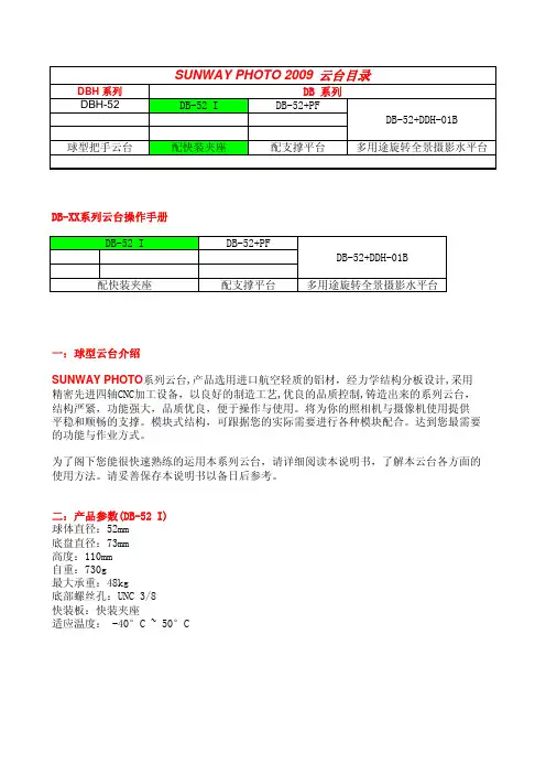
SUNWAY PHOTO 2009 云台目录DBH 系列DB 系列DBH-52DB-52 I DB-52+PFDB-52+DDH-01B 球型把手云台配快装夹座配支撑平台多用途旋转全景摄影水平台DB-XX系列云台操作手册DB-52 I DB-52+PFDB-52+DDH-01B配快装夹座配支撑平台多用途旋转全景摄影水平台一:球型云台介绍SUNWAY PHOTO系列云台,产品选用进口航空轻质的铝材,经力学结构分板设计,采用精密先进四轴CNC加工设备,以良好的制造工艺,优良的品质控制,铸造出来的系列云台,结构严紧,功能强大,品质优良,便于操作与使用。
将为你的照相机与摄像机使用提供平稳和顺畅的支撑。
模块式结构,可跟据您的实际需要进行各种模块配合。
达到您最需要的功能与作业方式。
为了阁下您能很快速熟练的运用本系列云台,请详细阅读本说明书,了解本云台各方面的使用方法。
请妥善保存本说明书以备日后参考。
二:产品参数(DB-52 I)球体直径:52mm底盘直径:73mm高度:110mm自重:730g最大承重:48kg底部螺丝孔:UNC 3/8快装板:快装夹座适应温度: -40°C ~ 50°C三. 云台主要部件介绍DB-52 I配快装夹座1. 快装夹座2. 快装夹座锁紧旋钮3. 防脱落保险扣按钮4. 防脱落保险扣5 水平仪6 主球体7 云台主体8 主锁紧旋钮刻度环9 阻尼调节旋钮10 主锁紧旋钮11 底座锁紧旋钮12 底座刻度圈13 底座螺丝安装孔四:云台与三脚架的连接安装固定好三脚架,先旋转云台底盘锁紧旋钮将底盘锁紧,然后手持云台握紧云台水平底座对准螺纹按螺纹方向拧紧云台。
如果三脚架上连接螺丝标准为UNC1/4-20,则需加装UNC1/4转换UNC3/8螺丝。
五:快装夹座1. 快装夹座2. 快装夹座锁紧旋钮3. 防脱落保险扣按钮4. 防脱落保险扣5 水平仪1:平推装入快装板a. 松开快装夹座锁紧旋钮b. 按卡槽位推入快装板到位c. 拧紧快装板夹座锁紧旋钮2:斜装入快装板a. 松开快装夹座锁紧旋钮b. 斜装入快装板到位c. 拧紧快装板夹座锁紧旋钮备注:快装板需要取出时,先松开少许快装夹座锁紧旋钮,按下保险扣开关才能取出快装板(平推装入时也需要此项操作)六:云台基本功能操作一:1: 握住相机及快装板夹座可任意摆动45度角度进行拍摄。
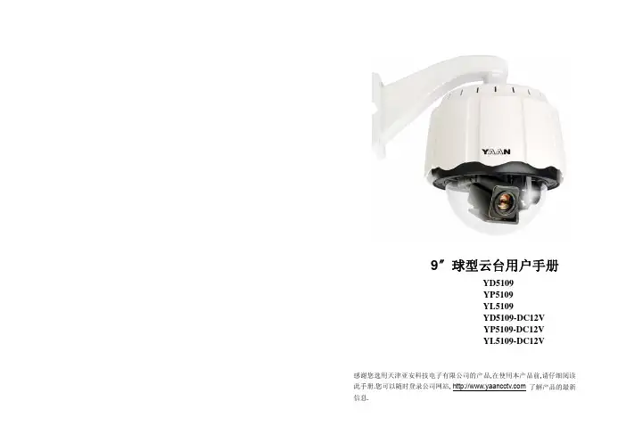
室内外球形云台使用手册USER’S MANUAL中文版球形云台使用说明书尊敬的用户:感谢您选用了我们的产品,我公司此款产品在上一款的基础上,做了许多优化,使产品使用更加稳定,能够适应绝大多数客户的要求。
为使您能更好地使用所选的设备,请认真阅读本说明书,如有问题,请及时反馈给我们或经销商。
再次感谢!产品特点★更新的球罩密封处理,使球罩不仅能防水,更能防尘★重新优化的旋转机芯,使运行更稳定,电机寿命更长久★ ABS双层防晒结构,适合各种环境使用★可拆卸机芯,易于安装调试★金属机芯,结构精致稳固★亚加力光学球罩,透光性好,无变形- 1 -球形云台使用说明书目录一、安全措施 (3)二、使用与维护保养须知 (3)三、云台基本构造及各部名称 (4)四、安装方式 (5)五、安装方法 (6)六、主要技术指标 (7)- 2 -球形云台使用说明书一、安全措施☆不要将装在室内的设备暴露在雨中或潮湿处;☆不要将物品放在设备内,这可能导致短路而损坏设备或系统;☆避免安装在有易燃易爆气体或腐蚀性气体存在的场所;☆不要擅自拆卸云台内部各零部件,其内并无自行修理的零件;☆不要在超出温度,湿度标准的环境使用;☆安装前应阅读说明书,严格按接线图及标签正确接线;☆此云台为 AC24V 供电,请严格确认所接入的电压规格,高于此电压规格的接入将引起设备烧毁。
二、使用与维护保养须知☆在维修及更换或清洁本产品时,请先切断电源。
☆清洁本产品时,请勿使用液体或喷雾型清洁剂,否则将引起内部线路短路。
☆摄像机设备安装完毕后,请及时固定摄像机电源线、视频线及镜头线,以防止云台旋转过程中损坏线缆及云台设备。
☆防止异物留在本设备内。
☆在安装过程中请注意保护透明罩清洁,如不慎弄脏,请用软布和中性清洁剂清洁。
☆安装摄像机时请按照箭头所示方向安装。
☆如遇特殊情况需自行更换零部件时,请与经销商或我公司联系,经认可后方能使用,否则容易造成设备损坏。
☆安装在室外时,请在支架连接处及固定螺钉处做防水处理,防止水分进入设备内部,损坏设备。
Illustra Flex2MP Indoor and OutdoorIR PTZ CamerasQuick Start GuideIllustra Flex2MP Indoor and Outdoor IR PTZ Dome Quick Start GuideNoticePlease read this manual thoroughly and save it for future use before attempting to connect or operate this unit.The information in this manual was current when published.The manufacturer reserves the right torevise and improve its products.All specifications are therefore subject to change without notice. CopyrightUnder copyright laws,the contents of this manual may not be copied,photocopied,reproduced,translated or reduced to any electronic medium or machine-readable form,in whole or in part,without prior written consent of Tyco Security Products.©2018Tyco Security Products.All rights reserved.Tyco Security Products6600Congress AvenueBoca Raton,FL33487U.S.A.Customer ServiceThank you for using American Dynamics products.We support our products through an extensiveworldwide network of dealers.The dealer through whom you originally purchased this product is your point of contact if you need service or support.Our dealers are empowered to provide the very best in customer service and support.Dealers should contact American Dynamics at(800)507-6268or(561)912-6259or on the Web at .TrademarksThe trademarks,logos,and service marks displayed on this document are registered in the UnitedStates[or other countries].Any misuse of the trademarks is strictly prohibited and Tyco SecurityProducts will aggressively enforce its intellectual property rights to the fullest extent of the law,including pursuit of criminal prosecution wherever necessary.All trademarks not owned by TycoSecurity Products are the property of their respective owners,and are used with permission orallowed under applicable laws.Product offerings and specifications are subject to change without notice.Actual products may vary from photos.Not all products include all features.Availability varies by region;contact your salesrepresentative.Table of ContentsIllustra Flex Series2MP Indoor and Outdoor IR PTZ Camera5 Product features5 Product overview5 Installation9 Network Connection13 Default IP Address13 DHCP14 Managing cameras with the Illustra Connect tool15 Appendix A: Technical Specifications17Warning•The Indoor unit operates at PoE+IEEE802.3at or24Vac.The Outdoor unit operates at PoE Ultra802.3bt or24Vac.WARNING:If you do not use an injector which is standard802.3bt then the camera wont work.•Installation and service should be performed only by qualified and experienced technicians and comply with alllocal codes and rules to maintain your warranty.•The camera is not intended to be directly connected to an external network and the video coax connectionsshould only be connected intra-building.•Wipe the camera with a dry soft cloth.For tough stains,slightly apply with diluted neutral detergent and wipe witha dry soft cloth.•Do not apply benzene or thinner to the camera,which may cause the surface of the unit to be melted or lens to be fogged.•ITE is to be connected only to PoE networks without routing to the outside plant.•The power supply shall be approved for ITE NEC Class2or LPS,outdoor=3A minimum,indoor=2A minimumand50degrees Celsius.•Ensure that the safety cable is connected with one end to the ceiling and the other to the safety cable screw on the unit.•Avoid operating or storing the unit in the following locations:•Extremely humid,dusty,or hot/cold environments.Recommended operating temperature is:•Indoor IR PTZ Camera:-20˚C to50˚C(-4˚F to122˚F)•Outdoor IR PTZ Camera:-40˚C to50˚C(-40˚F to122˚F)•Near sources of powerful radio or TV transmitters.•Near fluorescent lamps or objects with reflections.•Under unstable or flickering light sources.WEEE(Waste Electrical and Electronic Equipment).Correct disposal of this product(applicable in the European Union and other European countries with separate collection systems).This product should be disposed of,at the end of its useful life,as per applicable local laws,regulations,and procedures.Illustra Flex2MP Indoor and Outdoor IR PTZ Dome Quick Start GuideIllustra Flex Series2MP Indoor and Outdoor IRPTZ CameraThis chapter provides product features,installation procedures,and connection information regarding the Illustra Flex Series2MP Indoor and Outdoor IR PTZ cameras.Product featuresLens cases require special care when handling and cleaning to avoid scratches.For information oncamera head handling and cleaning,see8200-1174-01Bubble Clearing Procedure Application Note.Go to https:///products.From the Products page,select your camera product range and then select your camera model.Click Downloads and search for Bubble Handling and Cleaning Procedure.Product overviewThis chapter explains the features and installation of the Flex IR PTZ cameras.Product code anddescription of the camera is provided in the table below.Table1Product code and description of the Flex IR PTZ cameraFigure2Physical dimensions of the Flex IR PTZ cameras(mm)Illustra Flex2MP Indoor and Outdoor IR PTZ Dome Quick Start Guide Figure3Physical dimensions of the mount adapterFigure4Pictorial index of the cameraIllustra Flex2MP Indoor and Outdoor IR PTZ Dome Quick Start GuideTable5Pictorial index descriptionsFigure6Pin definitions of the unitTable7Interior button descriptionsFigure8Audio and alarm pin definitionsInstallationIn the boxCheck everything in the packing box matches to the order form and the packing slip.In addition to this guide,items below are included in the packing box:•1Network IR PTZ Camera•1printed Quick Start Guide•1printed Regulatory document•1NTSC/PAL output female BNC cable•12position3mm euro style plug•1Torx20Security L-Key•1Torx6Security L-Key•112-pin terminal connector for I/O function•1Safety cable(Pre-attached to the camera)Contact your dealer if any item is missing.Installation toolsThe following tools assist with installation:•a drill•screwdrivers•wire cuttersChecking appearanceWhen first unboxing,check if there is any visible damage to the appearance of the unit and itsaccessories.The protective materials used for the packaging should be able to protect the unit from most types of accidents during transportation.Remove the protective part of the unit when every item is checked in accordance with the list In the box on page9.Procedure1Accessing the connector pinsRefer to Figure9on page10for a pictorial index of accessing the connector pins.Step Action1Remove the two screws below(1)located on the top cover to open it.Figure9Accessing the connector pins-End-Procedure2Connecting the wiresStep ActionThis unit supports one of the following options as power supply:1Connect a power source:a AC24V wired to connector and seperate RJ45Ethernet.ORb PoE through RJ45connector.2Connect any optional audio or digital inputs or outputs.Note:The power source needs to be NEC Class2or LPS.The Indoor(PoE+IEEE802.3at or24Vac) and Outdoor(PoE Ultra802.3bt or24Vac)connections should be provided by a UL Listed product and the connections shall be made in accordance with Article800of the NEC or local regulations.-End-Illustra Flex2MP Indoor and Outdoor IR PTZ Dome Quick Start GuideProcedure3Mounting the cameraStep Action1Refer to the Illustra mounting accessories webpage(https://www.il-/products/accessories/mounts/)for assistance with this procedure.Note:The following mount accessory part numbers are applicable with the IllustraFlex2MP IR PTZ camera:IFIRPTZWRECMT,IFIRPTZC2X2,RHOSW,RHOLW,RHOTR,ROTRF,RHOWCA,ROENDC.-End-Procedure4Inserting or removing the micro SD CardStep Action1Remove the two screws below(1)located on the micro SD card cover.2Carefully pull open the micro SD card cover to insert or remove the micro SD card into the camera.Figure10Inserting or removing the micro SD CardNote:It is advised that you reboot the camera after inserting the micro SD card.3Secure the two screws located on the micro SD card cover.-End-IR PTZ Camera TopologyThe IR PTZ camera delivers video images in real-time using the internet and intranet.It is equipped with an Ethernet RJ-45network interface.The following images illustrate the network topologies of the cameras.Figure11Flex IR PTZ Cameras Network Topology Type IFigure12Flex IR PTZ Cameras Network Topology Type IINetwork ConnectionDefault IP AddressSince this is a network-based unit,an IP address must be assigned at the very first bootup.The default IP address of the unit is192.168.1.168and sub mask is255.255.255.0.However,if you have a DHCP server in your network,the unit obtains an IP address automatically from the DHCP server so that you do not need to change the IP address of the camera.Note:If you assign the camera a Static IP address prior to DHCP being enabled,the camera first reboots for approximately30seconds and then remains accessible at its Static IP until it connects toa DHCP server.•Connect to a PC directly:Directly connect the camera to a PC using a standard Ethernetcable.This requires POE switch or injector.•Connecting a camera to a Local Area Network(LAN):To add the camera to an existingLAN,connect the camera to the POE hub or switch on your network.Figure13Network connection diagramDefault camera settingsThe following table describes the default camera settings.Note:At first login the user is prompted to change the default username and password.Illustra Flex2MP Indoor and Outdoor IR PTZ Dome Quick Start GuideProcedure5Connecting from a computerStep Action1Ensure the camera and your computer are in the same subnet.2Check whether if the network is available between the unit and the computer by pinging the default IP address.a Start a command prompt.b Type“Ping192.168.1.168”.If the message“Reply from…”appears,it means the con-nection is available.3Start Internet Explorer and enter IP address:192.168.1.168.A login window appears.In the window,enter the default user name:admin and password:admin to log in.-End-DHCPOn initial camera startup,and after a hardware factory reset,Dynamic Host Configuration Protocol(DHCP)is enabled by default and remains enabled until the camera receives either a DHCP address or is assigned a Static IP address.Procedure6Enable DHCPStep Action1Select Setup on the Web User Interface banner to display the setup menus.2Select the TCP/IP tab in the Basic Configuration menu.3Select the Enable DHCP check box to enable DHCP and disable manual settings.4Select Apply to save the settings.The camera searches for a DHCP server.If one is found it connects to that server.If no connection is made to a DHCP server within two minutes,the camera goes to the default IP address192.168.1.168,but continues to search for a DHCP address.Note:If you assign the camera a Static IP address prior to DHCP being enabled,the camera firstreboots for approximately30seconds and then remains accessible at its Static IP until it connects toa DHCP server.-End-Procedure7Disable DHCPStep Action1Select Setup on the Web User Interface banner to display the setup menus.2Select the TCP/IP tab in the Basic Configuration menu.3Clear the Enable DHCP check box to disable DHCP and allow manual settings to be entered.The default setting is‘Enabled’.4If Enable DHCP has been disabled:Illustra Flex2MP Indoor and Outdoor IR PTZ Dome Quick Start Guidea Enter the IPv4Address in the IPv4Address text box in the form xxx.xxx.xxx.xxx.Thedefault setting is‘192.168.1.168’b Enter the Network Mask in the Network Mask text box xxx.xxx.xxx.xxx.The defaultsetting is‘255.255.255.0’c Enter the Gateway IP address in Gateway text box xxx.xxx.xxx.xxx.d Enter the Primary DNS Server in the Primary DNS Server text box xxx.xxx.xxx.xxx.5Select Apply to save the settings.-End-Managing cameras with the Illustra Connect toolIn addition to using the IE browser to access your camera,you can alternatively use the provided tool,Illustra Connect.Illustra Connect is a management tool designed to manage your network cameras on the LAN.It can:•help you find multiple network cameras•set the IP addresses•show connection status•manage firmware upgrades•bulk configurationProcedure8Connecting to the camera using Illustra ConnectNote:Illustra Connect can only discover devices on the same subnet as its host computer.Therefore,the camera and the computer being used to configure it must be on the same subnet.Step Action1Using a computer which is connected to the same network and subnet,install the Illustra Connect software.The Illustra Connect software and the Illustra Connect manual are available to download on2When the installation is complete,run Illustra Connect.It searches the network and displays all compliant devices.3Select the camera you want to configure,locating it by its unique MAC address.4Right-click the camera and select Launch Web GUI Configuration.The camera Web User Interface displays.-End-Illustra Flex2MP Indoor and Outdoor IR PTZ Dome Quick Start GuideProcedure9Connecting to the camera using the static IP addressStep Action1The camera attempts to obtain an IP Address from the DHCP Server.When no DHCP Server is available the camera is assigned a Static IP address of192.168.1.168.2Open Microsoft Internet Explorer and enter the URL of the camera as192.168.1.168.The camera sign in page displays.Note:The computer you use to configure the camera must have an IP address on the same subnet.-End-Procedure10Logging on to the camera web user interfaceStep Action1When you select the camera,the sign in page displays.Select your preferred language from the drop-down menu.2Enter the username in the Username text box.The default username is admin.3Enter the password in the Password text box.The default password is admin.4Select Log in.Note:The first time that you access the camera or after a factory reset the following two pop upwindows are visible:A pop up window that requests the user to Define a Host ID and a pop upwindow that requests the user to select a Security Type.Please refer to the user manual for further information on this.5The Live view page is visible.This displays the current view of the camera.Note:At first login the user is prompted to change the default username and password.-End-Illustra Flex2MP Indoor and Outdoor IR PTZ Dome Quick Start Guide Appendix A:Technical SpecificationsThe table below lists technical specifications of the Flex2MP Indoor and Outdoor IR PTZ cameras.Illustra Flex2MP Indoor and Outdoor IR PTZ Dome Quick Start GuideIllustra Flex2MP Indoor and Outdoor IR PTZ Dome Quick Start GuideIllustra Flex2MP Indoor and Outdoor IR PTZ Dome Quick Start GuideIllustra Flex2MP Indoor and Outdoor IR PTZ Dome Quick Start GuideIllustra Flex2MP Indoor and Outdoor IR PTZ Dome Quick Start GuideTable14Flex2MP IR PTZ Stream TablesTWDR Off TWDRResolution Codec FPS range FPSrangeStream1(1920x1080)1080p16:9H264/H264IntelliZipH265/H265Intellizip MJPEG 1-601-30(1664x936)16:9 (1280x720)720p16:9Stream2 (1280x720)720p16:9H264/H264IntelliZip H265/H265Intellizip MJPEG 1-30or1-15*11-30(1024x576)PAL+16:9(640x360)nHD16:9(480x360)4804:3(384x288)4:3Stream3(640x360)nHD16:9MJPEG*27-157-15(480x360)4804:3(384x288)4:3Note:*1-Stream2is restricted to15FPS when Stream1is greater than30FPSNote:*2-Stream3is restricted to MJPEG only.Note:A maximum of five concurrent streams are supported by each camera,this includes shared streams.(Example:Stream1can be shared three times along with a running Stream2and Stream3, or Stream1can be shared five times).Note:TWDR limits the stream to not exceed30FPS even if the stream is configured to31+FPS. Note:TWDR3x is not supported for the PTZ camera.。
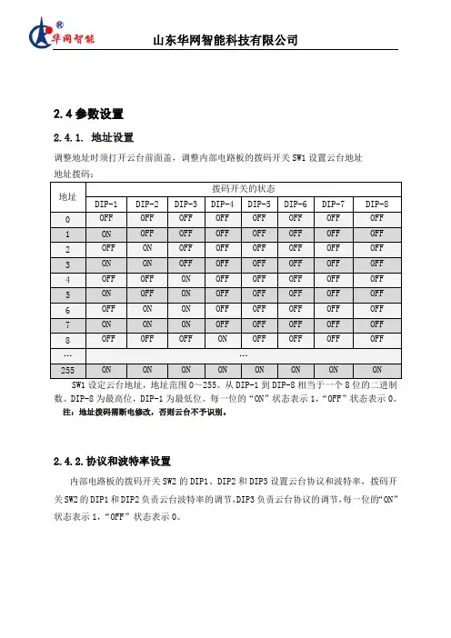
2.4参数设置2.4.1. 地址设置调整地址时须打开云台前面盖,调整内部电路板的拨码开关SW1设置云台地址地址拨码:SW1设定云台地址,地址范围0~255。
从DIP-1到DIP-8相当于一个8位的二进制数。
DIP-8为最高位,DIP-1为最低位。
每一位的“ON”状态表示1,“OFF”状态表示0。
注:地址拨码需断电修改,否则云台不予识别。
2.4.2.协议和波特率设置内部电路板的拨码开关SW2的DIP1、DIP2和DIP3设置云台协议和波特率,拨码开关SW2的DIP1和DIP2负责云台波特率的调节,DIP3负责云台协议的调节,每一位的“ON”状态表示1,“OFF”状态表示0。
2.4.3 巡航预置位设置内部电路板的拨码开关SW2的DIP4设置云台巡航状态,当云台配合镜头正常使用巡航功能时DIP4拨到OFF状态,如果云台不接镜头单独测试巡航功能时DIP4拨到ON 状态。
单独测试云台时与镜头连接正常使用时2.4.4误差选择位内部电路板的拨码开关SW2的DIP5和DIP6用于云台水平方向误差微调,DIP7用于云台俯仰方向误差微调,一般云台出厂时已被设置成最佳效果,用户不需要重新设置。
2.4.5常用操作说明后端控制方式主要有键盘与软件两种控制方式,但由于键盘、控制软件种类较多,统一性较差,此处只列举较常见控制功能,见下表:或或或或或或2.4.6增强性功能(标准云台)●辅助开关的打开与关闭1、1+AUX+ON/OFF 调用/关闭1号辅助开关2、2+AUZ+ON/OFF 调用/关闭2号辅助开关●巡航时间设置1、100+SHOT+ON 设置巡航各点间停留时间为04秒;2、101+SHOT+ON 设置巡航各点间停留时间为10秒;3、102+SHOT+ON 设置巡航各点间停留时间为20秒;4、103+SHOT+ON 设置巡航各点间停留时间为30秒;5、104+SHOT+ON 设置巡航各点间停留时间为1min;6、105+SHOT+ON 设置巡航各点间停留时间为2min;7、106+SHOT+ON 设置巡航各点间停留时间为3min;8、107+SHOT+ON 设置巡航各点间停留时间为4min;●巡航调用1、100+SHOT+ACK 打开第1条巡航线,调用1到10号预置位;…………2、107+SHOT+ACK 打开第8条巡航线,调用71到80号预置位;●守望功能的实现112+SHOT+ACK 打开自动归位功能,云台会在所有动作结束后在设定的时间自动调用1号预置位;113+SHOT+ACK 关闭自动归位功能;●守望功能时间的设定81+SHOT+ON 设定自动归位时间1min;82+SHOT+ON 设定自动归位时间2min;83+SHOT+ON 设定自动归位时间5min;84+SHOT+ON 设定自动归位时间10min;85+SHOT+ON 设定自动归位时间15min;86+SHOT+ON 设定自动归位时间20min;87+SHOT+ON 设定自动归位时间30min;88+SHOT+ON 设定自动归位时间40min;89+SHOT+ON 设定自动归位时间50min;90+SHOT+ON 设定自动归位时间60min;●线扫设置与调用(符合PELCO扩展命令,见附件)1、110+SHOT+ON 设置线扫起点;2、111+SHOT+ON 设置线扫终点;3、110+SHOT+ACK 打开线扫功能;4、111+SHOT+ACK 关闭线扫功能;●云台参考点设置设置0号预置位设置成功后,将以云台0号预置位所在的位置作为参考点,即云台角度回传及云台角度定位的参考基准点,此功能不会影响云台之前所设置的预置位,云台开机自检完成后会自动调回0号预置位。
IPEL-P5030X-IRW15 Megapixel Outdoor, Full-Size 30× Network IR PTZ Dome Camera●1/1.9" 5 Megapixel STARVIS™ CMOS ●Powerful 30x optical zoom ●H.265 Encoding●Max. 20fps@6M, 25/30fps@5M/3M(Realtime)●Auto tracking and IVS ●Supports Hi-PoE●IR distance up to 200m ●IP67Auto-trackingThis feature controls the pan/tilt/zoom actions of the camera to automatically track an object in motion and to keep it in the scene. The tracking action can be triggered manually or automatically by defined rules. Once a rule is triggered, the camera can zoom in and track the defined target automatically.HEVC (H.265)The H.265 (ITU-T VCEG) video compression standard offers double the data compression ratio at the same level of videoquality, or substantially improved video quality at the same bit rate, as compared to older video compression technologies. H.265 offers such impressive compression by expanding the pattern comparison and difference coding, improving motion vector prediction and motion region merging, and incorporating an additional filtering step called sample-adaptive offset filtering.A new, and sleek designed PTZ, with the critically acclaimed Advanced Intelligence Video Analytics - the IPEL-P5030X -IRW1 PTZ camera.This camera is a fully weatherproof, day/night, high resolution IP camera. This PTZ adopts a unique design by physically separating the IR LEDs from the camera block itself, resulting in perfect night time imaging without causing issues such as IR reflection. The optics on this camera are a 30X powered zoom (6 - 180MM), delivering a crystal clear 5 Megapixel image. 0 lux is not a problem for this camera, as the high intensity IR LED's are capable of illumination at distances up to 300’.This camera itself is ONVIF Profile S compliant, and can work as a standalone camera, or in conjunction with an NVR to achieve longer recording durations. By complying with ONVIF specifications, this device is also well suited to integrate with a wide array of VMS.System OverviewFunctionsPFA TechnologyPFA technology has innovatively introduced new methods ofjudgment to ensure the accuracy and predictability of the direction of subject distance adjustment. The result is a set of advanced focusing algorithms. PFA ensures clarity of the image throughout the process of zooming and shortens focus time. The realization of PFA technology substantially improves user experience and increases product value.EnvironmentalWith a temperature range of -40 °C to +70 °C (-40 °F to +158 °F), the camera is designed for extreme temperature environments. Subjected and certified to rigorous dust and water immersion tests, the IP67 rating makes it suitable for demanding outdoor applications.ProtectionThe camera allows for ±25% input voltage tolerance, suitable for the most unstable conditions for outdoor applications. Its 8KV lightning rating provides effective protection for both the camera and its structure against lightning.InteroperabilityThe camera conforms to the ONVIF (Open Network VideoInterface Forum) specifications, ensuring interoperability between network video products regardless of manufacturer.Technical SpecificationImage Sensor 1/1.9” STARVIS™ CMOS Effective Pixels 2560(H) x 1920(V), 5 Megapixels RAM/ROM1024M/128M Scanning System Progressive Electronic Shutter Speed 1/1s~1/30,000s Minimum Illumination Color:************;B/W:*************;*********(IRon)IR Distance Distance up to 656ft (200m)IR On/Off Control Auto / Manual IR LEDs 10WiperSupportLens Type 6mm~180mm Max. Aperture F1.6 ~ F4.3Angle of View H: 61.2° ~ 2.1° Optical Zoom 30xFocus Control Auto/Manual Close Focus Distance100mm~ 1000mm DORI DistanceDetectObserve Recognize Identify 7832ft 2953ft 1476ft 738ft 2250m900m450m225mLensCameraPan/Tilt Range Pan: 0° ~ 360° endless; Tilt: -20° ~ 90°,auto flip 180°Manual Control Speed Pan: 0.1° ~240° /s; Tilt: 0.1° ~120° /s Preset Speed Pan: 240° /s; Tilt: 200° /s Presets 300PTZ Mode 5 Pattern, 8 Tour, Auto Pan ,Auto ScanSpeed Setup Human-oriented focal Length/ speed adaptation Power up Action Auto restore to previous PTZ and lens status after power failureIdle Motion Activate Preset/ Scan/ Tour/ Pattern if there is no command in the specified period ProtocolICR-SD, Pelco-P/D (Auto recognition)PTZEvent Trigger Motion detection, Video tampering , Scene changing, Network disconnection, IP address conflict, Illegal Access, Storage anomaly Auto Tracking SupportIVSTripwire, Intrusion, Abandoned/Missing Object Advanced Intelligent FunctionsFace Detection, Heat MapIntelligenceCompression H.265+/H.265/H.264+/H.264Streaming Capability 3 StreamsResolution6M(3072x2048)/5M(2560×1920)/3M(2048×1536)/108 0P(1920×1080)/1.3M(1280×960)/720P(1280×720)/D1 (704×576/704×480)/CIF(352×288/352×240)Frame RateMain stream: 6M(1~20fps)/5M/3M(1~25/30fps), 1080P/1.3M/720P(1~50/60fps)Sub stream1: D1/CIF(1 ~ 25/30fps)Sub stream2: 5M/1080P/1.3M/720P/D1/CIF (1~25/30fps)Bit Rate ControlCBR/VBRVideoBit Rate H.265/H.264: 448K ~ 8192Kbps Day/NightAuto(ICR) / Color / B/W Backlight Compensation BLC / HLC / WDR(120dB)White Balance Auto, ATW, Indoor, Outdoor, Manual Gain Control Auto / Manual Noise Reduction Ultra DNR (2D/3D)Motion Detection Support Region of InterestSupport Electronic Image Stabilization (EIS)Support Defog Support Digital Zoom 16x Flip180°Privacy MaskingUp to 24 areasCompressionG.711a/G.711Mu/AAC/G.722/ G.726/MPEG2-L2AudioEthernet RJ-45 (10Base-T/100Base-TX)Protocol IPv4/IPv6, HTTP, HTTPS, SSL, TCP/IP, UDP, UPnP, ICMP, IGMP, SNMP, RTSP, RTP, SMTP, NTP, DHCP, DNS,PPPOE,DDNS,FTP, IP Filter,QoS,Bonjour,802.1x Interoperability ONVIF Profile S&G, CGI Streaming Method Unicast / Multicast Max. User Access 20 usersEdge StorageNAS (Network Attached Storage),Local PC for instant recording, Micro SD card 256GB Web ViewerIE, Chrome, Firefox, Safari Management Software SmartICRSS, DSS Smart PhoneIOS, AndroidNetworkCertificationsCE: EN55032/EN55024/EN50130-4; FCC: Part15 subpartB,ANSI C63.4- 2014UL: UL60950-1+CAN/CSA C22.2,No.60950-1CertificationsVideo Interface 1 port(BNC, 1.0V[p-p], 75Ω)Audio Interface1/1 channel In/Out RS4851Alarm I/O7/2InterfacePower Supply AC24V/3A(±25%), Hi-PoE Power Consumption24W, 38W (IR on)ElectricalOperating Conditions -40° C ~ +70° C (-40° F ~ +158° F) / Less than 95% RH Storage Conditions -40° C ~ +70° C (-40° F ~ +158° F) / Less than 95% RH Ingress Protection IP67Vandal ResistanceN/AEnvironmentalCasing MetalDimensions Φ9.45” x 15.04”(240mm x 382mm)Net Weight 14.88lb(6.75kg)Gross Weight22.27lb(10.1kg)ConstructionAccessories Dimensions (mm/in)。
云台使用说明书本文档描述了DVR里的一个主要功能——云台控制的设置。
主要功能包括:控制云台方向、速度、变倍、聚焦、光圈,预置点、点间巡航、轨迹巡视、边界扫描、旋转、云台复位等通过下列途径找到该设功能设置的界面:直接在预览界面上点击鼠标右键,找到【云台控制】,界面如图1所示:图1前提条件1.操控前,请确认球机的A、B线与硬盘录像机的A、B接口连接正确,连接线上有注明A线和B线,用户进行连接时要先查看线的接口2.云台支持的功能项,由云台协议支持的功能项决定,即由用户所购买的球机的功能决定。
3.操控前,请先右键【主菜单】>左键【摄像机】>选择【云台设置】,设置云台参数,云台设置的界面如下图2(里面的参数是默认值)图2“云台参数”在刚打开球机的时候,预览界面上有显示,显示界面如下图3:图3在云台设置,上图2中首先选择“通道号”,接着设置步骤如下:图2中云台协议对应图3中控制协议,在云台协议的下拉框中选择协议:PELCO_D1图2中云台地址对应图3中的球机地址,在云台地址的文本框中输入球机地址:0图2中的【波特率】、【数据位】、【停止位】、【校验】分别对应图3中的9600、、8、1,N(意思是无),在图2云台设置界面中填写对应下拉框,选择对应的参数。
设置好后按【保存】,对应参数的界面如图4:图4上图4表示已经设置好通道1的云台参数,退出设置界面,右键云台控制就可以控制第一通道的云台了注:1)云台控制的通道须连接云台视频2)球机的A、B线与硬盘录像机的A、B接口连接正确功能细化右键云台控制,进入云台控制界面,如下图5:图5常规选项【控制云台方向】鼠标操控云台转动,支持8个方向控制(前面板只支持4个方向操控),用户直接用鼠标点击界面上云台的方向键,球就会根据用户的点击而转动;用户按住鼠标左键不放,球机会一直转动注意:球机有上下左右的最大限度,不能一直向一个方向转动,出现点击向上云台不会动,点击往下方向查看,排除由于限度原因导致云台不动【变倍】通过/键调节摄像头放大倍数;【聚焦】通过/键调节摄像头进行聚焦;【光圈】通过/键调节摄像头光圈;【进度条】用于设置云台转动的幅度(转动的快慢),数字越大,幅度越大,速度越快,设置范围:0~~15预置点设定某方位为预置点,调用该预置点值,云台自动转动到设定方位。
云台解码器使用说明书云台解码器使用说明书云台解码器使用说明书使用说明书中文版第一版地址拨码开关地址拨码开关地址拨码开关 1 2 3 4 5 6 1 2 3 4 5 6 1 2 3 4 5 6Copyright 2002-2010. Kingvee All Rights Reserved. 一技术参数工作电压AC 24V?10、50HZ/60HZ。
工作电流输入交流1850MA含云台电流。
环境温度全天候、- 30? 70?、相对湿度 90RH。
镜头电压DC 12V和DC6V、电流200MADC6V/DC12V通过板上跳线帽选择。
镜头控制光圈、聚焦、变倍。
云台电压AC24V/1000MA、云台控制上、下、左、右、自动左上、左下、右上、右下。
摄像机电源DC 12V/500MA。
通信接口标准RS485自带120欧终端电阻。
支持协议多种常用协议可为用户定制协议。
地址数量64个地址可扩充加设备。
板尺寸80X90mm。
二系统概述 1解码器是与监控系统配套使用的一种前端控制设备可控制球机、室内外交流24V云台、电动三可变电压为6V或12V镜头提供摄像机电源等。
2使用通用的RS485通讯接口兼容多种常用的控制协议自带120欧匹配电阻。
3可提供稳定的12V直流电源500MA供摄像机及红外灯使用。
4具有超强的防雷、抗死机性能性价比极高适用于各款数字硬盘录像系统、矩阵系统、键盘、PC 控制等设备。
三云台 1可控制云台的种类可控制全球和半球的内置式云台、普通型云台、以及其它特殊型号的云台和室内外全方位云台的上、下、左、右和自动运行支持左上、左下、右上、右下室内外水平云台的左、右和自动运行。
2云台电压本机支持24 V的交流云台不支持“AC220V”的云台。
3云台的保险措施本机使用自恢复保险丝如云台接错线即云台控制线的公共线接到其它的接口上如自动、上、下、左、右云台工作时自恢复保险丝就会自动关断电路保护云台不致烧毁。
Copyright(C)2019(edición V2.0)PrefacioGracias por la compra de nuestros productos.no dude en ponerse en contacto con nosotros si tiene alguna pregunta o necesidades.El propósito de esta sección es asegurar que el usuario puede utilizar correctamente el producto a través de este manual para evitar el peligro durante el funcionamiento o daños materiales.Antes de utilizar este producto,lea el manual del producto con cuidado y guárdelo para futuras consultas.DeclaraciónLas fotografías y descripciones proporcionadas en este manual pueden diferir de su versión actual.Si tiene alguna pregunta al usar este manual, póngase en contacto con nuestro soporte técnico para obtener ayuda.El contenido de este manual se actualizaráde vez en cuando,y las reservas de la compañía el derecho que le mantenga informado.ContenidoCapítulo1.Breve introducción (3)1.1Descripción del producto (3)1.2Características del producto y de la Función (3)Capítulo2.Instalación del dispositivo (3)2.1Montaje de techo (3)2.2Soporte de pared montado (4)2.3Esquema de conexiónde cable (5)2.4Diagrama común topología del sistema (6)Capítulo3.Operación y Control PTZ (6)3.1Configuración por defecto (6)3.3Comandos comunes de operación PTZ (7)Capítulo4.Preguntas y respuestas (8)Capítulo1.Perfil del productoDescripción del producto1.1Esta mini cámara domo PTZ poner la función PTZ de alta resolución,luz de las estrellas y como uno de el más reciente cámara PTZ domo.Fácil de instalar y utilizar,no requiere cableado integrado tedioso.Eso soportes preestablecido,otra función básica.Construido en la plataforma de PTZ y adopta unidad de motor de precisión.Respuesta sensible, operación suavizar y no movimiento de la imagen.Construido en la lente de zoom luz de las estrellas y de4piezas IR luces para asegurarse de que la visión nocturna inteligente.Eso apoya I.CVI y CVBS salida del modelo4 de señal.Puede ser ampliamente utilizado en pequeña controlar la aplicación,tales como almacén,aparcamiento,supermercados,escaleras,centros comerciales y otros lugares al aire libre o en interiores.1.2Características del producto y de la FunciónEsta cámara domo PTZ serie de mini caja de metal usando+PC,transparente a prueba de explosiones y la caja exterior PC anti-arañazos,engranaje helicoidal de motor de precisión,control multifunción.Adoptar sensores megapíxel,la imagen es clara y delicada. salida de video HD de apoyo.Apoyar obturador electrónico,adaptarse a diferentes entornos de monitorización.Soporte IR-corte de infrarrojos conmutación automática del filtro para lograr día y noche de monitorización.Apoyar220x preestablecido y1x AB escanear.Capítulo2.Instalación del producto2.1Montaje de techo2.1.1Fije el soporte a la pared,de acuerdo con la posición del orificio fijo en elsoporte de hacer una marca buena,y pulsa la posición del agujero de montaje(cada lado tiene3agujeros de montaje,que puede bajo el actual situación paraelegir la mejor instalación conveniente perforación de orificios vacía.Instalar untornillo de fijación en cada lado.2.1.2Uso de los tornillos para fijar el soporte de montaje en el techo de acuerdocon la posición del agujero recién mecanografiado(prestar atención a la toma de corriente cuando se instala el no-techo)2.1.3Coloque la base de la cámara con el soporte instalada,gire a la derecha paraapretarlo,y luego solucionarlo.2.2Soporte montaje de pared2.2.1Fije el soporte a la pared,se marca de acuerdo a la posición del orificio fijo enel soporte,y dio en el orificio de montaje asímordió2.2.2Fije la cámara a la paredsoporte,prestar atención a la cola de cable a travésdel soporte y,a continuación,girar en sentido horario de la cámara a la partesuperior de la posición del agujero de tres tornillos,y bloquear los tornillos.2.2.3Coloque el soporte de pared de la cámara de bloqueo en el orificio de montajerecién escrito,apretar los tornillos,y asegurar el soporte de montaje en pared. 2.3Esquema de conexión de cableResistenciafotosensibleLente de la cámaraLámpara de infrarrojosx4Todo cáscara de la aleación de aluminioConmutador DIPInterfaz BNCInterfaz de alimentación de CCInterfaz RS485Conexión eléctricaMarca:por favor revise cuidadosamente el voltaje y la corriente nominal de la siguiente manera: Tensión nominal Rango de tensión nominal Corriente DC12V Más o menos10%2ADip switchMarca:Esto apoya la cámarade salida demodo4de señal(AHD/TVI/CVI/CVBS)que se puedeactivar a través de DIP.CVI Análogo AHD TVIEN12HDEN12EN12EN12HDCámara HD domo analógicasMonitorLínea VGAlínea devídeocoaxial RS485LineDiagrama de topología 2.4Sistema comúnDVR Teclado de control analógicoCapítulo 3.Operación y Control PTZ3.1Configuración de preseta)Máximo de pre ajustes guardados 220.b)Se acciona el botón de dirección del PTZ,ajustar la pantalla de la lente a laposición de donde se desea controlar,a continuación,seleccionar el número predeterminado y,a continuación,haga clic en configuración,el sistemaautomáticamente guardar un ajuste preestablecido.Luego,continúe seleccionando la segunda posición preestablecida para continuar con la configuración.Llamar al número preestablecido para comprobar si el preset guardar o no con éxito después de la configuración se ha completadoc)Ajuste de la cámara domo PTZ ID velocidadCambio de ID para cámara PTZ(modo RS485)Llamar preset97y llamar preset【N】para establecer la ID de la cámara PTZ=N(ID predeterminado#1).Ejemplo:Ajuste la cámara PTZ ID#9---llamar preset97y llamar preset93.3PTZ Común comandos de operaciónCómo encender/apagar las luces de la cámara de infrarrojos(1)Llamar preset90y de después preset2Encendido IR enciende manualmente;(2)Llamar preset90y de después preset3Apague IR enciende manualmente;(3)Llamar preset90y de después preset1Activar/desactivar IR iluminador automáticamente.Establecer la sensibilidad de luz IR de la cámara(1)Llamar preset90y de después preset11Fijar la sensibilidad de la luz ir alta;(2)Llamar preset90y de después preset12Fijar la sensibilidad de la luz ir medio;(3)Llamar preset90y de después preset13Fijar la sensibilidad de la luz ir baja;Establecer la función el corte IR(1)Llamar preset91y de después preset1Encienda la cámara de corte IR manualmente(2)Llamar preset91y de después preset2Apaga la cámara de corte IR manualmente(3)Llamar preset91y de después preset3Encienda la cámara de corte IRautomática(4)Llamar preset91y de después preset4Apaga la cámara de corte IRautomáticamenteCómo establecer exploración de línea AB(1)Llamar preset94y de después preset41Set AB línea del punto de exploración A;(2)Llamar preset94y de después preset42línea AB Conjunto de exploración del punto B.Cómo llamar a exploración de línea AB(1)Llamar preset94y de después preset43Exploración de línea de llamada AB a velocidad alta;(2)Llamar preset94y de después preset44Exploración de línea de llamada AB a velocidad media(3)Llamar preset94y de después preset45Exploración de línea de llamada AB a velocidad bajaCómo reiniciar la cámaraLlamar preset96,luego preset10,luego preset12y por ultimo preset14.Cómo cambiar el modo de señal de la cámara a través preestablecidoLlamar preset96y después llamar I Llamar preset96y después llamar preset2.................................................CVI Llamar preset96y después llamar preset3...............................................AHD Llamar preset96y después llamar preset4..................................................CVBS Llamar preset96y después llamar preset5.........................................Sistema PAL Llamar preset96y después llamar preset6........................................Sistema NTSCCapítulo4.Preguntas y respuestasP:Exigir la parte posterior de la cámara a la posición o estatuas antes de apagado.R:Ajuste de la cámara correspondiófunción parque.P:Cámara sin hacer rotaciones cuando se enciendeR:Compruebe la alimentación normal o no,si la energía OK Mostrar otras causas.P:La cámara tiene imagen,pero no se puede controlarR:Comprobación de si se trata de control de cable coaxial o no en el control de la cámara PTZ ajustes,también comprobar la velocidad de transmisión y el ID de la cámara.Si utiliza el controlador de PTZ,comprobar la cámara y controlador si disfrutar de la misma velocidad en baudios y protocolo.P:No hay imagen después del modo de señal de la cámara de conmutaciónR:Si no hay ninguna imagen cuando se cambia el modo de señal de la cámara a través de conmutador DIP o llamada preestablecido,por favor,compruebe si su apoyo DVR al modo de señal actual de la cámara y el sistema de señal(PAL/NTSC)bien o mal.1.-C-NL HV.。
1 IntroductionFeatures 3Components 4System Configuration 52 RS485 and PTZ BasicsPhysical Connection 6Multiple PTZ Setup 7ID, Protocol, Baud Rate 93 InstallationWall Mount 10Ceiling Mount 11Final Assembly 124 Camera AddressingCamera Address Setting 13 Protocol and Baud Rate Settings 155 Basic FunctionsSelecting Camera16Setting Presets17Calling Presets17Clearing Presets17Auto Cruise18Auto Pan186 Advanced FunctionsCamera Reboot 19Back Light Compensation 19Digital Zoom 19Focus Mode 19Iris Mode 20Auto White Balance 20 Low Light/IR Sensitive Mode 207 On Screen DisplayNo OSD 218 Parts Description and Function 229 Product Specifications 23Camera Specification• Hitachi Module 540 Lines• Progressive Scan• 35X Optical Zoom• 12X Digital Zoom• 3.4mm – 119mm Zoom• Digital Slow Shutter (DSS)• Wide Dynamic Range (WDR)• Electronic Image Stabilizer (EIS)• Removable IR Cut Filter• Low Lux (.01)• IR Sensitive• 24v ACComplete View• 360 Degree Pan, 90 Degree Tilt. For No Blind SpotsHousing• Indoor / Outdoor use, Weather Proof Housing• Multiple Mounting Configurations• Operating Temperatures: -31° to 131° FPTZ Control• RS-485 Communication, MAX 31 Multi-drop• Versatile Pelco-D and Pelco P Protocol• Variable Pan and Tilt Speed• 64 Programmable Presets• OSD Setup• Programmable Cruise SequenceParts InformationItemPart No. DescriptionDome Camera and HousingACD-1500-HT35NTSC Dome Camera, Weather Proof Housing, Including TransparentDomeWall Mount Bracket Bracket for mounting PTZ to Wall Pendant Mount Bracket Bracket for mounting PTZ to Ceiling Mounting Screws & WrenchAllen Screws for mounting PTZ to MountPower Supply24v AC Power SupplyManualManual for ACD-1500-HT35Default ComponentsDome Camera and HousingWall Mount BracketCeiling Mounting BracketConfigurationPart Description• MountUsed to install Camera Housing• HousingProtects Internal Components From the Elements •Polycarbonate Dome Protects PTZ Camera• Wiring Access Allows access to internal wiring • Built in HeatersKeeps lens clear in cold weatherWiring AccessMountHousingPolycarbonateDome(Camera inside)Video OutputBlueNet Video serverBlueNet Video serverDVR DVRPTZ Controller MonitorRS-485 InputRS-485 communicationRS-485 communication is used to control a PTZ camera. Standalone DVRs, PC-based DVRs, keyboard joystick PTZ controllers, video servers, and a variety of other CCTV equipment usually have an RS-485 interface (push terminals, D-Sub connector, etc.) for PTZ control. The CCTV equipment transmits control signals while the PTZ camera receives the signals and performs the function required.RS-485 utilizes two wires ; a ‘+’ wire and a ‘–’ wire. These two wires may also be label or reference as:• + and – • D+ and D- • A+ and B-•RS485+ and RS485-To make the physical connection from the controlling device (DVR, keyboard controller, etc.) to the PTZ, simply connect the RS485 ‘-’ from the controlling device to the RS485 ‘-’ on the PTZ. Do the same for the RS485 ‘+’. Any type of wire can be used for the connection, but 0.56mm (24AWG) twisted pair is recommended.++-- PTZ Physical ConnectionsControllerBaud Rate is the data transmission rate in bps (bits per second). Both the controlling device and PTZ must use the same baud rate. Most PTZ camera and devices default to a baud rate of 2400 bps.The maximum theoretical transmitting distances of RS-485 are below using 0.56mm (24AWG) twisted pair cable.Baud Rate Maximum Distance2400 bps 1800m 4800 bps1200m9600 bps800mIf thinner cables are used or the dome is installed in an environment with strong electromagnetic interference or many PTZs are used on the same line, the maximum distance will be decreased.For multiple PTZ installs , RS485 standards require a daisy-chain connection between the equipment. Up to 32 devices, including the controller can be daisy-chained. A 120 Ω termination must be made on the first and last device in the chain. Most controllers are already terminated. To terminate the last PTZ in line, simply locate the 120 Ω termination resistor jumper on the PTZ’s protocol PCB and set the jumper to pins 1 & 2. By default, the PTZ is not terminated, thus having the pins on 2 & 3. For Star Configurations, see the next page.Termination Jumper Location.Continued on Next PageMultiple PTZ (cont.)Some circumstances require the use of a star configuration. The termination resistors must be set on the two devices that are the farthest distances away from each other, in this case #1 and #15 as seen below.As the star configuration does not conform to the RS485 standards, problems such as signal reflection and lower anti-interference performance arise when the cable runs are long. In addition, the reliability of control signals are decreased which may cause the PTZ to respond intermittently, not respond at all, or operate a single command continuously without ever stopping. In these circumstances, the factory recommends the use of an RS485 distributor (DR-HB16). The distributor can change the star configuration connection to the mode of connection stipulated in the RS485 standards. With the distributor, reliable data transmission can be received.PTZ Addressing and Communication ProtocolBefore installing PTZs, you must understand 3 things:CameraID-PTZProtocol-PTZ-PTZ Baud RatePTZ Camera ID - Each PTZ camera in an install must have a unique ID number assigned. MostPTZs default to ID#1. The PTZ controller must be told what PTZ camera tocontrol, and this ID number is called to control the corresponding camera. ThePTZ ID number can be set to any number 1 – 1023.PTZ Protocol - All PTZ controllers and cameras need to support a common communicationlanguage in order to send/receive control commands. This language is called aprotocol. The protocol set in the PTZ camera must match the protocol set in thecontroller. Below is a list of commonly supported protocols.•Pelco-D•Pelco-P•Santachi•Hunda600•LongcomityPTZ Baud Rate - Baud Rate is the data transmission rate in bps (bits per second). Both the controlling device and PTZ must use the same baud rate. Most PTZ cameras anddevices default to a baud rate of 2400 bps.Wall Mount Installation using Outdoor Housing Assembly1) Attach the Wall Mount Bracket to the wall.Make sure the wall can support the weight and vibration of the camera and housing.2) Remove thumb screw holding access cover inplace on Mounting Arm.3) Route the wiring through the inside of the armand out the access hole.4) Assemble and screw the Outdoor HousingAssembly on the Mount Bracket while routing the wiring from the camera through the neck of the bracket and out the access hole.Continue to page 11Ceiling Mount Installation using Outdoor Housing Assembly1) Mount the Top Ceiling Mount Bracket to theCeiling. Make sure the Ceiling can support the weight and vibration of the camera and housing.2) Route the wiring through the bottom CeilingMount Bracket and Extension.3) Attach assembly to the PTZ camera using theincluded Allen Screws. Tighten set screws.4) Align the PTZ Assembly into the top of theceiling mount. Turn clockwise to thread extension into mount. Tighten set screws.Continued on Next Page5) Unscrew Polycarbonate dome cover counter-clockwise.6) Remove BLACK camera cover inside ofhousing.7) Set DIP switches according to Protocol andBaud rate desired. (See page 13 for details)8) Replace BLACK camera cover andPolycarbonate dome cover.RS-485 communicationRS-485 communication is used to control the camera. RS-485 utilizes two wires, + and -. Protocol, Baud rate and Camera Address are also required and are set using 2 sets of Dip Switch sets under the BLACK camera cover inside the PTZ housing (see page 12). Each camera connected to the PTZ controller must have a unique address.•SpecificationStandard RS-485 with MAX. 31 Camera Control • Number of wire 2 Wire (D+, D-)• Protocol Pelco-D, Pelco-P, A01, B01, Santachi, Longcomity and HUNDA600SW 1 : Camera Address SettingsON1 2 3 4 5 6 7 8 9 10• Factory Default ID is 1• The dip switches are equivalent to 10-bit binary. Examples are listed on the next page.SW 1 : Camera Address Settings (continued)When using more than 1 RS-485 device each unit must be given a unique address. Refer to the chart on the previous page for the value of each dip switch. For each dip switch that is ON the value/values are added together, the total is the address of that unit.For Example:For an address of 1:Dip switch #1 (value = 1) will be ON all others OFFFor an address of 5:Dip switch #1 (value = 1) & #3 (value = 4) will be ON all others OFFFor an address of 157:Dip Switch #1 (value = 1), #3 (value = 4), #4 (value = 8), #5 (value = 16), #8 (value =128) will be ON all others OFFSW 2 : Camera Protocol and Baud Rate SettingsThis camera supports multiple RS-485 Protocols and Baud Rates which can be set using the SW2Dip switch located under the BLACK camera cover. The table below contains a list of protocols supported by the camera and the default baud rate for the protocol.Selection Of ProtocolsDefault BaudRatesSupported Protocol1st2nd 3rd 4th 5th 6th Pelco D /2400 ON ON OFF OFF OFF OFF Pelco P /4800 OFF OFF ON OFF ON OFF Pelco P /9600 OFF OFF ON OFF OFF ON A01 OFF OFF OFF OFF ON OFF B01 ON OFF OFF OFF OFF ON Santachi OFF ON OFF OFF OFFON Longcomity OFF ON ON OFF OFF ON Hunda600 ON ON ON OFF OFF ONDip Switch settings for configuring the camera to use Pelco D Protocol at 2400 Baud:Below is a table showing the proper settings of the 5th and 6th dip switch on SW2 for setting preferred baud rate to match that of the PTZ controller.Selection Of Protocols Baud RatesBaud Rate 1st2nd 3rd 4th 5th 6th2400OFF OFF 4800 ON OFF 9600 OFF ON 19200ON ONOnce initial control of the PTZ has been established by correctly connecting RS-485, setting matching protocol and baud rate in the PTZ and controller, and the user is able to pan, tilt, and zoom additional features can be utilized.All Basic Functions such as setting presets, calling presets, clearing presets, enabling auto cruise (tour), setting auto pan, enable auto pan are listed in this section. Any PTZ controlling device can enable these functions IF the controlling device supports at least 64 presets. Examples have been given below for operation using the KCT-100 and KCT-2500 keyboard joystick controllers.*NOTE* In the following operational description, the capital letter N represents thenumber you wish to set.Selecting the Camera• KCT-100: [N] + [CAM]Ex: To select camera 1, simply press 1, then CAM• KCT-2500: [CAM] + [N] + [ENTER]Ex: To select camera 1, simply press CAM, then 1, then Enter**If successful, the Camera ID you have chosen will be shown on the controller displayFU N C123456789EnterClearW I D E TE LE FA R N E A RC A M A U TO O P E N C LO S ECurrent CamID:001O NO FFF1F2F3C A LL P R E S E T S H O TS peed D om e C ont r ol l erKCT-100 ControllerKCT-2500 ControllerSetting a Preset Position•KCT-100: [N] + [PRESET]Ex: To set preset 1, simply press 1, then PRESET•KCT-2500: [PRESET] + [N] + [ENTER]Ex: To set preset 1, simply press PRESET, then 1, then ENTER**There will be no notification of successfully setting the preset. Move the controller and call the newly set preset to ensure the preset was saved.Calling a Preset Position•KCT-100: [N] + [CALL]Ex: To call preset 1, simply press 1, then CALL•KCT-2500: [CALL] + [N] + [ENTER]Ex: To call preset 1, simply press CALL, then 1, then ENTER**If successful, the camera will move to the specified preset positionClear or Delete a Preset•KCT-100: [N] + [CLEAR]Ex: To clear preset 1, simply press 1, then CLEAR•KCT-2500: [PRESET] + [N] + [OFF]Ex: To clear preset 1, simply press PRESET, then 1, then OFF** There will be no notification of successfully clearing the preset. Move the controller and call the preset to ensure that no movement occurs, signifying a successful clear.Auto Cruise (Tour)•KCT-100: [51] + [PRESET]Ex: To enable auto cruise, simply press 51, then PRESET •KCT-2500: [PRESET] + [51] + [ENTER]Ex: To enable auto cruise, simply press PRESET, then 51, then ENTER** Auto Cruise continuously scans from presets 1 – 16 in sequence. You must have presets 1-5 set before running the Auto Cruise.Auto Pan•KCT-100: Set Start Point: [52] + [PRESET]Set End Point: [53] + [PRESET]Run Auto Pan Low Speed: [51] + [CALL]Run Auto Pan Med Speed: [52] + [CALL]Run Auto Pan Max Speed: [53] + [CALL]Ex: After setting the start point and end point of the auto pan, simplypress 53, then CALL to start the auto pan in max speed•KCT-2500: Set Start Point: [PRESET] + [52] + [ENTER]Set End Point: [PRESET] + [53] + [ENTER]Run Auto Pan Low Speed: [CALL] + [51] + [ENTER]Run Auto Pan Med Speed: [CALL] + [52] + [ENTER]Run Auto Pan Max Speed: [CALL] + [53] + [ENTER]Ex: After setting the start point and end point of the auto pan, simplypress CALL, then 53, then ENTER to start the auto pan in maxspeedAll of the Advanced Functions of this camera are controlled by calling and setting specific presets to enable and disable the functions. Your PTZ controller must be able to call and set presets 51 through 63 to be able to access the Advanced Functions of this camera.Camera Reboot:The CAMERA REBOOT feature allows you to reboot the camera remotely.•KCT-100: [MENU] + [0] + [OFF]Ex: To reboot the camera, simply press MENU, then 0, then OFF •KCT-2500: [F1] + [0] + [OFF]Ex: To reboot the camera, simply press F1, then 0, then OFF** This does not reboot the entire PTZ, only the camera module within the PTZ housing.Back Light Compensation:Back Light Compensation allows the camera to compensate for bright lights in the picture. You can set the BLC ON or OFF manually by using the method.onControllerFunction ActionBLC ON Call preset 55BLC OFF Set preset 55Digital Zoom:Digital Zoom allows the camera to zoom further than the optical limit of the camera by digitally enhancing the image. The digital zoom function turns this feature on and off.ControllerFunction ActiononDIGITAL ZOOM ON Call preset 58DIGITAL ZOOM OFF Set preset 58Focus Mode:The Focus Mode can be set using this function.ControlleronFunction ActionFOCUS MODE – AUTO Call preset 59FOCUS MODE - MANUAL Set preset 59Iris Mode:The Iris Mode can be set using this function.onControllerFunction ActionIRIS MODE – AUTO Call preset 60IRIS MODE - MANUAL Set preset 60Auto White Balance:To reinitialize auto white balance use the command below.ControlleronFunction ActionWHITE BALANCE MODE - AUTO Call preset 61Low Light / IR Sensitive Mode:The Low Light and IR Sensitivity Mode can be set using this function.ControlleronFunction ActionLOW LIGHT/IR MODE ON Call preset 56LOW LIGHT/IR MODE OFF Set preset 56** This feature is automatically enabled when lux is below 0.5On Screen Display (OSD):The Hitachi 35X module does not support OSD. Please refer to the above functions.Wiring:24v AC TerminalBNC Connector for Video OutRS-485 Communication Terminal• Screw Terminal Power connector:24v AC wired directly to this plug.• Video out BNC connectorConnect to units such as monitor, DVR, VCR and etc.• RS-485 Communication Screw TerminalConnector SignalA + InputB - Input24v ACRS-485 InputOrange A (+) InputYellow B (-) InputBNC Video OutPan, Tilt and Zoom Dome Camera / ACD-1500-HT35Model ACD-1500-HT35Video FormatNTSC Device 1/4'' Color CCDTotal Pixel 410K pixels 811(H) × 508(V) H. Resolution 540 TV Lines Scanning System Progressive Min. Illuminance0.01 LuxFocus Auto/Manual Iris Auto/Manual Shutter Auto WDR Auto DSS Auto White Balance Auto CameraIR Cut FilterAuto/ManualZoom 35x Optical Zoom, 12x Digital Zoom, Total 420x ZoomAperture F1.6 LensFocal Lengthf=3.4 ~ 119mmAngle Pan 360° (Endless) / Tilt : 0~90°Pan Speed Variable 0.2° to 15°/sec (Zoom Proportional) Tilt Speed Variable 0.2° to 15°/sec (Zoom Proportional)Presets 64 Programmable Presets Auto Cruise 1 Programmable Cruise Sequence Pan/TiltAuto PanProgrammable Start, Stop and SpeedControl RS-485Communication Pelco-D, Pelco-P, A01, B01, Santachi, Longcomity,Hunda600 PowerAC 24V / 1.25ADimension 219∅ × 262(H) mmWeight 8.6lbs GeneralOperating Temp.-31°F ~ 131°F* Specification & design are subject to change without noticeDimensionsCeiling Mount DimensionsWall Mount Dimensions。