CR1000 数据采集器
- 格式:ppt
- 大小:8.13 MB
- 文档页数:73
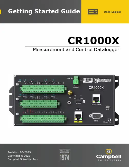
CR1000X Measurement and Control DataloggerTable of Contents1. Getting started12. USB communications23. Testing communications with EZSetup44. Making the software connection65. Creating a Short Cut data logger program86. Sending a program to the data logger127. Working with data147.1 Default data tables147.2 Collecting data157.2.1 Collecting data using LoggerNet157.2.2 Collecting data using PC400167.3 Viewing historic data161. Getting startedGetting started provides a cursory view of data acquisition and walks you through a procedure to set up a simple system. You may not find it necessary to progress beyond this. However, should you want to dig deeper into the complexity of the data logger functions or quickly look for details, extensive information is available in the full CR1000X manual.This exercise guides you through the following steps:l Connecting the data logger to a computerl Attaching a sensor to the data loggerl Creating a program for the data logger to measure the sensorl Making a simple measurementl Storing measurement data on the data loggerl Collecting data from the data logger with a computerl Viewing real-time and historical data with a computerIn addition to your data logger, the following items are used in this exercise (many are shipped with your data logger and all are available on ):l Type T thermocouple, 4 to 5 inches long; one is shipped with the data loggerl Computer with a USB portl USB cablel Data logger support software such as LoggerNet or PC400 installed on your computerAdditional Campbell Scientific publications are available online at . Video tutorials a re available at /videos . Generally, if a particular feature of the data logger requires a peripheral hardware device, more information is available in the help or manual written for that device.2. USB communicationsSetting up a USB connection is a good way to begin communicating with your data logger. Because this connection does not require configuration (like an IP address), you need only set up the communications between your computer and the data logger. Use the following instructionsor watch the Quickstart videos at https:///videos.Follow these steps to get started. These settings can be revisited using the data logger support software Edit Datalogger Setup option .1. Using data logger support software, launch the EZSetup Wizard.l LoggerNet users, click Setup, select the View menu and ensure you are in the EZ(Simplified) view, then click Add Datalogger.l PC400 users, click Add Datalogger.2. Click Next.3. Select your data logger from the list. In the Datalogger Name field, type a meaningfulname for your data logger (for example, a site identifier or project name), and click Next.4. Select the Direct Connect connection type and click Next.5. If this is the first time connecting this computer to a CR1000X via USB, click InstallUSB Driver, select your data logger, click Install, and follow the prompts to install theUSB driver.6. Plug the data logger into your computer using a USB cable. The USB connection supplies5 V power as well as a communications link, which is adequate for setup. A 12 V battery willbe needed for field deployment. If using RS-232, external power must be provided to the data logger, and a CPI/RS-232 RJ45 to DB9 cable is required to connect to the computer.7. From the COM Port list, select the COM port used for your data logger. It will appear asCR1000X (COM number).8. USB connections do not typically require a COM Port Communication Delay; this type ofdelay allows time for hardware devices to "wake up" and negotiate a communications link.Accept the default value of 00 seconds and click Next.9. You must match the PakBus address hardware settings of your data logger. A USBconnection does not require a baud rate selection, keep the default. T he default PakBus address is 1.10. Set an Extra Response Time if you have a difficult or marginal connection and you want thedata logger support software to wait a certain amount of time before returning acommunications failure error. Accept the default value of 00 seconds.11. Set a Max Time On-Line to limit the amount of time the data logger remains connected.When the data logger is connected, communications with it are terminated when this time limit is exceeded. A value of 0 in this field indicates that there is no time limit formaintaining a connection to the data logger.12. Leave the Neighbor PakBus Address as the default of 0.13. Click Next.14. By default, the data logger does not use a security code or a PakBus encryption key.Therefore, the Security Code can be set to 0, and the PakBus Encryption Key can be left blank. If either setting has been changed, enter the new code or key.15. Click Next.16. Review the Setup Summary. If you need to make changes, click Previous to return to aprevious window and change the settings.17. Setup is now complete. The EZSetup Wizard allows you to Finish, or you may click Next totest communications, set the data logger clock, and send a program to the data logger.3. Testing communications with EZSetup1. Advance to, or select, t he Communication Test step in EZ Setup. See USB communications(p. 2) for more information.2. Ensure the data logger is physically connected to the computer, select Yes to testcommunications, then click Next to initiate the test.3. With a successful connection, the Connection Time w ith the data logger is displayed in thelower-left corner of the wizard. Click Next.4. The Datalogger Clock window displays the time for both the data logger and the computer(server).l The Adjusted Server Date/Time displays the current reading of the clock for the computer running your data logger support software. If the Datalogger Date/Timeand Adjusted Server Date/Time do not match, c lick Set Datalogger Clock to set thedata logger clock to the computer clock.l Optionally, specify a positive or negative Time Zone Offset to apply when setting the data logger clock. This offset allows you to set the clock for a data logger that is in adifferent time zone than the computer (or to accommodate for changes in daylightsaving time).5. Click Next.6. The data logger ships with a default GettingStarted program. If the data logger does nothave a program, you can choose to send one by clicking Select and Send Program. C lick Next.7. LoggerNet only - Use the following instructions or watch the Scheduled/Automatic DataCollection video :l The Datalogger Table Output Files window displays the data tables available to be collected from the data logger and the output file name. By default, all data tables setup in the data logger program will be included for collection. M ake note of theOutput File Name and location. Click Next.l Check Scheduled Collection Enabled to have LoggerNet automatically collect data from the data logger on the Collection Interval entered. When the Base Date andTime are in the past, scheduled collection will begin immediately after finishing theEZSetup wizard. Do not set up a scheduled collection during this tutorial. Click Next.8. Click Finish, or you may click Next to test communications, set the data logger clock, andsend a program to the data logger.4. Making the software connectionOnce you have configured your hardware connection (see USB communications (p. 2)), your data logger and computer can communicate. Use the Connect screen to send a program, set the clock, view real-time data, and manually collect data.LoggerNet users, select the Main category and Connect on the LoggerNet toolbar, then selectthe data logger from the Stations list, then click Connect. Once connected, select a table to view in the Table Monitor.PC400 users, click Connect, then Monitor Data. When this tab is first opened for a data logger, values from the Public table are displayed. To view data from other tables, click Add , select a table or field from the list, then drag it into a cell on the Monitor Data tab.For more information, see Working with data (p. 14).See Collecting data (p. 15) for more information on copying stored data from the data logger to the computer.To disconnect, click Disconnect.For more information, s ee the Connect Window Tutorial .5. Creating a Short Cut data logger programYou must provide a program for the data logger in order for it to make measurements, store data, or control external devices. There are several ways to write a program. The simplest is to use the program generator called Short Cut. For more complex programming, CRBasic Editor is used. The program file may use the extension .CR1X, .CRB, or .DLD.Data logger programs are executed on a precise schedule termed the scan interval, based on the data logger internal clock.Measurements are first stored in temporary memory called variables in the Public table. Data stored in variables is usually overwritten each scan. Periodically, generally on a time interval, the data logger stores data in tables. The data tables are later copied to a computer using your data logger support software.Use Short Cut software to generate a program for your data logger. Short Cut is included with your data logger support software.This section guides you through programming a CR1000X data logger to measure the voltage of the data logger power supply, the internal temperature of the data logger, and a thermocouple. With minor changes, these steps can apply to other measurements. U se the following instructions or watch the Quickstart part 3 video :1. Using data logger support software, launch Short Cut.l LoggerNet users, click Program then Short Cut.l PC400 users, click Short Cut.2. Click Create New Program.3. Select CR1000X Series and click Next.4. Lists of Available Sensors and Devices and Selected Measurements Available for Output aredisplayed. Battery voltage BattV and internal temperature PTemp_C are selected bydefault. During operation, battery and temperature should be recorded at least daily to assist in monitoring system status.5. Use the Search feature or expand folders to locate your sensor or device. Double-click on asensor or measurement in the Available Sensors and Devices list to configure the device (if needed) and add it to the Selected list. For the example program, expand the Sensors and Temperature folders and double-click Type T Thermocouple.6. If the sensor or device requires configuration, a window displays with configurationoptions. Click Help at the bottom of the window to learn more about any field or option.For the example program, accept the default options:l 1 Type T TC sensorl Temp_C as the Temperature label, and set the units to Deg Cl PTemp_C as the Reference Temperature Measurement7. Click the Wiring tab at the top of the page to see how to wire the sensor to the data logger.With the power disconnected from the data logger, insert the wires as directed in thediagram. Ensure you clamp the terminal on the wire, not the colored insulation. Use the included flat-blade screwdriver to open and close the terminals.8. Click OK.9. Click Next.10. Use the Output Setup options to specify how often to make measurements and how oftenoutputs are to be stored. Type 1 in the How often should the data logger measure itssensor(s)? box. Leave the units as Seconds.11. Multiple output intervals can be specified, one for each output table (Table1 and Table2tabs). For the example program, only one table is needed. Click the Table2 tab and click Delete Table.12. In the Table Name box, type a name for the table. For example: OneMin.13. Select a Data Output Storage Interval. For example: 1 minute.14. Click Next.15. Select a measurement from the Selected Measurements Available for Output list, then clickan output processing option to add the measurement to the Selected Measurements for Output list. For the example program, select BattV and click the Minimum button to add it to the Selected Measurements for Output list. Do not store the exact time that theminimum occurred. Repeat this procedure for an Average PTemp_C and Average Temp_C.16. Click Finish and give the program a meaningful name such as a site identifier. Click Save.17. If LoggerNet or other data logger support software is running on your computer, and thedata logger is connected to the computer, you can choose to send the program. Generally it is best to collect data first; so, we recommend sending the program using the instructions in Sending a program to the data logger (p. 12). Click No, do not send the program to the data logger.18. Make note of the newly generated program location and filename. By default, programscreated with Short Cut are stored in C:\Campbellsci\SCWin\.19. Close Short Cut.If your data acquisition requirements are simple, you can probably create and maintain a data logger program exclusively with Short Cut. If your data acquisition needs are more complex, the files that Short Cut creates are a great source for programming code to start a new program or add to an existing custom program using CRBasic. See the CRBasic Editor help for detailed information on program structure, syntax, and each instruction available to the data loggerhttps:///crbasic/cr1000x/ .6. Sending a program to the data loggerSome methods of sending a program give the option to retain data when possible. Regardless of the program upload tool used, data will be erased when a new program is sent if any change occurs to one or more data table structures in the following list:l Data table name(s)l Data output interval or offset l Number of fields per record l Number of bytes per fieldl Field type, size, name, or position l Number of records in tableU se the following instructions or watch the Quickstart part 4 video .1. Connect the data logger to your computer.lLoggerNet users, select Main and Connect on the LoggerNettoolbar, select the data logger from the Stations list, then Connect.l PC400 users, select the data logger from the list and click Connect .2. LoggerNet users, click Send New... (located in the Current Program section on the right sideof the window).PC400 users, click S end Program... (located in the Datalogger Program section on the right side of the window).3. PC400 users, confirm that you would like to proceed and erase all data tables saved on thedata logger. Click Yes.4. Navigate to the program, select it, and click Open. For example: navigate toC:\Campbellsci\SCWin and select MyTemperature.CR1X. Click Open.5. LoggerNet users, confirm that you would like to proceed and erase all data tables saved onthe data logger. Click Yes.6. The program is sent and compiled.7. Review the Compile Results window for errors, messages and warnings.8. LoggerNet users, click Details, select the Table Fill Times tab.PC400 user click OK then click Station Status, select the Table Fill Times tab.Ensure that the times shown are expected for your application. Click OK.After sending a program, it is a good idea to monitor the Public table to make sure sensors are taking good measurements. See Working with data (p. 14) for more information.7. Working with data7.1 Default data tablesBy default, the data logger includes three tables: Public, Status, and DataTableInfo. Each of these tables only contains the most recent measurements and information.l The Public table is configured by the data logger program, and updated at the scan interval set within the data logger program. It shows measurement and calculation results as they are made.l The Status table includes information about the health of the data logger and is updated only when viewed.l The DataTableInfo table reports statistics related to data tables. It also only updates when viewed.l User-defined data tables update at the schedule set within the program.For information on collecting your data, see Collecting data (p. 15).Use these instructions or follow the Connect Window tutorial to monitor real-time data.LoggerNet users, select the Main category and Connect on the LoggerNet toolbar, then selectthe data logger from the Stations list, then click Connect. Once connected, select a table to view in the Table Monitor.PC400 users, click Connect, then Monitor Data. When this tab is first opened for a data logger, values from the Public table are displayed. To view data from other tables, click Add , select a table or field from the list, then drag it into a cell on the Monitor Data tab.7.2 Collecting dataThe data logger writes to data tables b ased on intervals and conditions set in the CRBasic program. After the program has been running for enough time to generate data records, data may be collected by using data logger support software. During data collection, data is copied to the computer and still remains on the data logger. Collections may be done manually, or automatically through scheduled collections set in LoggerNet Setup. Use these instruction or follow the Collect Data Tutorial .7.2.1 Collecting data using LoggerNet1. From the LoggerNet toolbar, click Main and Connect, select the data logger from theStations list, then Connect.2. Click Collect Now.3. After the data is collected, the Data Collection Results window displays the tables collectedand where they are stored on the computer.4. Select a data file, then View File to view the data. See Viewing historic data (p. 16)7.2.2 Collecting data using PC4001. Click Connect on the main PC400 window.2. Go to the Collect Data tab.3. By default, all output tables set up in the data logger program are selected for collection.Typically, the default tables (DataTableInfo, Public, and Status) are not collected.4. Select an option for What to Collect. Either option creates a new file if one does not alreadyexist.l New data from data logger (Append to data files): This is the default, and most often used option. Collect only the data, in the selected tables, stored since the last datacollection from this instance of PC400 and append this data to the end of the existingfiles on the computer.l All data from data logger (Overwrite data files): Collects all of the data in the selected tables and overwrites (or replaces) the existing data files on the computer.5. Click Start Data Collection.6. After the data is collected, the Data Collection Results window displays the tables collectedand where they are stored on the computer.7. Select a data file, then View File to view the data. See Viewing historic data (p. 16)7.3 Viewing historic dataView Pro contains tools for reviewing data in tabular form as well as several graphical layouts for visualization. Use these instructions or follow the View Data Tutorial .Once the data logger has had enough time to store multiple records collect and review the data.1. To view the most recent data, connect the data logger to your computer and collect yourdata (see Collecting data (p. 15) for more information).2. Open View Pro:l LoggerNet users click Data then View Pro on the LoggerNet toolbar.l PC400 users click View Data Files via View Pro.3. Click Open, navigate to the directory where you saved your tables (the default directoryis C:\Campbellsci\[your data logger software application]). For example: navigate to theC:\Campbellsci\LoggerNet folder and select OneMin.dat.4. Click Open.AustraliaLocation: Phone: Email: Website:Garbutt, QLD Australia 61.7.4401.7700********************.au .auBrazilLocation: Phone: Email: Website:São Paulo, SP Brazil11.3732.3399**********************.br .brCanadaLocation: Phone: Email: Website:Edmonton, AB Canada 780.454.2505************************** www.campbellsci.caChinaLocation: Phone: Email: Website:Beijing, P. R. China86.10.6561.0080********************.cn Costa RicaLocation: Phone:San Pedro, Costa Rica506.2280.1564FranceLocation:Phone:Email:Website:Montrouge, France0033.0.1.56.45.15.20*******************www.campbellsci.frGermanyLocation:Phone:Email:Website:Bremen, Germany49.0.421.460974.0*******************www.campbellsci.deIndiaLocation:Phone:Email:Website:New Delhi, DL India91.11.46500481.482*******************www.campbellsci.inSouth AfricaLocation:Phone:Email:Website:Stellenbosch, South Africa27.21.8809960********************.zawww.campbellsci.co.zaSpainLocation:Phone:Barcelona, Spain34.93.2323938ThailandLocation:Phone:Email:Website:Bangkok, Thailand66.2.719.3399*********************UKLocation:Phone:Email:Website:Shepshed, Loughborough, UK44.0.1509.601141********************.ukUSALocation:Phone:Email:Website:Logan, UT USA435.227.9120********************Campbell Scientific Regional Offices。
日光温室遮阳与喷雾降温对越夏快菜生长及品质的影响袁丁;秦占军;武占会;梁浩;李炎艳;王宝驹;王丽萍【摘要】以京研快菜为试材,设置遮阳网、遮阳网+外侧喷雾、遮阳网+内侧喷雾3种降温处理,研究不同降温方式对日光温室环境指标的影响,以及对越夏快菜生长及品质的影响.结果表明:在夏季晴朗天气,3种降温方式均能降低日光温室室内温度,其中遮阳网+内侧喷雾处理的降温效果最好;3种降温处理均能提高快菜植株的净光合速率和气孔导度,遮阳网+内侧喷雾处理的快菜株高和叶片数显著高于仅遮阳网处理及对照,增设喷雾处理的快菜单株质量显著高于仅遮阳网处理且品质更好.【期刊名称】《中国蔬菜》【年(卷),期】2019(000)007【总页数】5页(P62-66)【关键词】日光温室;遮阳;喷雾降温;越夏生产;快菜【作者】袁丁;秦占军;武占会;梁浩;李炎艳;王宝驹;王丽萍【作者单位】河北工程大学园林与生态工程学院,河北邯郸 056038;北京市农林科学院蔬菜研究中心,北京100097;北京市农林科学院蔬菜研究中心,北京100097;农业农村部华北都市农业重点实验室,北京 100097;北京市农林科学院蔬菜研究中心,北京100097;农业农村部华北都市农业重点实验室,北京 100097;河北工程大学园林与生态工程学院,河北邯郸 056038;邯郸市农业科学院,河北邯郸 056001;北京市农林科学院蔬菜研究中心,北京100097;农业农村部华北都市农业重点实验室,北京100097;河北工程大学园林与生态工程学院,河北邯郸 056038【正文语种】中文日光温室能够为蔬菜作物提供良好的生长环境,具有显著的经济效益和社会效益,但是在北京夏季中午时段,天气晴朗、阳光较好时室外温度可达40 ℃,室内温度则高达50 ℃(崔建云等,2006)。
而蔬菜作物生长的适宜温度多为20~30 ℃,温度过高会导致坐果率低下、花瓣凋零等问题,因此研究日光温室夏季降温措施、延长温室生产时间、提高温室利用率已成为热点(刘建荣等,2018)。
考古与文博研究西千佛洞位于甘肃省敦煌市西南约35公里处党河北岸的崖壁上,洞窟分布在东西长2.5公里的崖壁上,现存北魏、西魏、北周、隋、唐、五代、宋、回鹘、西夏、元代洞窟22个[1]。
1961年,西千佛洞被国务院列为第一批全国重点文物保护单位。
西千佛洞始凿于北魏,经历了1500多年自然和人为因素影响,岩体存在风化、裂隙、冲沟等问题,壁画存在起甲、脱落、酥碱、变色等多种病害。
李最雄[2]、张博[3]等研究表明,石窟岩体风化受多重因素共同作用,包括岩体自身特性和自然环境,降雨、光照、温湿度变化会引起岩体矿物质吸水膨胀、失水收缩,胶结物质老化,周期性的干湿交替使得岩体结构受损,强度降低,最终导致岩体风化。
季节性的冻融循环作用,使得岩体也出现开裂、脱落现象。
西千佛洞属典型的温带大陆性干旱气候,日照强,降水少,蒸发量大,突发性强降雨会产生地表径流,冲蚀崖壁形成冲沟,威胁洞窟文物保存[4]。
敦煌地区风沙活动研究表明,偏西风形成的强风沙流造成敦煌西千佛洞气象环境变化特征分析牟锐王小伟薛平李荣华(敦煌研究院国家古代壁画与土遗址保护工程技术研究中心,甘肃敦煌736200)[摘要]为明确西千佛洞文物的赋存环境,本研究选取了2019-2020年气象站监测数据集,分析西千佛洞各气象要素如太阳辐射、气温、相对湿度、降水、风向、风速的年、季、月、日变化特征及相互关系。
研究表明:西千佛洞太阳辐射、气温、风向、风速年际较差小,降水、相对湿度年际变化较大。
各气象要素的季、月、日波动幅度较大。
太阳辐射与气温变化趋势一致,夏季最高,冬季最低,太阳辐射年均182.7W/m2,气温年均11.9℃,温差最大54℃。
年降水低于100mm,集中在6、7月,以小雨为主。
相对湿度四季呈递增趋势,RH≥67%占比20%,相对湿度最大100%,湿差最大98%。
文物处在干湿交替、冷热大幅度变化的环境中,易引发塑像壁画粉化、起甲等病害。
区域主风向为西南风,风速小对石窟影响较小;强风集中在东北~东南(NNE~SE)方向,最大风速17.9m/s,东南方向强风对崖面产生强烈风蚀作用,东北方向强风形成的风沙流对石窟文物本体及环境危害最大。
一、基本知识1、注意:不同的转接线在接不同的USB 口时,转化出来的COM 口不同,请及时查看。
2、波特率为9600—115200,数值越大,通信速度越快,建议使用9600 比较稳定,直连的情况下可以使用115200.3、Campbell 公司的采集器是一种可编程的数据采集器****警告1、发送程序将导致数采内部存储的数据全部被清空,并且不可修复,请在发送程序前备份数采内部数据。
如果数采配置有CFM100 或者NL115 模块,配置有CF 卡的话,卡内的数据也一起清空,请在发送程序前取卡。
2、请发送数采对应的程序,CR1000 为.cr1 后缀的文件,如果发送错误,比如为.cr3 文件,将会导致数采的不可逆损坏,只能返厂修理、4、使用Custom…(自定义采集)可以更改数据的名称以及存储路径。
在第三个选项File Format 中,可以选择ASCII Table Data,Long Header,(TOACI1)(ASCII 长字头文件,TOACI1 格式),ASCII Table Data,Long Header,(TOA5)(ASCII 长字头文件,TOA5 格式),Binary Table Data (TOB1)(二进制数据文件TOB1 格式),Array Compatible CSV(EXcell 表格文件)。
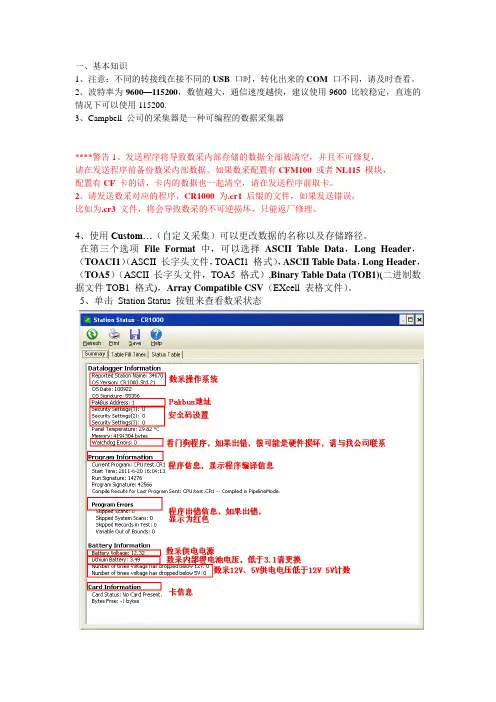
5、单击Station Status 按钮来查看数采状态二、故障诊断1、从数采采集的数据为.dat 格式,可以使用Excel 表格打开,但是很多客户在打开数据时发现数据没有分列,可以通过如下操作解决:选择某列数据,点击Excel 的数据,选择分列选项,在弹出对话框中选择,逗号分隔即可解决问题。
2、点击LoggerNet 软件主界面上的按钮CardConvert,可以转化数据。
***注意:数采内部存储的数据格式为TOB3,可以使用Cardconvert 工具将数据格式转化为TOB1,以便于Edire 软件(国际通用的处理涡动数据软件)使用,只需在数据输出的File Format 处更改为TOB1 即可。
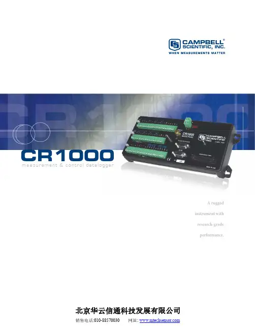
A rugged instrument with research-grade performance.m e a sur e m e nt & c ontr o l d atal o gg e rCAMPBELL®SCIENTIFIC, INC.W H E N M E A S U R E M E N T S M A T T E RCR1000北京华云信通科技发展有限公司The CR1000 provides precision measurement capabilities in a rugged, battery-operated package. It consists of a measurement and control module and a wiring panel. Standard operating range is -25° to +50°C; an optional extended range of -55° to +85°C is available.*Originally, the standard CR1000 had 2 MB of data/program storage, and an optional version, the CR1000-4M, had 4 MB of memory. In September 2007, the standard CR1000 started having 4 MB of memory, making the CR1000-4M obsolete. Dataloggers that have a module with a serial num-ber greater than or equal to 11832 will have a 4 MB memory. Th e 4 MB dataloggers will also have a sticker on the canister stating “4M Memory”.CR1000Measurement and Control SystemInput/Output Terminals —Individually configured for ratiometric resistive bridge, thermocouple, switch closure, high fre-quency pulse, low-level ac, serial sensors, and more.CS I/O Port —connects with AC-powered PCs and com-munication peripherals such as phone, RF, short-haul, and multidrop modems.RS-232—provides a 9-pin DCE port for connecting a battery-powered laptop, serialsensors or RS-232 modems.Removable Power Terminal —simplifi es connection to external power supply.Peripheral Port —allows data to be stored on a CompactFlash card and/or supports Ethernet communications.{Features4 Mbyte memory*• Program execution rate of up to 100 Hz • CS I/O and RS-232 serial ports • 13-bit analog to digital conversions• 16-bit H8S Renesas Microcontroller with 32-bit • internal CPU architectureTemperature compensated real-time clock• Background system calibration for accurate mea-• surements over time and temperature changes Single DAC used for excitation and measurements • to give ratio metric measurementsGas Discharge Tube (GDT) protected inputs• Data values stored in tables with a time stamp and • record numberBattery-backed SRAM memory and clock ensuring • data, programs, and accurate time are maintained while the CR1000 is disconnected from its main power sourceSerial communications with serial sensors and • devices supported via I/O port pairs P • akBus ®, Modbus, DNP3, TCP/IP , FTP , and SMTP protocols supportedMeasurement and Control ModuleTh e module measures sensors, drives direct communi-cations and telecommunications, reduces data, con-trols external devices, and stores data and programs in on-board, non-volatile storage. Th e electronics are RF shielded and glitch protected by the sealed, stainless steel canister. A battery-backed clock assures accurate timekeeping. Th e module can simultaneously provide measurement and communication functions. Th e on-board, BASIC-like programming language sup-ports data processing and analysis routines.Wiring PanelTh e CR1000WP is a black, anodized aluminum wiring panel that is compatible with all CR1000 modules. Th e wiring panel includes switchable 12 V , redistributed analog grounds (dispersed among analog channels rather than grouped), unpluggable terminal block for 12 V connections, gas-tube spark gaps, and 12 V sup-ply on pin 8 to power our COM-series phone modems and other peripherals. Th e control module easily dis-connects from the wiring panel allowing fi eld replace-ment without rewiring the sensors. A description of the wiring panel’s input/output channels follows.Analog InputsEight differential (16 single-ended) channels mea-sure voltage levels. Resolution on the most sensitive range is 0.67 µV.Pulse CountersTwo pulse channels can count pulses from high level(5 V square wave), switch closure, or low level AC signals. Switched Voltage ExcitationsTh ree outputs provide precision excitation voltages for resistive bridge measurements.Digital I/O PortsEight ports are provided for frequency measurements, digital control, and triggering. Th ree of these ports can also be used to measure SDM devices. Th e I/O ports can be paired as transmit and receive. Each pair has 0 to 5 V UART hardware that allows serial communica-tions with serial sensors and devices. An RS232-to-logic level converter may be required in some cases. CS I/O PortAC-powered PCs and many communication peripherals connect with the CR1000 via this port. Connection to an AC-powered PC requires either an SC32B or SC-USB interface. Th ese interfaces isolate the PC’s electrical system from the datalogger, thereby protecting against ground loops, normal static discharge, and noise.RS-232 PortThis non-isolated port is for connecting a battery-powered laptop, serial sensor, or RS-232 modem. Because of ground loop potential on some measure-ments (e.g., low level single-ended measurements), AC-powered PCs should use the CS I/O port instead of the RS-232 port (see above).Peripheral PortOne 40-pin port interfaces with the NL115 Ethernet Interface & CompactFlash Module, the NL120 Ether-net Interface, or the CFM100 CompactFlash® Module. Switched 12 VoltTh is terminal provides unregulated 12 V that can be switched on and off under program control. Storage CapacityTh e CR1000 has 2 MB of fl ash memory for the Operat-ing System, and 4 MB of battery-backed SRAM for CPU usage, program storage, and data storage. Data is stored in a table format. Th e storage capacity of the CR1000 can be increased by using a CompactFlash munication ProtocolsTh e CR1000 supports the PakBus, Modbus, DNP3, TCP/IP, FTP, and SMTP communication protocols. With the PakBus protocol, networks have the distrib-uted routing intelligence to continually evaluate links. Continually evaluating links optimizes delivery times and, in the case of delivery failure, allows automatic switch over to a confi gured backup route.Th e Modbus RTU protocol supports both fl oating point and long formats. Th e datalogger can act as a slave and/or master.Th e DNP3 protocol supports only long data formats. Th e dataloggers are level 2 slave compliant, with some of the operations found in a level 3 implementation.Th e TCP/IP, FTP, and SMTP protocols provide TCP/IP functionality when the CR1000 is used in conjunction with an NL115, NL120, or third party serial IP device. Refer to the CR1000 manual for more information. Power SuppliesAny 12 Vdc source can power the CR1000; a PS100 or BPALK is typically used. Th e PS100 provides a 7-Ahr sealed rechargeable battery that should be connected to a charging source (either a wall charger or solar panel). Th e BPALK consists of eight non-rechargeable D-cell alkaline batteries with a 7.5-Ahr rating at 20°C.Also available are the BP12 and BP24 battery packs, which provide nominal ratings of 12 and 24 Ahrs, respectively. Th ese batteries should be connected to a regulated charging source (e.g., a CH100 connected to a unregulated solar panel or wall charger). Enclosure/Stack BracketA CR1000 housed in a weather-resistant enclosure can collect data under extremely harsh conditions. Th e 17565 Stack Bracket allows a small peripheral to be placed under the mounting bracket, thus conserving space. With the bracket, the CR1000 can be attached in a “horizontal” orientation in an ENC10/12 enclosure (i.e., the long axis of the CR1000 spanning the short axis of the enclosure).Above is a CR1000 mounted to the stack bracket. The Velcro strap is for fastening a peripheral to the base of the bracket.Keyboard DisplayTh e CR1000KD can be used to program the CR1000, manually initiate data transfer, and display data. Th e CR1000KD displays 8 lines x 21 characters (64 x 128 pixels) and has a 16-character keyboard. Custommenus are supported allow-ing customers to set up choiceswithin the datalogger programthat can be initiated by a simple“toggle” or “pick list”.Portable Handheld DevicesAn Archer-PCon or user-supplied PDA can be used to collect and display the CR1000’s data, transfer datalog-ger programs, graph data for up to two elements, and transfer the datalogger’s data to a PC. User-supplied PDAs require either PConnect or PConnectCE soft ware. Direct LinksAC-powered PCs connect with the datalogger’s CS I/O port via an SC32B or SC-USB interface. Th ese inter-faces provide optical isolation. A battery-powered lap-top can be attached to the CR1000’s RS-232 port via an RS-232 cable—no interface required.External Data Storage DevicesA CFM100 or NL115 module can store the CR1000’s data on an industrial-grade CompactFlash (CF) card (2 GB or less). Th e PC reads the CF card using either the CF1 CompactFlash Adapter or a 17752 USB Reader/Writer. Th e CR1000 can also store data on an SC115 2-GB Flash Memory Drive. Th is light-weight device can easily be carried to the PC for data download.CD295 DataView II DisplayTh is two-line, 32-character LCD displays one real-time value, a description, and units. It is typically mounted in an enclosure lid, which allows customers to view the CR1000’s data on-site without opening the enclosure. Short Haul ModemsTh e SRM-5A RAD Short Haul Modem supports com-munications between the CR1000 and a PC via a four-wire unconditioned line (two twisted pairs). Multidrop InterfaceTh e MD485 intelligent RS-485 interface permits aPC to address and communicate with one or more dataloggers over the CABLE3CBL cable. Distancesup to 4000 feet are supported.EthernetUse of an NL120, NL115, or NL100 interface enables the CR1000 to communicate over a local network or a dedicated Internet connection via TCP/IP. Th e NL115 can also store data on a CompactFlash card.RadiosRadio frequency (RF) communications are supported via narrow-band UHF, narrow-band VHF, spread spectrum, or meteor burst radios. Line-of-sight is required for all of our RF options.Telephone NetworksTh e CR1000 can communicate with a PC using land-lines, cellular CDMA, or cellular GPRS transceivers.A voice synthesized modem enables anyone to call the CR1000 via phone and receive a verbal report of real-time site conditions.Satellite TransmittersOur NESDIS-certifi ed GOES satellite transmitter pro-vides one-way communications from a Data Collection Platform (DCP) to a receiving station. We also off er an Argos transmitter that is ideal for high-altitude and polar applications and a METEOSAT transmitter for European applications.Data Storage and Retrieval OptionsTo determine the best option for an application, consider the accessibility of the site, availability of services (e.g., cellular phone or satellite coverage), quantity of data to collect, and desired time between data-collection sessions. Some communication options can be combined—increasing the fl exibility, convenience, and reliability of the communications.One CR1000KD can becarried from station to sta-tion in a CR1000 network.This weather station at Denali National Park, Alaska, transmits datavia a GOES satellite transmitter.Channel Expansion4-Channel Low Level AC ModuleTh e LLAC4 is a small peripheral device that allows customers to increase the number of available low-level ac inputs by using control ports. Th is module is oft en used to measure up to four anemometers, and is especially useful for wind profi ling applications. Synchronous Devices for Measurement (SDMs) SDMs are addressable peripherals that expand the data-logger’s measurement and control capabilities. For example, SDMs are available to add control ports, analog outputs, pulse count channels, interval timers, or even a CANbus interface to the system. Multiple SDMs, in any combination, can be connected to one datalogger. MultiplexersMultiplexers increase the number of sensors that can be measured by a CR1000 by sequentially connecting each sensor to the datalogger. Several multiplexers can be controlled by a single CR1000.SoftwareStarter Soft wareOur easy-to-use starter soft ware is intended for fi rst time users or applications that don’t require sophisti-cated communications or datalogger program editing. SCWin Short Cut generates straight-forward CR1000 programs in four easy steps. PC200W allows custom-ers to transfer a program to, or retrieve data from a CR1000 via a direct communications link.At /downloads you can down-load starter soft ware at no charge. Our Resource CD also provides this soft ware as well as PDF versions of our brochures and manuals.Datalogger Support Soft wareOur datalogger support soft ware packages provide more capabilities than our starter soft ware. Th ese soft ware packages contains program editing, commu-nications, and display tools that can support an entire datalogger network.PC400, our mid-level soft ware, supports a variety of telemetry options, manual data collection, and data display. For programming, it includes both Short Cut and the CRBasic program editor. PC400 does not support combined communication options (e.g., phone-to-RF), PakBus® routing, or scheduled data collection.RTDAQ is an ideal solution for industrial and real-time users desiring to use reliable data collectionsoft ware over a single telecommunications medium, and who do not rely on scheduled data collection. RTDAQ’s strength lies in its ability to handle the display of high speed data.LoggerNet is Campbell Scientifi c’s full-featured datalog-ger support soft ware. It is referred to as “full-featured” because it provides a way to accomplish almost all the tasks you’ll need to complete when using a datalogger. LoggerNet supports combined communication options(e.g., phone-to-RF) and scheduled data collection.The Network Planner, included in LoggerNet 4 or higher, gener-ates device settings and confi gures the LoggerNet network mapfor PakBus networks.Both LoggerNet and RTDAQ use View Pro to display historical data in a tabular or graphical format.The CR1000 is compatible with the AM16/32B (shown above) and AM25T multiplexers.ApplicationsThe measurement precision, fl exibility, long-term reliability, and economical price of the CR1000 make it ideal for scientifi c, commercial, and industrial applications.MeteorologyTh e CR1000 is used in long-term climatological moni-toring, meteorological research, and routine weather measurement applications.Sensors the CR1000 can measure include: Agriculture and Agricultural ResearchTh e versatility of the CR1000allows measurement of agricul-tural processes and equipmentin applications such as:plant water research•canopy energy balance•machinery performance•plant pathology•crop management•decisionsfood processing/storage•frost prediction•irrigation scheduling•integrated pest•management Wind ProfilingOur data acquisition systems can monitor conditionsat wind assessment sites, at producing wind farms,and along transmission lines. Th e CR1000 makes andrecords measurements, controls electrical devices, andcan function as PLCs or RTUs. Because the datalog-ger has its own power supply (batteries, solar panels),it can continue to measure and store data and performcontrol during power outages.Typical sensors for wind assessment applications in-clude, but are not limited to:s onic anemometers•t hree-cup and propeller•anemometers (up to10 anemometers can bemeasured by using twoLLAC4 peripherals)wind vanes•temperature sensors•barometric pressure•wetness•solar radiation•For turbine performanceapplications, the CR1000monitors electrical current,voltage, wattage, stress, and torque.Soil MoistureTh e CR1000 is compatible with the following soilmoisture measurement technologies:Soil moisture blocks are inexpensive sensors•that estimate soil water potential.Matric water potential sensors also estimate•soil water potential but are more durable thansoil moisture blocks.Time-Domain Refl ectometry Systems (TDR)•use a refl ectometer controlled by a CR1000 toaccurately measure soil water content. Multi-plexers allow sequential measurement of a largenumber of probes by one refl ectometer, reducingcost per measurement.Self-contained water content refl ectometers are•sensors that emit and measure a TDR pulse.Tensiometers measure the soil pore pressure of•irrigated soils and calculate soil moisture.Our rugged, reliable weather station measures meteorologicalconditions at St. Mary’s Lake, Glacier National Park, MT.cup, propeller, and•sonic anemometerstipping bucket•rain gageswind vanes•pyranometers•ultrasonic ranging•sensorthermistors, RTDs,•and thermocouplesbarometric pressure•sensorsRH sensors•cooled mirror•hygrometersThis vitaculture site inAustralia integrates meteo-rological, soil, and cropmeasurements.A Campbell Scientific systemmonitors an offshore windfarm in North Wales.Photo courtesy npower renewablesCopyright © 2004, 2010Campbell Scienti fi c, Inc. Campbell Scientific, Inc. | 815 W 1800 N | Logan, Utah 84321-1784 | (435) 753-2342 | 。
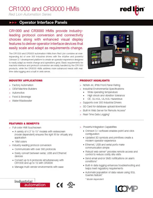
CR1000 and CR3000 HMIsRed Lion Automation SeriesPRODUCT HIGHLIGHTS>NEMA 4X, IP66 Front Panel Rating >Industrial Environmental Specifications •Wide operating temperature•High shock and vibration tolerance •CE, UL/cUL, UL/cUL Hazardous >Supports over 300 Industrial Drivers >SD Card for database upload/download >Built-In Web Server for Remote Access* >Real-Time Data Logging*CR1000 and CR3000 HMIs provide industry-leading protocol conversion and connectivity choices along w ith enhanced visual display features to deliver operator interface devices that easily scale and adapt as requirements change.The CR1000 and CR3000 automation HMIs from Red Lion combine an ever-expanding list of over 300 industrial drivers with the intuitive and powerful Crimson 3.1 development platform to create an operator experience designed to easily adapt as needs change and operations grow. Basic requirements for machine interface and protocol conversion are easily handled by the CR1000 products, while the CR3000 HMIs address more advanced needs with real-time data logging and a built-in web server.INDUSTRY APPLICATIONS >Factory Automation >OEM Machine Builders >Automotive >Food & Beverage >Water/WastewaterCUSU LFEATURES & BENEFITS > F ull-color HMI touchscreen•A variety of 4.3” to 15” models with widescreen(model dependent) ensures the right fit for virtually any application •16M colors>Industry-leading protocol conversion • C ommunicate with over 300 protocols• E asily convert between serial, USB and Ethernet devices•Convert up to 6 protocols simultaneously with CR1000 and up to 15 with CR3000•Manage multi-vendor environments with ease>Powerful Integration Capabilities• C rimson 3.1 software enables point-and-click configuration• U pdated 3D symbols and primitives create a modern operator experience •Ethernet, USB and serial ports make communication simple• R obust web server* provides remote access and control to reduce costly site visits•Send email and/or SMS notifications on alarm conditions*•Built-in data logging enhances troubleshooting and helps meet regulatory requirements•Automate population of data values using SQL Queries feature**Model dependentCOMMUNICATION PROPERTIESUSB PortsUSB Device:CR1000 and CR3000 (All Models) - (1) USB DeviceT ype B adheres to USB specification 1.1USB Host:CR3000 (4.3”) – (1) USB Host portCR3000 (7”, 10.4”, 15”) – (2) USB Host portsType A adheres to USB specification 2.0 and supports full-speeddata transfers with hardware overcurrent protected (0.5 A max perport)Serial Ports for programming or communications: Format/Baud ratesindependently configurableCR1000 (All) - One (1) RS232 and One (1) RS232/RS422/RS485selectableCR3000 (4.3”) - Two (2) RS232 and One (1) RS422/RS485CR3000 (7”, 10.4”, 15”) - Two (2) RS232 and Two (2) RS422/RS485 Ethernet Ports: 1500 Vrms network isolationCR1000 (All) - One (1) 10/100 BASE-T(X) port (RJ45)CR3000 (4.3”) - One (1) 10/100 BASE-T(X) port (RJ45)CR3000 (7”, 10.4”, 15”) - Two (2) 10/100 BASE-T(X) ports (RJ45) POWER INPUTCR1000 (All models) 24 VDC +/- 20%CR3000 (All models) 10 to 30 VDCMust use a Class 2 circuit according to National Electrical Code (NEC),NFPA-70 or Canadian Electrical Code (CEC), Part I, C22.1 or a Limited Power Supply (LPS) according to IEC 60950-1 or Limited-energy circuit according to IEC 61010-1. Power connection via removable threeposition terminal block.Battery: Lithium coin cellTypical lifetime of 5 yearsPOWER CONNECTIONHigh compression cage-clamp terminal blockWire Strip Length: 0.3” (7.5 mm)Wire Gauge Capacity: 12 to 24 AWG (3.31 to 0.20 mm2) copper wire Torque: 4.4-5.3 inch-lbs (0.5-0.6 N-m)NETWORK MEDIA10BaseT: ≥ Cat3 cable100BaseTX: ≥ Cat5 cableENVIRONMENTALOperating Temperature: -10°C to 50°CStorage Temperature: -20°C to 70°COperating Humidity: 0 to 85% (non condensing)Operating Altitude: Up to 2000 metersShock: 30 g per IEC 68-2-27Vibration: 2 g @ 5-500 Hz per IEC 68-2-6CERTIFICATION & COMPLIANCECE ApprovedImmunity: IEC/EN 61000-6-2 for Industrial LocationsEmissions: IEC/EN 6100-6-4 for Industrial Locations; CISPR 11 Class A Safety: IEC/EN 61010-1RoHS CompliantUL ListedClass I, Division 2, Groups A, B, C and D for CR3000 onlyType 4X Indoor / IP66 Enclosure rating (front face only) MECHANICALConstruction: Polycarbonate enclosure with NEMA 4X/IP66 rating forindoor use when correctly fitted with the gasket provided. Installation Category II, Pollution Degree 2.Weight:CR1000 4.3” model – 15.0 oz (425 g)CR1000 7” model – 1.91 lb (868 g)CR1000 10.4” model – 3.08 lb (1.395 Kg)CR3000 4.3” model – 1.00 lb (454 g)CR3000 7” model – 2.01 lb (913 g)CR3000 10.4” model – 3.16 lb (1.435 Kg)CR3000 15” model – 4.12 lb (2.155 Kg)Specifications are subject to change. Visit for more information.Dashes in listed model numbers added to improve readability, and are not included in orderable part numbers. CR1000 and CR3000 HMIs Ordering Guide4.3” models7” Models10” ModelsTHIS VIEW SHOWN WITH MOUNTING PLATE AND BRACKETSTHIS VIEW SHOWN WITH MOUNTING PLATE AND BRACKETSConnect. Monitor. Control.ADLD0478 042718 © 2018 Red Lion Controls, Inc. All rights reserved. Red Lion, the Red Lion logo, N-Tron and Sixnet are registered trademarks of Red Lion Controls, Inc. All other company and product names are trademarks of their respective owners.As the global experts in communication, monitoring and control for industrial automation and networking, Red Lion has been delivering innovative solutions for over forty years. Our automation, Ethernet and cellular M2M technology enables companies worldwide to gain real-time data visibility that drives productivity. Product brands include Red Lion, N-Tron and Sixnet. With headquarters in York, Pennsylvania, the company has offices across the Americas, Asia-Pacific and Europe. Red Lion is part of Spectris plc, the productivity-enhancing instrumentation and controls company. For more information, please visit .THIS VIEW SHOWN WITH MOUNTING PLATE AND BRACKETSTHIS VIEW SHOWN WITH MOUNTING PLATE AND BRACKETS4.3” models7” Models10” Models。
一、概述自动气象站采用的LoggerNet软件是Campbell 公司开发的一种集通讯和数据采集于一体的应用软件,运行在Windows95,98,Windows NT 4.0、Windows 2000或Windows XP环境下的应用软件。
用户可通过该软件进行配置,建立PC机和数据采集器的连接,发送采集程序,收集数据,观察实时数据,以及进行数据分析等。
LoggerNet的最新版本为3.1.5。
安装软件时。
建议LoggerNet的运行路径和工作路径安装在不同的磁盘分区上,工作路径最好不要安装在计算机的操作系统所在的磁盘上,因为LoggerNet默认的收集数据的路径在其工作路径所在的磁盘上。
当然,下载数据时,用户可以选择不同的路径存放文件。
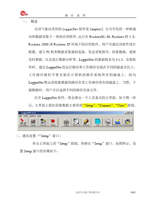
打开LoggerNet软件,将会弹出一个工具条式的主界面,如下图一所示。
主界面上我们采集数据主要用到“Setup”、“Connect”、“View”按钮。
二、通讯设置(“Setup”窗口)单击主界面上的“Setup”按钮,将弹出“Setup”窗口,如图所示。
设置Setup窗口的步骤如下:2.1.1点击“AddRoot”按钮,弹出Add窗口2.1.2选择添加“ComPort”,弹出此时选择PakBusPort(Other Logger)选项弹出选择CR1000选项然后点击Close按钮,Setup窗口变为点击Setup窗口下面的Apply按钮,再在窗口左侧的导航栏里选择CR1000,单击窗口右面的“Data Files”标签页,出现如图所示的画面。
将CR1000与电脑连接好再点击标签页下面的Get Table Definitions按钮得到采集器的数据表定义。
再在标签页左边数据表栏中选择数据表(注:数据表名在编写程序里命名)此时在标签页的“Output File Name”下面的文本框显示为采集数据路径和名,其路径和名可以更改,点击文本框右面的按钮,在弹出的Windows“另存为”对话框内选择存储路径和文件名。

系统安装调试报告(超声波测风)项目名称:项目地址:项目实施人:项目实施日期:年月日项目简介风场址号拟安装日期年月日风场地址塔厂址名称纬度盛行风向经度地形类型海拔高度塔高项目实施人签字:签字时间:系统简介系统名称:系统主要施工内容:项目开工日期:年月日项目拟完成日期:年月日系统设备清单及配件清点记录序号设备名称合同数量实际到货数量零配件全否备注1风塔2 普通测风系统3 工控机KVM4 超声测风系统5 规约转换6 无线传输模块7 服务器8 pc机9 防火墙10 反向隔离11 机柜注:1、实际到货与合同型号或数量不符,请在备注中说明原因;2、设备随机清单、合格证、保修卡、安装手册等如不齐全,请在备注中说明缺少什么3、设备随机零配件不全请在表中说明项目开工组织以下事项是否齐备,请做选择,如不满足,请在备注中说明:☐项目管理实施规划(施工组织设计)已审批;☐施工图会检已进行;☐各项施工管理制度和相应的作业指导书已制定并审查合格;☐安全文明施工二次策划满足要求;☐施工技术交底已进行;☐施工人力和机械已进场,施工组织已落实到位;☐物资、材料准备能满足连续施工的需要;☐计量器具、仪表经法定单位检验合格;☐特殊工种作业人员能满足施工需要。
备注:如全部满足,请签字确认,并进行项目施工项目实施人签字:签字日期:年月日第一部分:测风塔的安装(本项目如果不包含测风塔,本部分可以不填写)测风塔塔架出厂资料测风塔制造商:产品出厂合格证标示工程名称:基站名称:产品名称:测风通讯塔规格型号:M数量:一座出厂编号:本产品符合标准:GB/T2694-2003《输电线路铁塔制造技术条件》DL/T646-1998《钢管杆塔制造技术条件》YDT/757-1995《微波通信铁塔制造技术条件》GY65-1989《广播电视塔制造技术条件》GB50205-2001《钢结构工程施工及验收》铁塔出厂检验记录工程名称规格型号M样品基数1基产品标准YD/T5132-2005 检验标准YD/T5132-2005 报告编号材质配件目次检验项目名称标准要求允许偏差实测结果实测偏差结论一材料符合标准和实际要求二装配1 端距±5.02 通信孔距与构件中心相对偏差±1.03连接间隙变宽50MM以下≤1.04 变宽50MM以上≤2.05 接头装配尺寸位移有孔≤1.06 无孔≤5.0三试装1 试装就位率≥99%2 通心孔率≥96%3 试装控制尺寸正常结论按YD/T5132-2005标准试装并检验所有项目符合设计要求,检验合格。
一、概述自动气象站采用的LoggerNet软件是Campbell 公司开发的一种集通讯和数据采集于一体的应用软件,运行在Windows95,98,Windows NT 4.0、Windows 2000或Windows XP环境下的应用软件。
用户可通过该软件进行配置,建立PC机和数据采集器的连接,发送采集程序,收集数据,观察实时数据,以及进行数据分析等。
LoggerNet的最新版本为3.1.5。
安装软件时。
建议LoggerNet的运行路径和工作路径安装在不同的磁盘分区上,工作路径最好不要安装在计算机的操作系统所在的磁盘上,因为LoggerNet默认的收集数据的路径在其工作路径所在的磁盘上。
当然,下载数据时,用户可以选择不同的路径存放文件。
打开LoggerNet软件,将会弹出一个工具条式的主界面,如下图一所示。
主界面上我们采集数据主要用到“Setup”、“Connect”、“View”按钮。
二、通讯设置(“Setup”窗口)单击主界面上的“Setup”按钮,将弹出“Setup”窗口,如图所示。
设置Setup窗口的步骤如下:2.1.1点击“AddRoot”按钮,弹出Add窗口2.1.2选择添加“ComPort”,弹出此时选择PakBusPort(Other Logger)选项弹出选择CR1000选项然后点击Close按钮,Setup窗口变为点击Setup窗口下面的Apply按钮,再在窗口左侧的导航栏里选择CR1000,单击窗口右面的“Data Files”标签页,出现如图所示的画面。
将CR1000与电脑连接好再点击标签页下面的Get Table Definitions按钮得到采集器的数据表定义。
再在标签页左边数据表栏中选择数据表(注:数据表名在编写程序里命名)此时在标签页的“Output File Name”下面的文本框显示为采集数据路径和名,其路径和名可以更改,点击文本框右面的按钮,在弹出的Windows“另存为”对话框内选择存储路径和文件名。
基于TDR监测技术的自然崩落法顶板崩落高度测量彭张;袁本胜;冯兴隆;王平;刘华武;蔡永顺【摘要】为制订合理的自然崩落法开采放矿策略,必须掌握自然崩落法开采过程中的崩落高度.利用TDR测量传输线的特征阻抗,定位断点或短路点具体位置的特性,通过实验室测试不同测量传输线型号、长度、温度等不同情况下在拉断过程的测量结果,寻找适合矿山传输线参数,并在普朗铜矿进行工程应用,结果证实TDR在测量自然崩落法崩落高度测量中的可行性.【期刊名称】《现代矿业》【年(卷),期】2018(000)008【总页数】4页(P86-88,112)【关键词】自然崩落法;TDR;崩落高度【作者】彭张;袁本胜;冯兴隆;王平;刘华武;蔡永顺【作者单位】云南迪庆有色金属有限责任公司;北京矿冶科技集团有限公司;金属矿山智能开采技术北京市重点实验室;云南迪庆有色金属有限责任公司;北京矿冶科技集团有限公司;金属矿山智能开采技术北京市重点实验室;云南迪庆有色金属有限责任公司;北京矿冶科技集团有限公司;金属矿山智能开采技术北京市重点实验室【正文语种】中文普朗铜矿一期采选工程设计采用自然崩落法回采,在回采过程中,矿体在崩透地表之前,相当于在空场条件下放矿,如果放矿速度过快,将可能使崩落顶板与存窿面之间留有较大的空间,一旦上部矿岩突然大范围崩落,极有可能产生空气冲击波,对坑内人员、设备和底部结构产生巨大影响[1-2]。
因此,需要掌握自然崩落法开采过程中的崩落高度,为制订合理的放矿策略提供依据。
而常规的位移计、视频摄像头甚至非接触式的三维激光扫描仪等均无法进入崩落空区使用,所以寻求在地表通过钻孔安装TDR同轴线缆的方式测量崩落高度。
1 TDR监测概述TDR仪器不仅可以用来测量传输线的特征阻抗,还可以帮助定位断点或短路点的具体位置,利用这一特性,TDR时域反射计可用于检测岩土体内的变形或破断。
在待监测的矿岩中钻孔,将同轴电缆放置于钻孔中,顶端与TDR测试仪相连,并以砂浆或树脂等方式填充电缆与钻孔之间的空隙,以保证同轴电缆与岩土体的同步变形。
神华CCS项目大气监测系统及监测分析文虎;樊贵县;翟小伟;赵兴雷;马瑞;翁力【摘要】为缓解目前CO2浓度升高导致的温室效应等环境问题,神华集团于2011年开启了每年10万吨的CCS(CO2的捕集与封存)项目,为防止封存的CO2逃逸到大气中,对封存区地表大气CO2浓度和CO2通量主要采取涡度相关系统进行监测.介绍了涡度相关技术的基础理论,分析了该技术应用在CCS项目中的初期监测结果,并对目前导致封存区地表CO2通量异常的原因进行了预测和分析.结果表明:导致封存区CO2通量异常的主要原因是CO2封存区缓冲罐的自然排放,并根据初步分析对后续的监测提出了合理的建议.【期刊名称】《安全与环境工程》【年(卷),期】2015(022)005【总页数】6页(P73-78)【关键词】涡度相关法;CO2的捕集与封存(CCS);大气监测;CO2通量【作者】文虎;樊贵县;翟小伟;赵兴雷;马瑞;翁力【作者单位】西安科技大学能源学院,陕西西安710054;西部矿井开采及灾害防治教育部重点实验室,陕西西安710054;西安科技大学能源学院,陕西西安710054;西部矿井开采及灾害防治教育部重点实验室,陕西西安710054;西安科技大学能源学院,陕西西安710054;西部矿井开采及灾害防治教育部重点实验室,陕西西安710054;北京低碳清洁能源研究所,北京102200;北京低碳清洁能源研究所,北京102200;北京低碳清洁能源研究所,北京102200【正文语种】中文【中图分类】X84近年来,由于CO2大规模的排放而引起的温室效应日益严重,对CO2的捕集与封存(CCS)成为人们关注的焦点。
我国也相继开展了CO2的捕集和资源化利用的研究,神华集团于2011年在内蒙古鄂尔多斯启动了每年10万吨的CO2深部咸水层封存项目[1]。
对于这一新技术,除有政治、政策问题及经济可行性考虑外,还存在许多技术以及政府和公众的接受性问题[2]。
其中焦点之一是能否保证CO2的安全永久埋存,这也是目前众多示范工程的主要目的。
A rugged instrument with research-grade performance.m e a sur e m e nt & c ontr o l d atal o gg e rCAMPBELL®SCIENTIFIC, INC.W H E N M E A S U R E M E N T S M A T T E RCR10002Features• 4 Mbyte memory*• Program execution rate of up to 100 Hz • CS I/O and RS-232 serial ports • 13-bit analog to digital conversions• 16-bit H8S Renesas Microcontroller with 32-bit internal CPU architecture • Temperature compensated real-time clock • Background system calibration for accurate mea- surements over time and temperature changes • Single DAC used for excitation and measurements to give ratio metric measurements• Gas Discharge Tube (GDT) protected inputs • Data values stored in tables with a time stamp and record number • Battery-backed SRAM memory and clock ensuring data, programs, and accurate time are maintained while the CR1000 is disconnected from its main power source • Measures intelligent serial sensors without using an SDM -SIO4Measurement and Control ModuleTh e module measures sensors, drives direct communi-cations and telecommunications, reduces data, con-trols external devices, and stores data and programs inon-board, non-volatile storage. Th e electronics are RF shielded and glitch protected by the sealed, stainless steel canister. A battery-backed clock assures accurate timekeeping. Th e module can simultaneously provide measurement and communication functions. Th e on-board, BASIC-like programming language sup-ports data processing and analysis routines.Wiring PanelTh e CR1000WP is a black, anodized aluminum wiring panel that is compatible with all CR1000 modules. Th e wiring panel includes switchable 12 V , redistributed analog grounds (dispersed among analog channels rather than grouped), unpluggable terminal block for 12 V connections, gas-tube spark gaps, and 12 V sup-ply on pin 8 to power our COM-series phone modems and other peripherals. Th e control module easily dis-connects from the wiring panel allowing fi eld replace-ment without rewiring the sensors. A description of the wiring panel’s input/output channels follows.CR1000Measurement & Control SystemThe CR1000 provides precision measurement capabilities in a rugged, battery-operated package. It consists of a measurement and control module and a wiring panel. Standard operating range is -25° to +50°C; an optional extended range of -55° to +85°C is available.{Removable Power Terminal —simplifi es connection to exter-nal power supply.Input/Output Connections —Individually confi gured for ratiometric resistive bridge, thermocouple, switch clo-sure, high frequency pulse, low-level ac, serial sensors, and more.Peripheral Port —one 40-pin port interfaces with a CFM100 or NL115 module, which store data on a CompactFlash card. The NL115 also supports Ethernet communications.CS I/O Port —connects with AC-powered PCs and communication peripherals such as phone, RF, short-haul, and multidrop modems.RS-232—provides a 9-pin DCE port for connecting a battery-powered laptop, se-rial sensors or RS-232 modems.*Originally, the standard CR1000 had 2 Mbytes of data/program storage, and an optional version, the CR1000-4M, had 4 Mbytes of memory. In September 2007, the standard CR1000 started having 4 Mbytes of memory, making the CR1000-4M obsolete. Dataloggers that have a mod-ule with a serial number greater than or equal to 11832 will have a 4 Mbyte memory. Th e 4 Mbyte dataloggers will also have a sticker on the canister stating “4M Memory”.Analog InputsEight diff erential (16 single-ended) channels measure voltage levels. Resolution on the most sensitive range is 0.67 µV.Pulse CountersTwo pulse channels can count pulses from high level (5 V square wave), switch closure, or low level AC signals. Switched Voltage ExcitationsTh ree outputs provide precision excitation voltages for resistive bridge measurements.Digital I/O PortsEight ports are provided for frequency measurements, digital control, and triggering. Th ree of these ports can also be used to measure SDM devices. Th e I/O ports can be paired as transmit and receive for measuring smart serial sensors.CS I/O PortAC-powered PCs and many communication peripherals connect with the CR1000 via this port. Connection to an AC-powered PC requires either an SC32B or SC-USB interface. Th ese interfaces isolate the PC’s electrical system from the datalogger, thereby protecting against ground loops, normal static discharge, and noise.RS-232 PortThis non-isolated port is for connecting a battery-powered laptop, serial sensor, or RS-232 modem. Because of ground loop potential on some measure-ments (e.g., low level single-ended measurements), AC-powered PCs should use the CS I/O port instead of the RS-232 port (see above).Peripheral PortOne 40-pin port interfaces with the CFM100 Compact-Flash® Module or the NL115 Ethernet Interface and CompactFlash Module.Switched 12 VoltTh is terminal provides unregulated 12 V that can be switched on and off under program control.Power SuppliesAny 12 Vdc source can power the CR1000; a PS100 or BPALK is typically used. Th e PS100 provides a 7-Ahr sealed rechargeable battery that should be connected to a charging source (either a wall charger or solar panel). Th e BPALK consists of eight non-rechargeable D-cell alkaline batteries with a 7.5-Ahr rating at 20°C.Also available are the BP12 and BP24 battery packs, which provide nominal ratings of 12 and 24 Ahrs, respectively. Th ese batteries should be connected to a regulated charging source (e.g., a CH100 connected to a unregulated solar panel or wall charger). For infor-mation about analyzing the system’s power require-ments, see our Power Supply product literature or Application Note 5-F. Both can be obtained from: www. Storage CapacityTh e CR1000 has 2 Mbyte of FLASH memory for the Operating System, and 4 Mbytes of battery-backed SRAM for CPU usage, program storage, and data storage. Data is stored in a table format. Th e storage capacity of the CR1000 can be increased by using a CompactFlash card.Enclosure/Stack BracketA CR1000 housed in a weather-resistant enclosurecan collect data under extremely harsh conditions. Th e enclosure protects the CR1000 from dust, water, sun-light, or pollutants. An internal mounting plateis prepunched for easy system confi guration and exchange of equipment in the fi eld.Th e 17565 Stack Bracket allows a small peripheral to be placed under the mounting bracket, thus conserving space. With the bracket, the CR1000 can be attachedin a “horizontal” orientation (i.e., the long axis of the CR1000 spanning the short axis of the ENC10/12 enclosure). Th is stack bracket also places the terminals on the wiring panel at about the same height as the terminals on a PS100.Communication ProtocolsTh e CR1000 supports the PakBus® communication protocol. PakBus networks have the distributed routing intelligence to continually evaluate links. Continually evaluating links optimizes delivery times and, in the case of delivery failure, allows automatic switch overto a confi gured backup route.Th e CR1000 also supports Modbus RTU protocol—both fl oating point and long formats. Th e datalogger can act as a slave, master, or both.The stackbracket asviewed fromthe side witha CR1000attached.34RadiosTelephone Networks Th e CR1000 can communicate with a PC using land-lines, cellular CDMA, or cellular GPRS/EDGE trans-ceivers. A voice synthesized modem enables anyone to call the CR1000 via phone and receive a verbal report of real-time site conditions.Multidrop Interface Th e MD485 intelligent RS-485 interface permits a PC to address and communicate with one or more dataloggers over a single two-twisted-pair cable. Distances up to 4000 feet are supported.Short Haul Modems Th e SRM-5A RAD Short Haul Modem supports com-munications between the CR1000 and a PC via a four-wire unconditioned line (two twisted pairs).Direct LinksAC-powered PCs connect with the datalogger’s CS I/O port via an SC32B or SC-USB interface. Th ese inter-faces provide optical isolation. A battery-powered lap-top can be attached to the CR1000’s RS-232 port via an RS-232 cable; no interface required.Keyboard Display Th e CR1000KD can be used to program the CR1000, manually initiate data transfer, and display data. Th e CR1000KD displays 8 lines x 21 characters (64 x 128 pixels) and has a 16-character keyboard. Custom menus are supported allowing customers to set up choices within the datalogger program that can be initiated by a simple “toggle” or “pick list”.EthernetUse of an NL100 or NL115 interface enables the CR1000 to communicate over a local network or a dedicated Internet connection via TCP/IP . Th e NL115 also supports data storage on a CompactFlash card.CD295 DataView II Display Th is two-line, 32-character LCD displays one real-time value, a description, and units. It is typically mounted in an enclosure lid, which allows customers to view the CR1000’s data on-site without opening the pactFlash®A CFM100 or NL115 module attached to a CR1000 can store data on a CompactFlash (CF) card. Th e PC reads the CF card using either the CF1 CompactFlash Adapter or an ImageMate® Reader/Writer. Please note that the CF card should be industrial-grade with a storage capacity of 2 Gbytes or less.PDAsCustomers can set the CR1000’s clock, monitor real-time data, retrieve data, graph data, and transfer CR1000 programs via a PDA. PDAs with a Palm TM OS require PConnect soft ware (purchased separately); PDAs with a Windows® Pocket PC/Windows Mobile OS require PConnectCE soft ware (purchased separately). Satellite Transmitters Our NESDIS-certifi ed GOES satellite transmitter pro-vides one-way communications from a Data Collection Platform (DCP) to a receiving station. We also off er an Argos transmitter that is ideal for high-altitude and polar applications and a METEOSAT transmitter for European applications.Data Storage and Retrieval OptionsTo determine the best option for an application, consider the accessibility of the site, availability of services (e.g., cellular phone or satellite coverage), quantity of data to collect, and desired time between data-collection sessions. Some communication options can be combined—increasing the fl exibility, convenience, and reliability of the communications.This station for the National Estuarine Research Reserve (NERR) in Virginia transmits data via our GOES satellite transmitter.Channel ExpansionSynchronous Devices for Measurement (SDMs) SDMs are addressable peripherals that expand the CR1000’s measurement and control capabilities. For example, SDMs are available to add control ports, analog outputs, pulse count channels, interval timers, or even a CANbus interface to the system. Multiple SDMs, in any combination, can be connected to one CR1000 datalogger.MultiplexersMultiplexers increase the number of sensors that can be measured by a CR1000 by sequentially connecting each sensor to the datalogger. Several multiplexers can be controlled by a single CR1000. Th e CR1000 is compatible with the AM16/32B and AM25T.4-Channel Low Level AC ModuleTh e LLAC4 is a small peripheral device that allows customers to increase the number of available low-level ac inputs by using control ports. Th is module is oft en used to measure up to four anemometers, and is especially useful for wind profi ling applications.SoftwareStarter Soft wareOur easy-to-use starter soft ware is intended for fi rst time users or applications that don’t require sophisti-cated communications or datalogger program editing. SCWin Short Cut generates straight-forward CR1000 programs in four easy steps. PC200W allows custom-ers to transfer a program to, or retrieve data from a CR1000 via a direct communications link.At /downloads you can down-load starter soft ware at no charge. Our Resource CD also provides this soft ware as well as PDF versions of our brochures and manuals.Datalogger Support Soft wareOur datalogger support soft ware packages provide more capabilities than our starter soft ware. Th ese soft ware packages contains program editing, commu-nications, and display tools that can support an entire datalogger network.PC400, our mid-level soft ware, supports a variety of telemetry options, manual data collection, and data display. For programming, it includes both Short Cut and the CRBasic program editor. PC400 does not support combined communication options (e.g., phone-to-RF), PakBus® routing, or scheduled data collection. LoggerNet is Campbell Scientific’s full-featured datalogger support soft ware. It is referred to as “full-featured” because it provides a way to accomplish almost all the tasks you’ll need to complete when using a datalogger. It supports combined communica-tion options (e.g., phone-to-RF), PakBus® routing, orscheduled data collection.Our device confi guration (DevConfi g) utility is bundled withPC400, LoggerNet, and RTDAQ and can be downloaded, at no charge, from our Web site. DevConfig allows you to send newoperating systems to the CR1000.The CR1000 is also compatible with RTDAQ Real-Time Data Acquisition Software.. FFT is an example of the many real-time data displays off ered by RTDAQ that allow you to view the mea-surements instantly.The LLAC4 mounts directly to the backplate of our environmental enclosures.6ApplicationsThe measurement precision, fl exibility, long-term reliability, and economical price of the CR1000 make it ideal for scientifi c, commercial, and industrial applications.Meteorology Th e CR1000 is used in long-term climatological moni-toring, meteorological research, and routine weather measurement applications.Sensors the CR1000 can measure include:Agriculture and Agricultural Research Th e versatility of the CR1000 allows measurement of agricultural processes and equipment in applica-tions such as:• plant water research • canopy energy balance • machinery performance • plant pathology • crop management decisions• food processing/storage • frost prediction • irrigation scheduling • integrated pest managementWind Profi lingOur data acquisition systems can monitor conditions at wind assessment sites, at producing wind farms, and along transmission lines. TTh e CR1000 makes and records measurements, controls electrical devices, and can function as PLCs or RTUs. Because the datalog-ger has its own power supply (batteries, solar panels), it can continue to measure and store data and perform control during power outages.Typical sensors for wind assessment applications include, but are not limited to: • sonic anemometers• three-cup and propeller anemometers (up to 10 anemometers can be measured by using two LLAC4 peripherals) • wind vanes • temperature sensors • barometric pressure • wetness • solar radiationFor turbine performance applications, the CR1000 monitors electrical current, voltage, wattage, stress, and torque.Soil Moisture Th e CR1000 is compatible with the following soil moisture measurement technologies:• Soil moisture blocks are inexpensive sensors that estimate soil water potential.• Matric water potential sensors also estimate soil water potential but are more durable than soil moisture blocks. • Time-Domain Refl ectometry Systems (TDR) use a refl ectometer controlled by a CR1000 to accurately measure soil water content. Multiplexers allow sequential measurement of a large number of probes by one refl ectometer, reducing cost per measurement. • Self-contained water content refl ectometers are sensors that emit and measure a TDR pulse. • Tensiometers measure the soil pore pressure ofirrigated soils and calculate soil moisture.Our rugged, reliable weather station measuresmeteorological conditions at St. Mary’s Lake, Glacier National Park, MT .• cup, propeller, and sonic anemometers • tipping bucket rain gages • wind vanes • pyranometers • ultrasonic ranging sensor• thermistors, RTDs, and thermocouples • barometric pressure sensors • RH sensors • cooled mirrorhygrometersThis vitaculture site in Australia integrates meteo-rological, soil, and cropmeasurements.A Campbell Scientific systemmonitors an offshore wind farm in North Wales.Photo courtesy npower renewablesCopyright © 2004, 2008Campbell Scienti fi c, Inc.Printed June 2008815 W. 1800 N. | Logan, Utah 84321-1784 | USA | phone (435) 753-2342 | Australia | Brazil | Canada | England | France | Germany | South Africa | Spain | USA [headquarters]。
玉米根-冠及叶片水分利用效率对土壤水分的响应丁从慧;申双和;陶苏林;李萌;喻丽【摘要】以夏玉米为试材,利用移动式遮雨棚和自动滴管系统设计5个不同水分处理(为田间持水量的35%~45%、50%~60%、65%~75%、80%~90%、95%~105%)试验,观测、分析各处理的根-冠干质量、叶面积指数(LAI)、叶片光合速率特性和叶片水分利用效率(WUE)对不同土壤水分的响应。
结果表明:在整个生长期内,各水分处理下玉米根系干质量均呈先上升后平稳再下降的趋势,且水分胁迫处理下平均根干质量均低于充分供水处理;水分胁迫越重,LAI 越小,且干旱胁迫处理对 LAI 的影响大于轻度淹没处理;干旱胁迫越严重,玉米根-冠干物质量减小越明显,最大根冠比(R/ S)出现的时间也相应越早;水分胁迫处理下,玉米叶片净光合速率和蒸腾速率均低于充分供水处理,播后56 d 的净光合速率和播后65 d 的蒸腾速率对水分更敏感,中度胁迫处理下玉米在播后56 d 叶片水分利用效率最大。
相关分析结果表明,根质量与冠质量呈显著相关(P <0.05),根冠比与 WUE 呈极显著性负相关(P <0.01)且根冠比可作为水分监测指标。
本研究结果可为夏玉米干旱灾害机理和田间管理提供科学依据。
【期刊名称】《江苏农业科学》【年(卷),期】2015(000)010【总页数】4页(P108-111)【关键词】夏玉米;根-冠干物质;叶面积指数;根冠比;水分利用效率【作者】丁从慧;申双和;陶苏林;李萌;喻丽【作者单位】气象灾害预报预警与评估协同创新中心/ 南京信息工程大学应用气象学院,江苏南京 210044; 安徽省气象台,安徽合肥 230031;气象灾害预报预警与评估协同创新中心/ 南京信息工程大学应用气象学院,江苏南京 210044; 南京信息工程大学江苏省农业气象重点实验室,江苏南京 210044;气象灾害预报预警与评估协同创新中心/ 南京信息工程大学应用气象学院,江苏南京 210044;气象灾害预报预警与评估协同创新中心/ 南京信息工程大学应用气象学院,江苏南京210044;气象灾害预报预警与评估协同创新中心/ 南京信息工程大学应用气象学院,江苏南京 210044【正文语种】中文【中图分类】S152.7;S513.07水资源南北分布差异大,是制约我国农业发展的重要因素之一。
Capstone 微型燃气轮机广泛应用于分布式能源多种方案如热电/冷联供、废气资源回收、可再生能源发电、保障电源、混合动力车及车载移动式电源●超低排放●电效率高,适用范围广●可使用燃料中H2S的含量最高达5,000 ppm●只有一个运动部件-最大限度减少维护及停机时间●空气轴承,独家专利-不需要润滑油及冷却剂,没有润滑系统●可以提供5年和9年工厂维保方案●可远程监控和诊断●集成同步和继电器保护●模块化机组同步和保护功能●可靠-已积累几千万小时连续运行时间●内部自带燃气增压装置,可用在天然气压力较低的场合电气性能(1)输出功率1000KW电压400 – 480 VAC相序三相四线频率50/60 HZ最大输出电流1450A RMS @ 400V,并网1200A RMS @ 480V,并网(2)电效率33%燃料/机器特型(1)天然气热值30.7-47.5 MJ/m3– 22.3 MJ/m3进口压力(3) 517 – 552 Kpa燃料流量12,000 MJ/hr热耗率10.9 MJ/KWh排气特性(1)NO X排放@ 15% O2(4) 9 ppmvdNO X / 电输出0.14 g/bhp-hr烟气流量 6.7 kg/s烟气温度280°C烟气热量7,100 MJ/hr尺寸和重量(5)宽*长*高 2.4*9.1*2.9 m重量16874 kg最小安装间隙要求(6)垂直间隙0.6 m水平间隙左&右 1.5 m前 1.5 m后 1.8 m噪音水平满负荷情况噪音水平10 m处的噪音65 dBA证书7)●天然气操作下UL2200和UL1741认证(●遵守IEEE1547,并满足加利福尼亚法规21和纽约地方政府委员会的并网要求●CE认证(1)ISO条件下,满负荷的状态为:59°F,14.695 Psia,60%RH (2)负载为线型(3)标准天然气下的进口压力(39.4MJ/Nm3)(4)标准天然气下的排气(39.4MJ/Nm3)(5)大致的尺寸和重量(6)考虑到具体的安装,这个间隙可能需要增大(7)所有天然气型的模块都在UL清单上。
CR1000数据采集器(岩土型)简介:CR1000数据采集器是Campbell数据采集器里面性价比最高的一款。
它提供传感器的测量、时间设置、数据压缩、数据和程序的储存以及控制功能,由一个测量控制模块和一个配线盘组成,具有强大的网络通讯能力。
CR1000数据采集器的扫描速率能够达到100Hz,拥有模拟输入、脉冲计数、电压激发转换、数字等多个端口,外围接口有CS I/O、RS-232以及SDM等,采用12VDC外接可充电电池供电。
对于低温的环境,用户还可以选择低温型的CR1000-XT数据采集器。
CR1000所具有的高精度性、高适应性、高可靠性以及合理的价格等特点,使其成为科研、商业与工业系统应用的理想选择。
目前,CR1000数据采集器已在气象观测、农业研究、土壤水分研究、风力观测、道路气象站、工业产品测试、通量观测、涡动协方差系统等众多领域得到了广泛应用。
标准的CR1000数据采集器包含4M的数据和程序存储空间,可通过外接存储模块和CF 存储卡来实现大容量数据存储。
数据和程序保存在非失意性闪存和内存里。
锂电池装在内存和实时时钟上。
当首选电池(BPALK,PS100)电压降至9.6V以下时,CR1000也能够延缓执行操作,从而减少不准确测量的可能性。
CR1000可以通过外围设备扩展从而形成一个数据采集系统。
很多CR1000系统可以构建一个网络从而形成当地或整个地区的监测网络。
特点:※数据以表格形式存储※PakBus® 操作系统※软件支持:LoggerNet3.4/4.0,PC4001.2,或者ShortCut2.2※支持 CR1000KD手持式显示器(选配),读数方便※CSI/O和RS-232串行接口※内部温度补偿,实时时钟,超时和温度变化实时校准※当CR1000从主电源上分离后,使用内部锂电池支持SRAM存储和时钟以确保数据、程序和精确的时间※具有强大的网络通讯能力技术参数:最大扫描速率:100Hz模拟输入:16个单端通道(8个差分)脉冲通道:2个工作温度: -25~50℃(标准),-55℃~85℃(扩展) 内存:标准为4M内存,可扩展至2G供电电压:9~16VDCA/D转换:13bit微型控制器:16-bit H8S Hitachi,32-bit内部CPU。